
MLA2WD211 - Security Camera Aigis - Free user manual and instructions
Find the device manual for free MLA2WD211 Aigis in PDF.


| Product Type | Wide Dynamic Range Outdoor Dome Security Camera |
| Model | MLA2WD211 |
| Brand | Aigis |
| Sensor | 1/3-inch CCD |
| Lens | 2.8-11mm varifocal AI IR lens |
| Power Supply | 24 VAC (not to exceed 30 VAC) |
| Construction | Polycarbonate dome on cast aluminum housing |
| Mounting | Wall or ceiling, conduit compatible (3/4 inch) |
| Video Output | BNC connector (standard) or RJ45 (UTP models) |
| Adjustment | Pan, tilt, zoom, and focus |
| Security Features | Tamper-resistant screws, captive cover screws |
| Environmental Protection | Outdoor rated with silicone sealant recommendation |
| Included Accessories | Special Allen wrench, desiccant kit, 2-position terminal block |
| Compliance | FCC Class A, ICES-003, National Electrical Code |
| Dimensions (approx.) | 150 mm diameter, 120 mm height |
| Weight (approx.) | 1.5 kg |
| Operating Temperature | Not specified; typical outdoor dome -20°C to 50°C |
Frequently Asked Questions - MLA2WD211 Aigis
User questions about MLA2WD211 Aigis
0 question about this device. Answer the ones you know or ask your own.
Ask a new question about this device
Download the instructions for your Security Camera in PDF format for free! Find your manual MLA2WD211 - Aigis and take your electronic device back in hand. On this page are published all the documents necessary for the use of your device. MLA2WD211 by Aigis.
USER MANUAL MLA2WD211 Aigis
MLA SERIES OUTDOOR DOMES

natural_image
Technical line drawing of a mechanical component with a circular feature and curved base (no text or symbols)
natural_image
Technical line drawing of a mechanical component with no visible text or symbolsMLA2CH211
MLA2WD211
MLA2DN211
INSTALLATION AND OPERATING INSTRUCTIONS
WWWAIGISMECH.COM
SAFETY PRECAUTIONS

CAUTION
RISK OF ELECTRIC SHOCK. DO NOT OPEN!

CAUTION: TO REDUCETHE RISK OF ELECTRICAL SHOCK, DO NOT OPEN COVERS. NO USER SERVICE-ABLE PARTS INSIDE. REFER SERVICINGTO QUALIFIED SERVICE PERSONNEL.
This label may appear on the bottom of the unit due to space limitations.
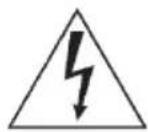
The lightning flash with an arrowhead symbol within an equilateral triangle is intended to alert the user to the presence of uninsulated "dangerous voltage" within the product's enclosure that may be of sufficient magnitude to constitute a risk of electric shock to persons.
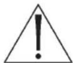
The exclamation point within an equilateral triangle is intended to alert the user to presence of important operating and maintenance (servicing) instructions in the literature accompanying the appliance.
WARNING: TO PREVENT FIRE OR SHOCK HAZARD, DO NOT EXPOSE UNITS TO RAIN OR MOISTURE.
Attention: Installation should be performed by qualified service personnel only in accordance with the National Electrical Code or applicable local codes.
24 VAC Units: Do Not Exceed 30 VAC Input. Voltage applied to the unit's power input should not exceed 30VAC. Normal input voltage is 24 VAC. User supplied wiring from 24 VAC supply to unit must be in compliance with electrical codes (Class 2 power levels). Do not ground 24 VAC supply at power supply terminals or at unit's power supply terminals.
SECURITE
ATTENTION
RISQUE DÍ OCUTION. NE PAS OUVRIR
DANGER: POUR ÉVITERTOUT RISQUE D'ÉLECTROCUTION, NE PAS OUVRIR LE BOÎTIER. IL N'Y A PAS DE PIÈCES REM-PLAÇABLES À L'INTÉRIEUR. POURTOUTE RÉVISION, S'ADRESSER À UNTECHNICIEN SPÉCIALISÉ.
(U.S.A. and Canadian Models Only)
WARNING - This equipment has been tested and found to comply with the limits for a Class A digital device, pursuant to Part 15 of the FCC Rules and ICES-003 of Industry Canada. These limits are designed to provide reasonable protection against harmful interference when the equipment is operated in a commercial environment. This equipment generates, uses, and can radiate radio frequency energy and, if not installed and used in accordance with the instruction manual, may cause harmful interference to radio communications. Operation of this equipment in a residential area is likely to cause harmful interference in which case the user will be required to correct the interference at his own expense. Intentional or unintentional changes or modifications not expressly approved by the party responsible for compliance shall not be made. Any such changes or modifications could void the user's authority to operate the equipment.
If necessary, the user should consult the dealer or an experienced radio/television technician for corrective action. The user may find the following booklet prepared by the Federal Communications Commission helpful: "How to Identify and Resolve Radio-TV Interference Problems." This booklet is available from the U.S. Government Printing Office, Washington, DC 20402, Stock No.004-000-00345-4.
Warning: This is a Class A product. In a domestic environment, this product may cause radio interference in which case the user may be required to take adequate measures.
1. UNPACKING
Unpack carefully. This is an electromechanical device and should be handled carefully. Check to ensure that the following items are included:
- Integrated camera/housing unit.
- Hardware kit: special Allen wrench.
- Desiccant Kit
• 2-position terminal block (non-UTP versions)
Model Designation
Compare the model designation printed on the unit's label to the list below before reviewing these instructions.
MLA2CH211 Color, Hi-Res, Camera, 2.8-11mm Al IR lens, 24VAC
MLA2WD211 Wide Dynamic Range Camera, 2.8-11mm Al IR lens, 24VAC
MLA2DN211 True Day/Night Camera, 2.8-11mm AI IR lens, 24VAC
-U
Part numbers ending in -U: the BNC and Power leads are replaced with a UTP board and RJ45 jack. Refer to Section 5.1.2 for more information.
2. SERVICE
If the unit needs repair service or parts, the customer should contact Aigis for authorization to return as well as shipping instructions.
3. DESCRIPTION & SPECIFICATIONS
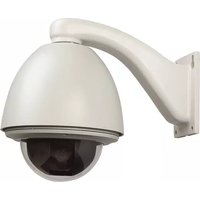
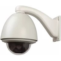
These cameras are small, high security surveillance domes containing 1/3-inch CCD cameras with integral varifocal lenses. The units come ready to use, and mount easily to a wall or ceiling. Construction/Finish: Polycarbonate Dome on cast aluminum housing.
4. COVER REMOVAL & REPLACEMENT
I. Using the special Allen wrench provided, remove the 4 tamper resistant screws located on the cover. The screws are captive and will remain with the cover. Refer to Figure 1.
2. Lift the housing off the base to make required camera adjustments. Adjust the covert liner to position the opening in front of the camera when the cover is replaced.
3. To replace the cover, align the captive screws with the threaded posts in the base, fit the cover onto the base and tighten the retaining screws securely.
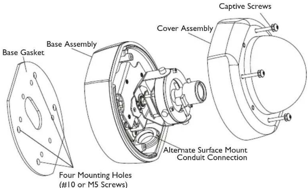
Figure I Cover Removal and Replacement
5. INSTALLATION
Attention: Installations should be performed by qualified service personnel only in accordance with the National Electrical Code or applicable local codes.
5.1 Connecting Low Voltage Power & Video Signal (Standard Models)
The wiring harness has a BNC jack to accept video coax. When mounting directly to a wall or ceiling, run power and video lines to the desired location using 3/4 inch conduit.
Caution: Before proceeding to disconnect the power at its source, be sure that the unit is of the proper voltage type for the line power.
Connect 24VAC to the unit by inserting the field supply wires into the 2-position terminal block (supplied) and tighten with a flat blade screwdriver.
Connect Video cable to the unit's BNC connector.
5.2 Connecting Low Voltage Power & Video Signals (UTP Models: part number ends in -U)
When powering the unit and transmitting video over unshielded twisted pair (UTP) wiring, ensure the UTP hub/receiver in the control room is compatible with the UTP transmitter in the camera housing. Refer to the pinout below to determine compatibility.
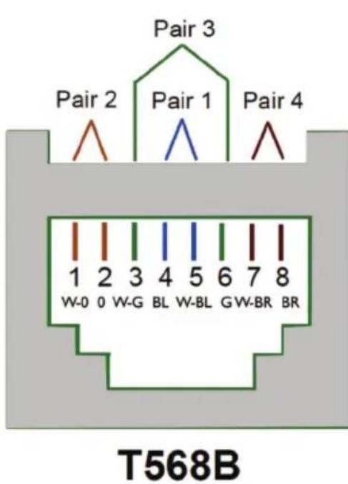
| Pin No. | Wire Color | Pair | Utilization |
| 1 White-Orange 2 | Video | Signal | |
| 2 | Orange | 2 | Video Shield |
| 3 | White-Green | 3 | Data + |
| 4 | Blue | 1 | Power - (Neutral) |
| 5 | White-Blue | 1 | Power + (Line) |
| 6 | Green | 3 | Data - |
| 7 | White-Brown | 4 | Power + (Line) |
| 8 | Brown | 4 | Power - (Neutral) |
Figure 2 Front of RJ45 Plug
Caution: Limit UTP wire runs to 1,000 feet (\~330 meters) or less.
Feed the network cable into the housing through the rear or side conduit hole. Route the cable through the housing and plug it into the RJ 45 jack shown in Figure 4. Avoid putting any tight bends into the network cable.
5.3 Mounting and/or Servicing the Unit
Refer to Figure I.
I. Using the rubber base gasket as a template, mark the mounting hole locations on the mounting surface. The unit is intended to be mounted with four #10 screws or four M5 screws (not supplied) through the four outer holes in the base casting.
2. Install the appropriate anchors or threaded fasteners.
3. Install a 3/4-inch threaded service conduit coupling into the back conduit hole, using pipe sealant on the threads. If conduit is to enter from the side, use a 2-mm Allen wrench to loosen the set screw from the conduit hole plug. Remove the plug and reinstall it in the conduit hole on the back of the unit.
IMPORTANT: If mounting outdoors, or after servicing add a generous seal/bead of RTV or silicone around the cables (on the inside of the conduit) either at the camera or at the junction box. This will help reduce moisture accumulation in the dome over long periods of time.
- If mounting this unit outdoors or after servicing, apply a generous bead of silicone sealant around the back of the base casting, surrounding all holes. Apply the rubber base gasket to the back of the base casting and apply another generous bead of sealant to the outer edge around the exposed surface of the gasket.
- Place the unit into position on the wall or ceiling. Install the mounting screws securely. If sealant is used, make sure that the sealant between the wall or ceiling and the gasket forms a complete seal. Add more sealant if needed. Make all final service connections and secure the conduit.
Important Note on Service:
I. When servicing the unit reapply silicon lubricant to the rubber gasket between the lid and cover before replacing the cover.
2. When replacing the cover make sure the gasket is aligned with the housing to ensure a proper seal.
6. CAMERA POSITION ADJUSTMENT
I. Remove dome cover.
2. Loosen Thumbnails (x3).
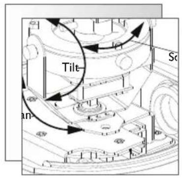
3. Make Pan adjustment by turning camera bracket in clockwise or counter clockwise motion.
4. Tilt Lens into position, then rotate face plate to square image.
5. Tighten Thumbnails.
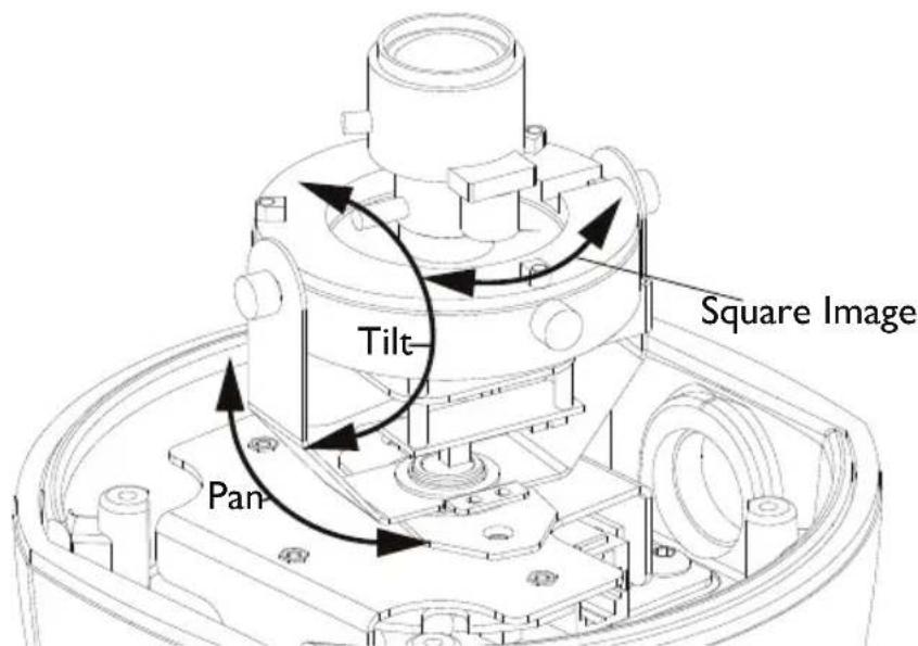
Figure 3 Camera Position Adjustment Points
7. LENS ADJUSTMENT
7.1 Adjustment Of Variable Focus Lens
I. Remove the dome cover before lens adjustment.
2. Turn the zoom knob (WIDE<->TELE) to set the field of view angle as desired. See Figure 4.
3. Next, adjust the focus by turning the focus knob (FAR<->NEAR).
4. If desired imaging field can not be obtained, repeat the steps (1) and (2).
5. Tighten knobs when adjustments are complete.
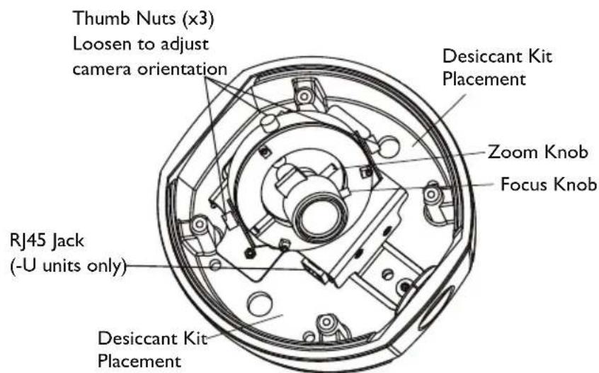
Figure 4 Adjustments
9. DESICCANT INSTALLATION
Keep Desiccant sealed in plastic bag until ready for installation. Attach Desiccant to either surface shown in Figure 4 using the adhesive pad.
DIMENSIONAL OUTLINE
![153,5 [6.04] 97,8 [3.85] 61,1 [2.41] 153,5 [6.04]](/content/2026/06/1220913/images/ca2614cdf63f1899165083a89adbb4f0f97c92db1777226b2acf92f1ddfa72fd.jpg)
![Threaded for 3/4-inch Conduit Plug Supplied 144,3 [5.68] 79 [3.11] 135,6 [5.34]](/content/2026/06/1220913/images/9bd711a5fcfe32e64c22d258cf65f990cf3bcc48976f51d49545e2ee2d064348.jpg)
- SAFETY PRECAUTIONS
- CAUTION
- SECURITE
- ATTENTION
- (U.S.A. and Canadian Models Only)
- UNPACKING
- Model Designation
- SERVICE
- DESCRIPTION & SPECIFICATIONS
- COVER REMOVAL & REPLACEMENT
- INSTALLATION
- Connecting Low Voltage Power & Video Signal (Standard Models)
- Connecting Low Voltage Power & Video Signals (UTP Models: part number ends in -U)
- Mounting and/or Servicing the Unit
- Refer to Figure I.
- Important Note on Service:
- CAMERA POSITION ADJUSTMENT
- LENS ADJUSTMENT
- Adjustment Of Variable Focus Lens
- DESICCANT INSTALLATION
- DIMENSIONAL OUTLINE
Brand : Aigis
Model : MLA2WD211
Category : Security Camera