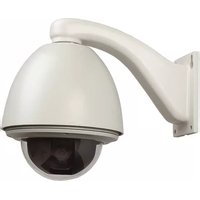
PTZA6-1W23H - Security Camera Aigis - Free user manual and instructions
Find the device manual for free PTZA6-1W23H Aigis in PDF.


| Product Type | Pan-Tilt-Zoom (PTZ) Security Camera |
| Model | PTZA6-1W23H |
| Brand | Aigis |
| Power Supply | 24VAC (via terminal block) |
| Video Output | BNC connector (75Ω coaxial cable) |
| Communication | RS485 control (4-position terminal block) |
| Alarm I/O | Alarm cable (12-position terminal block) |
| Ingress Protection | IP66 (dustproof, waterproof, moisture proof) – outdoor models |
| Lightning Protection | TVS Lightning Proof technology (surge protection up to 1500W) |
| Mounting Options | Wall, pendant, corner, pole, and recess mount (ceiling) |
| Compatible Mounting Accessories | Wall bracket, pendant bracket, corner bracket, pole bracket (all must support 4x product weight) |
| Ceiling Hole Cutout (Recess Mount) | 8.86 – 8.94 inches (225 – 227 mm) diameter |
| Coaxial Cable Requirements | 75Ω impedance, all copper conductor, 95% copper shield mesh; RG59 (max 750 ft), RG6 (max 1000 ft), RG11 (max 1500 ft) |
| Operating Environment | Outdoor (with appropriate bracket), indoor recess mount |
| Safety Factor | Minimum 4x for mounting structures |
| Sealing Required | Thread sealant tape and RTV sealant for outdoor installations |
| Dome Material | Shatter-resistant dome bubble (handle with care) |
| Cleaning | Unplug before cleaning; use damp cloth only (no liquid or aerosol cleaners) |
| Service | Refer all servicing to qualified personnel; do not attempt self-service |
| Included Accessories | 4-position and 12-position terminal blocks, hardware kit (M3 screws, etc.) |
| Warranty Information | Contact supplier for return authorization; keep original packaging |
Frequently Asked Questions - PTZA6-1W23H Aigis
User questions about PTZA6-1W23H Aigis
0 question about this device. Answer the ones you know or ask your own.
Ask a new question about this device
Download the instructions for your Security Camera in PDF format for free! Find your manual PTZA6-1W23H - Aigis and take your electronic device back in hand. On this page are published all the documents necessary for the use of your device. PTZA6-1W23H by Aigis.
USER MANUAL PTZA6-1W23H Aigis
PTZA6 Series Pan-Tilt-Zoom Domes Installation Manual
Aigis Mechtronics, Inc.
1124 Louise Road, Winston-Salem, NC 27292
Ph (336)795-7740 <ax (336)795-7744
www.aigismech.com
Table2of2Contents2
- Important Safeguards....3
1.1. Warnings....3
1.2. +environmental Specifications....3
1.3. Lightning-Proof Requirements....3
1.4. Lightning and Surge Proofing....4
1.5. Water Proofing....4
- Installation 4
2.1. Before You Start....4
2.2. Materials Required....4
- Bracket Installation....4
3.1. Overview....4
3.2. Bracket Installation....5
3.2.1. Wall Bracket Installation 5
3.2.2. Pendant Bracket Installation 5
3.2.3. Corner Bracket Installation....6
3.2.4. Pole Bracket Installation 7
3.3. Wiring and Installing the Dome Cover......8
3.4. Pan/Tilt Module Installation 9
- Recess Mount Installation....10
4.1. Ceiling Hole Preparation.... 10
4.2. PTZ Module Installation....12
4.3. Trim Ring and Dome Bubble Attachment..... 12
IMPORTANT SA<+%UARDS
-
Read Instructions - All the safety and operating instructions should be read before the unit is operated.
-
Retain Instructions - The safety and operating instructions should be retained for future reference.
-
Heed Warnings - All warnings on the unit and in the operating instructions should be adhered to.
-
Follow Instructions - All operating and use instructions should be followed.
-
Cleaning - Unplug the unit from the outlet before cleaning. Do not use liquid cleaners or aerosol cleaners. Use a damp cloth for cleaning.
-
Attachments - Do not use attachments not recommended by the product manufacturer as they may cause hazards.
-
Accessories - Do not place this unit on an unstable stand, tripod, bracket, or mount. The unit may fail, causing serious injury to a person and serious damage to the unit. Use only with a stand, tripod, bracket, or mount recommended by the manufacturer or sold with the product. Any mounting of the unit should follow the manufacturer's instructions and should use a mounting accessory recommended by the manufacturer.
An appliance and cart combination should be moved with care. Quick stops, excessive force, and uneven surfaces may cause the appliance and cart combination to overturn.
- Ventilation - Openings in the enclosure, if any, are provided for ventilation, to ensure reliable operation of the unit, and to protect it from overheating. These openings must not be blocked or covered. This unit
should not be placed in a built-in installation unless proper ventilation is provided or the manufacturer's instructions have been adhered to.
-
Power Sources - This unit should be operated only from the type of power source indicated on the marking label. If you are not sure of the type of power supply you plan to use, consult your appliance dealer or local power company. For units intended to operate from battery power or other sources, refer to the operating instructions.
-
Grounding or Polarization - This unit may be equipped with a polarized alternating-current line plug (a plug having one blade wider than the other). This plug will fit into the power outlet only one way. This is a safety feature. If you are unable to insert the plug fully into the outlet, try reversing the plug. If the plug should still fail to fit, contact your electrician to replace your obsolete outlet. Do not defeat the safety purpose of the polarized plug. Alternatively, this unit may be equipped with a 3-wire grounding-type plug, a plug having a third (grounding) pin. This plug will only fit into a grounding-type power outlet. This is a safety feature. If you are unable to insert the plug into the outlet, contact your electrician to replace your obsolete outlet. Do not defeat the safety purpose of the grounding-type plug.
-
Power Cord Protection - Power supply cords should be routed so that they are not likely to be walked on or pinched by items placed upon or against them, paying particular attention to cords and plugs, convenience receptacles, and the point where they exit from the appliance.
-
Power Lines - An outdoor system should not be located in the vicinity of overhead power lines or other electric light or power circuits or where it can fall into such
power lines or circuits. When installing an outdoor system, extreme care should be taken to keep from touching such power lines or circuits as contact with them might be fatal. U.S.A. models only - refer to the National Electrical Code Article 820 regarding installation of CATV systems.
-
Overloading - Do not overload outlets and extension cords as this can result in a fire or electric shock.
-
Object and Liquid Entry - Never push objects of any kind into this unit through openings, as they may touch dangerous voltage points or short out parts that could result in a fire or electric shock. Never spill liquid of any kind on the unit.
-
Servicing - Do not attempt to service this unit yourself as opening or removing covers may expose you to dangerous voltage or other hazards. Refer all servicing to qualified service personnel.
-
Damage Requiring Service - Unplug the unit from the outlet and refer servicing to qualified service personnel under the following conditions:
a. When the power supply cord or plug is damaged.
b. If liquid has been spilled or objects have fallen into the unit.
c. If the unit has been exposed to rain or water.
d. If the unit does not operate normally by following the operating instructions. Adjust only those controls that are covered by the operating instructions, as an improper adjustment of other controls may result in damage and will often require extensive work by a qualified technician to restore the unit to its normal operation.
e. If the unit has been dropped or the cabinet has been damaged.
f. When the unit exhibits a distinct change in performance--this indicates a need for service.
-
Replacement Parts - When replacement parts are required, be sure the service technician has used replacement parts specified by the manufacturer or have the same characteristics as the original part. Unauthorized substitutions may result in fire, electric shock, or other hazards.
-
Safety Check - Upon completion of any service or repairs to this unit, ask the service technician to perform safety checks to determine that the unit is in proper operating condition.
-
Coax Grounding - If an outside cable system is connected to the unit, be sure the cable system is grounded. U.S.A. models only--Section 810 of the National Electrical Code, ANSI/NFPA No.70-1981, provides information with respect to proper grounding of the mount and supporting structure, grounding of the coax to a discharge unit, size of grounding conductors, location of discharge unit, connection to grounding electrodes, and requirements for the grounding electrode.
-
Lightning - For added protection of this unit during a lightning storm, or when it is left unattended and unused for long periods of time, unplug it from the wall outlet and disconnect the cable system. This will prevent damage to the unit due to lightning and power line surges.

1.4. Lightning and Surge Proofing
This product uses TVS Lightning Proof technology which can prevent damage to the equipment caused by lightning strickes below 1500W and impulse signals such as surge; but it is also necessary to abide by the above stated precautions to ensure electrical safety.1.5. Water Proofing
Outdoor domes are IP66 rated which indicates they are dustproof, waterproof, and moisture proof. Do not install an indoor dome in an outdoor environment. Protect the unit from damaged caused by long term water wear. Utilize thread sealant tape and RTV sealant on outdoor units.2. Installation
Note: Disregard references to RTV sealant and thread sealant tape for indoor installations.2.1. Before You Start
- Read this manual in detail. - Ensure that all installation and maintenance work is performed by technical personnel with proper qualifications and experience with this type of equipment. - All electrical work must be in accordance with the latest local and national laws and regulations including fire prevention measures. - Ensure that all components were included in the shipment. If any parts are missing contact the shipper. - Handle the pan/tilt module carefully. The camera module is designed to snap into the dome with very little effort. Do not bend and components or attempt to force the unit into place. Do not handle the dome bubble with your hands. - Make sure the installation site is sufficient in terms of structural integrity and/or available space before commencing the installation. Maintain a safety coefficient of at least 4 when installing this product. - The unit is shipped in the safest possible packaging. Keep it for possible future use. If the unit needs to be returned, replace it properly in its packaging and contact your supplier for return authorization and shipping instructions. - When using a wall mount, pendant mount, or corner mount, ensure that the mounting accessory can support at least 4 times the weight of the unit. When using a pole mount, ensure that the installation is in accordance with the lightning-proof requirements stated above. When mounting an indoor unit into the ceiling, utilize support wires if necessary and ensure that the ceiling can support the weight of the unit.2.2. Materials Required
Minimum Video Coaxial Cable Requirements: - 75Ω impedance - All copper conductor wire (core) • 95% copper shield mesh| International Gauge Max Transmission Distance |
| RG59/U 750ft (229m) |
| RG6/U 1,000ft (305m) |
| RG11/U 1,500ft (457m) |
3. Bracket Installation
Figure 2 – PTZ Unit and Acces3.1. Overview
These units were designed the installer in mind. Quick and simple connections are required to complete the installation. Some of the features include: - External threading of the external cover to easily connect the cover to the mount bracket. - Quick-attach and release mechanism used to connect the camera module to the external cover. - Simple, clearly marked connection board. - Mounting options include wall mount, pole mount, pendant mount and corner mount.  3.2. Bracket Installation
Select an appropriate mounting location such that a safety factor of 4 can be achieved.3.2.1. Wall Bracket Installation
Hold up the wall arm to the desired installation location and use it as a template to mark the center of the drill holes. The upper two holes are slotted for easy installation. Mark the portion of the slotted holes as shown in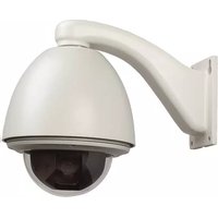

- Table2of2Contents2
- IMPORTANT SA<+%UARDS
- Important Safeguards
- Warnings
- Environmental Specifications
- Indoor Domes:
- Outdoor Domes:
- Lightning-Proof Requirements
- Lightning and Surge Proofing
- Water Proofing
- Installation
- Before You Start
- Materials Required
- Bracket Installation
- Overview
- Bracket Installation
- Wall Bracket Installation
Brand : Aigis
Model : PTZA6-1W23H
Category : Security Camera