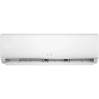
RSSC18AW-O - Refrigerator BEKO - Free user manual and instructions
Find the device manual for free RSSC18AW-O BEKO in PDF.


| Product Type | Split-type air conditioner |
| Brand | Beko |
| Model | RSSC18AW-O (Outdoor Unit) |
| Climate Class | T1 |
| Cooling Capacity | 5275 W (18000 Btu/h) |
| CSPF (Cooling Seasonal Performance Factor) | 3.69 W/W |
| Energy Grade Level | 4 |
| Air Flow Volume | 900 m³/h |
| Power Supply | 220-240 V ~ 50 Hz, 1 Ph |
| Power Input (Cooling) | 1515 W |
| Current (Cooling) | 7.2 A |
| Refrigerant Type / Charge | R32 / 1100 g |
| Noise Level (Indoor Unit) | 47 dB(A) |
| Noise Level (Outdoor Unit) | 60 dB(A) |
| Indoor Unit Dimensions (W x D x H) | 972 x 225 x 310 mm |
| Indoor Unit Net Weight | 11 kg |
| Outdoor Unit Dimensions (W x D x H) | 1038 x 378 x 294 mm |
| Outdoor Unit Net Weight | 45 kg |
| Liquid Pipe Diameter | Φ6 mm (1/4") |
| Vapor Pipe Diameter | Φ12 mm (1/2") |
| Maximum Pipe Length | 25 m |
| Maximum Height Difference | 10 m |
| Operating Modes | Auto, Cool, Heat, Dry, Fan, Sleep, Turbo, Eco |
| Remote Control | Yes (with LCD display) |
| Self-Restart Function | Yes |
| Filter Type | Washable anti-dust filter (optional electrostatic/deodorant) |
| Installation Requirements | Professional installation required; room area ≥ 15 m² for 18k model with R32 |
Frequently Asked Questions - RSSC18AW-O BEKO
User questions about RSSC18AW-O BEKO
0 question about this device. Answer the ones you know or ask your own.
Ask a new question about this device
Download the instructions for your Refrigerator in PDF format for free! Find your manual RSSC18AW-O - BEKO and take your electronic device back in hand. On this page are published all the documents necessary for the use of your device. RSSC18AW-O by BEKO.
USER MANUAL RSSC18AW-O BEKO
Split-type room air conditioner
User Manual

natural_image
Front view of a white air conditioner unit with 'beko' branding and digital display (no text or symbols on body)RSSC09AW-I / RSSC09AW-O
RSSC12AW-I / RSSC12AW-O
RSSC18AW-I / RSSC18AW-O
EN
CONTENTS
INTRODUCTION TO REFRIGERANTS R32 ....1
SAFETY PRECAUTIONS 2
NAMES OF PARTS 5
INDOOR UNIT DISPLAY....6
EMERGENCY FUNCTION & AUTO-RESTART FUNCTION ....7
REMOTE CONTROLLER 8
OPERATING INSTRUCTIONS 11
INSTALLATION MANUAL....18
MAINTENANCE 32
TROUBLESHOOTING 34
SPECIFICATIONS 35
INTRODUCTION TO REFRIGERANTS R32
■ Introduction to Refrigerants R32
The refrigerants used for air conditioners are environmentally friendly hydrocarbons R32. The two kinds of refrigerants are combustible and odorless. Moreover, they can burn and explode under certain condition. However, there will be no risk of burning and explosion if you comply with the following table to install your air conditioner in a room with an appropriate area and use it correctly.
Compared with ordinary refrigerants, Refrigerants R32 are environmentally friendly and do not destroy the ozone sphere and that their values of greenhouse effect are also very low.
■ Room area requests for air conditioner with Refrigerants R32
| Refrigerants | Capacity (Btu) | Room Area |
| R32 | 9K | Above 4 m^2 |
| 12K | Above 4 m^2 | |
| 18K | Above 15 m^2 | |
| 22K/24K | Above 25 m^2 |
⚠️Warnings
●Please read the manual before installation, using, maintenance.
●Do not use means to accelerate the defrosting process or to clean, other than those recommended by the manufacturer.
●Do not pierce or burn the appliance.
●The appliance shall be stored in a room without continuously operating sources (for example: open flames, an operating ignition gas appliance or an operating electric heater.)
- Please contact the nearest after-sale service center when maintenance is necessary. At the time of maintenance, the maintenance personnel must strictly comply with the Operation Manual provided by the corresponding manufacturer and any non-professional is prohibited to maintain the air conditioner.
- It is necessary to comply with the provisions of gas-related national laws and regulations.
- It is necessary to clear away the refrigerant in the system when maintaining or scrapping an air conditioner.

Warning: Combustible & Dangerous

Read the user manual

Read the installation manual

Read the service manual
SAFETY RULES AND RECOMMENDATIONS FOR THE INSTALLER
Read this guide before installing and using the appliance.
During the installation of the indoor and outdoor units the access to the working area should be forbidden to children.
Unforeseeable accidents could happen.
⚠️ Make sure that the base of the outdoor unit is firmly fixed.
⚠️ Check that air cannot enter the refrigerant system and check for refrigerant leaks when moving the air conditioner.
⚠️ Carry out a test cycle after installing the air conditioner and record the operating data.
The ratings of the fuse installed in the built in-control unit are T 5A / 250V.
The user must protect the indoor unit with a fuse of suitable capacity for the maximum input current or with another overload protection device.
⚠ Ensure that the mains voltage corresponds to that stamped on the rating plate. Keep the switch or power plug clean. Insert the power plug correctly and firmly into the socket, thereby avoiding the risk of electric shock or fire due to insufficient contact.
⚠️ Check that the socket is suitable for the plug, otherwise have the socket changed.
The appliance must be fitted with means for disconnection from the supply mains having a contact separation in all poles that provide full disconnection under overvoltage category III conditions, and these means must be incorporated in the fixed wiring in accordance with the wiring rules.
The air conditioner must be installed by professional or qualified persons.
Do not install the appliance at a distance of less than 50 cm from inflammable substances (alcohol, etc.) Or from pressurised containers (e.g. spray cans).
⚠️ If the appliance is used in areas without the possibility of ventilation, precautions must be taken to prevent any leaks of refrigerant gas from remaining in the environment and creating a danger of fire
The packaging materials are recyclable and should be disposed of in the separate waste bins. Take the air conditioner at the end of its useful life to a special waste collection centre for disposal.
Only use the air conditioner as instructed in this booklet. These instructions are not intended to cover every possible condition and situation. As with any electrical household appliance, common sense and caution are therefore always recommended for installation, operation and maintenance.
The appliance must be installed in accordance with applicable national regulations.
⚠️ Before accessing the terminals, all the power circuits must be disconnected from the power supply.
The appliance shall be installed in accordance with national wiring regulations.
This appliance can be used by children aged from 8 years and above and persons with reduced physical, sensory or mental capabilities or lack of experience and knowledge if they have been given supervision or instruction concerning use of the appliance in a safe way and understand the hazards involved. Children shall not play with the appliance. Cleaning and user maintenance shall not be made by children without supervision.
SAFETY RULES AND RECOMMENDATIONS FOR THE USER
Do not try to install the conditioner alone; always contact specialized technical personnel.
⚠️ Cleaning and maintenance must be carried out by specialised technical personnel. In any case disconnect the appliance from the mains electricity supply before carrying out any cleaning or maintenance.
⚠ Ensure that the mains voltage corresponds to that stamped on the rating plate. Keep the switch or power plug clean. Insert the power plug correctly and firmly into the socket, thereby avoiding the risk of electric shock or fire due to insufficient contact.
Do not pull out the plug to switch off the appliance when it is in operation, since this could create a spark and cause a fire, etc.
This appliance has been made for air conditioning domestic environments and must not be used for any other purpose, such as for drying clothes, cooling food, etc.
The packaging materials are recyclable and should be disposed of in the sparate waste bins. Take the air conditioner at the end of its useful life to a special waste collection centre for disposal.
Always use the appliance with the air filter mounted. The use of the conditioner without air filter could cause an excessive accumulation of dust or waste on the inner parts of the device with possible subsequent failures.
The user is responsible for having the appliance installed by a qualified technician, who must check that it is earthed in accordance with current legislation and insert a thermomagnetic circuit breaker.
The batteries in remote controller must be recycled or disposed of properly.
Disposal of Scrap Batteries --- Please discard the batteries as sorted municipal waste at the accessible collection point.
Never remain directly exposed to the flow of cold air for a long time. The direct and prolonged exposition to cold air could be dangerous for your health. Particular care should be taken in the rooms where there are children, old or sick people.
If the appliance gives off smoke or there is a smell of burning, immediately cut off the power supply and contact the Service Centre.
The prolonged use of the device in such conditions could cause fire or electrocution.
⚠️ Have repairs carried out only by an authorised Service Centre of the manufacturer. Incorrect repair could expose the user to the risk of electric shock, etc.
⚠️ Unhook the automatic switch if you foresee not to use the device for a long time.
The airflow direction must be properly adjusted.
The flaps must be directed downwards in the heating mode and upwards in the cooling mode.
Only use the air conditioner as instructed in this booklet. These instructions are not int ended to cover every possible condition and situation. As with any electrical household appliance, common sense and caution are therefore always recommended for installation, operation and maintenance.
⚠ Ensure that the appliance is disconnected from the power supply when it will remain inoperative for a long period and before carrying out any cleaning or maintenance.
Selecting the most suitable temperature can prevent damage to the appliance.
SAFETY RULES AND PROHIBITIONS
Do not bend, tug or compress the power cord since this could damage it. Electrical shocks or fire are probably due to a damaged power cord. Specialised technical personnel only must replace a damaged power cord.
Do not use extensions or gang modules.
Do not touch the appliance when barefoot or parts of the body are wet or damp.
Do not obstruct the air inlet or outlet of the indoor or the outdoor unit.
The obstruction of these openings causes a reduction in the operative efficiency of the conditioner with possible consequent failures or damages.
In no way alter the characteristics of the appliance.
Do not install the appliance in environments where the air could contain gas, oil or sulphur or near sources of heat.
This appliance is not intended for use by persons (including children) with reduced physical, sensory or mental capabilities, or lack of experience and knowledge, unless they have been given supervision or instruction concerning use of the appliance by a person responsible for their safety.
Do not climb onto or place any heavy or hot objects on top of the appliance.
Do not leave windows or doors open for long when the air conditioner is operating.
Do not direct the airflow onto plants or animals.
A long direct exposition to the flow of cold air of the conditioner could have negative effects on plants and animals.
Do not put the conditioner in contact with water.
The electrical insulation could be damaged and thus causing electrocution.
Do not climb onto or place any objects on the outdoor unit
Never insert a stick or similar object into the appliance. It could cause injury.
Children should be supervised to ensure that they do not play with the appliance. If the supply cord is damaged, it must be replaced by the manufacturer, its service agent or similarly qualified persons in order to avoid a hazard.
NAMES OF PARTS
| INDOOR UNIT | |
| No. | Description |
| 1 | Front panel |
| 2 | Air filter |
| 3 | Optional filter (if installed) |
| 4 | LED Display |
| 5 | Signal receiver |
| 6 | Terminal block cover |
| 7 | Ionizer generator(if installed) |
| 8 | Deflectors |
| 9 | Emergency button |
| 10 | Indoor unit rating label (Stick position optional) |
| 11 | Airflow direction louver |
| 12 | Remote controller |

| OUTDOOR UNIT | |
| No. | Description |
| 13 | Air outlet grille |
| 14 | Outdoor unit rating label |
| 15 | Terminal block cover |
| 16 | gas valve |
| 17 | liquid valve |

Note: the above figures are only intended to be a simple diagram of the appliance and may not correspond to the appearance of the units that have been purchased.

| No. | Led | Function | |
| 1 | TIMER | ➀ | Lights up during Timer operation. |
| 2 | SLEEP | ➂ | SLEEP mode |
| 3 | Temperature display (if present)/Error code | 88 | (1) Lights up during Timer operation when the air conditioner is operational(2)Displays the malfunction code when fault occurs. |

The shape and position of switches and indicators may be different according to the model, but their function is the same.
EMERGENCY FUNCTION & AUTO-RESTART FUNCTION
AUTO-RESTART FUNCTION
The appliance is preset auto - restart function by manufacturer. In case of a sudden power failure, the module memorizes the setting conditions before the power failure. when the power restores, the unit restarts automatically with all the previous settings preserved by the memory function.
To deactivate the AUTO-RESTART function, proceed as follows:
- Switch the air conditioner off and plug it off.
- Press the emergency button meanwhile plug it in.
- Keep pressing the emergency button for more than 10 seconds until you hear four short beeps from the unit. The AUTO-RESTART function is deactivate.
- To activate the AUTO - RESTART function, follow the same procedure until you hear three short beeps from the unit.
EMERGENCY FUNCTION
If the remote controller fails to work or maintenance necessary, proceed as following:
Open and lift the front panel up to an angle to reach the emergency button.
For heating model, press the emergency button at first time, the unit will operate in COOL mode. Press at second time within 3 seconds, the unit will operate in HEAT mode. Press at third time after 5 seconds, the unit will turn off.
For cooling only model, press the emergency button at first time, the unit will operate in COOL mode. Press again, the unit will turn off.

The emergency button is located on E-box cover of the unit under the front panel.
⚠ The shape and position of the emergency button may be different according to the model, but their function is the same.
Remark: the external static pressure of heat pumps is 0 Pa for all models.
REMOTE CONTROL
| No. | Button | Function |
| 1 | (TEMP UP) | Press it to increase temperature / time setting. |
| 2 | (TEMP DN) | Press it to decrease temperature/ time setting. |
| 3 | [vccz] ON/OFF | Press it to start or stop operation. |
| 4 | FAN | To select the fan speed of auto/low/mid/high |
| 5 | TIMER | Press it to set auto-off timer. |
| 6 | SLEEP | To activate the function “SLEEP” |
| 7 | ECO | In cooling mode,press this button ,the temperature will increase 2°C on the base of setting temperatureIn heating mode, press this button, the temperature will decrease 2°C on the base of setting temperature |
| 8 | MODE | To select the mode of operation |
| 9 | TURBO | Press this button to activate / deactivate the Super function which enables the unit to reach the preset temperature in the shortest time.In COOL mode, the unit will give the maximum cooling temperature with 16°C,high fan speed.In HEAT mode, the unit will give the maximum heating temperature with 31°C,high fan speed. |
| 10 | SWING | To activate or deactivate of the movement of the deflectors. |
| 11 | DISPLAY | To switch on/off the LED display |
| 12 | Mute | To activate the function of Mute. |
| 13 | Zone follow | To switch active /deactive "Zone Follow" function.The air conditioner will regulate the room temperature based on the temperature(0°C~50°C)around the remote controller.This function will terminate 2 hours later once it's active. (If applicable) |
| 14 | (MODE+TIMER) | To activate the function of Child Lock when press MODE and TIMER buttons together. (If applicable) |
The out looking and some function of remote controller maybe difference.
The shape and position of buttons and indicators may be difference according to the model, but their function is the same.
The unit confirms the correct reception of each press button with a beep.

The out looking and some function of remote controller maybe difference.
The shape and position of buttons and indicators may be difference according to the model, but their function is the same.
Remote controller DISPLAY Meaning of symbols on the liquid crystal display
| No. | Symbols | Meaning |
| 1 | AUTO mode indicator | |
| 2 | COOLING indicator | |
| 3 | DEHUMIDIFYING indicator | |
| 4 | FAN ONLY OPERATION indicator | |
| 5 | HEATING indicator | |
| 6 | SIGNAL RECEPTION indicator | |
| 7 | TIMER OFF indicator | |
| 8 | TIMER ON indicator | |
| 9 | AUTO FAN indicator | |
| 10 | LOW FAN SPEED indicator | |
| 11 | MIDDLE FAN SPEED indicator | |
| 12 | HIGH FAN SPEED indicator | |
| 13 | SLEEP indicator | |
| 14 | FLAP SWING indicator | |
| 15 | TUBRO indicator | |
| 16 | ECO indicator | |
| 17 | CLOCK indicator | |
| 18 | Zone Follow indicator |

REMOTE CONTROL
Replacement of Batteries
Remove the battery cover plate from the rear of the remote controller, by sliding it in the direction of the arrow.
Install the batteries according the direction (+and -) shown on the Remote Controller.
Reinstall the battery cover by sliding it into place.
Use 2 LRO 3 AAA (1.5V) batteries. Do not use rechargeable batteries. Replace the old batteries with new ones of the same type when the display is no longer legible.
Do not dispose batteries as unsorted municipal waste. Collection of such waste separately for special treatment is necessary.
Refer to picture 1:
i. When you open the battery cover, you can see a DIP switch on the cover back.
| DIP switch on position | Function |
| °C | The remote controller is adjusted in degree celsius |
| °F | The remote controller is adjusted in degree fahrenheit. |
| Cool | The remote controller is adjusted in only cooling mode |
| Heat | The remote controller is adjusted in cooling and heating mode |
II. NOTE: After adjusting the function, you need to take out the batteries and repeat the procedure described above.
Refer to picture 2:
When you insert the batteries for the first time in the remote controller or if you change them, you need to program the remote controller of only cooling or cooling and heating.
When you insert the batteries, the symbols (COOL■) and (HEAT■) start fashing. If you push whatever button when the symbol (COOL■) is displayed, the remote controller is adjusted in only cooling mode. If you push whatever button when the symbol (HEAT■) is displayed, the remote controller is adjusted in Cooling and heating mode.
NOTE:if you adjust the remote controller in cooling mode, it will not be possible to activate the heating function in units with heating pump. you need to take out the batteries and repeat the procedure described above.
-
Direct the remote controller toward the Air conditioner.
-
Check that there are no objects between the remote control and the Signal receptor in the indoor unit.
-
Never leave the remote controller exposed to the rays of the sun
-
Keep the remote controller at a distance of at least 1m from the television or other electrical appliances.

natural_image
Diagram showing two connected electronic components with arrows indicating connection (no text or symbols)


Recommendations for locating and using the remote controller holder (if present)
The remote controller be kept in a wall-mounted holder

OPERATING INSTRUCTIONS
The air sucked by the fan enters from the grill and passes through the filter, then it is cooled/dehumidified or heated through the heat exchanger.
The direction of the air outlet is motorized up and down by flaps, and manually moved right and left by the vertical deflectors, for some models, the vertical deflectors could be controlled by motor as well.

"SWING" CONTROL OF THE AIR FLOW
SWING
- The air outlet flow is uniformly distributed in the room.
- It is possible to position the direction of the air in the optimal.
The key SWING activates the FLAP, "the air flow is directed alternatively from up to down. In order to guarantee an even diffusion of the air in the room.
The key SWING activates the motorized deflectors, "the air flow is directed alternatively from left to right. (Optional function, depends on the models)
- In cooling mode, orient the flaps in horizontal direction;
- In heating mode, orient the flaps downward as the warm air tends to rise.
The deflectors are positioned manually and placed under the flaps. They allow to direct the air flow rightward or leftward.

This adjustment must be done while the appliance is switched off.


Never position Flaps manually, the delicate mechanism might be seriously damaged!

Never poke fingers, sticks or other objects in the air inlet or outlet vents. Such accidental contact with live parts might cause unforeseeable damage or hurt.

OPERATING INSTRUCTIONS
COOLING MODE

The cooling function allows the air conditioner to cool the room and at the same time reduces Air humidity.
To activate the cooling function (COOL), press the MODE button until the symbol ✪ (COOL ■) appears on the display.
The cooling function is activated by setting the button or at a temperature lower than that of the room.
To optimize the function of the Air conditioner, adjust the temperature (1), the speed (2) and the direction of the air flow (3) by pressing the button indicated.

HEATING MODE

The heating function allows the air conditioner to heat the room.
To activate the heating function (HEAT), press the MODE button until the symbol ⚙ (HEAT ■) appears on the display.
With the button ▲ or set a temperature higher than that of the room..
To optimize the function of the Air conditioner adjust the temperature (1), the speed (2) and the direction of the air flow (3) by pressing the button indicated

If the appliance is fitted with a electrical heater, which delays appliance to startup in a few seconds to ensure an immediate output of hot air (Optional, depends on the model).

In HEATING operation, the appliance can automatically activate a defrost cycle, which is essential to clean the frost on the condenser so as to recover its heat exchange function. This procedure usually lasts for 2-10 minutes during defrosting, indoor unit fan stop operation. After defrosting, it resumes to HEATING mode automatically.
* This function does not available in cooling only model.

OPERATING INSTRUCTIONS
TIMER MODE----TIMER ON
TIMER
To set the time of the air conditioner
To program the automatic switching-on time, the appliance should be power off.
Press TIMER at the fist time, set the temperature with pressing the button ▲ or ; ▼
Press TIMER at the second time, set the rest time with pressing the button ▲ or ; ▼
Press TIMER at the third time, confirm the setting, then the rest time to next automatic switching-on could be read on the display.
NOTE!
Before proceeding with the time: program the working mode with the button MODE (2) and the fan speed with the button FAN (3). Switch the conditioner off (with the key ON/OFF).
Note: To cancel the set function, press the TIMER button again.
Note: In case of power off, it is necessary to set TIMER ON again
To set the automatic switching-off of the air conditioner
The timed stop is programmed by pressing TIMER, Set the rest time by pressing the button ▲ or ▼, until the rest time displayed is to your demand then press TIMER again.
Note: To cancel the set function, press the TIMER button again.
Note: In case of power off, it is necessary to set TIMER OFF again

Note: When the time is set correctly on the remote, the timer function can be used and set in half hour increments.
TIMER ON


Indoor display
TIMER OFF


POWER SLEEP


Indoor display
OPERATING INSTRUCTIONS
FAN MODE
FAN
The conditioner works in only ventilation.
To set the FAN mode, Press MODE until (FAN ■) appears in the display.
While pressing FAN button the speed changes in the following sequence: LOW/ MEDIUM/HIGH /AUTO in FAN mode.
The remote control also stores the speed that was set in the previous mode of operation.
In AUTO mode (automatic) the air conditioner automatically chooses the fan speed and the mode of operation (COOLING or HEATING).


DRY MODE
DRY
This function reduces the humidity of the air to make the room more comfortable.
To set the DRY mode, Press MODE until (DRY ■) appears in the display. An automatic function of alternating cooling cycles and air fan is activated.


OPERATING INSTRUCTIONS
AUTO MODE
AUTO
Automatic mode.
To activate the AUTO (automatic) mode of operation, press the MODE button on the remote controller until the symbol △ (AUTO■) appears on the display.
In AUTO mode the fan speed and the temperature are set automatically according to the room temperature (tested by the temperature sensor which is incorporated in the indoor unit).
| Ambient temp | Operation mode | Auto temp. |
| < 20°C | HEATING (FOR HEAT PUMP TYPE)FAN (FOR COOL ONLY TYPE) | 23°C |
| 20°C~26°C | DRY | 18°C |
| >26°C | COOL | 23°C |
To optimize the function of the air conditioner, adjust the temperature(only 2) (1), the speed (2) and the direction of the air flow (3) by pressing the buttons indicated
AUTO


SLEEP MODE
SLEEP
To activate the SLEEP mode of operation, press the SLEEP button on the remote controller until the symbol (SLEEP) appears on the display.
The function SLEEP automatically adjusts the temperature to make the room more comfortable during the night. In cooling or dry mode, the set temperature will automatically raise by 1 every 60 minutes, to achieve a total rise of 2 during the first 2 hours of operation.
In heating mode the set temperature is gradually decreased by 2 during the first 2 hours of operation.
After 10 hours running in sleep mode the air conditioner is swicthed off automatically.
SLEEP


26

●
TIMER
RUN
Indoor display
OPERATING INSTRUCTIONS
TURBO MODE

Turbo mode.
To activate the TURBO mode of operation, press the TURBO button on the remote control until the symbol 🔒 appears in the display.
In cooling mode, press this button, the unit will give the maximum cooling temperature with 16^ C. In heating mode, press this button, the unit will give the maximum heating temperature with 31^ C.

ECO MODE

Eco mode.
To activate the ECO (economic) mode of operation. Press the ECO button on the remote controller until the symbol 📋 appears in the display. In cooling mode, the temperature will increase 2°on the base of setting temperature, in the heating mode, the temperature will decrease 2°on the base of setting temperature. Press again, the air conditioner switched off ECO mode automatically. The SUPER mode and ECO mode can't work together.

Zone Follow MODE

This function enable the remote control to measure the temperature at its current location and send this signal 7 times in 2 hours to the air conditioner to enable the air conditioner to optimize the temperature around you and ensure maximum comfort.
It will automatically deactivate 2 hours late after the activation or temperature exceed the range 0\~50°C

MUTE function (Optional)
MUTE
- Press MUTE button to active this function, and will appears on the remote display. Do it again to deactivate this function.
- When the MUTE function runs, the remote controller will display the auto fan speed, and the indoor unit will operate at lowest fan speed to be quiet feeling.
- When press FAN/TURBO/SLEEP button, the MUTE function will be cancel. MUTE function can not be activated under dry mode.
DISPLAY function (Indoor display)
DISPLAY
Turn on/off the indoor display.
Press DISPLAY button to switch off the LED display on the panel. Press again to switch on the LED display.


OPERATING INSTRUCTIONS
Operating Temperature
The air conditioner is programmed for comfortable and suitable living conditions as below if used outside the conditions, certain safety protection features might come into effect.,
Fix air conditioner:
| MODE Temperature | Cooling operating | Heating operating | Drying operating |
| Room temperature | 17°C32 0°C27 18 ~32 | °C °C | °C °C |
| Outdoor temperature | 0°C43 °C For T1 Climate | -7°C24 0°C50 | °C °C |
| 0°C52 °C For T3 Climate |
Inverter air conditioner:
| MODE Temperature | Cooling operating | Heating operating | Drying operating |
| Room temperature | 17°C32 0°C30 10 ~32 | °C °C | °C °C |
| Outdoor temperature | 0°C53 °C | -15°C30 0°C50 | °C °C |
| -15°C53 °C For models with low temperature cooling system |
The unit does not operate immediately if it is turned on after being turned off or after changing the mode during operation. This is a normal self-protection action, you need waiting for about 3 minutes.
The capacity and efficiency are according to the test conducted at full-load operation*. *The highest speed of indoor fan motor and the maximum open angle of the flaps and deflectors are requested.
INSTALLATION MANUAL---Important considerations
■ Important Considerations
- The air conditioner you buy must be installed by professional personnel and the “Installation manual” is used only for the professional installation personnel! The installation specifications should be subject to our after-sale service regulations.
- When filling the combustible refrigerant, any of your rude operations may cause serious injury or injuries to human body or bodies and object or objects.
● A leak test must be done after the installation is completed. - It is a must to do the safety inspection before maintaining or repairing an air conditioner using combustible refrigerant in order to ensure that the fire risk is reduced to minimum.
- It is necessary to operate the machine under a controlled procedure in order to ensure that any risk arising from the combustible gas or vapor during the operation is reduced to minimum.
- Requirements for the total weight of filled refrigerant and the area of a room to be equipped with an air conditioner (are shown as in the following Tables GG.1 and GG.2)

The maximum charge and the required minimum floor area
$$ m _ {1} = \left(4 m ^ {3}\right) \times L F L, m _ {2} = \left(2 6 m ^ {3}\right)) \times L F L, m _ {3} = \left(1 3 0 m ^ {3}\right) \times L F L $$
Where
LFL^3
3
is the lower ^3 flami
For the appliances with a charge amount m_1 < M = m_2 :
The maximum charge in a room shall be in accordance with the following: m_=2.5×(LFL)^(5/4)× h_0×(A)^1/2
The required minimum floor area Amin to install an appliance with refrigerant charge M (kg) shall be in accordance with following: A_ = (M / (2.5 × (LFL)^(5/4) × h_))^2
Where:
m_max is the allowable maximum charge in a room, in kg;
M is the refrigerant charge amount in appliance, in kg;
Amin is the required minimum room area, in m2;
A is the room area, in m ^2 ;
LFL is the lower flammable limit, in kg/m³;
h_0 is the installation height of the appliance, in meters for calculating m_max or A_min , 1.8 m for wall mounted;
Table GG.1 - Maximum charge (kg)
| Category | LFL (kg/m3) | h0(m) | Floor area (m2) | ||||||
| 4 | 7 | 10 | 15 | 20 | 30 | 50 | |||
| R290 | 0.038 | 0.6 | 0.05 | 0.07 | 0.08 | 0.1 | 0.11 | 0.14 | 0.18 |
| 1 | 0.08 | 0.11 | 0.13 | 0.16 | 0.19 | 0.2 | 0.3 | ||
| 1.8 | 0.15 | 0.2 | 0.24 | 0.29 | 0.34 | 0.41 | 0.53 | ||
| 2.2 | 0.18 | 0.24 | 0.29 | 0.36 | 0.41 | 0.51 | 0.65 | ||
| R32 | 0.306 | 0.6 | 0.68 | 0.9 | 1.08 | 0.32 | 1.53 | 1.87 | 2.41 |
| 1 | 1.14 | 1.51 | 1.8 | 2.2 | 2.54 | 3.12 | 4.02 | ||
| 1.8 | 2.05 | 2.71 | 3.24 | 3.97 | 4.58 | 5.61 | 7.254 | ||
| 2.2 | 2.5 | 3.31 | 3.96 | 4.85 | 5.6 | 6.86 | 8.85 | ||
Table GG.2 - Minimum room area ( m^2 )
| Category | LFL(kg/m3) | h_0 (m) | Charge amount (M) (kg)Minimum room area (m2) | ||||||
| R290 | 0.038 | 0.152kg | 0.228kg | 0.304kg | 0.456kg | 0.608kg | 0.76kg | 0.988kg | |
| 0.6 | 82 | 146 | 328 | 584 | 912 | 1514 | |||
| 1 | 30 | 53 | 118 | 210 | 328 | 555 | |||
| 1.8 | 9 | 16 | 36 | 65 | 101 | 171 | |||
| 2.2 | 6 | 11 | 24 | 43 | 68 | 115 | |||
| R32 | 0.306 | 1.224kg | 1.836kg | 2.448kg | 3.672kg | 4.896kg | 6.12kg | 7.956kg | |
| 0.6 | 29 | 51 | 116 | 206 | 321 | 543 | |||
| 1 | 10 | 19 | 42 | 74 | 116 | 196 | |||
| 1.8 | 3 | 6 | 13 | 23 | 36 | 60 | |||
| 2.2 | 2 | 4 | 9 | 15 | 24 | 40 | |||
■ Installation Safety Principles
1. Site Safety


Open Flames Prohibited Ventilation Necessary
2. Operation Safety

Open Flames Prohibited


Mind Static Electricity Must wear protective clothing and anti-static gloves Don't use mobile phone
3. Installation Safety
● Refrigerant Leak Detector
- Appropriate Installation Location

The left picture is the schematic diagram of a refrigerant leak detector.
Please note that:
- The installation site should be in a well-ventilated condition.
- The sites for installing and maintaining an air conditioner using Refrigerant R290 should be free from open fire or welding, smoking, drying oven or any other heat source higher than 370? which easily produces open fire; the sites for installing and maintaining an air conditioner using Refrigerant R32 should be free from open fire or welding, smoking, drying oven or any other heat source higher than 548? which easily produces open fire.
- When installing an air conditioner, it is necessary to take appropriate anti-static measures such as wear anti-static clothing and/or gloves.
- It is necessary to choose the site convenient for installation or maintenance wherein the air inlets and outlets of the indoor and outdoor units should be not surrounded by obstacles or close to any heat source or combustible and/or explosive environment.
- If the indoor unit suffers refrigerant leak during the installation, it is necessary to immediately turn off the valve of the outdoor unit and all the personnel should go out till the refrigerant leaks completely for 15 minutes. If the product is damaged, it is a must to carry such damaged product back to the maintenance station and it is prohibited to weld the refrigerant pipe or conduct other operations on the user's site.
- It is necessary to choose the place where the inlet and outlet air of the indoor unit is even.
- It is necessary to avoid the places where there are other electrical products, power switch plugs and sockets, kitchen cabinet, bed, sofa and other valuables right under the lines on two sides of the indoor unit.
Special Tools
| Tool Name Requirement(s) for Use | |
| Mini Vacuum Pump | It should be an explosion-proof vacuum pump; can ensure certain precision and its vacuum degree should be lower than 10Pa. |
| Filling Device | It should be a special explosion-proof filling device; have certain precision and its filling deviation should be less than 5g. |
| Leak Detector | It should be calibrated regularly; and its annual leak rate should not exceed 10g. |
| Concentration Detector | A) The maintenance site should be equipped with a fixed-type combustible refrigerant concentration detector and connected to a safeguard alarm system; its error must be not more than 5%.B) The installation site should be equipped with a portable combustible refrigerant concentration detector which can realize two-level audible and visual alarm; its error must be not more than 10%.C) The concentration detectors should be calibrated regularly.D) It is necessary to check and confirm the functions before using the concentration detectors. |
| Pressure Gauge | A) The pressure gauges should be calibrated regularly.B) The pressure gauge used for Refrigerant 22 can be used for Refrigerants R290 and R161; the pressure gauge used for R410A can be used for Refrigerant 32. |
| Fire Extinguisher | It is necessary to carry fire extinguisher(s) when installing and maintaining an air conditioner. On the maintenance site, there should be two or more kinds of dry powder, carbon dioxide and foam fire extinguishers and that such fire extinguishers should be placed at stipulated positions, with eye-catching labels and in handy places. |
INSTALLATION MANUAL---Selecting the Installation Place
INDOOR UNIT
• Install the indoor unit on a strong wall that is not subject to vibrations.
- The in let and outlet ports should not be obstructed: the air should be able to blow all over the room.
- Do not install the unit near a source of heat, steam, or flammable gas.
• Install the unit near an electric socket or private circuit.
- Do not install the unit where it will be exposed to direct sunlight.
- Select a site where the condensed water can be easily drained out, and where it is easily connected to outdoor unit.
- Check the machine operation regularly and reserve the necessary spaces as shown in the picture.
- Select a place where the filter can be easily taken out.
OUTDOOR UNIT
- Do not install the outdoor unit near sources of heat, steam or flammable gas.
- Do not install the unit in too windy or dusty places.
- Do not install the unit where people often pass. Select a place where the air discharge and operating sound will not disturb the neighbours.
- Avoid installing the unit where it will be exposed to direct sunlight (other wise use a protection, if necessary, that should not interfere with the air flow).
- Reserve the spaces as shown in the picture for the air to circulate freely.
• Install the outdoor unit in a safe and solid place. - If the outdoor unit is subject to vibration, place rubber gaskets onto the feet of the unit..
Installation Diagram


minimum space to be reserved (mm) showing in the picture


The purchaser must ensure that the person and/or company who is to install, maintain or repair this air conditioner has qualifications and experience in refrigerant products.
INSTALLATION MANUAL---Installation of the Indoor unit
Before starting installation, decide on the position of the indoor and outdoor units, taking into account the minimum space reserved around the units

Do not install your air conditioner in a wet room such as a bathroom or laundry etc

The installation site should be 250cm or more above the floor.
To install, proceed as follows:
Installation of the mounting plate
1 Always mount the rear panel horizontally and vertically
2. Drill 32 mm deep holes in the wall to fix the plate;
3. Insert the plastic anchors into the hole;
4 .Fix the rear panel on the wall with provided tapping screws
5. Be sure that the rear panel has been fixed firmly enough to withstand the weight
Note : The shape of the mounting plate may be different from the one above, but installation method is similar.
Drilling a hole in the wall for the piping
- Make the piping hole (\$5) in the wall at a slight downward slant to the outdoor side.
- Insert the piping-hole sleeve into the hole to prevent the connection piping and wiring from being damaged when passing through the hole.

The hole must slope downwards towards the exterior
Note : Keep the drain pipe down towards the direction of the wall hole, otherwise leakage may occur.
Electrical connections---Indoor unit
- Open the front panel.
- Take off the cover as indicated in the picture (by removing a screw or breaking the hooks).
- For the electrical connections, see the circuit diagram on the right part of the unit under the front panel.
- Connect the cable wires to the screw terminals by following the numbering, Use wire size suitable to the electric power input (see name plate on the unit) and according to all current national safety code requirements.

The cable connecting the outdoor and indoor units must be suitable for outdoor use.

The plug must be accessible also after the appliance has been installed so that it can be pulled out if necessary.

An efficient earth connection must be ensured.

If the power cable is damaged, it must be replaced by an authorised Service Centre.
Note: Optional the wires can be connected to the main PCB of indoor unit by manufacturer according to the model without terminal block.


INSTALLATION MANUAL---Installation of the Indoor unit
Refrigerant piping connection
The piping can be run in the 3 directions indicated by numbers in the picture. When the piping is run in direction 1 or 3, cut a notch along the groove on the side of the indoor unit with a cutter.
Run the piping in the direction of the wall hole and bind the copper pipes, the drain pipe and the power cables together with the tape with the drain pipe at the bottom, so that water can flow freely.
- Do not remove the cap from the pipe until connecting it, to avoid dampness or dirt from entering.
- If the pipe is bent or pulled too often, it will become stiff. Do not bend the pipe more than three times at one point.
- When extending the rolled pipe, straighten the pipe by unwinding it gently as shown in the picture.
Connections to the indoor unit
- Remove the indoor unit pipe cap (check that there is no debris inside).
- Insert the fare nut and create a flange at the extreme end of the connection pipe.
- Tighten the connections by using two wrenches working in opposite directions.
- For R32/R290 refrigerants, mechanical connectors should be outdoors.
Indoor unit condensed water drainage
The indoor unit condensed water drainage is fundamental for the success of the installation.
- Place the drain hose below the piping, taking care not to create siphons.
- The drain hose must slant downwards to aid drainage.
- Do not bend the drain hose or leave it protruding or twisted and do not put the end of it in water. If an extension is connected to the drain hose, ensure that it is lagged when it passes into the indoor unit.
- If the piping is installed to the right, the pipes, power cable and drain hose must be lagged and secured onto the rear of the unit with a pipe connection.
1) Insert the pipe connection into the relative slot.
2) Press to join the pipe connection to the base.


INSTALLATION MANUAL---Installation of the Indoor unit
INSTALLATION OF THE INDOOR UNIT
After having connected the pipe according to the instructions, install the connection cables. Now install the drain pipe. After connection, lag the pipe, cables and drain pipe with the insulating material.
- Arrange the pipes, cables and drain hose well.
- Lag the pipe joints with insulating material, securing it with vinyl tape.
- Run the bound pipe, Cables and drain pipe through the wall hole and mount the indoor unit onto the upper part of the mounting plate securely.
- Press and push the lower part of the indoor unit tightly against the mounting plate

Covered by vinyl tape

mounting plate

natural_image
Diagram of a brick wall joint with a tool, showing no text or symbolsINSTALLATION MANUAL---Installation of the outdoor unit
- The outdoor unit should be installed on a solid wall and fastened securely.
- The following procedure must be observed before connecting the pipes and connecting cables: decide which is the best position on the wall and leave enough space to be able to carry out maintenance easily.
- Fasten the support to the wall using screw anchors which are particularly suited to the type of wall;
- Use a larger quantity of screw anchors than normally required for the weight they have to bear to aviod vibration during operation and remain fastened in the same position for years without the screws becoming loose.
- The unit must be installed following the national regulations.
Outdoor unit condensed water drainage (only for heat pump models)
The condensed water and the ice formed in the outdoor unit during heating operation can be drained away through the drain pipe
- Fasten the drain port in the 25mm hole placed in the part of the unit as shown in the picture.
- Connect the drain port and the drain pipe. Pay attention that water is drained in a suitable place.

INSTALLATION MANUAL---Installation of the outdoor unit
ELECTRICAL CONNECTIONS
- Remove the handle on the right side plate of outdoor unit.
- Connect the power connection cord to the terminal board. Wiring should fit that of indoor unit.
- Fix the power connection cord with wire clamp.
- Confirm if the wire has been fixed properly.
- An efficient earth connection must be ensured.
- Recover the handle.
CONNECTING THE PIPES
Screw the flare nuts to the outdoor unit coupling with the same tightening procedures described for the indoor unit.
To avoid leakage, pay attention to the following points:
- Tighten the flare nuts using two wrenches. Pay attention not to damage the pipes.
- If the tightening torque is not sufficient, there will probably be some leakage. With excessive tightening torque there will also be some leakage, as the flange could be damaged.
- The surest system consists in tightening the connection by using a fix wrench and a torque wrench:in this case use the table on page 30.
BLEEDING
Air and humidity left inside the refrigerant circuit can cause compressor malfunction. After having connected the indoor and outdoor units, bleed the air and humidity from the refrigerant circuit by using a vacuum pump.
Refrigerant Pressure Inspection
Air-returning Low-pressure Range of Refrigerant R290: 0.4-0.6Mpa; Air-exhausting High-pressure Range: 1.5-2.0Mpa;
Air-returning Low-pressure Range of Refrigerant R32: 0.8-1.2Mpa; Air-exhausting High-pressure Range: 3.2-3.7Mpa;
It means that the refrigerating system or refrigerant of an air conditioner is abnormal if the air-exhausting and air-returning pressure ranges of the detected compressor exceed the normal ranges to a large extent.


INSTALLATION MANUAL---Installation of the outdoor unit
BLEEDING
The air and humidity left inside the refrigerant circulation can cause compressor malfunction. After having connected the indoor and outdoor units, bleed the air and humidity from the refrigerant circulation using a vacuum pump.
(1) Unscrew and remove the caps from the 2 - way and 3-way valves.
(2) Unscrew and remove the cap from the service port.
(3) Connect the vacuum pump hose to the service port.
(4) Operate the vacuum pump for 10 - 15 minutes until an absolute vacuum of 10mmHg has been reached.
(5) With the vacuum pump still in operation, close the low - pressure knob on the vacuum pump coupling. Stop the vacuum pump.
(6) Open the 2 - way valve by 1/4 turn and then close it after 10 seconds. Check all the joints for leaks using liquid soap or an electronic leak device.
(7) Turn the body of the 2-way and 3-way valves. Disconnect the vacuum pump hose.
(8) Replace and tighten all the caps on the valves.
3-way valve diagram


flowchart
graph TD
    A["Indoor unit"] --> B["3-way valve"]
    B --> C["Service port nut"]
    C --> D["(2) Turn"]
    D --> E["(8) Tighten"]
    E --> F["Valve cap"]
    F --> G["(7) Turn to fully open the valve"]
    G --> H["Valve cap"]
    H --> I["(1) Turn"]
    I --> J["(8) Tighten"]
    J --> K["(6) Open 1/4 turn"]
    K --> L["Valve cap"]
    L --> M["(7) Turn to fully open the valve"]
    M --> N["Valve cap"]
    N --> O["(1) Turn"]
    O --> P["(8) Tighten"]
    P --> Q["(6) Open 1/4 turn"]
    Q --> R["Valve cap"]
INSTALLATION MANUAL--- operation test
- Wind insulating covering around the joints of the indoor unit and fix it with insulating tape.
- Fix the exceeding part of the signal cable to the piping or to the outdoor unit.
- Fix the piping to the wall (after having coated it with insulating tape) using clamps or insert them into plastic slots.
- Seal the hole in the wall through which the piping is passed so that no air or water can fill.
Indoor unit test
- Do the ON/OFF and FAN operate normally?
- Does the MODE operate normally?
- Do the set point and TIMER function properly?
- Does each lamp light normally?
- Do the flap for air flow direction operate normally?
• Is the condensed water drained regularly?
Outdoor unit test
- Is there any abnormal noise or vibration during operation?
• Could the noise, the air flow or the condensed water drainage disturb the neighbours?
• Is there any coolant leakage?
Note: the electronic controller allows the compressor to start only three minutes after voltage has reached the system.

INSTALLATION MANUAL---Information for the installer
| MODEL capacity (Btu/h) | 9k/12k | 18k/24k |
| Lenght of pipe with standard charge | 5m 5m | |
| Maximum distance between indoor and outdoor unit | 25m | 25m |
| Additional refrigerant charge | 15g/m 25g/m | |
| Max. diff. in level between indoor and outdoor unit | 10m | 10m |
| Type of refrigerant(1) | R32/R290 | R32/R290 |
(1) Refer to the data rating label sticked on the outdoor unit.
(2) The total charge amount should under the maximum according to the table GG.1 in page 21.
TIGHTENING TORQUE FOR PROTECTION CAPS AND FLANGE CONNECTION
| PIPE | TIGHTENING TORQUE [N x m] | CORRESPONDING STRESS (using a 20 cm wrench) | TIGHTENING TORQUE [N x m] | |
| 1/4"(Φ6) | 15 - 20 | wrist strength | Service port nut | 7 - 9 |
| 3/8"(Φ.52) | 31 - 35 | arm strength | Protection caps | 25 - 30 |
| 1/2"(Φ2) | 35 - 45 | arm strength | ||
| 5/8"(Φ5.88) | 75 - 80 | arm strength |
INSTALLATION MANUAL---Information for the installer
WIRING DIAGRAM
For different models, the wiring diagram may be different. Please refer to the wiring diagrams pasted on the indoor unit and outdoor unit respectively.
On indoor unit, the wiring diagram is pasted under the front panel;
On outdoor unit, the wiring diagram is pasted on the backside of the outdoor handle cover.

Note: For some models the wires has been connected to the main PCB of indoor unit by manufacturer without terminal block.
INSTALLATION MANUAL---Information for the installer
CABLE WIRES SPECIFICATION
| MODEL capacity (Btu/h) | 5k | 7k | 9k | 12k | 15/18k | 22/24k | 28/30k/36k | |
| sectional area | ||||||||
| Power supply cable | N | 1.0mm^2 AWG18 | 1.0mm^2 AWG18 | 1.0mm^2 AWG18 | 1.0mm^2(1.5mm) AWG18(AWG16) | 1.5mm^2 AWG16 | 2.5mm^2 AWG14H05RN-F | 4.0mm^2 AWG12 |
| L | 1.0mm^2 AWG18 | 1.0mm^2 AWG18 | 1.0mm^2 AWG18 | 1.0mm^2(1.5mm) AWG18(AWG16) | 1.5mm^2 AWG16 | 2.5mm^2 AWG4H05RN-F | 4.0mm^2 AWG12 | |
| E | 1.0mm^2 AWG18 | 1.0mm^2 AWG18 | 1.0mm^2 AWG18 | 1.0mm^2(1.5mm) AWG18(AWG16) | 1.5mm^2 AWG16 | 2.5mm^2 AWG2H05RN-F | 4.0mm^2 AWG12 | |
| Connection supply cable | N | 1.0mm^2 | 1.0mm^2 | 1.0mm^2 | 1.0mm^2(1.5mm) | 1.5mm^2 | 0.75mm^2 | 0.75mm^2 |
| L | 1.0mm^2 | 1.0mm^2 | 1.0mm^2 | 1.0mm^2(1.5mm) | 1.5mm^2 | 0.75mm^2 | 0.75mm^2 | |
| 1 | 1.0mm^2 | 1.0mm^2 | 1.0mm^2 | 1.0mm^2(1.5mm) | 1.5mm^2 | 0.75mm^2 | 0.75mm^2 | |
| 2 | 0.75mm^2 | 0.75mm^2 | 0.75mm^2 | 0.75mm^2 | 0.75mm^2 | 0.75mm^2 | 0.75mm^2 | |
| 3 | 0.75mm^2 | 0.75mm^2 | 0.75mm^2 | 0.75mm^2 | 0.75mm^2 | 0.75mm^2 | 0.75mm^2 | |
| 0.75mm^2 | 0.75mm^2 | 0.75mm^2 | 0.75mm^2 | 0.75mm^2 | 0.75mm^2 | 0.75mm^2 | ||
| INVERTER TYPEMODEL capacity (Btu/h) | 9k | 12k | 18/22k | 24k | ||||
| sectional area | ||||||||
| Power supply cable | N | 1.0mm^2 (1.5mm)AWG18(AWG16) | 1.0mm^2 (1.5mm)AWG18(AWG16) | 1.5mm^2 AWG16 | 2.5mm^2 AWG14 | |||
| L | 1.0mm^2 (1.5mm)AWG18(AWG16) | 1.0mm^2 (1.5mm)AWG18(AWG16) | 1.5mm^2 AWG16 | 2.5mm^2 AWG14 | ||||
| E | 1.0mm^2 (1.5mm)AWG18(AWG16) | 1.0mm^2 (1.5mm)AWG18(AWG16) | 1.5mm^2 AWG16 | 2.5mm^2 AWG14 | ||||
| Connection supply cable | N | 1.0mm^2 (1.5mm) | 1.0mm^2 (1.5mm) | 1.5mm^2 | 0.75mm^2 | |||
| L | 1.0mm^2 (1.5mm) | 1.0mm^2 (1.5mm) | 1.5mm^2 | 0.75mm^2 | ||||
| 1 | 1.0mm^2 (1.5mm) | 1.0mm^2 (1.5mm) | 1.5mm^2 | 0.75mm^2 | ||||
| + | 1.0mm^2 (1.5mm) | 1.0mm^2 (1.5mm) | 1.5mm^2 | 0.75mm^2 | ||||
MAINTENANCE
Periodic maintenance is essential for keeping your air conditioner efficient.
Before carrying out any maintenance, disconnect the power supply by taking the plug out from the socket.
INDOOR UNIT
ANTIDUST FILTERS
- Open the front panel following the direction of the arrow
- Keeping the front panel raised with one hand, take out the air filter with the other hand
- Clean the filter with water; if the filter is soiled with oil, it can be washed with warm water (not exceeding 45°C).
Leave to dry in a cool and dry place. - Keeping the front panel raised with one hand, insert the air filter with the other hand
- Close
The electrostatic and the deodorant filter (if installed) cannot be washed or regenerated and must be replaced with new filters after every 6 months.
CLEANING THE HEAT EXCHANGER
- Open the front panel of the unit and life it till its greatest stroke and then unhooking it from the hinges to make the cleaning easier.
- Clean the indoor unit using a cloth with the water (not higher than 40°C and neutral soap). Never use aggressive solvents or detergents.
- If the outdoor unit is clogged, remove the leaves and the waste and remove the dust with air jet or a bit of water.

natural_image
Line drawing of a cylindrical air conditioner unit with directional arrows indicating airflow or movement (no text or symbols)
natural_image
Technical line drawing of an air conditioner unit showing internal panel structure and mounting bracket (no text or symbols)antidust filter

natural_image
Cross-sectional diagram of an air conditioner unit showing internal structure and airflow direction (no text or symbols)END OF SEASON MAINTENANCE
-
Disconnect the automatic switch or the plug.
-
Clean and replace the filters
-
On a sunny day let the conditioner work in ventilation for some hours, so that the inside of the unit can dry completely..
REPLACING THE BATTERIES
When: • There is no confirmation beep heard from the indoor unit.
• The LCD doesn't act.
How: • Take off the cover at back.
- Place the new batteries respecting the symbols + and - .
N.B: Use only new batteries. Remove the batteries from the remote controller when the conditioner is not in operation
WARNING! Do not throw batteries into common rubbish, they should be disposed of in the special containers situated in the collection points.
TROUBLESHOOTING
| MALFUNCTION | POSSIBLE CAUSES | |
| The appliance does not operate | Power failure/plug pulled out | |
| Damaged indoor/outdoor unit fan motor | ||
| Faulty compressor thermomagnetic circuit breaker | ||
| Faulty protective device or fuses. | ||
| Loose connections or plug pulled out | ||
| It sometimes stops operating to protect the appliance. | ||
| Voltage higher or lower than the voltage range | ||
| Active TIMER-ON function | ||
| Damaged electronic control board | ||
| Strange odour | Air filter dirty | |
| Noise of running water | Back flow of liquid in the refrigerant circulation | |
| A fine mist comes from the air outlet | This occurs when the air in the room becomes very cold, for example in the “COOLING”or DEHUMIDIFYING/DRY modes. | |
| A strange noise can be heard | This noise is made by the expansion or contraction of the front panel due to variations in temperature and does not indicate a problem. | |
| Insufficient airflow, either hot or cold | Inappropriate temperature setting.. | |
| Air inlet or outlet of indoor or outdoor unit has been blocked. | ||
| Air filter is blocked. | ||
| Fan speed set at minimum. | ||
| Other sources of heat in the room. | ||
| No refrigerant. | ||
| The appliance does not respond to commands | Remote control is not near enough to indoor unit. | |
| Battery in Remote controller may have been exhausted.. | ||
| Obstacles between remote control and signal receiver in indoor unit. | ||
| The display is off | Active LED function | |
| Power failure | ||
| Switch off the air conditioner immediately and cut off the power supply in the event of: | ||
| Strange noises during operation. | ||
| Faulty electronic control board | ||
| Faulty fuses or switches. | ||
| Spraying water or objects inside the appliance. | ||
| Overheated cables or plugs. | ||
| Very strong smells coming from the appliance. | ||
| ERROR SIGNALS ON THE DISPLAY | ||
| In case of error, the display on the indoor unit shown the following error codes: | ||
| RUN lamp | Description of the trouble | |
| E1 | flashes once | The fault of indoor temperature sensor |
| E2 | flashes twice | The fault of indoor pipe temperature sensor |
| E6 | flashes 6 times | Malfunction of indoor fan motor. |
| Type | Indoor unit | RSSC 09 AW-I | RSSC 12 AW-I | RSSC 18 AW-I |
| Outdoor unit | RSSC 09 AW-O | RSSC 12 AW-O | RSSC 18 AW-O | |
| Climate Mode | T1 | T1 | T1 | |
| Cooling capacity(W) | 2637 | 3517 | 5275 | |
| Cooling capacity(Btu/Hr) | 9000 | 12000 | 18000 | |
| CSPF (W/W) | 3.69 | 3.62 | 3.69 | |
| Grade Level | 3 | 3 | 4 | |
| Air Flow volume(m3/h) | 510 | 620 | 900 | |
| Power Supply form(V/Hz/Ph) | 220-240V~ / 50Hz / 1Ph220-240V~ / 230Hz // 10Hz / 1Ph | |||
| PowerInput(W) | Cooling | 750 | 1015 | 1515 |
| Current(A) | Cooling | 3.6 | 4.8 | 7.2 |
| Refrigerant /Total gas quantity(g) | R32 / 530 | R32 / 560 | R32 / 1100 | |
| Noise SoundPressure(dB) | Indoor unit | 40 | 44 | 47 |
| Outdoor unit | 52 | 52 | 60 | |
| Indoor | Size of shape(WxDxH)(mm) | 728x205x285 | 820x210x306 | 972x225x310 |
| Net weight(Kg) | 8 | 9 | 11 | |
| Outdoor | Size of shape(WxDxH)(mm) | 795x355x275 | 885x366x278 | 1038x378x294 |
| Net weight(Kg) | 27 | 28 | 45 | |
| Diameter of connecting pipe(mm) | Liquid tube | Φ6(1/4") | Φ6(1/4") | Φ6(1/4") |
| Vapor tube | Φ9.52(3/8") | Φ9.52(3/8") | Φ12(1/2") | |
Notes: 1, Specifications are standard values calculated based on rated operating conditions, They will vary in difference work condition.
2, Rated Cooling value is tested under 27/19(In.) 35/24(Out.) condition.

natural_image
White air conditioner unit with 'beko' branding and digital display (no text or symbols on body)natural_image
Pure mechanical diagram showing a cross-section of a mechanical component with no text or symbolsBỘ ĐIỀU KHIỂN TỪ XA --- Pin
Thay pin
natural_image
Diagram showing two views of a mobile phone with battery and cable connections (no text or symbols)


ĐIỀU KHIỂN DÒNG KHÍ "SWING"
SWING


- Split-type room air conditioner
- User Manual
- CONTENTS
- INTRODUCTION TO REFRIGERANTS R32
- ■ Introduction to Refrigerants R32
- ■ Room area requests for air conditioner with Refrigerants R32
- ⚠️Warnings
- SAFETY RULES AND RECOMMENDATIONS FOR THE INSTALLER
- SAFETY RULES AND RECOMMENDATIONS FOR THE USER
- SAFETY RULES AND PROHIBITIONS
- NAMES OF PARTS
- EMERGENCY FUNCTION & AUTO-RESTART FUNCTION
- AUTO-RESTART FUNCTION
- EMERGENCY FUNCTION
- REMOTE CONTROL
- Replacement of Batteries
- OPERATING INSTRUCTIONS
- "SWING" CONTROL OF THE AIR FLOW
- SWING
- COOLING MODE
- HEATING MODE
- TIMER MODE----TIMER ON
- TIMER
- NOTE!
- FAN MODE
- FAN
- DRY MODE
- DRY
- AUTO MODE
- AUTO
- SLEEP MODE
- SLEEP
- TURBO MODE
- ECO MODE
- Zone Follow MODE
- MUTE function (Optional)
- MUTE
- DISPLAY function (Indoor display)
- DISPLAY
- Operating Temperature
- INSTALLATION MANUAL---Important considerations
- ■ Important Considerations
- The maximum charge and the required minimum floor area
- For the appliances with a charge amount m_1 < M = m_2 :
- ■ Installation Safety Principles
- Site Safety
- Open Flames Prohibited Ventilation Necessary
- Operation Safety
- Open Flames Prohibited
- Mind Static Electricity Must wear protective clothing and anti-static gloves Don't use mobile phone
- Installation Safety
- The left picture is the schematic diagram of a refrigerant leak detector.
- Please note that:
- Special Tools
- INSTALLATION MANUAL---Selecting the Installation Place
- INDOOR UNIT
- OUTDOOR UNIT
- INSTALLATION MANUAL---Installation of the Indoor unit
- Installation of the mounting plate
- Drilling a hole in the wall for the piping
- Electrical connections---Indoor unit
- Refrigerant piping connection
- Connections to the indoor unit
- Indoor unit condensed water drainage
- INSTALLATION OF THE INDOOR UNIT
- INSTALLATION MANUAL---Installation of the outdoor unit
- Outdoor unit condensed water drainage (only for heat pump models)
- ELECTRICAL CONNECTIONS
- CONNECTING THE PIPES
- BLEEDING
- Refrigerant Pressure Inspection
- INSTALLATION MANUAL--- operation test
- Indoor unit test
- Outdoor unit test
- INSTALLATION MANUAL---Information for the installer
- WIRING DIAGRAM
- MAINTENANCE
- ANTIDUST FILTERS
- CLEANING THE HEAT EXCHANGER
- END OF SEASON MAINTENANCE
- REPLACING THE BATTERIES
- TROUBLESHOOTING
- BỘ ĐIỀU KHIỂN TỪ XA --- Pin
- Thay pin
- ĐIỀU KHIỂN DÒNG KHÍ "SWING"
Brand : BEKO
Model : RSSC18AW-O
Category : Refrigerator