ZX-580SR240 - Security Camera VideoComm - Free user manual and instructions
Find the device manual for free ZX-580SR240 VideoComm in PDF.

User questions about ZX-580SR240 VideoComm
0 question about this device. Answer the ones you know or ask your own.
Ask a new question about this device
Download the instructions for your Security Camera in PDF format for free! Find your manual ZX-580SR240 - VideoComm and take your electronic device back in hand. On this page are published all the documents necessary for the use of your device. ZX-580SR240 by VideoComm.
USER MANUAL ZX-580SR240 VideoComm
It's About Real Time
5.8GHz Day-Night All Weather Camera Series
Manual Rev-C
OWNER'S MANUAL
(888) 379-2666 US Toll Free
(905) 336-9665 Phone
(905) 336-9662 Fax
www.VideoTransmitters.com
TABLE OF CONTENTS
It's About Real Time....1
TABLE OF CONTENTS ......2
SAFETY NOTICES....3
INTRODUCTION ....4
Advantages....4
PARTS LIST....5
PRE INSTALLATION....5
Site Evaluation....5
Identify Line-of-Sight....5
Up & in the Clear....5
Ground Plane....6
Trees Grow!......6
Unusual Traffic 6
Things that Block Transmission....6
Channel Selection 10
INSTALLATION 12
Antenna & Power Connection ....12
Universal Mounting Bracket Overview 12
Model # ZX-580SR120 Mounting Scenarios 13
Model # ZX-580SR200 Mounting Bracket Setup....13
Model # ZX-580SR200 Mounting Bracket Setup....14
TIPS & TROUBLE SHOOTING....15
OPTIONAL PRODUCTS & ACCESSORIES ....17
SPECIFICATIONS ....18
WARRANTY INFORMATION/ TERMS & CONDITIONS......19
SAFETY NOTICES
I. THIS DEVICE COMPLIES WITH FCC RULES PART 15. OPERATION IS SUBJECT TO THE FOLLOWING TWO CONDITIONS:
(1) This device may not cause harmful interference, and
(2) This device must accept any interference, including interference that may cause undesired operation of the device
II. In order to comply with the FCC/IC adopted RF exposure requirements, this transmission system will be installed by an authorized professional installer of VideoComm Technologies. Installation of all antennas must be performed in a manner that will provide at least 23cm clearance from the front radiating aperture, to any user or member of the public.
III. This is NOT an intrinsically safe device. Do not take into area where intrinsic safety is required. Bodily harm may result if warning is ignored.
IV. DO NOT OPERATE CAMERA WITHOUT ANTENNA CONNECTED TO ANTENNA PORT. Failure to do so will result in damage to the unit and void the warranty.
V. DO NOT OPERATE THE SYSTEM WHEN the Camera & Receiver are closer than ten feet to each other. The devices may not work properly and permanent damage can occur.
VI. This device has been certified by the FCC for use with other products without any further certification (as per FCC section 2.1091.) Changes or modifications not expressly approved by VideoComm Technologies could void the user's authority to operate the equipment.


Industrie Canada
Industry Canada

FCC ID SU5-T5808
Industry Canada 3677A-T5808VCT
INTRODUCTION
Introduction
All NEW and ready to install, this dynamic all-weather wireless video camera transmits 5.8GHz, FM Live Real-Time video from 300 feet up to 4 miles, depending on optional receiver. This Rugged 580 line, high resolution camera features a varifocal zoom lens and is perfect for protecting property and assets with exceptional night-vision ranging from 120 Feet up to 240 Feet model dependant.
Advantages
- Easy to Install and Operate "Plug & Play"
• 5.8GHz FM Live Real-Time Video up to 4 Miles - Night Vision Range from 120' up to 240' (Model Dependant)
• 580 Line High-Resolution Day / Night Color Camera - Convenient Adjustable External Focus and Zoom Lens
- On Screen Display Menu for Convenient Video Setup
• Samsung W-IV Digital Signal Processor (Model Dependant)
• Universal 3-Axis Mounting Bracket Included
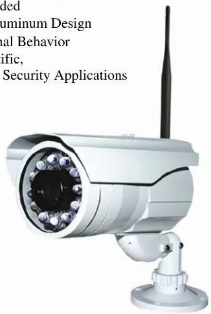
• Rugged All-Weather IP-66 Rated Cast Aluminum Design
• Deters Vandalism, Theft and other Criminal Behavior - Perfect for Commercial, Industrial, Scientific, Law Enforcement & Government Video Security Applications
VideoComm Technologies Customer Service
Bus (905) 336-9665
US Toll Free 888-379-2666
Fax (905) 336-9662
E-mail- info@VideoTransmitters.com
Web Site- www.VideoTransmitters.com
Monday - Friday 8:30am- 5:00pm
Eastern Standard Time
text_image
ded aluminum Design ual Behavior ific, Security ApplicationsModel Shown # ZX-580SR240
PARTS LIST
The 5.8GHz 580TVL All-Weather Camera Series has been carefully manufactured, tested, inspected and packaged. Please inspect the packaging carefully to ensure you have received all the necessary parts and accessories listed. Refer to the following chart to determine which parts are included with your product. If any parts are missing or damaged, contact VideoComm Technologies or your re-seller immediately.
5.8GHz Wireless Day / Night Cameras
| PARTS ZX-580SR120 | ZX-580SR200 | ZX-580SR240 | |
| All Weather Camera with Sun-Hood X | X | X | |
| 3-Axis Universal Mounting Bracket X | X | X | |
| 12VDC 1.25 Amp Power SupplyModel # PS-121A X | X | X | |
| 3dB Rubber Duck AntennaModel # RUB-5803 X | X | X | |
| Mini Philips Screw Driver X | X | X | |
| Mounting Bracket Template X | X | X | |
| Owners Manual X | X | X |
Hard Wired Day / Night Cameras
| PARTS CX-580SR120 | CX-580SR200 | CX-580SR240 | |
| All Weather Camera with Sun-Hood X | X | X | |
| 3-Axis Universal Mounting Bracket X | X | X | |
| 12VDC 1.25 Amp Power SupplyModel # PS-121A X | X | X | |
| 3dB Rubber Duck AntennaModel # RUB-5803 - | - | - | |
| Mini Philips Screw Driver X | X | X | |
| Mounting Bracket Template X | X | X | |
| Owners Manual X | X | X |
PRE-INSTALLATION
Site Evaluation
Identify Line-of-Sight
Although wireless video transmission may seem like a viable option for a particular application at first glance, there are many considerations. Is there a clear, unobstructed view between the transmitter and receiver? Are there any other devices that may cause interference? Depending on the height of the building, tower or structure, you must consider the path that the wireless video will travel between the transmitter and receiver. Line-of-Sight is defined as a clear and unobstructed view between the transmitter and receiver.
Up & in the Clear
To realize the optimum distance for your VideoComm Technologies wireless devices, “give them some air”. A good rule of thumb is to mount the devices at least 15 to 20 feet above obstructions such as the roof of a building, above parked cars in a parking lot or the top of a fence line.
See Figure 2.
Ground Plane
If the radio devices are not mounted high enough above obstructions, the signal strength will be seriously reduced; therefore your distance will be reduced. The signal will literally bounce up and away from your intended target. This is known as a negative ground plane effect. The ground plane could not only be the ground you stand on, but could also be the rooftops of cars or distant buildings. See Figure 3. If we have a choice, place the transmitter/receiver enclosures or external antenna on the edge of the roof looking AWAY from the building. Installing the device in the middle of the roof may cause decreased range. See Figure 4. This is particularly important if we have a metal roof that tends to deflect signals away from the target. Also consider any obstruction that may get in the way, like another roof or a tractor-trailer that may pass through your “Line-of-Sight”.
Trees Grow!
If we install the video link in the winter, the leaves that come out in spring may eliminate your wireless link. Are you trying to transmit through trees? Then you will need to seriously consider how much range will be lost. A field test is always the best way to find out. Speak to a VideoComm Technologies Technical support representative for a possible solution.
Unusual Traffic
Watch out for unusual traffic in your transmission path. For example, a dump truck with the back elevated while dumping a load can be much taller than expected. Tractor-trailers or other large vehicles may be a factor if trying to transmit over a highway. Metal obstructions between the antennas cannot be ignored including electrical transmission lines that may not be obvious in the distance. Each high voltage wire crossing your path can be the equivalent of transmitting past an eight-foot thick steel pipe.
© Copyright 2003 1156488 Ontario Inc.
PROBLEM:
Although technically the transmitter has line of sight with
the receiver, the video quality from the receiver will be poor.
Most of the signal is blocked by the center building and
therefore the receiver will not have enough signal strength
to output a reasonable picture.

natural_image
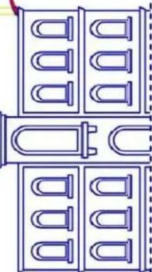
Line drawing of a multi-story building with arched windows and a central gate (no text or symbols)SOLUTIONS:
(A) - Add a high gain antenna to the receiver to increase signal strength.
or
B. Raise the transmitter and the
⑥ - kaise the transmitter and the receiver higher on a pole so that
more signal can pass through to
the receiver.

natural_image
Architectural line drawing of a multi-story building with arched windows and a central gate (no text or symbols)OBSTRUCTED - LINE OF SIGHT


text_image
or B - Raise the transmitter and the receiver higher on a pole so that more signal can pass through to the receiver. TX A RX OR RX B
other
SIDE VIEW WALL | Distance | Probability Range | | :--- | :--- | | 20 FEET | 100% OF POTENTIAL | | 10 FEET | 50-75% OF POTENTIAL | | 5 FEET | 25-50% OF POTENTIAL | | 0 FEET | GROUND PLANE |© Copyright 2003 1156488 Ontario Inc.
text_image
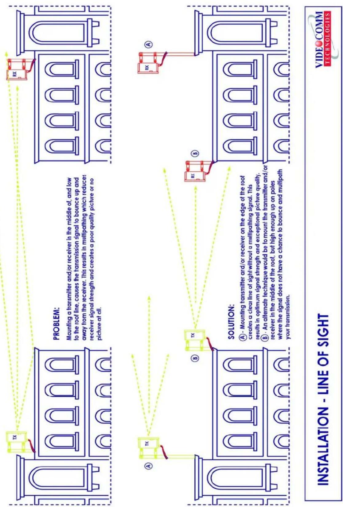
PROBLEM: Mounting a transmitter and/or receiver in the middle of, and low to the roof line, causes the transmission signal to bounce up and away from the receiver. This results in multipathing which reduces receiver signal strength and creates a poor quality picture or no picture at all. SOLUTION: A - Mounting transmitter and/or receiver on the edge of the roof creates a clear line of sight without a multipathing signal. This results in optimum signal strength and exceptional picture quality. B - An alternate technique would be to mount the transmitter and/or receiver in the middle of the roof, but high enough up on poles where the signal does not have a chance to bounce and multipath your transmission. INSTALLATION - LINE OF SIGHT VIDEO COMM TECHNOLOGIESChannel Selection
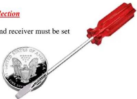
For the wireless video link to work, both the wireless camera and receiver must be set to the same channel.
Step # 1 - Remove the Cap from the rear camera housing using a Coin or Flathead Screw Driver
text_image
section and receiver must be set UNITED STATES OF AMERICA FINE SILV| Frequency | |
| Channel # 1 | 5.725 GHz |
| Channel # 2 | 5.752 GHz |
| Channel # 3 | 5.771 GHz |
| Channel # 4 | 5.790 GHz |
| Channel # 5 | 5.809 GHz |
| Channel # 6 | 5.828 GHz |
| Channel # 7 | 5.847 GHz |
| Channel # 8 | 5.875 GHz |
Step # 2 - Using the rotary switch, set your channel.
Both the Camera and Receiver must be set to the same channel
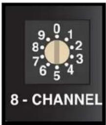
text_image
8 - CHANNELStep # 3 - Place the cap back on the rear camera housing and tighten using a Coin or Flathead screwdriver. Failure to do so may result in water damage and void the warranty. For assistance, contact Technical Support (905) 336-9665 or info@VideoTransmitters.com
Adjusting Focus & Zoom
1 To Adjust the Camera Focus & Zoom, loosen the two adjustment knobs located on the back of the camera using the included Mini Philips Screw Driver.
2 After making your adjustments, tighten both adjustment knobs using the included Mini Philips Screw Driver to ensure a water tight seal. Failure to do so may result in water damage and void the warranty. For assistance, contact Technical Support (905) 336-9665 or info@VideoTransmitters.com
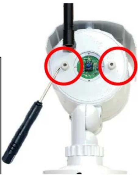
natural_image
Close-up of a white surveillance camera with green circuit board and red circular annotations highlighting the lens (no text or symbols present)INSTALLATION
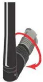
Antenna & Power Connection
Antenna Connection
Carefully thread the antenna onto the connector on the back side of the camera. Do Not use a wrench or a tool – Hand Tighten ONLY. For best transmitting pattern – Ensure the antenna is pointing “UP”
Power Connection
Only use the power supply included with this camera to ensure proper voltage and amperage.
There are THREE power indicator LEDS located next to the Frequency Channel Selection Rotary Switch.
Take note of the power indicator LEDS to ensure proper Voltage
Red LED means the Voltage is too low – Check your cable length and wiring
Green & Red means you have the Correct Voltage
Green means the Voltage is too high. Ensure the use of included power supply Model # PS-121A
Universal Mounting Bracket Overview
Connection
All camera models have the ability to mount in almost any scenario – including wall & desktop mounting. We suggest using proper counter-sink plugs when mounting the bracket to any surface and ensure proper support. For best results, use the included Mounting Bracket Template to mark the location for your counter-sink plugs & screws. Once the universal 3-Axis bracket is mounted, almost any camera angle can be achieved.
natural_image
Close-up of a black cylindrical device with a red curved arrow indicating rotation or change (no text or symbols visible)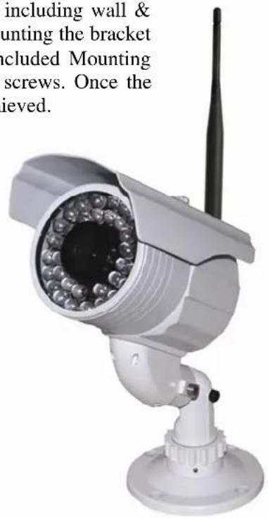
text_image
including wall & ounting the bracket cluded Mounting screws. Once the ieved.TIPS & TROUBLE SHOOTING
Snow on the Monitor
If there is snow or noise on your monitor this is a good indication that the receiver is receiving a weak signal.
To correct an image that has a lot of noise (snow) a number of things can be done.
- Move the transmitter and receiver closer together.
- Eliminate obstructions between the transmitter and receiver.
- Add a high gain antenna to the receiver end to increase receive sensitivity.
- Use a higher output power transmitter.
Interference
We strongly recommend that you always conduct a temporary setup of any wireless equipment before systems are permanently mounted. As we are sharing a radio frequency that is considered part of the public band, we do not have any entitlement to that frequency and must accept interference if it exists.
Examples of RF Interference
- Other 5.8GHz video transmitters in your area.
- 5.8GHz wireless data network, LAN or WAN.
• Proximity to some consumer products may be a source of interference.
Examples include: cordless phones, consumer data transceivers for wireless internet and Bluetooth devices.
Other Examples of Interference Not Related to Wireless
- Improper line-of-sight, installation or alignment of transmitters and receivers.
• Power source ground loops.
• Incorrect voltages to devices (too high or too low), including transmitters and receivers. - Sharing power supplies between devices.
- Power source is too close to video cable, low impedance, coax cable kinks, poor video cable terminations, improper and/or lengthy power source cabling.
Possible Solutions if Experiencing Interference
- Change the channel of your transmitter or move your wireless video devices farther away from the source of interference. Transmitters do not have to be beside the camera source and the receivers do not have to be beside the monitoring equipment.
- Before connecting the video feed into the transmitter, use a field monitor to check that you have a good video picture. Similarly for the receiver, check the video output first before connecting to the video feed into the monitor or recorder.
• Depending on the installation, use an existing building as a shield from interfering sources.

natural_image
Aerial view of a busy urban intersection with multiple lanes of cars, traffic, and green spaces (no visible text or signage)
natural_image
Exterior view of a large parking lot filled with parked cars under streetlights (no signage or text visible)


| ZX-580SR120 | ZX-580SR200 | ZX-580SR240 | |
| FREQUENCY | 5.725GHz – 5.875GHz; 8 User Selectable Channels | ||
| RADIATED POWER | 50mV/m @ 3m | ||
| 300 Feet up to 4 Miles Depending on Optional Receiver & Antenna (Sold Separately) | |||
| RANGE (LINE-OF-SIGHT) | |||
| ANTENNA TYPE | 3dB Omni-Directional Rubber Duck | ||
| VIDEO FORMAT | NTSC | ||
| CAMERA TYPE | 1/3" Day/Night Sony CCD | ||
| RESOLUTION | 580 Lines | ||
| 4.0mm - 9.0mm | 4.0mm-9.0mm | 15-50mm | |
| LENS TYPE | Varifocal Lens | Varifocal Lens | Varifocal Lens |
| INFRARED Up to 120 Feet | Up to 200 Feet | Up to 240 Feet | |
| 0.003 LUX @ F1.2 | 0.003LUX @ F1.2 | 0.0006LUX @ F1.2 | |
| MINIMUM ILLUMINATION | |||
| CONSTRUCTION Rugged All-Weather IP-66 Rated Cast Aluminum Design | |||
| TEMPERATURE RANGE | -30°F to +170°F | ||
| OPERATING VOLTAGE | 12VDC Model # PS-121A | ||
| CURRENT CONSUMPTION | 250mA IR OFF / 500mA IR ON | 300mA IR OFF / 500mA IR ON | 320mA IR OFF / 1,000mA IR ON |
| MOUNTING BRACKETS Universal 3 Axis Mounting Bracket | |||
| WEIGHT 840g or 1.8 lbs | 840g or 1.8lbs | 1,000g or 2.2lbs | |
| FCC APPROVED Yes | |||

| CX-580SR120VIDEO FORMAT NTSCCAMERA TYPE 1/3" Day/Night Sony CCDRESOLUTION 580 LinesLENS TYPE4.0mm - 9.0mmVarifocal Lens4.0mm-9.0mmVarifocal Lens15-50mmVarifocal LensINFRARED Up to 120 FeetMINIMUM ILLUMINATION0.003 LUX @F1.2Up to 200 Feet0.003LUX @F1.2Up to 240 Feet0.0006LUX @F1.2CONSTRUCTION Rugged All-Weather IP-66 Rated Cast Aluminum DesignTEMPERATURE RANGE -30°F to +170°FOPERATING VOLTAGE 12VDC Model # PS-121ACURRENT 250mA IR OFF / 500mA IR ON300mA IR OFF / 500mA IR ON320mA IR OFF / 1,000mA IR ONMOUNTING BRACKETS Universal 3 Axis Mounting BracketWEIGHT 840g or 1.8 lbsFCC APPROVED Yes840g or 1.8lbs1,000g or 2.2lbs | CX-580SR200 | CX-580SR240 |
| 840g or 1.8lbs1,000g or 2.2lbs |
WARRANTY INFORMATION/ TERMS & CONDITIONS
VideoComm Technologies, herein referred to as "VCT."
LIMITED WARRANTY
VCT hereby warrants, subject to the conditions here in below, that should this product become defective by reason of improper workmanship or material defect during the specified warranty period, VCT will repair the same, affecting all necessary parts without charge for either parts or labor, or replace the unit at VCT option.
Labor: ONE (1) Year from the date of original purchase from authorized Re-seller. TWO (2) Years for Antennas only.
Parts: ONE (1) Year from the date of original purchase from authorized Re-seller. TWO (2) Years for Antennas only.
Void Warranty
Purchaser warranty will be void and purchaser waves any rights to make warranty claim if product has been opened, altered or modified, repaired or serviced by anyone, other than the service facilities authorized by VCT to render such services. Further, the seal/serial number on the unit must not have been altered or removed. The unit must not have been subject to accident, misuse, abuse or operated contrary to the instructions provided. The opinion of VCT with respect to this matter shall be final. This warranty does not include and is not extended to broken and damaged accessories, batteries and exposed antennas and to parts wearing out due to normal wear and tear.
Proper Delivery:
Returned products will not be accepted for warranty repair unless accompanied with a valid Return Merchandise Authorization (RMA) number issued by VCT. RMA numbers issued by VCT are valid for 15 days. Shipments received after 15 days will be refused. The unit must be shipped, freight prepaid or delivered to the VCT Service facility, in either its original package or similar package, affording an equal degree of protection and with instructions indicating the location within Canada or the United States to which the unit will be returned. The repaired unit will be returned to the customer freight prepaid unless the warranty claim is deemed void or invalid. All accessories included with the unit must be listed individually on the packing slip for the shipping documentation. VCT will not accept any liability, for loss or damage to such accessories if they are not listed.
Proof of Purchase Date:
This warranty applies and commences to VCT products, from the original date of purchase from an Authorized Re-seller. Proof of purchase (i.e.: photocopy of invoice), must be included with product when submitting for warranty repair.
Warranty Limitations:
This warranty does not cover maintenance or check-ups, if required. This warranty gives you specific legal rights and you may also have other rights, which vary from state/province to state/province. Some states/provinces do not allow the exclusion or limitation of incidental or consequential damages or limitations on how long an implied warranty lasts, therefore the above exclusions or limitations may not apply to you. VCT is not responsible or liable for indirect, special, incidental or consequential damages arising out of or in connection with, the use or performance of the product or other damages with respect to loss of property, loss of revenues or profit, or cost of removal, installation or reinstallation.
PRODUCT RETURNS
30 Day Product Return Policy ** If you are not satisfied with a product, you may return it to VCT within 30 days from original date of shipment within the following conditions:
♦ Original shipping charges are not refundable unless deemed that VCT shipped incorrect item(s), incorrect quantity (ies) or original manufacturers defective product (subject to VCT validation).
◆ Returned products will not be accepted unless accompanied with a valid Return Merchandise Authorization number (RMA).
◆ RMA numbers issued by VCT are valid for 15 days. Shipments received after 15 days will be refused.
◆ Returns must include a copy of original invoice, the completed VCT packing slip, and a detailed statement of reason for return.
◆ Customer is responsible for all freight charges, duties and taxes, if applicable. Product must be properly packaged and shipped, prepaid to VCT in its original packaging, or similar packaging that offers an equal degree of protection. VCT will charge the full replacement cost for any missing components or parts. VCT is not responsible for lost or damaged merchandise. We strongly recommend insuring products for return shipping.
Return claims are void if manufacturer's seal is broken and/or products are altered or modified, subjected to an accident, improper handling, improper installation, misuse and abuse or operated contrary to the operating instructions. Products returned that are not in "re-saleable" condition will be returned to customer at their expense.
♦ Discontinued items, special or custom-made equipment items (items not carried as stock even though they may appear on price lists) may not be returned. Returned products will be evaluated at the original purchase price and not at any subsequent price increase or decrease.
** Subject to the conditions stated above, the following re-stocking fees will apply to products returned for credit/refund. VCT reserves the right to determine the validity of the product returned and / or refuse to accept product for credit.
0 % Re-Stocking Fee (less original shipping charges): If product is returned within 30 days from original VCT ship date.
25% Re-Stocking Fee (less original shipping charges): If product is returned within 60 days from original VCT ship date.
50% Re-Stocking Fee (less original shipping charges): If product is returned within 90 days from original VCT ship date.
100% Re-Stocking Fee (0% credit): If product is returned after 90 days from original VCT ship date.
DISCLAIMER
In no event will VCT or any of its affiliates be liable for any indirect, special, punitive, consequential liability, or incidental damages upon any basis of liability whatsoever even if advised of the possibility of such damages. In addition, VCT does not take any responsibility or assume any liability for the wiring, installation or placement of the equipment Customer purchases, or for the activities of any other individual or entity such as Customer's Company, those who prepare the specifications or any local Authorities who inspect or approve Customer's installation.