57ST-ACC-AU - Heating Quadra-Fire - Free user manual and instructions
Find the device manual for free 57ST-ACC-AU Quadra-Fire in PDF.

User questions about 57ST-ACC-AU Quadra-Fire
0 question about this device. Answer the ones you know or ask your own.
Ask a new question about this device
Download the instructions for your Heating in PDF format for free! Find your manual 57ST-ACC-AU - Quadra-Fire and take your electronic device back in hand. On this page are published all the documents necessary for the use of your device. 57ST-ACC-AU by Quadra-Fire.
USER MANUAL 57ST-ACC-AU Quadra-Fire
Installation & Appliance Set-Up
INSTALLER: Leave this manual with party responsible for use and operation.
OWNER: Retain this manual for future reference.
NOTICE: DO NOT DISCARD THIS MANUAL
QUADRA-FIRE
5700 STEP TOP
AUSTRALIA
WOOD APPLIANCE
AUTOMATIC COMBUSTION CONTROL
(ACC)
MODEL:
57ST-ACC-AU

natural_image
Illustration of a portable stove with open door and side-mounted vent (no text or symbols)
natural_image
Illustration of a simple wood oven with lid, vent, and side legs (no text or symbols)
WARNING
If the information in these instructions is not followed exactly, a fire could result causing property damage, personal injury, or death.
- Do not store or use gasoline or other flammable vapors and liquids in the vicinity of this or any other appliance.
- Do not over fire - If appliance or chimney connector glows, you are over firing. Over firing will void your warranty.
- Comply with all minimum clearances to combustibles as specified. Failure to comply may cause house fire.

WARNING
HOT SURFACES!
Glass and other surfaces are hot during operation AND cool down.

Hot glass and appliance will cause burns.
- Do not touch glass until it is cooled
• Use leather gloves when reloading fuel
• NEVER allow children to touch glass - Keep children away
- CAREFULLY SUPERVISE children in same room as appliance.
- Alert children and adults to hazards of high temperatures
• High temperatures may ignite clothing or other flammable materials. - Keep clothing, furniture, draperies and other flammable materials away.

WARNING
Fire Risk.
For use with solid wood fuel only.
Other fuels may over fire and generate poisonous gases (i.e. carbon monoxide).
Safety Alert Key:

• DANGER! Indicates a hazardous situation which, if not avoided will result in death or serious injury.
• WARNING! Indicates a hazardous situation which, if not avoided may result in death or serious injury.
• CAUTION! Indicates a hazardous situation which, if not avoided, may result in minor or moderate injury.
- NOTICE: Indicates practices which may cause damage to the appliance or to property.
TABLE OF CONTENTS
1 Important Safety Information......3
A. Appliance Certification.... 3
B. BTU & Efficiency Specifications 3
C. Glass Specifications 3
D. Non-Combustible Materials.... 3
E. Combustible Materials.... 3
2 Getting Started....4
A. Design and Installation Considerations ..... 4
B. Fire Safety 4
C. Negative Pressure.... 4
D. Tools And Supplies Needed 5
E. Inspection of Appliance and Components ..... 5
F. Removal of Appliance from Shipping Materials .... 5
G. Install Checklist 6
3 Dimensions and Clearances......7
A. Appliance Dimensions 7
B. Hearth Protection Requirements 8
C. Firebox Installation 8
D. Clearances to Combustibles ..... 9
4 Chimney Systems....10
A. Locating Your Appliance & Chimney ..... 10
B. Minimum Height of Flue System Exit ..... 11
C. Chimney Termination Requirements ..... 12
D. General Flue System Instructions ..... 13
E. Chimney Height / Rise and Run 13
F. Installing Chimney Components ..... 13
G. Proper Draft 13
H. Tested Flue Systems.... 14
I. Un-Tested Flue Systems.... 15
5 Appliance Set-Up 16
A. Pedestal Assembly & Ash Removal System Installation 16
B. Access Cover Handle 18
C. Leg Kit & Ash Removal System Installation ..... 18
D. Door Handle Assembly 19
E. Outside Air Kit Installation 20
6 AS/NZS 2918:2001 General Notes ...21
7 Reference Materials....22
A. Service and Maintenance Log. 22
B. Accessory List 23
1
Important Safety Information
A. Appliance Certification
| Model: | 5700 Step Top AU Wood Appliance |
| Laboratory: | Vipac |
| Report No: | 30A-14-0102-TRP-361517-0 |
| Type: | Hardwood only at 25% dry basis |
| Standard: | AS/NZS4013 for Hardwood |
B. BTU & Efficiency Specifications
| Overall Average Efficiency Burning Hardwood (AS/NZS 4012) | 65% |
| Average Particulate Emission Factor Burning Hardwood (AS/NZS 4013) | 1.5 g/kg |
| Maximum Average Heat Output Burning Hardwood | 12.7 kW |
| Wetback | Wetbacks are NOT an approved option and must be fitted. |
| Vent Size: | 6 inches |
| Firebox Size: | 2.90 cubic feet |
| Recommended Wood Length: | 22 inches |
| Fuel Orientation: | Front-to-Back |
| Approved Fuel | Hardwood only with a Moisture content less than 25% (dry basis) |
C. Glass Specifications
This appliance is equipped with 5mm ceramic glass.
Replace glass only with 5mm ceramic glass. Please contact your dealer for replacement glass.
Improper installation, adjustment, alteration, service or maintenance can cause injury or property damage.
For assistance or additional information, consult a qualified installer, service agency or your dealer.
Hearth & Home Technologies WILL NOT warranty appliances that exhibit evidence of over-firing. Evidence of over-firing includes, but is not limited to:
- Warped air tube
• Deteriorated refractory brick retainers
• Deteriorated baffle and other interior components
D. Non-Combustible Materials
Material which will not ignite and burn, composed of any combination of the following:
- Steel - Concrete
- Plaster - Tile
- Brick - Glass
- Iron - Slate
E. Combustible Materials
Material made of/or surfaced with any of the following materials:
- Wood - Plastic
- Compressed Paper - Plywood/OSB
- Plant Fibers - Sheet Rock (drywall)
Any material that can ignite and burn: flame proofed or not, plastered or non-plastered.
NOTE: Hearth & Home Technologies, manufacturer of this appliance, reserves the right to alter its products, their specifications and/or price without notice.
The Quadra-Fire 5700 Step Top Australian Wood Appliance is Hardwood Certified. Hardwood Particulate Emissions equaling 1.5 g/kg with a Space Heating Efficiency of 65%.
This wood appliance needs periodic inspection and repair for proper operation. It is against federal regulations to operate this wood appliance in a manner inconsistent with operating instructions in this manual.
Install Guide
2 Getting Started
A. Design and Installation Considerations
Consideration must be given to:
- Safety
- Convenience
- Traffic flow
• Chimney and chimney connector required
It is a good idea to plan your installation on paper, using exact measurements for clearances and floor protection, before actually beginning the installation. If you are not using an existing chimney, place the appliance where there will be a clear passage for a factory-built listed chimney through the ceiling and roof.
We recommend that a qualified building inspector and your insurance company representative review your plans before and after installation.
If this appliance is in an area where children may be near it is recommended that you purchase a decorative barrier to go in front of the appliance. Remember to always keep children away while it is operating and do not let anyone operate this appliance unless they are familiar with these operating instructions.

CAUTION
Check building codes prior to installation.
- Installation MUST comply with local, regional, state and national codes and regulations.
- Consult insurance carrier, local building, fire officials or authorities having jurisdiction about restrictions, installation inspection, and permits.

WARNING
Asphyxiation Risk.
- Do NOT connect this appliance to a chimney flue servicing another appliance.
- Do NOT connect to any air distribution duct or system.
May allow flue gases to enter the house.
NOTICE
Hearth & Home Technologies assumes no responsibility for the improper performance of the appliance system caused by:
- Inadequate draft due to environmental conditions
- Down drafts
- Tight sealing construction of the structure
- Mechanical exhausting devices
• Over drafting caused by excessive chimney heights - Ideal performance is with height of chimney between 14-16 feet (4.26-4.88m) measured from the base of the appliance.
B. Fire Safety
To provide reasonable fire safety, the following should be given serious consideration:
-
Install at least one smoke detector on each floor of your home to ensure your safety. They should be located away from the heating appliance and close to the sleeping areas. Follow the smoke detector manufacturer's placement and installation instructions, and be sure to maintain regularly.
-
A conveniently located Class A fire extinguisher to contend with small fires resulting from burning embers.
-
A CO detector should be installed in the room with the appliance.
-
A practiced evacuation plan, consisting of at least two escape routes.
-
A plan to deal with a chimney fire as follows:
-
In the event of a chimney fire: a. Evacuate the house immediately b. Notify fire department.
C. Negative Pressure

WARNING
Asphyxiation Risk.
- Negative pressure can cause spillage of combustion fumes, soot and carbon monoxide.
- Appliance needs to draft properly for safety.
Negative pressure results from the imbalance of air available for the appliance to operate properly. It can be strongest in lower levels of the house.
Causes include:
- Exhaust fans (kitchen, bath, etc.)
- Range hoods
- Combustion air requirements for furnaces, water appliances and other combustion appliances
- Clothes dryers
- Location of return-air vents to furnace or air conditioning
- Imbalances of the HVAC air handling system
• Upper level air leaks such as:
- Recessed lighting
- Attic hatch
- Duct leaks
To minimize the effects of negative air pressure:
• Install optional outside air kit with the intake facing prevailing winds during the heating season
- Ensure adequate outdoor air for all combustion appliances and exhaust equipment
- Ensure furnace and air conditioning return vents are not located in the immediate vicinity of the appliance
- Avoid installing the appliance near doors, walkways or small isolated spaces
- Recessed lighting should be a "sealed can" design
- Attic hatches weather stripped or sealed
- Attic mounted duct work and air handler joints and seams taped or sealed
- Basement installations should be avoided

WARNING
Fire Risk.
Hearth & Home Technologies disclaims any responsibility for, and the warranty will be voided by, the following actions:
• Installation and use of any damaged appliance.
- Modification of the appliance.
• Installation other than as instructed by Hearth & Home Technologies.
• Installation and/or use of any component part not approved by Hearth & Home Technologies.
- Operating appliance without fully assembling all components.
- Operating appliance without legs attached (if supplied with appliance).
- Do NOT Over fire - If appliance or chimney connector glows, you are over firing.
Any such action that may cause a fire hazard.
D. Tools And Supplies Needed
Before beginning the installation be sure the following tools and building supplies are available:
| Reciprocating saw | Framing material |
| Pliers | High temp caulking material |
| Hammer | Gloves |
| Phillips screwdriver | Framing square |
| Flat blade screwdriver | Electric drill and bits |
| Plumb line | Safety glasses |
| Level | Tape measure |
| Misc. screws and nails | 7/16 socket or wrench |
| 1/2-3/4 in. length, #6 or #8 self-drilling screws | |
E. Inspection of Appliance and Components
- Remove appliance and components from packaging and inspect for damage.
• Report to your dealer any parts damaged in shipment. - Read all the instructions before starting the installation. Follow these instructions carefully during the installation to ensure maximum safety and benefit.
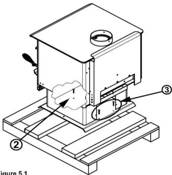
F. Removal of Appliance from Shipping Materials
- Remove box and 51mm x 102mm structural boards being careful not to damage product.
- Using 7/16 socket or wrench remove one bolt located inside front part of appliance (Figure 5.1).
- Moving to the back of the appliance and using 7/16 socket or wrench remove two bolts (Figure 5.1).
- Carefully pull appliance off of pallet and put in desired location following Hearth Pad and Clearance to Combustibles on pages 8 and 9.
text_image
figure 5.1 ② ③Figure 5.1

WARNING
Fire Risk.
Inspect appliance and components for damage. Damaged parts may impair safe operation.
- Do NOT install damaged components.
- Do NOT install incomplete components.
- Do NOT install substitute components.
Report damaged parts to dealer.
G. Install Checklist
ATTENTION INSTALLER:
Follow this Standard Work Checklist
This standard work checklist is to be used by the installer in conjunction with, not instead of, the instructions contained in this installation manual.
Customer:
Date Installe:
Lot / Address:
Location of Appliance:
Installer:
Dealer / Distributor Phone #:
Serial #:
Model:
WARNING! Risk of Fire or Exposion! Failure to install appliance according to these instruction can lead to a fire or explosion.
Appliance Install
Verified clearances to combustibles.
Appliance is leveled and connector is secured to appliance.
Hearth extension size/height decided.
Outside air kit installed.
Floor protection requirements have been met.
If appliance is connected to a masonry chimney, it should be cleaned and inspected by a professional. If installed to a factory built metal chimney, the chimney must be installed according to the manufacturer's instructions and clearances.
Chimney
Chimney configuration complies with diagrams.
Chimney installed, locked and secured in place with proper clearance.
Chimney meets recommended height requirements (14-16 feet).
Roof flashing installed and sealed.
Terminations installed and sealed.
Clearances
Combustible materials not installed in non-combustible areas.
Verified all clearances meet installation manual requirements.
Mantels and wall projections comply with installation manual requirements.
Protective hearth strips and hearth extension installed per manual requirements.
Appliance Setup
All packaging and protective materials removed.
Firebrick, baffle and ceramic blanket installed correctly.
All labels have been removed from the door.
All packaging materials are removed from inside/under the appliance.
Manual bag and all of its contents are removed from inside/under the appliance and given to the party responsible for use and operation.
YES IF NO, WHY?


Hearth & Home Technologies recommends the following:
• Photographing the installation and copying this checklist for your file.
- That this checklist remain visible at all times on the appliance until the installation is complete.
Comments: Further description of the issues, who is responsible (Installer/Builder/Other Trades, etc.) and corrective action needed:
Comments communicated to party responsible ____ by ____ on ____
(Builder / Gen. Contractor) (Installer) (Date)
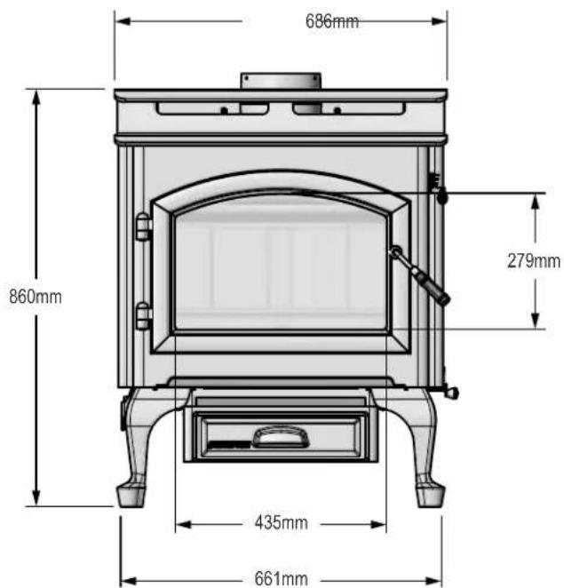
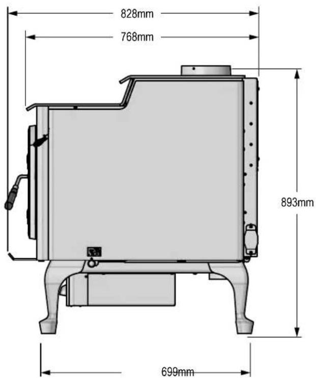
3 Dimensions and Clearances
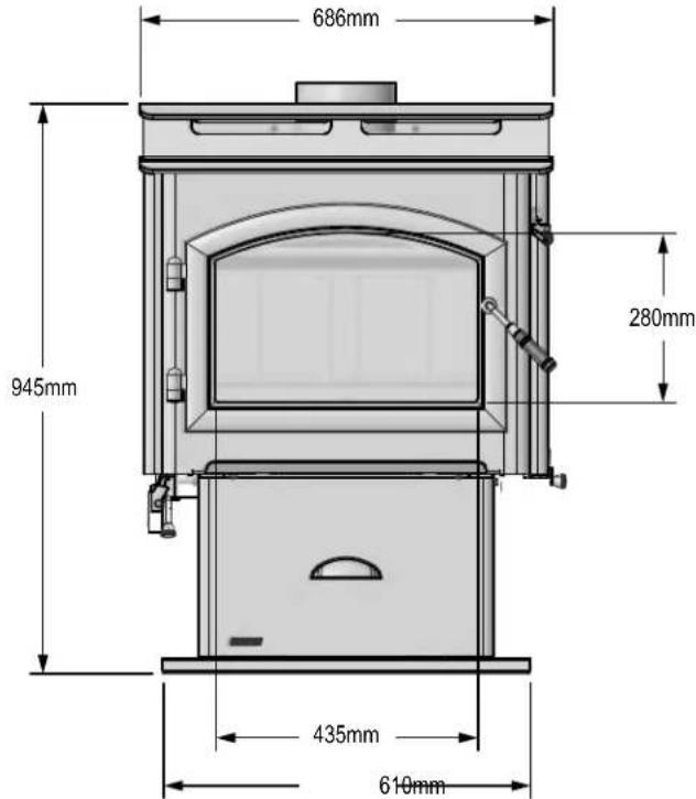
A. Appliance Dimensions
text_image
686mm 945mm 280mm 435mm 610mmFigure 7.1 - Front View
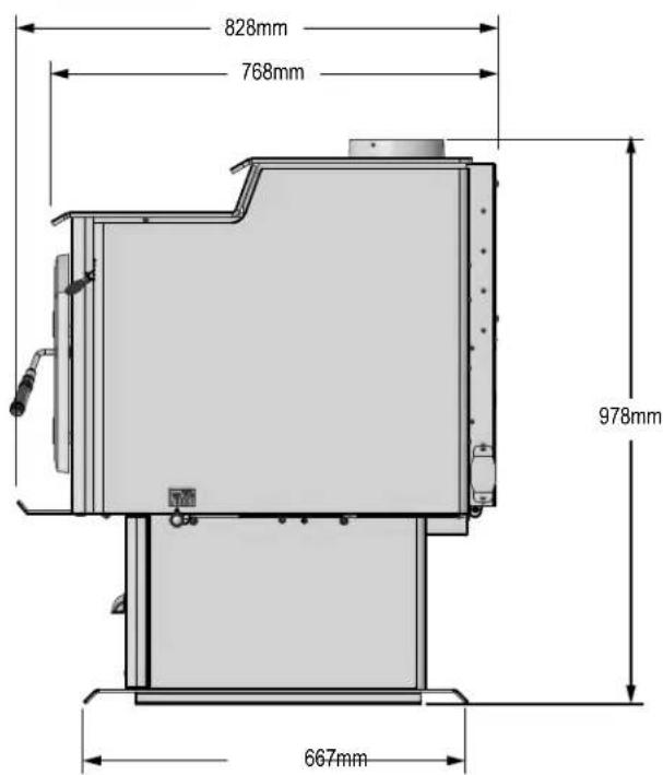
text_image
828mm 768mm 978mm 667mmFigure 7.2 - Side View
NOTE: Flue Collar size is 152mm inside diameter (ID)
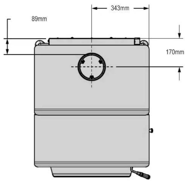
text_image
89mm 343mm 170mmFigure 7.3 - Top View
Appliance Dimensions Continued
text_image
686mm 279mm 860mm 435mm 661mmFigure 8.1 - Front View
text_image
828mm 768mm 893mm 699mmFigure 8.2 - Side View
B. Hearth Protection Requirements
Quadra-fire 5700 Step Top ACC do not require a insulating Floor Protector, as they are tested and comply with the minimum Floor Protector requirements of AS/NZS 2918:2001.

NOTE
- The minimum Floor Protector sizes are specified in the clearance chart, see Figures 9.1 and 9.2 on page 9.
- A Floor Protector can include ceramic tiles with grouted joints fixed directly onto a wooden floor or a sheet of toughened glass, panel steel or any other non combustible material laid directly onto a wooden floor.
- If installed directly onto a concrete slab, the concrete slab can be considered as the floor protector, but must maintain the minimum measurement listed.

WARNING
Fire Risk.
Hearth pads must be installed exactly as specified. High temperatures or hot embers may ignite concealed combustibles.

WARNING
Fire Risk.
- Comply with all minimum clearances to combustibles as specified.
- Failure to comply may cause house fire.
C. Firebox Installation
- If a separate floor protector is being used position now. Place the firebox on the floor protector to suit the minimum installation clearances (Figures 9.1 and 9.2 on page 9).
- Systemically restrain the firebox and the floor protector to the floor.
- Fit 2mm x 6mm fixings suitable for the floor material. DO NOT over tighten.
- Fit timber trim pedestal edging to front and back of base (optional).
D. Clearances to Combustibles
| MINIMUM CLEARANCES TO COMBUSTIBLE MATERIALS in MillimetersNote: A, C, and F Dimensions are to the center of the flue collar5700 Step Top AU Wood Appliance | ||||||||||||
| INSTALLATION | ||||||||||||
| A | B | C | D | E | F | G | H | I | J | K | ||
| DOUBLE WALL PIPE | 370 | 200 | 673 | 330 | 76 | 100 | 850 | 14 | 10 450 | 910 | 905 | |

text_image
REAR WALL C E D SIDE WALL FLOOR PROTECTOR G HFigure 9.1
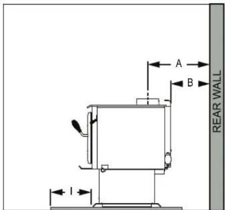
text_image
A B I REAR WALLFigure 9.2

text_image
CORNER WALL CORNER WALL FLOOR PROTECTOR L K F J GFigure 9.3
NOTE: Service Space
In order to replace the tube channel assembly a clearance of 483mm is required on the right side of appliance in order to remove the tubes with the appliance in place.
If space is not available, the appliance will have to be disconnected from the chimney to proceed with the tube replacement.
4 Chimney Systems
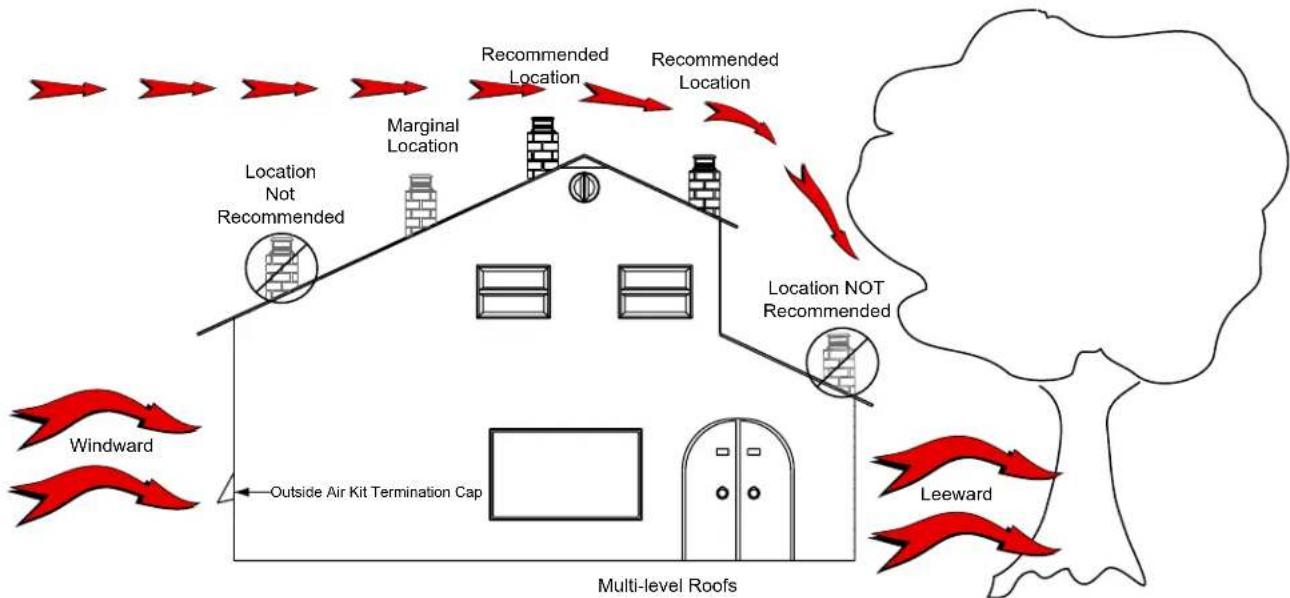
A. Locating Your Appliance & Chimney
Location of the appliance and chimney will affect performance. As shown in Figure 10.1 the chimney should:
- Install through the warm space enclosed by the building envelope. This helps to produce more draft, especially during lighting and die down of the fire.
- Penetrate the highest part of the roof. This minimizes the affects of wind turbulence and down drafts.
- Consider the appliance location in order to avoid floor and ceiling attic joists and rafters.
- Locate termination cap away from trees, adjacent structures, uneven roof lines and other obstructions. Your local dealer is the expert in your geographic area and can usually make suggestions or discover solutions that will easily correct your flue problem.
flowchart
graph TD
    A["Multi-level Roofs"] --> B["Location Not Recommended"]
    B --> C["Marginal Location"]
    C --> D["Location Not Recommended"]
    D --> E["Recommended Location"]
    E --> F["Recommended Location"]
    F --> G["Location NOT Recommended"]
    G --> H["Leeward"]
    I["Windward"] --> J["Outside Air Kit Termination Cap"]
    K["Red Windward"] --> L["Red Windward"]
    M["Red Leeward"] --> N["Red Leeward"]
Figure 10.1
B. Minimum Height of Flue System Exit

text_image
3000mm 3000mm or less more than 3000mm 600mm minimum 3000mm increase from 1000mm minimum until clear within 3000mm of flue top increase as necessary until nothing within 3000mm of fluetop any nearby structureFigure 11.1
NOTICE:
• Chimney performance may vary.
- Trees, buildings, roof lines and wind conditions affect performance.
- Chimney height may need adjustment if smoking or overdraft occurs.
NOTICE:
Locating the appliance in a basement or in a location of considerable air movement can cause intermittent smoke spillage from appliance. Do not locate appliance near
- Frequently open doors
• Central heat outlets or returns
C. Chimney Termination Requirements
- Flue pipe installed crimp/narrow end down
- Outer casings installed crimped/narrow end up. (Critical when exposed above the roof)
- Inner casings:
- direction not critical
- Flue pipes:
- seal all joints including firebox spigot.
- fix with a minimum of 3 stainless steel rivets
- Flue pipe spacers:
- affix to flue pipe
- Flue system termination point:
- Refer to AS/NZS 2918:2001 4.9.1, see Figure 15.2 on page 15.
- Flue pipe shall extend not less than 4.6m above top of the floor protector as per AS/NZS 2918:2001 4.9.1(a)
- Facade or chase systems:
- same rule applies as above.
- Roof penetration and flashing method refer to NZ Building Code E2.(From 01/07/05)
NOTE: These instructions apply to 150mm diameter flue pipe systems as tested to AS/NZS 2918:2001
-
Either locate the appliance in position or by measuring at the ceiling mark the flue pipe center position. Check that the outer casing is unobstructed through the attic space or roof area.
-
Spike the center with a nail. Transfer this position to the next surface above. Plumb bob/laser.
-
Cut out the ceiling penetration hole – square or rectangle – short axis equals outer casing diameter plus 50mm, long axis as required. See Tested Flue System on page 14 and Un-Tested Flue System on page 15. Perform the same at the roof penetration.
-
Frame out the hole with minimum 75mm x 50mm timber or as required for roofing material. Minimum requirement at roof penetration see NZ Building Code E2 Acceptable Solution (from 01/07/05).
-
Install the outer casing so that:
i. lower end is flush with the underside of the ceiling material and
ii. with the addition of metal "L" brackets, affix to the outer casing at 90 degrees secure the outer casing centrally to the ceiling and roof nogs. Alternatively substitute the "L" brackets for 25mm thick non heat sensitive packers. Secure the outer casing through the packers with horizontal fixings to the nogs. Refer to the General Flue System Instructions on page 13 for termination height. The option of outer casing slips to be taken into account.
-
Flash the outer casing to the roof material with the appropriate approved flashing.
-
If using an outer/inner casing combination, now install the inner casing ensuring it extends a minimum 200mm above the high side of the roof penetration. If not using a combination see '11' below.
-
Refer to steps 1 and 2 under Firebox Installation on page 8.
-
Prepare the ceiling plate and place upside down over the flue spigot.
-
Install the flue pipes by preferred method – either up or down the outer casing. Affix each length per the notes in General Instructions (above). Extend the flue pipe above the outer casing to suit the casing cover/cowl assembly.
-
If the inner casing has not been installed, install now. Refer to step 7 on page 12 for minimum height.
-
Install the cowl assembly, i.e. Top spacer, casing cover and cowl.
-
Position and secure the ceiling plate with the screws and spacers.
-
Wipe the flue pipe to remove finger marks.
-
Refer to step 3 under Firebox Installation on page 8.
-
If flue offset is required, refer to AS/NZS 2918:2001 4.1

WARNING
Asphyxiation Risk.

- DO NOT CONNECT THIS Appliance TO A CHIMNEY FLUE SERVICING ANOTHER APPLIANCE.
- DO NOT CONNECT TO ANY AIR DISTRIBUTION DUCT OR SYSTEM.
May allow flue gases to enter the house.

WARNING
Improper installation, adjustment, alteration, service or maintenance can cause injury or property damage. Refer to the owner's information manual provided with this appliance. For assistance or additional information consult a qualified installer, service agency or your dealer.

WARNING
Fire Risk.
Follow Chimney Connector Manufacturer's Instructions for Proper Installation.
ONLY use connector:

- Within the room, between appliance and ceiling or wall.
- Connector shall NOT pass through:
- Attic or roof space
- Closet or similar concealed space
- Floor or ceiling
Maintain minimum clearances to combustibles
D. General Flue System Instructions
- Unpack the Flue Mounted Shield, detach the three brackets and familiarize yourself with the illustrations.
- Using a sharp knife or razor blade, carefully cut through the plastic film on the "inside face" where it meets the outer shield (refer sketch). Cut along the full length of the Flue Mounted Shield on both side, then peel off and fully remove the plastic film from the stainless steel inner shield.
- Peel back and fully remove the plastic film from the outer shield.
- Fit the top bracket to the Flue Mounted Shield as illustrated ensuring the rear mid section of the bracket fits "outside" while the two outer sections of the bracket fit "inside".
- Fit the appropriate lower bracket to your wood fire.
Lower Bracket "5B suitable for all other wood fires without an inner rear heat shield. On certain model wood fires without a raised flue spigot it will be necessary to cut off both the lower outer legs from the bracket "5B" leaving the entral tongue to locate inside the flue outlet only.
Two tabs are provided and if folded back at 90 degrees the bracket and Flue Mounted Shield will mount lower onto the appliance.
The Flue Mounted Shield then locates into the two notches provided n bracket "5B" as illustrated.
- Once the Flue Mounted Shield is fitted in position onto either of the two lower mounting brackets, check to ensure a large gap is not present between the top of the wood fire and the base of the Flue Mounted Shield, as this may result in a hot spot on the rear wall directly behind the flue outlet. If your wood fire has a lift off top grill the Flue Mounted Shield should be raised sufficiently to enable the top grill to be removed.
- Using the pre-punched holes in the two tabs provided on the top bracket as guides, drill into the flue pipe and secure the top bracket to the flue pipe with two stainless steel rivets (not supplied).
E. Chimney Height / Rise and Run
This product was designed for and tested on a 152mm chimney, 427-488cm high, (includes appliance height) measured from the base of the appliance. The further your stack height or diameter varies from this configuration, the greater the likelihood it may affect performance.
Chimney height may need to be increased by 2 - 3% per each 305 meters above sea level. It is not recommended to use offsets or elbows at altitudes above 1219 meters above sea level or when there are other factors that affect flue draft.
WARNING

Fire Risk.
Do NOT pack insulation or other combustibles between spacers.
- ALWAYS maintain specified clearances around venting and spacers.
• install spacers as specified.
Failure to keep insulation or other material away from vent pipe may cause fire.
F. Installing Chimney Components Chimney Connector
Single wall connector or appliance pipe:
This must be at least 24 gauge mild steel or 26 gauge blue steel. The sections must be attached to the appliance and to each other with the crimped (male) end pointing toward the appliance. All joints, including the connection at the flue collar, should be secured with 3 sheet metal screws. Make sure to follow the minimum clearances to combustibles.
Factory-built listed chimney connector (vented):
The listed connectors must conform to each other to ensure a proper fit and seal.

text_image
Crimped End Toward Appliance Flue Gas Direction Secure pipe sections with a minimum of 3 screwsFigure 13.1 - Chimney Connector (Appliance Pipe)
G. Proper Draft
To be sure that your Quadra-Fire insert burns properly, the chimney draft (static pressure) should be approximately -2.54mm water column (W.C.) during a high burn and -1.016mm W.C. during a low burn, measured 152mm above the top of the insert after one hour of operation at each burn setting.
H. Tested Flue Systems, as per AS/NZS 2918:2001

text_image
ADD Cowl Casing Cover oversized casing cover is necessary Spider Bracket Non combustible material Hebel block or 12mm Promina board or similar under the flashing Approved Flashing Roof Line Inner Casing 200mm above roof line Outer Casing Inner Casing Internal Swage 25 25 25 25 12 12.5 Vented Ceiling Plate Flue Pipe Floor Protector minimum 25mm gap between flue pipe casing & combustible materialFigure 14.1
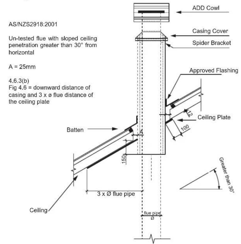
I. Un-Tested Flue Systems, as per AS/NZS 2918:2001, 4.6.3(b)
text_image
AS/NZS2918:2001 Un-tested flue with sloped ceiling penetration greater than 30° from horizontal A = 25mm 4.6.3(b) Fig 4.6 = downward distance of casing and 3 x Ø flue distance of the ceiling plate Batten Ceiling 150 3 x Ø flue pipe flue pipe Ø ADD Cowl Casing Cover Spider Bracket Approved Flashing Ceiling Plate 12 100 Greater than 30°Figure 15.1

text_image
AS/NZS2918:2001 Un-tested flue with sloped ceiling penetration greater than 30° from horizontal A = 25mm 4.6.3(b) Fig 4.6 = 3 x Ø flue from active flue to heat sensitive surface Batten Ceiling ADD Cowl Casing Cover Spider Bracket Approved Flashing Ceiling Plate 100 3 x Ø flue pipe flue pipe Ø Greater than 30°Figure 15.2
5 Appliance Set-Up
A. Pedestal Assembly & Ash Removal System Installation
NOTE: The Ash Removal System, must be installed first before installing the pedestal.
Included in Kit:
ARS door assembly, ARS latch assembly, Pedestal, Ash Pedestal Drawer, ARS Channel, ARS Cover, and fastener package.
Tools Required:
7/16 socket wrench, 3/8 open end wrench, Phillips screw driver, and hammer.
Begin installing the ARS System.
- Remove leg mount brackets packaged inside of firebox and discard.
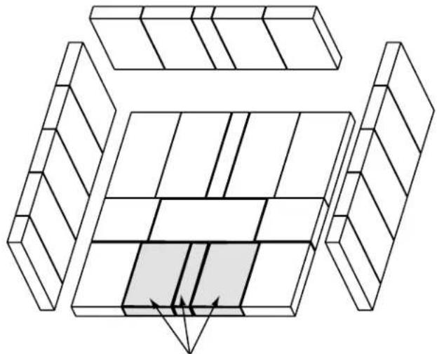
- Remove the 3 bricks in the front most part of the firebox (Figure 16.1).
- Lay appliance on its back on a protective pad or pallet (Figure 16.2).
- Remove heat shield by loosening the four bolts using 3/8 open end wrench (Figure 16.2).
- Remove 8 nuts that hold the cover plate on using a 7/16 socket wrench; discard cover plate (Figure 16.3).

WARNING
CHECK GASKET!
- Verify that the gasket is present and that the glossy side is away from firebox bottom.
-
It is important that the gasket is put in correctly for sealing capabilities.
-
Remove knock out from bottom of firebox by using a hammer (Figure 16.2).
-
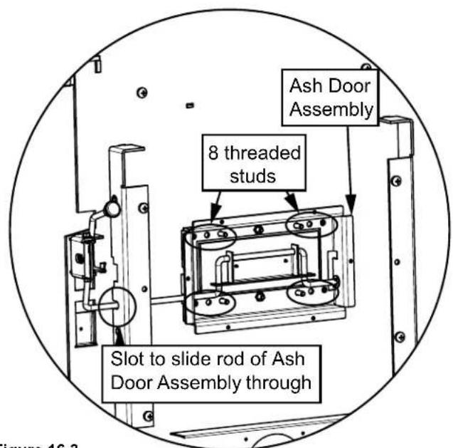
Install ash door assembly by sliding the rod at an angle into the slot on the left side (Figure 16.3).
-
Slide the ash door over the 8 screws protruding from the bottom of the appliance. Secure with nuts and washers using 7/16 socket wrench (Figure 16.3).
natural_image
Pure technical line drawing of a mechanical assembly with no text, numbers, or symbolsRemove 3 bricks for installation and then re-install
Figure 16.1

text_image
Loosen X4 Gasket ④ ⑦ ⑤ Remove X8 ⑥ Knock out Remove & discard ⑤ Heat shieldFigure 16.2
text_image
Ash Door Assembly 8 threaded studs Slot to slide rod of Ash Door Assembly throughFigure 16.3
- Install ARS latch by sliding latch assembly over 2 threaded studs protruding from the bottom on the left hand side of the appliance. Secure by using two nuts use 7/16 socket wrench.
- Add knob to handle rod (Figure 17.1).
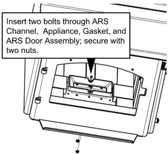
- Using two bolts and two flange nuts to secure ARS channel using 3/8 open end wrench and 7/16 socket wrench (Figure 17.2).

WARNING

Do NOT operate before fully assembling components. Burning your appliance without a pedestal or leg kit attached:
- Will void your warranty.
- May result in property damage or personal injury.

text_image
Door latch with the ash door rod locked in place Knob Ash Door Rod shown in installed positionFigure 17.1
text_image
Insert two bolts through ARS Channel, Appliance, Gasket, and ARS Door Assembly; secure with two nuts.Figure 17.2
Installing Ped Kit
- Follow Beginning installing the ARS system instructions provided on page 16.
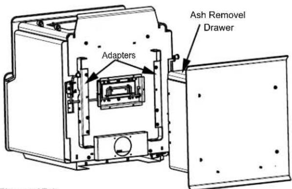
- Slide pedestal over adapter on bottom of appliance and secure with four screws using Phillips head screwdriver (Figure 17.3).
- Install ARS Spacer on left hand side with one bolt using Phillips head screwdriver (Figure 17.4).
- Carefully stand appliance up and place in desired location.
text_image
Adapters Ash Removal DrawerFigure 17.3

text_image
Ash Removal SpacerFigure 17.4
Finishing the ARS Installation
- Replace front 3 bricks that were removed in step 1 (Figure 18.1).
- Install the ash drawer to pedestal base.
- Install ARS access cover inside of ARS Channel that is located inside the firebox (Figure 18.1).

CAUTION
CHECK BAFFLE BOARDS & CERAMIC BLANKET!
- Verify that the baffle boards and ceramic blanket are in their proper locations.
- It is important that the baffle boards and ceramic blanket are in correctly installed for proper burn safety.
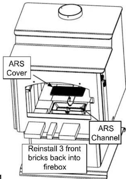
text_image
ARS Cover Reinstall 3 front bricks back into firebox ARS ChannelFigure 18.1
B. Access Cover Handle
Insert Access Cover Handle handle into slot of ARS Cover to remove ARS Cover for cleaning ash out of firebox (Figure 18.2).

natural_image
Technical line drawing of a mechanical bracket or panel assembly (no text or symbols)Figure 18.2
C. Leg Kit & Ash Removal System Installation
NOTE: The Ash Removal System, must be installed first before installing the legs.
Included in Kit:
ARS door assembly, ARS latch assembly, Ash Removal Box, Ash Removal Drawer, ARS Channel, ARS Cover, and fastener package.
Tools Required:
7/16 socket wrench, 9/16 socket wrench, 3/8 open end wrench, Phillips screw driver, and hammer.
Installing Queen Anne Leg ARS Kit
- Follow Beginning installing the ARS system instructions provided on page 16.
- Install ARS Spacer on left hand side with one bolt using Phillips head screwdriver (Figure 17.4 on page 17).
-
Install leg brackets and ash drawer using four screws and Phillips head screwdriver:
-
Start bottom two bolts through ash drawer, leg mount and into the bottom of the appliance (Figure 18.3).
-
Align top holes and repeat; secure all four bolts.
-
Install legs onto mounting brackets making sure the legs are up against the bracket and secure with bolts and washers using a 3/8 open end wrench (Figure 19.1 on page 19).
-
Install leveling bolts into 2 legs; these leveling legs should be in opposite corners (Figure 19.1 on page 19).
-
Carefully stand appliance up and place in desired location.
-
Use leveling bolts on legs to stabilize and level appliance (Figure 19.2 on page 19).
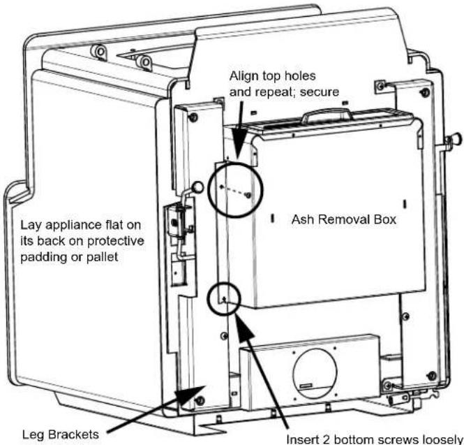
text_image
Lay appliance flat on its back on protective padding or pallet Align top holes and repeal; secure Ash Removal Box Leg Brackets Insert 2 bottom screws looselyFigure 18.3

text_image
Leveling Legs at Opposite CornersFigure 19.1

natural_image
Diagram of a mechanical assembly with a screw and directional arrows indicating motion (no text or symbols)Figure 19.2
text_image
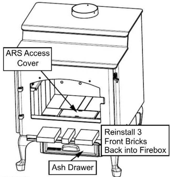
ARS Access Cover Reinstall 3 Front Bricks Back into Firebox Ash DrawerFigure 19.3
Finishing the ARS Installation
- Replace front 3 bricks that were removed (Figure 19.3).
- Install the ash drawer to ASH Removal.
- Install ARS access cover inside of ARS Channel that is located inside the firebox (Figure 19.3).

CAUTION
CHECK BAFFLE BOARDS & CERAMIC BLANKET!
- Verify that the baffle boards and ceramic blanket are in their proper locations.
- It is important that the baffle boards and ceramic blanket are in correctly installed for proper burn safety.
D. Door Handle Assembly
Install spring handle using a counter-clockwise motion until the spring handle has a 51mm clearance from bend of door hand rod (Figure 19.4).
51mm clearance is required from bend in door handle rod to end of spring handle
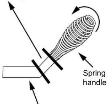
text_image
Spring handleFigure 19.4
E. Outside Air Kit Installation
A source of air (oxygen) is necessary in order for combustion to take place. Whatever combustion air is consumed by the fire must be replaced. Air is replaced via air leakage around windows and under doors. In homes that have tightly sealed doors and windows, an outside air source is needed. An optional Outside Air Kit is available. Included in OAK-ACC:
Termination cap, (2) wire ties, flex adapter, and fasteners Included in SRV7033-041:
Cover plate and sealing rope (see Floor Installation Alternative below, Figure 20.2)
Items Needed for Installation (not supplied)
- 102mm flex aluminum pipe, or if using alternate material, then it shall be made from durable, non-combustible, heat resistant material up to 350oF. Cut the pipe to the required length for your installation. - Phillips head screw driver - Silicone sealant - Drills and saws necessary for cutting holes through the wall or flooring in your home.
- Remove all materials from packing box.
- Using a #2 Phillips screw driver attach the flex adapter to the appliance using 4 screws (Figure 20.1)
- For floor installations, remove circular" knock-out" in the base of the pedestal.
- Floor & Rear Installation: Cut a 102mm hole in outside wall or floor to accommodate outside air piping. Use 102mm aluminum metal flex or rigid piping to directly connect outside air to appliance intake. Use the supplied termination cap with a rodent screen. Seal between the wall (or floor) and the pipe with silicone to prevent moisture penetration.
- Floor Installation Alternative: In some instances you may not be able to install the flex pipe as show in Figure 16.1. If that is the case, you will need to order SRV7033-041 which includes a cover plate and sealing rope as shown in Figure 20.2. The goal is to seal the pedestal so no room air can leak into the pedestal or for cold air infiltration.

text_image
For Floor Installations Remove Circular "Knock-Out" in Base of Pedestal. Flex Adapter Wire Tie Termination Cap Flex Line Wire Tie Figure 20.1 - Floor & Rear InstallationFigure 20.1 - Floor & Rear Installation

WARNING

Fire Risk.
Asphyxiation Risk.
Do not draw outside combustion air from:
- Wall, floor or ceiling cavity - Enclosed space such as an attic or garage - Close proximity to exhaust vents or chimneys
Fumes or odor may result

WARNING
Asphyxiation Risk.
Outside air inlet must be located to prevent blockage from:
- Leaves - Snow or ice - Other debris
Block may cause combustion air starvation. Smoke spillage may set off alarms or irritate sensitive individuals.


WARNING
Asphyxiation Risk.
Length of outside air supply duct shall NOT exceed the length of the vertical height of the exhaust flue.
- Fire will not burn properly - Smoke spillage occurs when door is opened due to air starvation

text_image
Rope to Seal Pedestal Cover Plate Figure 20.2Figure 20.2
6
AS/NZS 2918:2001 General Notes
WARNINGS
WARNING: THE APPLIANCE AND FLUE SYSTEM SHALL BE INSTALLED IN ACCORDANCE WITH AS/NZS 2918 AND THE APPROPRIATE REQUIREMENTS OF THE RELEVANT BUILDING CODE OR CODES.
WARNING: APPLIANCES INSTALLED IN ACCORDANCE WITH THIS STANDARD SHALL COMPLY WITH THE REQUIREMENTS OF AS/NZS 4013 WHERE REQUIRED BY THE REGULATORY AUTHORITY, I.E. THE APPLIANCE SHALL BE IDENTIFIABLE BY A COMPLIANCE PLATE WITH THE MARKING 'TESTED TO AS/NZS 4013'.
ANY MODIFICATION OF THE APPLIANCE THAT HAS NOT BEEN APPROVED IN WRITING BY THE TESTING AUTHORITY IS CONSIDERED TO BE IN BREACH OF THE APPROVAL GRANTED FOR COMPLIANCE WITH AS/NZS 4013.
CAUTION: MIXING OF APPLIANCE OR FLUE SYSTEM COMPONENTS FROM DIFFERENT SOURCES OR MODIFYING THE DIMENSIONAL SPECIFICATION OF COMPONENTS MAY RESULT IN HAZARDOUS CONDITIONS. WHERE SUCH ACTION IS CONSIDERED, THE MANUFACTURER SHOULD BE CONSULTED IN THE FIRST INSTANCE.
CAUTION: CRACKED AND BROKEN COMPONENTS, e.g. GLASS PANELS OR CERAMIC TILES, MAY RENDER THE INSTALLATION UNSAFE.
WARNING: ANY MODIFICATION OF THE APPLIANCE THAT HAS NOT BEEN APPROVED IN WRITING BY THE TESTING AUTHORITY IS CONSIDERED AS BREACHING AS/NZS 4013.
WARNING: DO NOT USE FLAMMABLE LIQUIDS OR AEROSOLS TO START OR REKINDLE THE FIRE.
WARNING: DO NOT USE FLAMMABLE LIQUIDS OR AEROSOLS IN THE VICINITY OF THIS APPLIANCE WHEN ITS OPERATING.
WARNING: DO NOT STORE FUEL WITHIN HEATER INSTALLATION CLEARANCES.
WARNING: FOR OPTIMUM PERFORMANCE FUEL MUST BE LOADED SO THE LOGS LAY "FRONT TO REAR" IN PREFERENCE TO LAYING ACROSS THE WIDTH OF THE FIREBOX. SPACES SHOULD BE LEFT BETWEEN THE LOGS TO ENABLE OXYGEN TO GET TO AS MUCH OF THE SURFACE OF THE FUEL AS POSSIBLE.
CAUTION: THIS APPLIANCE SHOULD BE MAINTAINED AND OPERATED AT ALL TIMES IN ACCORDANCE WITH THESE INSTRUCTIONS.
CAUTION: THE USE OF SOME TYPES OF PRESERVATIVE-TREATED WOOD AS A FUEL CAN BE HAZARDOUS.
7 Reference Materials
A. Service and Maintenance Log
| Date of Service Performed By Descriptiion of Service | ||
B. Accessory List
QUADRA-FIRE®
Service Parts
57ST-ACC-AU
Beginning Manufacturing Date: Nov 2012
Ending Manufacturing Date: Active
IMPORTANT: THIS IS DATED INFORMATION Parts must be ordered from a dealer or distributor. Hearth and Home Technologies does not sell directly to consumers. Provide model number and serial number when requesting service parts from your dealer or distributor.

Stocked at Depot
| ITEM | DESCRIPTION COMMENTS PART NUMBER | |||
| ACCESSORIES | ||||
| Outside Air Kit, Floor & Rear OAK-ACC | ||||
| Outside Air Collar Assembly 7033-039 | ||||
| Outside Air Shield 33271 | Y | |||
| FASTENERS | ||||
| Avk Rivnut Repair Kit - 1/4-20 & 3/8-16 Rivnut Tools | RIVNUT-REPAIR | Y | ||
| Nut, Ser Flange Small 1/4-20 | Pkg of 24 | 226-0130/24 | Y | |
| Screw, Pan Head Philips 8-32 X 3/8 | Pkg of 40 | 225-0500/40 | Y | |
| Screw, Sheet Metal #8 X 1/2 S-Grip | Pkg of 40 | 12460/40 | Y | |
| Washer, 1/4 Sae | Pkg of 24 | 28758/24 | Y | |
QUADRA-FIRE®
NOTHING BURNS LIKE A QUAD
CONTACT INFORMATION
Hearth & Home Technologies
352 Mountain House Road
Halifax, PA 17032
Division of HNI INDUSTRIES
Please contact your Quadra-Fire dealer with any questions or concerns.
For the number of your nearest Quadra-Fire dealer
log onto www.quadrafire.com
CAUTION
DO NOT DISCARD THIS MANUAL
Important operating and maintenance instructions included.
- Read, understand and follow these instructions for safe installation and operation.
- Leave this manual with party responsible for use and operation.

text_image
with or use DO NOT DISCARDWe recommend that you record the following pertinent information for your heating appliance.
Date purchased/installed:
Serial Number:
Location on appliance:
Dealership purchased from:
Dealer phone: 1( ) -
Notes:
This product may be covered by one or more of the following patents: (United States) 5341794, 5263471, 6688302, 7216645, 7047962 or other U.S. and foreign patents pending.

HEARTH&HOME
technologies