Stealthbox SB-TE-3G1-10TW1 - Subwoofer JL Audio - Free user manual and instructions
Find the device manual for free Stealthbox SB-TE-3G1-10TW1 JL Audio in PDF.

User questions about Stealthbox SB-TE-3G1-10TW1 JL Audio
0 question about this device. Answer the ones you know or ask your own.
Ask a new question about this device
Download the instructions for your Subwoofer in PDF format for free! Find your manual Stealthbox SB-TE-3G1-10TW1 - JL Audio and take your electronic device back in hand. On this page are published all the documents necessary for the use of your device. Stealthbox SB-TE-3G1-10TW1 by JL Audio.
USER MANUAL Stealthbox SB-TE-3G1-10TW1 JL Audio
natural_image
Black foam cushion with a speaker grille (no text or symbols visible)Stealthbox®
INSTALLATION GUIDE
for the
SB-TE-3G1-10TW1
SKU# 94719
2017-Up Tesla Model 3
Enclosure Type: Sealed
Driver Type: 10T W1-2
Nominal Impedance: 2 ohms
Continuous Power Handling: 300 watts (RMS method)
SB-TE-3G1-10TW1 INSTR_SKU# 011578
! IMPORTANT
• Installation requires appropriate tools and safety equipment. Professional installation is recommended.
- If you prefer to perform your own installation, please read this installation guide completely before beginning.
- Before cutting or drilling, check for potential obstacles behind mounting surfaces.
- Mount this product securely to prevent damage or injury in severe conditions.
INSTALLATION DIFFICULTY:

ESTIMATED TIME: 3 HOURS

text_image
JL AUDIO - Quality & Design - SBX STEALTHBOX®INCLUDED HARDWARE

text_image
BOM ID Qty SKU Description 1 4 154693 1/4" 20 1-1/4" Black-Oxide Button Head Screw 2 4 154694 1/4" Black-Oxide Split Lock Washer 3 4 153684 1/4" Black-Oxide Flat Washer 4 2 154606 Lower BracketBOM ID Qty SKU Description
| 1 4 154693 | 1/4" | 20 1-1/4" Black-Oxide Button Head Screw |
| 2 4 154694 | 1/4" | Black-Oxide Split Lock Washer |
| 3 4 153684 | 1/4" | Black-Oxide Flat Washer |
| 4 2 154606 | Lower Bracket | |
| 5 2 154605 | Upper Bracket | |
| 6 4 154695 | 1/4" | 20 7/8" Black-Oxide Flanged Button Head Screw |
| 7 4 150064 | 1/4" | 20 Hex Nut |
| 8 4 151098 | 1/4" | Split Lock Washer |
| 9 4 151021 | 1/4" | Flat Washer |
| - 1 151240 | 52" | Rubber Edge Trim* |
* Not Shown
Page 2 • JL Audio, Inc., 2023
POWER RECOMMENDATION
JL Audio recommends high quality amplifiers such as the JL Audio XDM300/1. The diagram below shows the recommended crossover settings for the XDM300/1. For a detailed description of the amplifier settings, consult the owner's manual for the amplifier. If another amplifier is being used, please reference this illustration and use similar settings on that amplifier.

text_image
JLAUDIO. XDM300/1 MOND SUBWOOFER AMPLIFIER +12 VDC Ground Remote Turn-On Mode Rem. | Offset | Signal Input Filter Car | Best SUB CR Input Sens. LP Filter Mode / Slope 80 120 80 200 OFF | 1248 | 2448 35 300 Filter Freq. (Hz) HINDU SECTIONS CH, 1 JL BU CH, 2 90 BU BU PRE-OUTS HU Subo Subwoofer OutputCONNECTIONS
Using quality power, signal, and speaker wire is essential in ensuring the performance of your Stealthbox*. JL Audio recommends using a 4 AWG power kit such as the XD-PCS4-1B for your Stealthbox® amplifier. Other kits are available should you be using more than one amplifier. Signal wire such as the JL Audio Premium Audio Interconnect Cables should be used to provide signal for both channels of the amplifier. JL Audio recommends using 12 AWG speaker wire for subwoofers such as our XC-BCS12-25.

natural_image
Interior view of a car showing an orange leather seat with blue plastic wrap and a blue plastic bag attached (no visible text or symbols)STEP 1
Empty the rear seat.

natural_image
Top-down view of a silver car trunk with visible rear vent and roof (no text or symbols)STEP 2
Empty the trunk.

natural_image
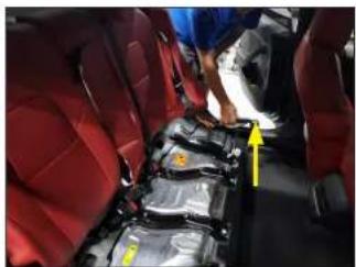
Interior view of a red car seat with a person's seatbelt and yellow arrow indicating direction (no text or symbols visible)STEP 3
Lift the rear seat bottom cushion at the front edge corners on both the driver and passenger sides. This will expose the release latch underneath each side.
Once exposed, pull each latch towards the center of the vehicle to release the rear seat bottom cushion. Once unlatched, lift and remove the rear seat bottom cushion from the vehicle.
natural_image
Interior view of a car showing red seats and black leather seats with yellow arrows pointing to specific components (no visible text or symbols)STEP 4
Carefully lift the rear door sill trim panel on each side of the vehicle to release each panel from the mounting clips. Remove the rear door sill panels from the vehicle.
Page 4 • JL Audio, Inc., 2023 Continued on Next Page
SB-TE-3G1-10TW1 INSTR_SKU#011578
natural_image
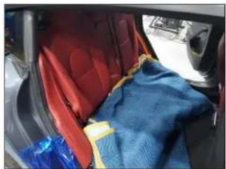
Interior view of a car showing a blue medical device attached to the backrest, with red seats and a yellow safety harness visible (no text or symbols)STEP 5
Place a blanket over the exposed surfaces under the rear seat bottom, then fold the rear seat backs down.
natural_image
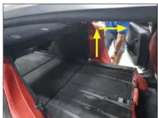
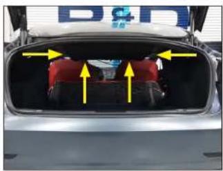
Interior view of a car showing rear seats and a vehicle interior with yellow arrows indicating movement or flow (no visible text or symbols)STEP 6
Pull the side bolster cushion out at the top to release the clip, then lift the side bolster cushion up to remove.
Repeat on the passenger side.
natural_image
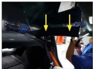
Interior view of a car with yellow arrows pointing to a structural component (no visible text or symbols)STEP 7
Carefully unclip and remove the top pillar panel on the driver side. The panel is held in place with clips. It is also secured from the backside with a safety bungee, which will need to be unclipped before removing the panel.
Repeat on the passenger side.
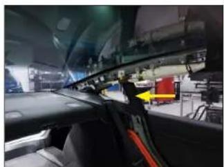
natural_image
Interior view of a car cockpit with visible wiring and a yellow arrow pointing to a component (no text or symbols)STEP 8
Carefully unclip and remove the indicated pillar panel on the driver side.
Repeat on the passenger side.
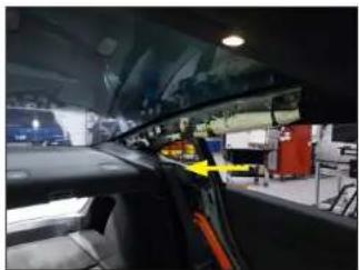
natural_image
Interior view of a car showing the hood and side panel, with no visible text or symbols.STEP 9
Carefully pull the driver side seat belt retainer panel forward to release the mounting hooks and remove.
Repeat on the passenger side.
natural_image
Close-up of a car's front bumper with yellow arrows pointing to specific areas (no text or symbols visible)STEP 10
Remove the two indicated round panel clips from the front edge of the parcel shelf panel.

natural_image
Close-up of a hand adjusting a car engine component with yellow arrows pointing to the valve (no visible text or symbols)STE P 11
Carefully lift up on the front of the parcel shelf panel at each end to expose the latching mechanism underneath. Release the latch on each end of the parcel shelf panel.
Leave the parcel shelf panel in place for now.
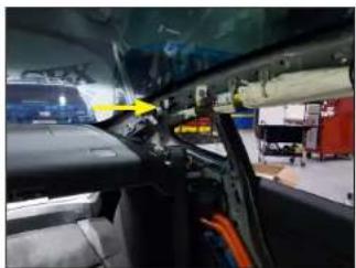
natural_image
Interior view of a car cockpit with visible dashboard, steering wheel, and industrial equipment (no text or symbols)STEP 12
Disconnect the indicated harness on the driver side.
Page 5 • J. Audio, Inc., 2023 Continued on Next Page
SB-TE-3G1-10TW1 INSTR_SKU# 011578

natural_image
Interior view of a car showing internal components and wiring (no visible text or symbols)STEP 13
Disconnect the two indicated harnesses on the passenger side. The parcel shelf panel should now be free to remove from the vehicle.

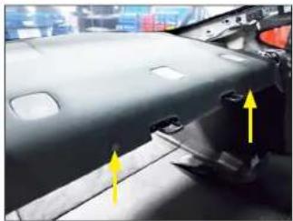
natural_image
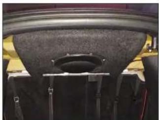
Top-down view of a car head panel with visible structural components and mounting holes (no text or symbols)STEP 14
Carefully place the parcel shelf panel face down onto a flat surface. Cut and remove the foam padding material from the panel in the indicated area.
Note: The foam material has already been removed in this image. Do not cut through the top side of the parcel shelf panel.

natural_image
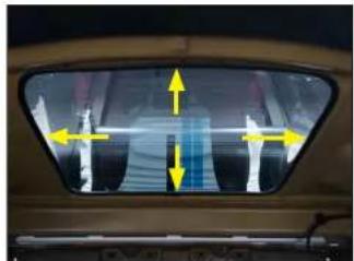
Close-up of a white ventilation grille with yellow decorative border (no text or symbols visible)STEP 15
Use a pencil or marker to mark the cutout opening on the underside of the parcel shelf as indicated.
Once marked, carefully cut the opening.
natural_image
Interior view of a train car with yellow directional arrows indicating movement or flow (no text or symbols visible)STEP 16
After cutting the opening in the parcel shelf, wear protective gloves and attach the supplied 52" Rubber Edge Trim to the perimeter of the cutout.

natural_image
Interior view of a car showing a person seated in the back seat with yellow arrows pointing to the dashboard (no visible text or symbols)STEP 17
Referring to Page 2 as a guide, create four screw assemblies by sliding a supplied 1/4" Black-Oxide Split Lock Washer and 1/4" Black-Oxide Flat Washer over a 1/4"-20 1-1/4" Black-Oxide Button Head Hex Drive Screw. Use the four assemblies to attach the supplied left and right Lower Brackets to the sides of the enclosure. Carefully, place the top of the enclosure through the parcel shelf opening.
natural_image
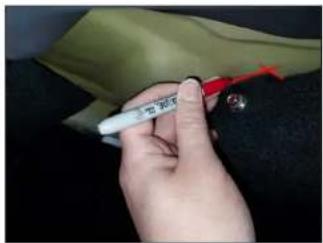
Close-up of a hand holding a white pen and red tool, partially covered by a beige fabric (no visible text or symbols)STEP 18
With the enclosure lifted into place, position it against the rear edge of the parcel shelf mounting hole (towards the rear of the vehicle) and hold it in place.
Use a pencil or a marker to mark the position of the side and rear edges of the left (shown) and right Lower Brackets onto the underside of the parcel shelf surface as indicated.
natural_image
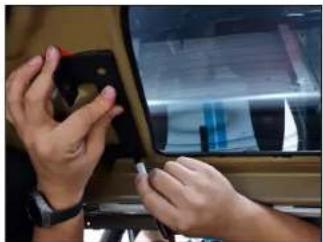
Close-up of hands installing or adjusting a small electronic device on a car's front panel (no visible text or symbols)STEP 19
Carefully lower the Stealthbox from the opening and remove both left and right Lower Brackets from the enclosure.
Align the left Lower Bracket to the marks made in STEP 18. Use a marker to mark the two mounting holes in the left Lower Bracket to the underside of the parcel shelf.

natural_image
Close-up of hands installing or adjusting a mechanical component on a vehicle (no visible text or symbols)STEP 20
Align the right Lower Bracket to the marks made in STEP 18. Use a marker to mark the two mounting holes in the right Lower Bracket to the underside of the parcel shelf.
Page 6 • J. Audio, Inc., 2023 Continued on Next Page
SB-TE-3G1-10TW1 INSTR_SKU# 011578
natural_image
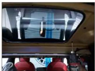
Interior view of a vehicle showing a large overhead display with white text and red seats, no visible text or symbols.STEP 21
Use a 1/8" bit to to drill a starter hole in the four bracket hole marks made in STEP 19 and STEP 20.

natural_image
Interior view of a car showing the windshield and seat area, with no visible text or symbols.STEP 22
Use a 1/4" bit to enlarge the four starter holes drilled in STEP 21.

natural_image
Close-up of a car body panel with two yellow arrows pointing to the front and side (no text or symbols visible)STEP 23
From inside the vehicle, place one supplied Upper Bracket on the left and one supplied Upper Bracket on the right of the parcel shelf hole as shown. Align the mounting holes of the two Upper Brackets with the holes drilled in STEP 22.

natural_image
Interior view of a car showing a rearview dashboard and side-mounted sensors (no text or symbols visible)STEP 24
Referring to Page 2 as a guide, pass two 1/4"-20 7/8" Black-Oxide Flanged Button Head Screws through the mounting holes in each Bottom Bracket, through the rear parcel shelf, and through the Upper Brackets inside the vehicle cabin. From inside the vehicle, use two 1/4" Flat Washers, two 1/4" Split Lock Washers, and two 1/4"-20 Hex Nuts per Upper Bracket to fully attach the bracket assemblies to the vehicle.
natural_image
Top-down view of a car trunk with yellow arrows pointing to internal components (no visible text or symbols)STEP 25
Route the speaker cable and connect to it to the enclosure's terminal cup. Carefully place the enclosure into the parcel shelf opening. Align each of the Lower Bracket mounting holes with the threaded inserts on each side of the enclosure.
Referring to Page 2 as a guide, use the four screw assemblies created in STEP 17 to fully attach the enclosure to each Lower Bracket.
natural_image
Close-up of a car's front wheel and side-mounted sensors (no visible text or symbols)STEP 26
Close the rear seat back. Reinstall the factory panels and rear seat bottom cushion.
SB-TE-3G1-10TW1 INSTR_SKU#011578
CONGRATULATIONS!
You have completed the installation for this model! Enjoy your new Stealthbox®!

natural_image
Top-down view of a silver car trunk with illuminated rear seats and side lights (no text or symbols visible)MID/HIGH FREQUENCY DRIVER FITMENT
A variety of JL Audio coaxial and component systems will fit in the factory speaker locations of your vehicle.
| Location / OEMSpeaker Size | Suggested JL Audio Speaker Models | |
| Coaxial Models Component Models | ||
| Front Doors /8.0 inch | C1-650 x^(1) , C2-650 x^(1) | C1-650 ^(1) , C2-650 ^(1) , C3-650 ^(1) ,C7-650 cm^(1,2) |
| Rear /4.0-inch | C1-400 x^(1) , C2-400 x^(1) | C7-350 cm^(1,2) |
1 - Installation may require adaptor, 2 - Component woofer only
JLAUDIO. How we play.\*
text_image
(954) 443-1100 www.jlsudio.com All social classes are unique to change without notice. It is/are "and how my play" as regularly relevantly. It is/are "the Com" and is popular here to understand the content. http://www.ijlsudio.com - 2023.16/jlss.com - for more detailed information please call us at www.jlsudio.com.JLA-SKU# 011578 • ver. 03.29.23 • 10369 NORTH COMM-RC-PARKWAY • MIRAMAR, FLORIDA • 33025 • USA
