KRH4801U - Range hood Kucht - Free user manual and instructions
Find the device manual for free KRH4801U Kucht in PDF.

| Brand | Kucht |
| Model | KRH4801U |
| Product Type | Range Hood |
| Power Requirements | 110V-120V / 60Hz |
| Installation Height (bottom of hood to cooktop) | 27" - 30" |
| Duct Diameter | 7" round (vertical) |
| Number of Fan Speeds | 4 speeds (quiet, low, medium, high) |
| Control Type | Sensor buttons with remote control |
| Lighting | 2 x LED bulbs (12V/1.5W) |
| Filter Type | Stainless steel baffle filters (2 pieces) |
| Grease Filter Cleaning | Dishwasher safe; clean monthly with warm water and detergent |
| Timer Delay Function | Yes, up to 15 minutes adjustable |
| Remote Control Included | Yes |
| Material | Stainless steel |
| Usage | Residential indoor use only |
| Safety Certifications | Complies with ANSI/NFPA 70 and CSA C22.1 |
| Amperage | Not specified in manual; typical range hoods use ~5A |
| Weight | Not specified; estimate 40-60 lbs based on similar models |
| Dimensions (W x D x H) | Not specified; model KRH4801U likely 48" width, typical depth 20-22", height variable |
Frequently Asked Questions - KRH4801U Kucht
User questions about KRH4801U Kucht
0 question about this device. Answer the ones you know or ask your own.
Ask a new question about this device
Download the instructions for your Range hood in PDF format for free! Find your manual KRH4801U - Kucht and take your electronic device back in hand. On this page are published all the documents necessary for the use of your device. KRH4801U by Kucht.
USER MANUAL KRH4801U Kucht
INSTALLATION GUIDE AND USER MANUAL
APPLICABLE MODEL: KRH3001U, KRH3601U, KRH4801U, KRH3002U, KRH3602U, KRH4802U, KRH3003U, KRH3603U, KRH3004U, KRH3604U
Safety Notice
Approved for residential type untis for residential use only read these indtructions and be safe.
Please read these instructions completely before starting.
The installation of the appliance must respect all codes.
Important: Save these instructiond so that you can provide the electrical inspector in your area.
Safety Warning: Turn off the circuit in the electrical panel and lock front panel to connect the cord of this unit.
Power requirement: 110V-120V/60HZ
CAUTION: USE THIS PRODUCT FOR GENERAL FAN ONLY. DO NOT USE THIS PRODUCT TO EXHAUST FUMES OR HAZARDOUS OR EXPLOSIVE MATERIALS.
WARNING TO REDUCE THE RISK OF FIRE, ELECTRICAL SHOCK OR INJURY TO PEOPLE, OBSERVE THE FOLLOWING:
- Use this unit only for the purposes intended by the manufacturer. If you have any questions about this product, contact the manufacturer.
- Before the machine's maintenance or cleaning, turn off the electrical panel and lock the panel blocking feature to prevent from accidentally activating the power. If it is not possible to lock the access panel, attach a highly visible label to the electrical panel.
- A qualified person should perform the installation and wiring of the electricity in accordance with all codes and all standards, including fire resistance rating.
- When you use hood together with stove, please do not close the window and door of the kitchen. Because during the fuel stove working, which will consume lots of air, so do open the door and window to make the kitchen ventilating, to avoid any suffocation.
- It is important to provide sufficient air for proper combustion of heating equipment and proper evacuation of gases through the chimney pipe to prevent back flow of air. Follow the instructions and safety standards of the manufacturers of heating equipment, such as those published by the National Fire Protection Association(NFPA),the American Society for Heating, Refrigeration and Air Conditioning Engineers(ASJRAE) and the code authorities in your area.
- When cutting or drilling into wall or ceiling, be sure not to damage electrical wiring or other access to public service.
- Always evacuate outside the conduit system.
To reduce the risk of fire and to properly exhause air, be sure that the pipe is leading outside, do not exhause air into the space between the walls, ceilings, attics, crawl spaces or garages.
Warning: TO REDUCE THE RISK OF FIRE, USE ONLY METAL DUCT. Install this hood in accordance with all the requirements mentioned.
WARNING: TO REDUCE THE RISK OF FIRE, GREASE THE RANGE.
- Never leave the stove unattended when it is at a high temperature. Boil overs cause smoke and fat that overflows can ignite. Heat the oil slowly at a low or medium temperature.
- Always operate the hood when you use the stove to high heat or when you Flame.
- Clean ventilating fans frequently. Do not let fat accumulate on the filters or propellers.
- Use proper pan size. Always use a pot size appropriate to the stove element.
- Do not touch on-workig or off-soon bulb, to avoid any thorny.
Warning
TO AVOID INJURING SOMEONE IN A GREASE FIRE, FOLLOW THE FOLLOWING:
- SMOTHER FLAMES with a lid to the dimensions of the cooking hobs, a cookie sheet or other metal tray, then turn off the gas or power supply of the stove. BE CAREFUL NOT TO BURN YOURSELF. If the flames do not go out immediately, LEAVE AND CALL THE FIRE DEPARTMENT.
- NEVER PICK IP A FLAMMING PAN, you could hurt yourself.
- DO NOT USE WATER, including Dish towels or wet towels-a violent steam explosion of dew may occur.
- Use an extinguisher only if:
. You are sure to have a Class ABC extinguisher that you know how to use.
. The fire is small and confined to the area where it was formed.
.Firefighters were called.
.You can fight against the fire with an exit behind you.
Operative Mode
Always leave safety grills and filers in place. Without the presence of thesem blowers could catch hair, fingers or clothing. The manufacturer is not liable if detailed in this manual for installation info, maintenance and proper use of the product are not observed. The manufacturer declines all responsibility for any injury caused by negligence. This product is manufactured for internal use. Do not use this appliance outdoors.
Electrical requirements and installation requirements
Power Requirements
IMPORTANT
Observe all governing codes and ordinances. The customer is responsible for: Contacting an electrician-installer. Check that the electrical installation is adequate and in conformance with the National Electrical Code, ANSI / NFPA 70 (latest edition *) or CSA Standards C22.1-94, Canadian Electrical Code, Part 1 and C22.2 No.0-M91 (the latest edition **) of the CSA, and all codes and ordinances in your area. If codes permit and use a wire to separate the ground, it is recommended to check the path of the wire by an electrician. Do not put the device to land on a gas line. Consult a qualified person if you are not sure that the hood is properly grounded electrically. Do not install a fuse in the neutral circuit or circuit ground.
Location of the electrical installation
- The cable must enter the rear wall at least 20 to 1/4 "above the height of the installation base, and between 7-5/8" and 4-7/8 "from the left side of the midline.
IMPORTANT
Keep these instructions in order to return them to the electrical inspector. The hood must be plugged directly into a 110 volt wall outlet.
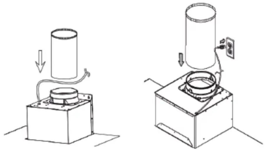
natural_image
Two technical line drawings showing a cylindrical device being compressed and then placed on a base, with no visible text or symbols.Before installing the hood
-
To ensure the most efficient ventilation possible, install the pipe in a straight line or with the least elbows possible. CAUTION: The output of the vent pipe should give to the outside.
-
Two people are required for installation.
-
Supplied hardware can secure the hood to most walls and ceilings, consult a qualified installer to ensure that the hardware provided is suitable for your type of wall or cabinet.
-
In the case of areas prone to COLD WEATHER, install a check against extra-circulation to minimize the cold air return and a nonmetallic thermal break to minimize conduction of outside temperature in the duct. The valve must be placed on the side of the cold air from the heat insulator. The insulation must be placed as close as possible to where the pipe enters the heated part of the house.
-
Air booster: The building code in your area may require the use of a make-up air system if you use a ventilation system which leads the movement of air exceeding a certain number of CFM. The number of ft3/min varies from one region to another. Consult your HVAC professional for specific requirements in your area.
Remove the packaging.
CAUTION
Carefully remove the cardboard, gloves to protect against sharp edges.
Examples and positioning possibilities ducts
Follow the letter of the guidelines presented in this manual.
The manufacturer declines any liability with respect to any loss, damage or fire caused by non-observance of the instructions contained in this manual.
Ventilation methods
The hood is equipped with a vertical transition to remove fumes outside.
Recommended diameter conduit model and wall chimney hood and hood island: vertical round pipe 7" tolerance + or - 1.
Models Chimney hood Wall: KRH3003U, KRH3004U
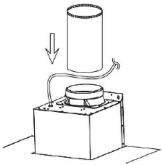
natural_image
Simple line drawing of a cylindrical object being heated by a tube, with an arrow indicating downward motion (no text or symbols)
natural_image
Technical line drawing of a mechanical support structure with no visible text or symbols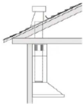
natural_image
Technical line drawing of a structural support frame with diagonal roof and vertical supports (no text or symbols)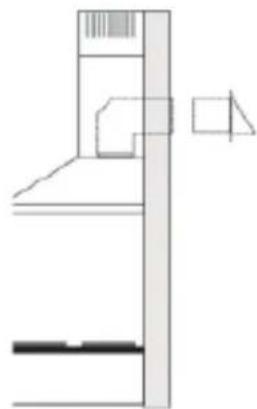
natural_image
Pure technical line drawing of a mechanical assembly without any text, numbers, or symbols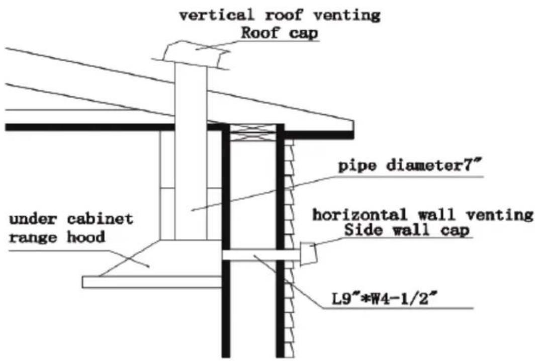
Do not cut a joist or stud unless it is absolutely necessary to do so. If you need to cut a joist or stud, you must build a support framework. Supplied hardware can secure the hood to most walls and ceilings. However, you should ask a qualified technician to check the strength of materials depending on the type of wall or ceiling. Before cutting, make sure there is enough clearance in the ceiling or wall for the outlet pass. You can determine for yourself how high you install the hood above the stove. Over the hood near the stove, it is more effective to capture cooking odours, grease and smoke.
ClearanceTraining
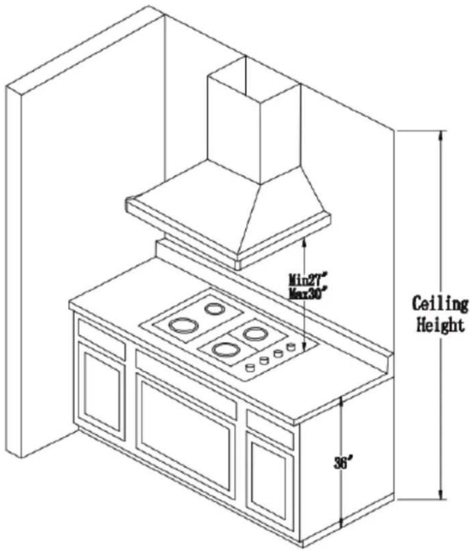
Caution:
When install the hood, the height should not be too high or too low. Before the installation, please inspect the maximum height of your ceiling and bonnet. Too high, will affect the efficiency of the hood; too low, stove temperature will damage some parts of the hood. So the installation height requirement is: the distance between the bottom of the hood to the surface of the cooktop is Max 30"/ Min 27"(as figure showing)
Installation
If possible, unplug the stove and move it in order to have better access to the rear wall. Otherwise, place a thick blanket on the counter and the cooking surface to protect it from damage and dirt. Select a flat surface for assembling the device.
Then put the debris of the cover and hardware on to the protective cap.
Determine and mark the center line on the wall where you installed the canopy hood.
Determine a comfortable height for the user and mark it on the wall behind the stove top.
Place the template on the center line and the bottom of the hood with adhesive tape.
Place the squares of the flue
The flue must be installed against the back wall and the ceiling.
This bracket will keep the chimney up to the top.
Attach the brackets to the wall:
- Align the center lines drawn on the bracket with the center lines on the wall.
- Identify the two screw holes on the wall.
- Drill pilot holes 5/16 "in the locations shown.
- Place the fastening clips to the wall.
- Tighten wood screws, by hand, in the attachments to allow hooks to expand. Remove the screws.
- Drill guide hole, € 5/16inch.
- Make clamp fix to the wall, screw down the bolts on the wall.
- Attach the bracket to the wall using the screws and / or fasteners.
Ceiling pipe
If the duct vents just above the ceiling:
- Use a level to draw a line, the center line of the template to the ceiling.
- Measure at least 4 "from the back wall to the center of the circle with a hole 7 - 12 " in the ceiling.
Lead in the wall If the duct vents at the rear:
Note: For a minimum extension of the chimney, we recommend using an adapter circular / rectangular fireplace.
- Use a level to draw a straight line from the center line on the template.
- Measure at least 26 - 1/4 "(the measure may vary elbow used) above the pencil line indicating the height of the bottom of the system, the circle of a conduit hole 7 - 12 " in diameter (the hole may be enlarged for the passage of the elbow).
Necessary Tools


natural_image
Technical line drawing of a three-tiered industrial chimney or chimney structure (no text or symbols)KRH3003U
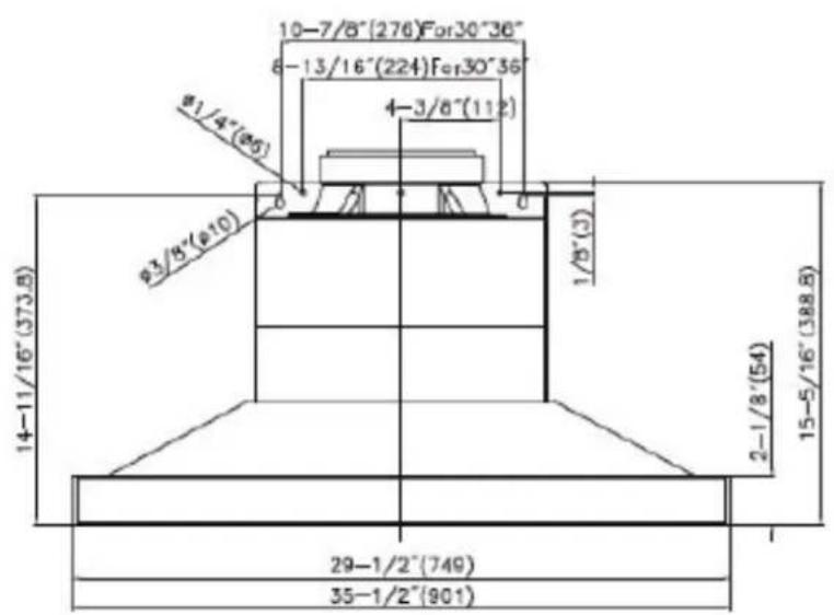
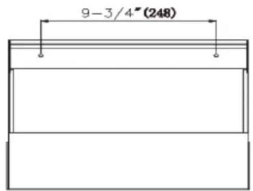
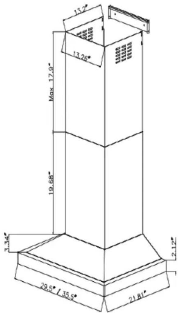
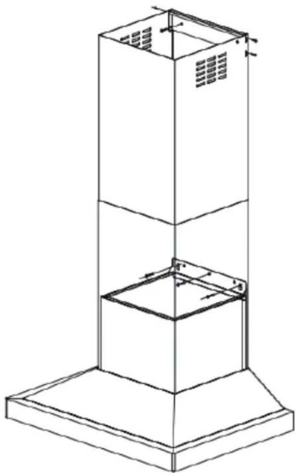
Installation dimension figure of KRH3004U as below:

natural_image
Isometric line drawing of a tall cylindrical structure with a base platform and internal components, no text or symbols present.KRH3004U
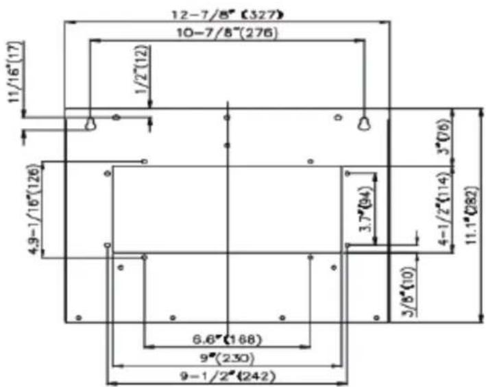
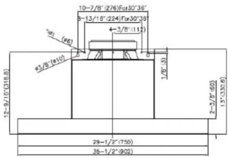
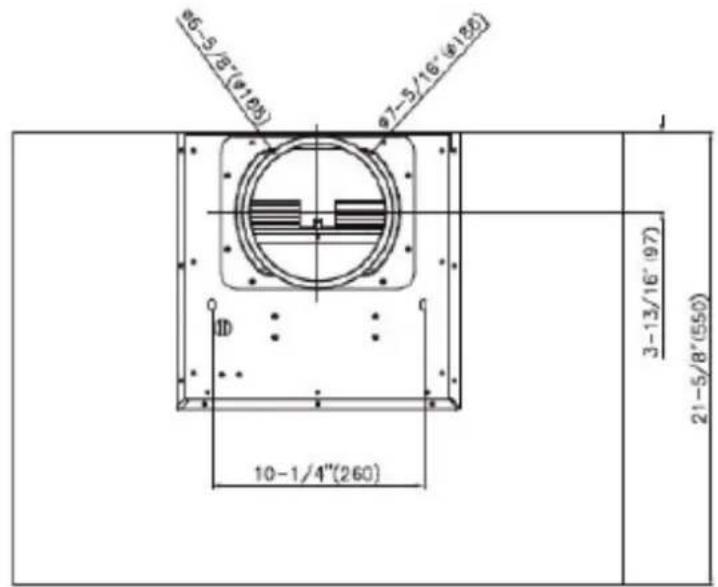
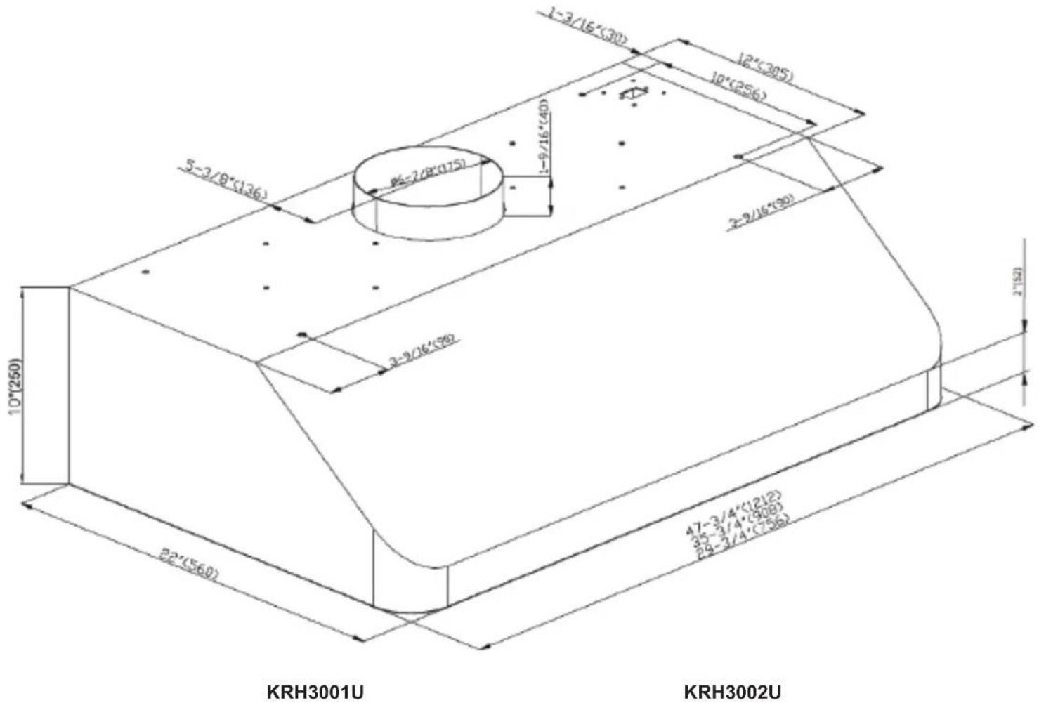
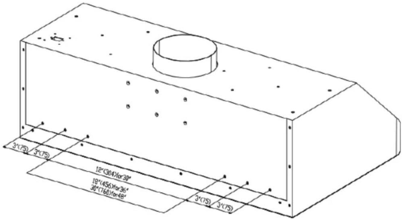
Installation dimension figure of KRH3001U and KRH3002U as below:
Fix 6pcs screws( see figure 4) to the installation dead plate
Fix the installation dead plate to the wall by screws( see figure 5)
Use double-faced aluminum foil sealed-joint( see figure 6)
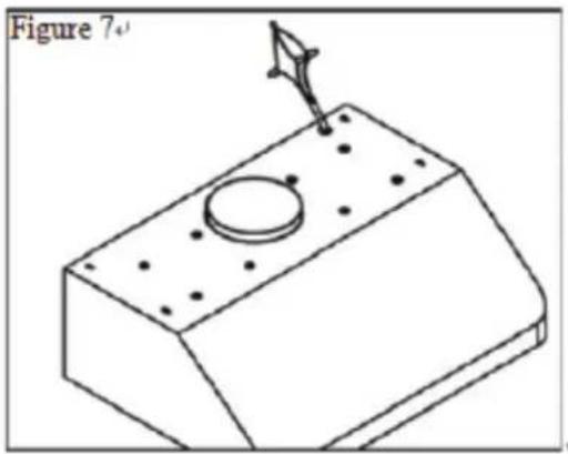
Power line color (black to black, white to white, green to green) (see figure 7)
Oil box of the hood (see figure 8)
Installation of clapboard filter screen (see figure 9)

natural_image
Technical line drawing of a mechanical assembly with two components and bolt holes (no text or symbols)Figure4

natural_image
Isometric line drawing of a cylindrical object on a surface with two wall-mounted sensors (no text or symbols)Figure5

natural_image
3D technical illustration of a mechanical component with a threaded rod inserted into a base (no text or symbols)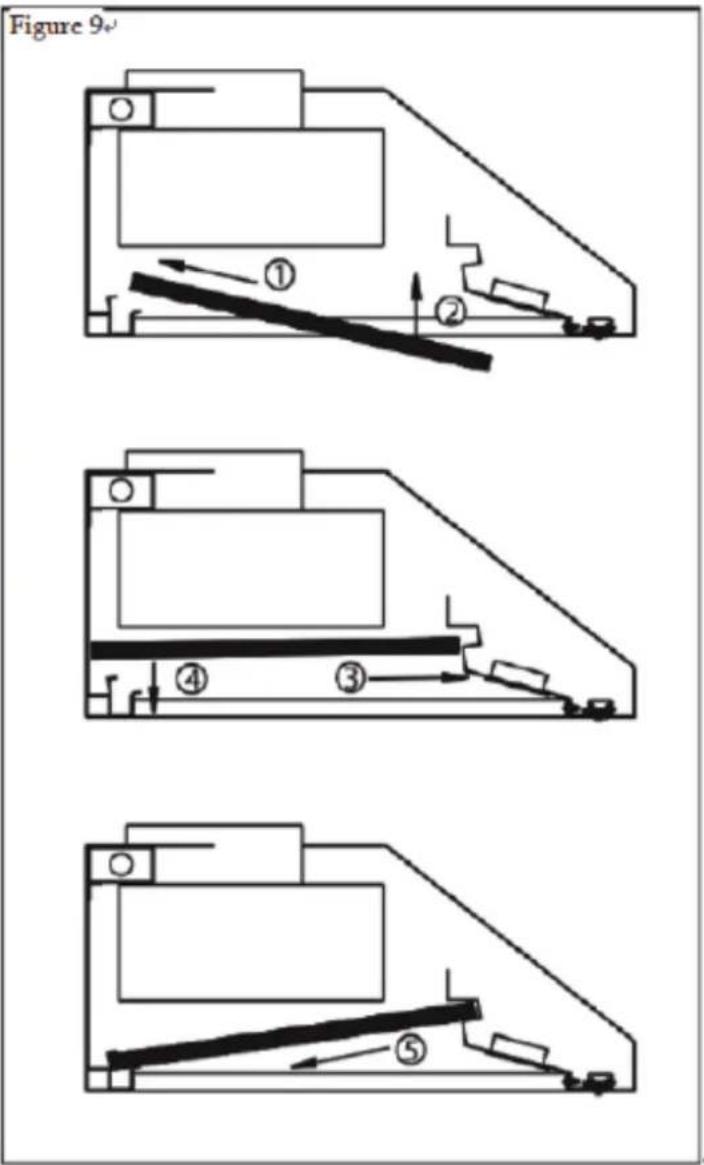
natural_image
3D diagram of a mechanical component with a central circular feature and an arrow pointer (no text or symbols)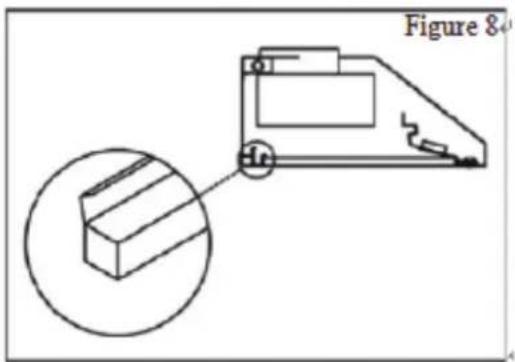
Description orders for model KRH3001U KRH3003U KRH3004U

Automatic activation control function of the sensor:
There are 5 pcs sensor buttons,1pc remote control signal lamp(remote controller included), 2 pcs stainless steel grease boxes,2 pcs stainless steel baffle filters and 2 pcs led bulbs( 12V/1.5W).
A0 button: Remote control signal lamp
A1 button: Power( on/off)
A2 button: LED bulb
A3 button: Display screen
A4 button: Time Delay. A5 button: Low speed
A6 button: High speed
A4 button equip with Max 15 minutes after power off, A1 button( on/off) control to directly started or off.
Open The Fan
Keep your hood working during the cooking, and keep vantilating.
Press A1 button, then A3 display screen open.
Button A5 and A6 activates, high speed (F4), average speed(F3), low speed(F2), quiet speed(F1).
Control Panel Layout and Button Disposition

Close The Fan
Off time-delay function just could close the fan, not affected the lamplight setting.
15 minutes time-delay
When fan working, press A4 button, digital screen will blink several seconds, default setting is 1 minute, after that, will shut off automatically.
During fan working, if you need to adjust time-delay function, press A4 button one time, will blink for a few seconds, press A6 button to increase delay-time, set the figure timers as the time you want, max delay-time is 15 minutes.
If time-setting changes from A6 button to A5 button, during the process, speed changes, but does not affect count down.
Off immediately
Press A1 button two times, fan turn off immediately.
Bulb control
Press A2 button once, turn on the lights, and again to turn off.
Press A2 button or A4 button, then will not able to turn on LED light.
Warning: In case of any scald, do not touch LED light, unless hood is closed or cooled.
A0 button: same as above.
Remotesensor: A0 is the remote control. Remote sensor to receive infrared (IR) remote control signal.
KRH3002U operating instruction as following:
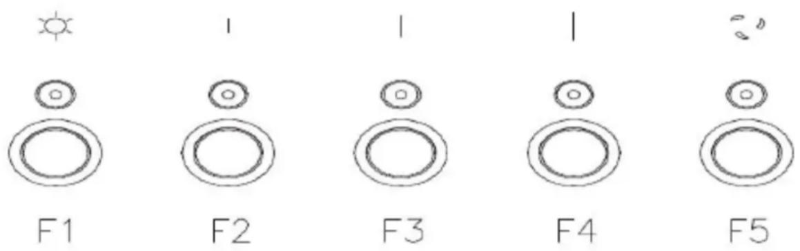
Function Button: LED light button F1 low speed F2 medium speed F3 high speed F4 time-delay/on-off F5
Light Button: Power on, press F1 button once, turn on the lights, and again to turn off.
Fan button: When need to open the hood, turn on the power, press F2 button (low speed) F3 button(medium speed)
F4 button(high speed)
Time-delay Button: Power on, press any button of F2/F3/F4, fan starts and F5 light automatically but does not blink.
Press F5 again, time-delay function starts, when F5 indicator light starts to blink, time-delay function unadjustable,
default setting time is 5 minutes. Press F5 button again, time-delay and fan both close, LED light still on, which is independent switch.
MAINTENANCE
WARNING
Before servicing or cleaning unit, switch power off at service panel and lock in access to prevent it being switched on accidentally. If the power panel can not be locked, put a prominent warning device, such as a brightly coloured label.
Grease filters
The grease filters should be cleaned once a month or as needed. To remove grease filter, pull the metal latch down. This will disengage the filter hood. Tilt the filter down, then remove. To clean the filters, use a solution of warm water and detergent. Let them dry, then reinstall. The metal filters are dishwasher-safe. Clean filters made entirely of metal in the dishwasher using a non-phosphate detergent. Using a detergent containing phosphates and local water conditions may cause discoloration of the filters, without affecting their performance. This discoloration is not covered under warranty.

natural_image
Isometric view of a rectangular grid structure with parallel lines and small protrusions (no text or symbols)Hood Cleaning
Cleaning stainless steel: how to keep his "lustrous appearance" and help prevent corrosion.
What to do:
- Wash surfaces regularly with a cloth or a clean cloth soaked in warm water and mild soap or dish detergent.
- Always clean in the direction of squall lines (direction of the grain).
- Always rinse well with clear water (2 or 3 times) after cleaning and dry completely.
- A household cleaner designed for stainless steel can also be used.
Don'ts:
- Use steel wool or stainless steel or any other scrapers to remove stubborn dirt.
- Use any harsh or abrasive cleansers.
- Allow dirt to accumulate.
- Allow the plaster dust or any other construction residues reach the hood. Cover the hood while working to ensure no dust hood.
To avoid when choosing a detergent
- Any cleaners that contain bleach, because they attack stainless steel.
- Any product containing chloride, fluoride, iodide, bromide, they quickly deteriorate surfaces.
- Any combustible products used for cleaning such as acetone, alcohol, ether, benzene, etc. These products are highly explosive and should never be used near a stove.
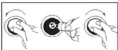
To replace the bulbs:
- Shut off the power
- Take off the grease filters, press both sides of the elastic clamps on the bulb, make which loose.
3.Gently push outward, take out the bulbs.
P.S: If necessary, wear gloves when taking out the bulbs.
natural_image
Three-step illustration of a human ear with hand gestures, showing head, torso, and ear (no text or symbols)

WE TRANSFORM A SIMPLE KITCHEN INTO A PRO ONE. THIS IS WHY WE CARE ABOUT MAKING VERY HIGH PERFORMANCE RANGES AND HOODS, TO MAKE YOU FEEL LIKE A PRO AND STYLISH COOKER.
DESIGN: LONDON DC - WWW.LONDON-DC.COM

- INSTALLATION GUIDE AND USER MANUAL
- Safety Notice
- WARNING: TO REDUCE THE RISK OF FIRE, GREASE THE RANGE.
- Warning
- Operative Mode
- Electrical requirements and installation requirements
- Power Requirements
- IMPORTANT
- Before installing the hood
- Examples and positioning possibilities ducts
- Caution:
- Installation
- Ceiling pipe
- Description orders for model KRH3001U KRH3003U KRH3004U
- Automatic activation control function of the sensor:
- Open The Fan
- Control Panel Layout and Button Disposition
- Close The Fan
- minutes time-delay
- Off immediately
- Bulb control
- MAINTENANCE
- Grease filters
- Hood Cleaning
- What to do:
- Don'ts:
- To avoid when choosing a detergent
- To replace the bulbs:
Brand : Kucht
Model : KRH4801U
Category : Range hood