
EW5000 - Heating Escea - Free user manual and instructions
Find the device manual for free EW5000 Escea in PDF.

| Product Type | Outdoor Wood Burning Cooking Fireplace |
| Brand | Escea |
| Model | EW5000 |
| Dimensions (Without Fascia) | 996mm (W) x 758mm (H) x 548mm (D) |
| Dimensions (With Fascia) | 1292mm (W) x 758mm (H) x 551mm (D) |
| Weight (Without Fascia) | 90.3 kg |
| Weight (With Fascia) | 99.8 kg |
| Fuel Type | Wood and Charcoal |
| Installation Options | Concrete/Masonry Cavity, Timber/Combustible Cavity with AAC Heat Cell, Kitset Enclosure |
| Flue System | EW Concrete Cavity Flue Kit (concrete install) or EW5000 Timber Cavity Flue Kit (timber install) |
| Cooking Surface | Removable cooking surface with three height positions; must be seasoned before use |
| Materials | Steel firebox, stainless steel fascia (optional), high-temperature paint |
| Safety Features | Ash pan, rear heat deflector, grate; requires non-combustible clearances |
| Minimum Cavity Size (Concrete) | 1000mm (W) x 490mm (D) x 760mm (H) |
| Minimum Cavity Size (Timber) | 1270mm (W) x 1550mm (H) x 770mm (D) |
| Clearance to Combustibles (Front) | 2000mm minimum from fire opening |
| Clearance to Combustibles (Sides) | 650mm minimum |
| Venting Required (Concrete) | Total open area ≥ 28,600 mm², no higher than 300mm from base |
| Venting Required (Timber) | Total open area ≥ 94,600 mm², no higher than 300mm from base |
| Warranty (Basic Firebox) | 5 years parts and labour |
| Warranty (Removable Parts) | 2 years parts and labour |
Frequently Asked Questions - EW5000 Escea
User questions about EW5000 Escea
0 question about this device. Answer the ones you know or ask your own.
Ask a new question about this device
Download the instructions for your Heating in PDF format for free! Find your manual EW5000 - Escea and take your electronic device back in hand. On this page are published all the documents necessary for the use of your device. EW5000 by Escea.
USER MANUAL EW5000 Escea
ESCEA FIREPLACE KITCHEN
Installation Instructions and User Guide
Please contact Escea if you require warranty work. Warranty repair work must be carried out by a recognised Escea woodfire installer. It is recommended that recognised Escea Wood Fire Installers are also used to carry out annual servicing requirements (particularly during the warranty period). For contact details of recognised Escea Wood Fire Technicians in your area, or for replacement parts, please contact the retailer from whom the appliance was purchased from, or visit our website.
All installation work must comply to AS/NZS 2918 Domestic solid fuel burning appliances- Installation AND these installation instructions. Any work undertaken that does not comply to AS/NZS 2918 AND these installation instructions will not qualify for the Escea warranty. Escea will not be accountable for any unsafe installation that does not comply to AS/NZS 2918.
Please contact your local council for updates to AS/NZS 2918 or additional restrictions. The installation must comply to any additional requirements to qualify for the Escea Warranty.
Manufactured by: Escea Ltd, PO Box 5277 Dunedin NZ, Ph: +64 3 478 8220
For contact details of your local Escea distributor or dealer, please visit www.escea.com,
call 0800 173 000, or email us at info@escea.com.
From Australia, please visit www.escea.com.au, call AU: 1800 460 832 or WA: 1800 730 140, or email us at info@escea.com
A Saftey Information 4
B Product Details 6
B1 Product Description
B2 Installation Scenarios
B3 Product Dimensions
C External Clearances to Combustible Surfaces 10
D Concrete/ Block Structure Installation 11
D1 Minimum Requirements of Concrete/ Block Structure
D2 Sealing Requirements
D3 Concrete/ Block Structure Flue System Installation
E Timber/ Combustible Structure Installation 15
E1 Minimum Requirements of the Timber/ Combustible Structure
E2 Sealing Requirement
E3 Autoclaved Aerated Concrete (AAC) Heat Cell Assembly
E4 Timber/ Combustible Structure Flue System Installation
E5 Heat Cell Construction Recommendations
F Assembling and Installing the Fireplace 22
F1 Placement of Interior Parts
F2 Fitting the Fascia
G Operation Guide 24
G1 Fuel Selection
G2 Starting the Fire
G3 Loading the Fire
G4 Extinguishing the Fire
H Maintenance 26
H1 Cleaning the Fascia
H2 Chimney Maintenance
H3 Recommended Refurbishment Products
I General Warranty Terms and Conditions 27
NOTICE
DO NOT DISCARD THIS MANUAL
IMPORTANT OPERATING AND MAINTENANCE INSTRUCTIONS INCLUDED.
READ, UNDERSTAND AND FOLLOW THESE INSTRUCTIONS FOR SAFE INSTALLATION AND OPERATION.
LEAVE THIS MANUAL WITH PARTY RESPONSIBLE FOR USE AND OPERATION.
WARNING
IF THE INFORMATION IN THESE INSTRUCTIONS IS NOT FOLLOWED EXACTLY, A FIRE OR EXPLOSION MAY RESULT CAUSING PROPERTY DAMAGE, PERSONAL INJURY OR DEATH.
IMPROPER INSTALLATION, ADJUSTMENT, AERATION, SERVICE OR MAINTENANCE CAN CAUSE INJURY OR PROPERTY DAMAGE, BODILY INJURY OR EVEN DEATH. PLEASE READ ENTIRE MANUAL BEFORE YOU INSTALL AND USE YOUR APPLIANCE.
THIS APPLIANCE IS NOT TO BE USED BY PERSONS (INCLUDING CHILDREN) WITH REDUCED PHYSICAL, SENSORY, OR MENTAL CAPABILITIES, OR LACK OF EXPERIENCE AND KNOWLEDGE, UNLESS THEY HAVE BEEN GIVEN SUPERVISION OR INSTRUCTION CONCERNING USE OF THE APPLIANCE BY A PERSON RESPONSIBLE FOR THEIR SAFETY.
WARNING: THIS APPLIANCE AND FLUE SYSTEM MUST BE INSTALLED IN ACCORDANCE WITH AS/NZS 2918 AND THE APPROPRIATE REQUIREMENTS OF ANY RELEVANT LOCAL/NATIONAL BUILDING CODES.
CAUTION: THIS APPLIANCE SHOULD BE MAINTAINED AND OPERATED AT ALL TIMES IN ACCORDANCE WITH THESE INSTRUCTIONS:
- The appliance should be allowed to cool before servicing.
- Do not operate without fully assembling all components.
- Risk of cuts and abrasions. Wear protective gloves and safety glasses during installation. Sheet metal edges may be sharp.
- Do not operate appliance before reading and understanding operating instructions. Failure to operate appliance according to operating instructions could cause fire or injury.
CAUTION: MIXING OF APPLIANCE OR FLUE SYSTEM COMPONENTS FROM DIFFERENT SOURCES OR MODIFYING THE DIMENSIONAL SPECIFICATION OF COMPONENTS MAY RESULT IN HAZARDOUS CONDITIONS. WHERE SUCH ACTION IS CONSIDERED, THE DISTRIBUTOR: ESCEA LTD SHOULD BE CONSULTED AT THE FIRST INSTANCE.
- This appliance can be very hot when burning.
- Combustible materials such as firewood, wet clothing, etc. placed too close can catch fire
- Young children and elderly people should be carefully supervised when they are in the same room as the appliance. Toddlers, young children and others may be susceptible to accidental contact burns. A physical barrier is recommended if there are at risk individuals present. To restrict access to an appliance or stove, install an adjustable safety gate to keep toddlers, young children and other at risk individuals out of the room and away from hot surfaces. Children and pets must be prevented from touching the appliance when it is hot.
- Clothing or other flammable material should not be placed on or near the appliance.
- Due to high temperatures, the appliance should be located out of traffic and away from furniture.
- Ensure you have incorporated adequate safety measure to protect infants/toddlers from touching hot surfaces.
- Keep the packaging material out of reach of children and dispose of the material in a safe manner. As with all plastic bags, these are not toys and should be kept away from children and infants.
CAUTION: THE USE OF SOME TYPES OF PRESERVATIVE-TREATED WOOD AS FUEL CAN BE HAZARDOUS.
- Do not start a fire with chemicals or fluids such as gasoline, engine oil, etc.
- Do not burn treated wood, coal, charcoal, coloured paper, cardboard, solvents or garbage.
- Do not let the appliance become hot enough for any part to glow red.
- Do not overload or over fire the appliance.
- Ashes must be disposed in a metal container with a tight lid and placed on a non-combustible surface well away from the home or structure until completely cool.
- The appliance must be installed using only the building materials as approved by the manufacturer.
B1 Product Description
The Escea EW5000 is an outdoor wood burning cooking fire. The appliance is designed to burn wood and charcoal only with the ability to transform from a cooking appliance into a fireplace for entertainment.
The appliance can be installed into a variety of scenarios. Please note that there are different flue systems to be specified for different install scenarios.
The serial number can be found in the lower left of the fire underneath the recepticle for the fascia hooks. To access this the fascia must be removed as detailed in section F2 of this manual.
Always check with your local city council for additional restrictions prior to installation. Consider the topography of the land and the prevailing wind to ensure optimal performance before installation. Care also needs to be taken to ensure your fireplace will not cause any nuisance to your neighbours from smoke, ash, or smells.
B2 Installation Scenarios
Concrete/ Masonry Cavity
The EW5000 can be installed into a fully non-combustible cavity on all surfaces (e.g. top/bottom/sides/back) surrounding the fireplace. Example materials that can be used include: solid concrete, concrete/masonry blocks, bricks, or Autoclaved Aerated Concrete (AAC) blocks/panels. This install scenario must be free-standing and cannot be in contact with any combustible materials. The cavity must not be connected to the envelope of a building. Please refer to section C for more details.
This scenario must be supplied with the EW Concrete Cavity Flue Kit.
The appliance can be installed with an optional fascia or frameless for this install scenario.
Timber/ Combustible Cavity
The EW5000 can also be installed within a free-standing timber/combustible cavity. The cavity structure must be freestanding and must not be connected to the envelope of a building. However, the cavity can penetrate through a combustible roof structure. The roof structure may be attached to a building.
For this scenario, the appliance must be enclosed within an Autoclaved Aerated Concrete (AAC) heat cell with a minimum thickness of 75mm thick panels having a thermal resistance/ R-value of no less than 0.59m^2 K/W. Additionally, the appliance must be installed with the EW Heat Cell Dropbox.
This scenario must be supplied with the EW5000 Timber Cavity Flue Kit.
The appliance must be frameless for this install scenario as the optional fascia is not compatible with this installation type.
Kitset Enclosure
If you do not have a suitable structure to build you outdoor fire into, Escea can provide, as an accessory, a ready-to-be-assembled steel frame skeleton and fastenings. This free-standing kitset also provides the option of a fascia accessory or frameless install.
B3 Product Dimensions
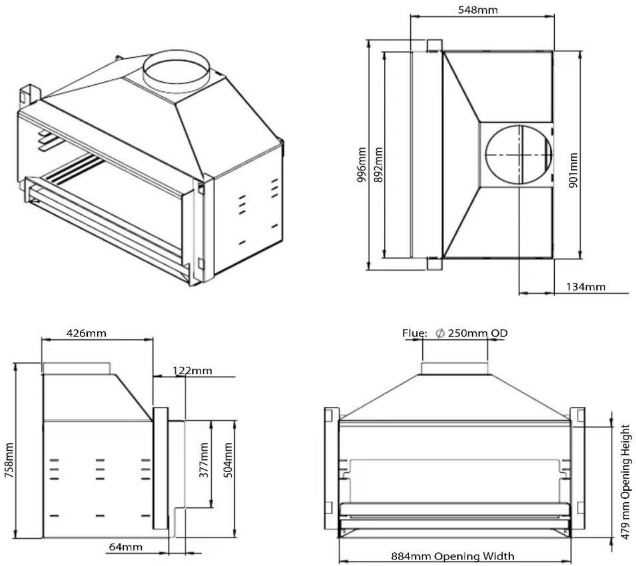
For Installations Without Fascia:
| EW5000 Specifications (No Fascia) | |
| Appliance Dimensions(mm): 996W x 758H x 548D | |
| Appliance Weight(kg): 90.3kg | |
| Concrete or Concrete Block Structure | |
| Minimum Internal Cavity Dimensions (mm): 1077W x 835D | |
| Timber or Combustible Structure | |
| Minimum AAC Heat Cell Dimensions (mm): 1200W x 950H x 735D | |
| Minimum Cavity Dimensions (mm): 1270W x 1550H x 770D | |
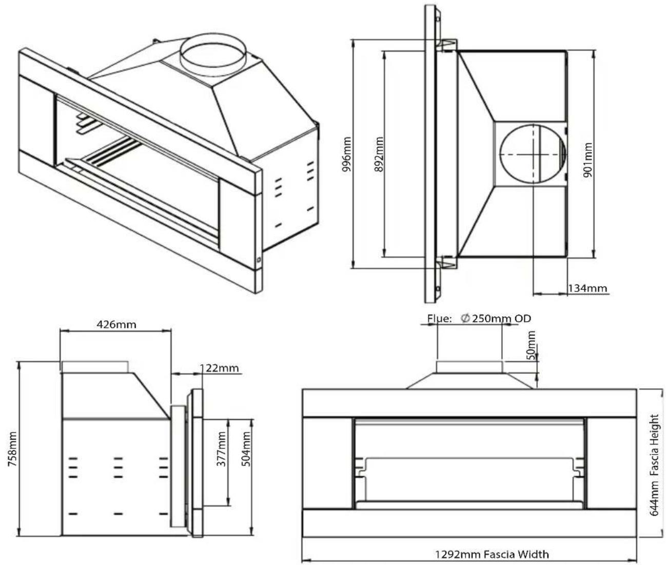
For Installations with Fascia:
| EW5000 Specifications (With Fascia) | |
| Appliance Dimensions(mm): 12 | 92W x 758H x 551 D |
| Appliance Weight(kg): 99.8kg | |
| Concrete or Concrete Block Structure | |
| Minimum Internal Cavity Dimensions (mm): 1077W x 835D | |
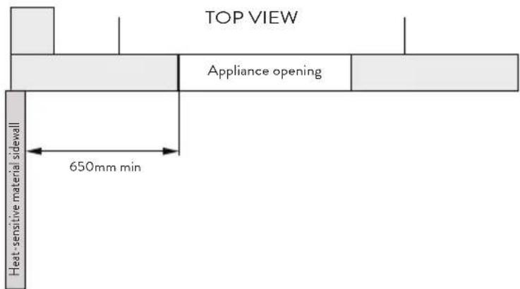
Any combustibles in front of the fireplace need to be no less than 2000mm from the opening of the fire and 650mm to each side. Any heat sensitive roofing/ceiling material above the fireplace must be no less than 1400mm from the appliance opening.
Also check with your city council (municipal authority) for local restrictions.
Note: The cavity structure must comply with the relevant section “D1 Minimum Requirements of Concrete | Concrete Blosk Structure” on page 11 or section “E1 Minimum Requirements of the Timber | Combustable Structure” on page 15, depending on the installation method of choice. For flue external clearances, refer to AS/NZS2918:2001.

D1 Minimum Requirements of Concrete | Concrete Block Structure
This appliance is designed for outdoor use ONLY.
The ESCEA EW5000 firebox and the flue system can be installed into a remote, free-standing, fully non-combustible fireplace construction on all surfaces surrounding the fireplace and flue. Example materials that can be used include: solid concrete, concrete/masonry blocks, bricks, or Hebel blocks/panels. Do not use timber framing.
For installations with a fascia, the position of the firebox must be located so that the appliance base is flush with the front face of the concrete structure. This is to allow the fascia to engage into the fascia brackets. Use the provided holes in the base to fix the firebox firmly down.
There are an additional 2 holes in the bottom corners of the rear panel. If these are not utilised as fixing holes, they should be ‘blanked off’ with a suitably sized nut and bolt (not supplied).
Depending on material choice, some heat may be conducted through the surrounding cavity and consequently no combustible materials should come into contact with these hot surfaces. This is completely dependant on the chosen material and design of installation. The user should satisfy themselves that the installation is fit for purpose and complies with all local and national codes.
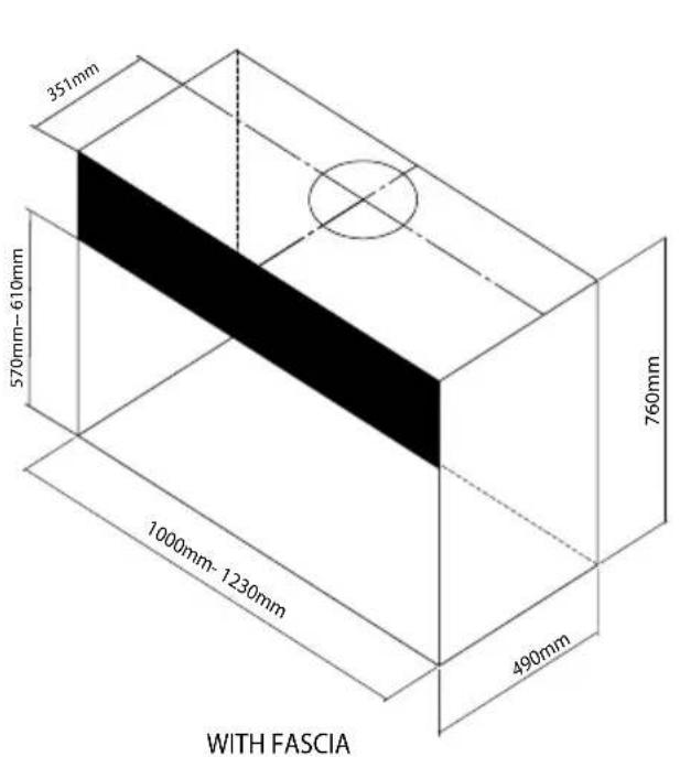
A minimum cavity size of W1000 x D490 x H760 mm is needed. This is the minimum size and where possible, it is recommended that the cavity is made slightly larger than the above dimensions to give the installer the maximum amount of space to work in.
For installations with a fascia: The opening of the cavity must be at minimum W1000 x H570mm and at maximum W1230 x H610mm in order for the fascia to cover the opening.
For installations without a fascia: The opening of the cavity must be W900 x H510mm
NOTE: The firebox does not slide in through this opening and has to be installed before the bricklaying or wall lining (hatched area shown below) is finished.
Note: If installing into a heat resistant material other than concrete, or if concrete thickness is less than 140mm- minimum clearance of 2000mm to any heat sensitive material applies.

Corner Installation

Venting Minimum Requirements for Concrete Structure
The air vent(s) can be any size or shape, provided that the total combined open surface area is at least 28600mm ^4 .
Vents are necessary in the structure, not higher than 300mm above the base of the fire. Vents must take air from outside. Venting air exits the structure through the flashing cone (supplied in Escea flue kit).
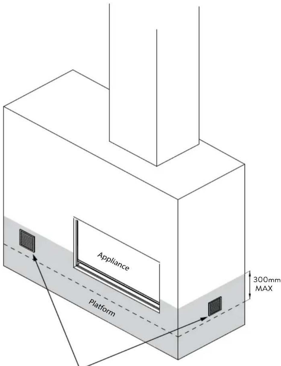
A total open surface area greater than 28600mm ^2 no higher than 300mm from the base of the appliance to vent the cavity.
D2 Sealing Requirements
All joints in the flue system and between the gather / chassis should be sealed with a suitable high temperature fire cement sealant that is able to operate at temperatures greater than 500°C. Care should be taken to ensure that the cavity is fully waterproof.
D3 Concrete | Concrete Block Structure Flue System Installation
Flue Specifications
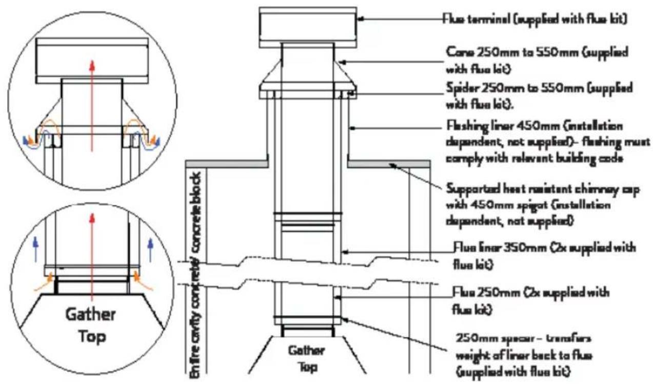
NOTE: THE APPLIANCE & FLUE SYSTEM SHALL BE INSTALLED IN ACCORDANCE WITH AS/NZS 2918 AND THESE SPECIFICATIONS.
Flue Installation- Order of Operations
- Install first length of flue, crimp down to fit into firebox spigot
- Install first length of liner, crimp up. Liner fits onto 250mm spacer (inverted with tabs upwards)
- Repeat steps 1 and 2 with remaining flue(s) and liner(s)
- Complete flashing of structure
- Attach spider to final length of flue, such that it spaces off liners appropriately
- Fit flashing cone
- Fit cowl
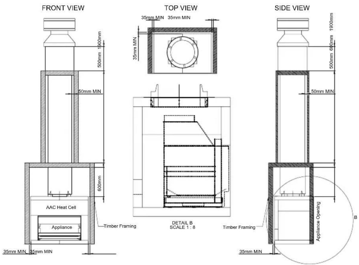
E1 Minimum Requirements of the Timber | Combustible Structure
The EW5000 appliance is designed for outdoor use ONLY. It can also be installed within a freestanding timber/combustible cavity. The cavity structure must be freestanding and must not be connected to the envelope of a building. However, the cavity can penetrate through a combustible roof structure. The roof structure may be attached to a building.
For this scenario, the appliance must be enclosed within an Autoclaved Aerated Concrete (AAC) heat cell with a minimum thickness of 75mm thick panels having a thermal resistance/ R-value of no less than 0.59m ^2 K/W. Additionally, the appliance must be installed with the EW Heat Cell Dropbox.
This scenario must be supplied with the triple skinned EW5000 Timber Cavity Flue Kit. The appliance must be frameless for this install scenario as the optional fascia is not compatible with this installation type.
Any cladding over the front of the structure (not including the chimney chase structure) must consist of a heat resistant material. Cladding over any other surface of the structure can consist of a combustible material (eg. plywood).
E2 Venting Minimum Requirements for Timber | Combustible Structure
The air vent(s) can be any size or shape, provided that the total combined open surface area is at least 94,600 mm ^2 .
Vents are necessary in the structure, not higher than 300mm above the base of the fire. Vents must take air from outside. Venting air exits through the flashing cone (supplied in Escea flue kit).

Venting Requirements:
EW5000: A total surface area of no less than 94,600mm ^2
Vents location no higher than 300mm above the base of the appliance.
Vents must take external/ outside air. If venting into a building cavity, ensure building cavity is balanced with outside air.
Vents can be in sides, at back or at front of cavity. Symmetry in venting orientation preferred.
E3 Sealing Requirements
All joints in the flue system and between the gather / chassis should be sealed with a suitable high temperature fire cement sealant that is able to operate at temperatures greater than 500°C.
Care should be taken to ensure that the cavity is fully weatherproof. Heat cell Dropbox should be sealed with high temperature resistant silicone sealant.
E4 Autoclaved Aerated Concrete (AAC) Heat Cell Assembly
Minimum Requirements of the Heat Cell
The AAC heat cell MUST be constructed around the appliance if installing into a timber/ combustible structure. AAC panels MUST be at least 75mm thick and must gave a thermal resistance/R-value of no less than 0.59m^2.K/W . The base of the heat cell must be constructed to the minimum dimensions prescribed to insulate the platform from the appliance.
The 'heat cell dropbox' (supplied separately) MUST be installed with the heat cell to comply.
Vents should be cut at the base of the heat cell, back panels, with an area of no less than 94,600mm^2 .
Note: The venting size requirement for the heat cell are different from the structure venting requirements.
E5 Heat Cell Construction Recommendations
Heat cell panels should be screwed together and bonded with a certified mortar (recommended by manufacturer) to ensure a tight seal.
The models shown in this document have a 5mm clearance from the AAC material to the firebox front flange, which should be altered depending on the chosen finishing method for the heat cell. Follow manufacturer's recommendations regarding finishing of the AAC material.
Note: To prevent the heat cell from cracking, it is recommended to light a few small fires first to dry out the AAC material.
EW5000 Heat Cell Dimensions
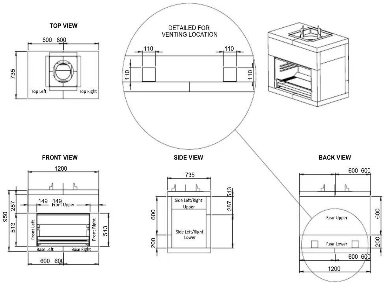
Note: Heat cell assemblies in this manual represent the minimum dimensions and are a guide only. The appliance opening is required to be recessed into the AAC structure to allow minimum thickness of 75mm.
EW5000 Heat Cell Cut Pattern
| BASE LEFT | BASE RIGHT |
| FRONT UPPER | REAR UPPER |
| REAR LOWER |
NOTE: THE APPLIANCE & FLUE SYSTEM SHALL BE INSTALLED IN ACCORDANCE WITH AS/NZS 2918 AND THESE SPECIFICATIONS
Flue Installation-Order of Operations
- Place bottom 250 spacer on first length of flue, at height such that the heat cell dropbox will rest on the spacer.
- Lift heat cell dropbox over flue onto bottom spacer.
- Install first length of flue together with spacer and dropbox. Install flue crimp down to fit into spigot on firebox gather. Dropbox should fit into square hole at top of heat cell.
- Place 250-350 spacer onto first length of flue, near top.
- Install first length of inner liner, crimp down. Liner fits to dropbox, on the inside of the dropbox's upright tabs.
- Place 350-450 spacer onto first inner liner, near top.
- Install outer liner, crimp down. Outer liner sits on the dropbox's upright tabs.
- Install further lengths of flue, inner and outer liners as required.
- Complete flashing of structure.
- Attach spider to final length of flue, such that it spaces off liners appropriately.
- Fit flashing cone.
- Fit cowl
Timber | Combustible Structure Flashing Options
Flashing with Chase Structure

Flashing through Roof

F1 Placement of Interior Parts
Placement of Interior Parts
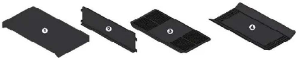
First, remove the following parts that are secured inside the firebox for transit; remove and discard of all protective packaging including the white plastic end caps.
natural_image
Four black plastic components with numbered labels, arranged in a row (no text or symbols on the parts themselves)Insert the Ash Pan (1) into the base of the fire as shown.

natural_image
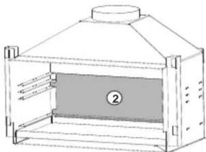
Line drawing of a simple enclosure with a chimney and internal structure, no text or symbols presentInsert the Rear Heat Deflector (2) into the fire as shown with the flange at the bottom facing forwards. The rear heat deflector fits in place by sitting inside the slots on the grate support brackets, which run along the side of the firebox.
natural_image
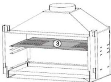
Technical line drawing of a 3D box-like structure with a central opening and top lid, no text or symbols present.For cooking, the Cooking Surface (3) can be placed on any of the three highest supports, depending of which height is desired. If not desired or when not in use, the cooking surface can be stored underneath the ash pan (bottom).
natural_image
Line drawing of a simple yurt with a lid and labeled component (no text or symbols)The cooking surface must be run on the fire for at least 1 hour prior to use to burn off any residual oils.
It is advisable that when not in use the cooking surface is covered in a layer of cooking oil to prevent corrosion.
Finally insert the Grate (4) on the lowest grate support bracket as shown, with the flanges facing upwards.

natural_image
Line drawing of a two-tiered industrial furnace or storage unit with a central column and top cover (no text or symbols)F2 Fitting the Fascia
If present, remove all protective film and packaging on the fascia before proceeding with install. Do not operate the fire with any protective film in place.

natural_image
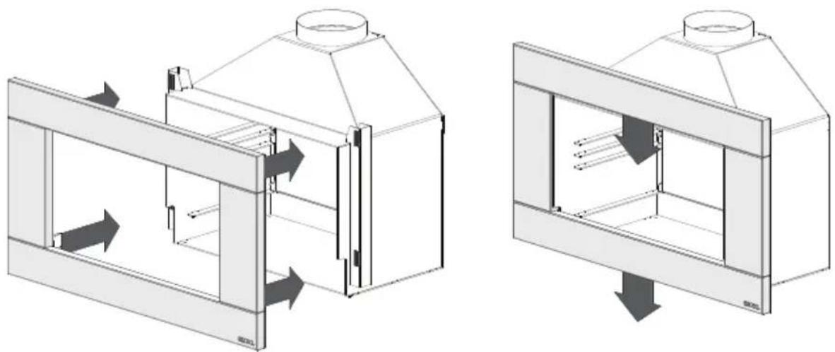
Technical line drawing of a mechanical assembly with an inset showing a close-up of a cylindrical component mounted on a platform (no text or symbols present)Before fitting the fascia, the hooks must be attached using the rivets supplied. The ESCEA EW5000 fascia is attached to the firebox by four 'hooks' on the corners of the fascia.
Line up the hooks with the receptacles on the wood burner pictured below and push the fascia into position. The first slot in the hook can be used to hang the fascia in the receptacles to ease the attachment.
When you have pushed the fascia in as far as it will go, briefly push down on the fascia to secure the fascia into position.
natural_image
Technical diagram showing two views of a mechanical or architectural component with directional arrows indicating flow or movement (no text or symbols present)To remove the fascia, simply reverse the operation.
A1 Fuel Selection
For optimal wood burning, use firewood with a moisture content of less than 20%.
Always use paper, firelighters, or finely split dry soft wood kindling to start a fire. Never use flammable liquid or aerosols. Do not burn treated or painted wood, plywood, MDF, particleboard, household rubbish, garden waste, plastics, waste oils, paint, construction or demolition waste. Some kinds of preservative-treated wood can be hazardous. It is recommended to use dry wood or charcoal only.
A2 Starting the Fire
The first fire may produce odors from the paint. If possible, light and maintain a small fire for a couple of hours; this will allow the paint to cure better.
To start the fire, stack kindling so that it leans against the back panels, allowing sufficient airflow between pieces. The use of fire-starters is recommended. Continue adding kindling until you have established an ember bed across the entire width of the fire.
Note: Expansion/contraction noises during heating up and cooling down cycles are normal and to be expected.
A3 Loading the Fire
Once an ember bed has been established, continue loading larger pieces of firewood onto the fire until the desired temperature or look has been reached. Ensure that all pieces of firewood do not protrude past the bottom stainless steel bar on the fireplace.
Always be careful not to overload the fire as this can result in over firing and logs falling out the front and cause a fire hazard.
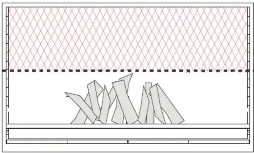
Do not load wood higher than 1/3 (33%) of the height of the firebox.
natural_image
Diagram showing a grid-patterned panel above a pile of triangular blades, with no text or symbols present.DO NOT load wood higher than 33% the height of the firebox
For an optimal lighting time, stack kindling vertically against the back of the firebox and use fire-starters to ignite the wood in a timely manner.
A1 Extinguishing the Fire
Once you have finished with burning the fire, remove all embers and remaining wood pieces from the fire and place them in a fireproof pail. Soak them well. Store them for a minimum of 5 days prior to disposing of them safely.
Supervise the fire until all logs and embers have been removed.
Note: The firebox will remain warm for several hours after the embers have been removed. Use caution when touching any parts of the firebox (i.e. the bricks, pivot drawer, or back panels) and supervise small children until the firebox has cooled completely.
If you need to extinguish a fire quickly, smother it with loose soil or sand. Avoid using water, except in emergencies, as this may lead to the development of rust if not dried completely. Never leave a lit fire unattended.
Do not place the baking plate directly over flames. Wait until the fire has burnt down to embers or use charcoal.
The ash pan should be removed and cleaned out before it is completely full. To get access to the ash pan, first remove the fascia (see correct operation). Ensure the pan and ashes are cool before handling.
It is very important that the flue is swept and cleaned for soot to reduce the risk of a chimney fire and to ensure the performance of the fireplace. This should be done at least once a year, as soot can build up quickly. Cold climate or burning of green or wet timber can increase soot buildup.
To keep the fire clean, sweep the firebox with a soft cloth when the firebox is cool. Never try to clean the firebox or fascia when they are hot. Cleaning the firebox at the end of the season and spraying with high temperature Stove bright paint will extend the life of your firebox. Ensure all surfaces are perfectly cleaned before applying paint.
Cleaning the Fascia
The fascia must be cold before starting any form of cleaning.
For cleaning a stainless steel fascia, 3M Stainless steel cleaner or a clean cloth with methylated spirits are recommended.
The fascia may discolour after use. A gentle wipe with soapy water and a soft cloth should remedy this and is recommended after every use.
Chimney Maintenance
The chimney must be inspected & cleaned at least once per year.
A chimney fire can permanently damage your chimney system; this damage can only be repaired by replacing the damaged component parts.
Chimney fires are not covered by the warranty.
Recommended Refurbishment Products
Senotherm UHT 600 Black - High Temp Spray Paint
ONLY this product may be used on all black painted surfaces and is available from your Escea dealer.
Before application, ensure any corrosion is removed by a wire brush; also ensure that the surface is clean and free of any dust.
There is no guarantee the parts can be returned to a new finish.
GENERAL WARRANTY TERMS AND CONDITIONS
General Information
This quality manufactured product is state of the art. The materials used were meticulously selected and are constantly checked, as is our entire production process.
Setting up or installing this product requires specialised knowledge. Escea products may therefore only be installed and commissioned by specialised firms and in compliance with statutory regulations as amended.
Warranty Conditions for Escea Outdoor Wood Fires
This warranty is provided by Escea Limited (referred to in this document as Escea). The warranty applies from the date of purchase from or through an authorised Escea dealer.
Nature of Warranty
Subject to the exclusions in section 2 & 3, Escea may undertake to put right any defects in the Escea Outdoor Wood Fire products supplied by Escea for the periods specified below:
| Parts Parts and Labour Warranty | |
| Basic firebox**: the steel body of the product only | 5 years* |
| Any removable part, including: top combustion panel, back panels, cooking plates, ember generator, pivot drawer, operation devices such as handles, adjustment levers | 2 year* |
* From date of purchase
** Failure is considered a physical crack or hole that stops the fire functioning as it is designed to.
Escea must pre-authorise all warranty work.
The benefits provided under this warranty are in addition to the consumer guarantees and any other statutory rights you may have under the consumer law and/or other applicable laws.
Warranty Exclusions
This warranty does not apply and will be void where:
- The Escea Outdoor Wood Fire is not installed in accordance with AS/NZS 2918 and any building code and consent (if required).
- The Escea Outdoor Wood Fire has not been installed or operated in accordance to the Escea Outdoor Wood Fire installation manual, in particular, defects, malfunctions or failures caused by incorrect installation, normal wear and tear, misuse, neglect, lack of proper and regular maintenance, accidental damage, any other alteration, or failure to follow operating
- The use of products, including flue systems, that are not specified in accordance with the installation manual.
- Repairs or modifications by persons not authorised by Escea, use of parts not supplied by Escea, or damage or other events which have occurred since the product left the control of Escea.
- Any scratches, dints, finger print marks, and melted items that occurred after the arrival of the product to the Escea Dealer.
- Discolouration of the painted surfaces, caused by soiling by soot or built-in residues of burnt materials as well as visibly changed colour or other aspects due to thermal stress or overloading.
- Changes in the interior / exterior surfaces of the house, fire, or flue (e.g. any staining or soot / smoke damage, cracking, discoloration or degradation of surfaces caused by thermal stress or overloading).
- Damage caused by abnormally corrosive environments (e.g. sea salt corrosion).
- Escea wood fires are coated with high temperature paint that may show signs of surface rust if exposed to moisture for an extended period of time. Any repair and replacements of parts that are subject to normal wear and tear expected with any outdoor fire product. Any rust damage discolouration or corrosion in any part of the fire over life of the fire is not covered by warranty.
- Damage caused by water affecting the Escea outdoor wood fire.
• Operation of the Escea outdoor wood fire without its back panel.
• Damage caused by chimney fires. - This warranty does not cover paint blemishes or imperfections because of the uneven nature of high temperature paint. A spray can of touch up paint is available at a local Escea retailer.
- Subject to any statutory provisions to the contrary, at Escea's discretion, Escea's liability in respect of EW5000 Series products that are found to have manufacturing defects will be limited to refunding, repairing, or replacing the defective products. The reinstatement and replacement of any affected outside wall, ceiling, or floor coverings, coatings, or claddings are not covered by warranty. Escea does not accept liability for consequential damage or any incidental expenses resulting directly or indirectly from any defect or breach of warranty, claims for damage to building or any other consequential loss.
Other Escea Outdoor Wood Fire Warranty Conditions
No dealer, distributor, or similar person has the authority to warrant Escea products beyond the terms contained in this warranty.
This warranty is automatically voided if the appliance's serial number has been removed or altered in anyway.
Any differences in fireplace appearance from Escea promotional images that is due to printing limitations, environmental factors, or wood variations are not a warranty issue.
Where you make a claim under this warranty, an authorised repairer may need to attend your premises to inspect the Escea product. Escea may charge you a service call fee if a repairer will be required to travel more than 30 km from the nearest service centre to your location. You can obtain details on the location of service centres and service call fees by visiting the Escea website or calling the customer care line below.
Warranty Claims
If you make a valid claim under warranty and none of the exclusions set out in section 2 and 3 apply, Escea will, at Escea's election either:
Repair the relevant part of the Escea product; or
Replace the relevant part of the Escea product with a product of identical specification (or where the product is superseded or no longer in stock, with a product of as close a specification as possible).
How to Make a Warranty Claim
To make a valid claim under this warranty, you must:
- Lodge the claim through the dealer who supplied the fire, as soon as you first become aware of the breakdown. The Escea Dealer will then follow Escea's warranty claim process.
- Provide the Escea product serial number.
- Provide reasonable proof of purchase for the Escea product.
- If required, provide access to the premises at which the Escea product is located (so it can be inspected).
| Regions Escea Distributors Filing a Claim | ||
| Australia Escea Australia | PTY Ltd.P.O. Box 176Pennant Hills, 1715, Sydney, NSWAU: 1800 460 832 or WA: 1800 730 140www.escea.com.au | Visit the distributor website or call distributor directly. |
| New Zealand Escea Ltd. | 17 Carnforth StreetDunedin, 9018, New Zealand0800 17 3000www.escea.com | Contact the dealer you purchased the fire from |
- ESCEA FIREPLACE KITCHEN
- Installation Instructions and User Guide
- NOTICE
- WARNING
- CAUTION: THE USE OF SOME TYPES OF PRESERVATIVE-TREATED WOOD AS FUEL CAN BE HAZARDOUS.
- B1 Product Description
- B2 Installation Scenarios
- Concrete/ Masonry Cavity
- Timber/ Combustible Cavity
- Kitset Enclosure
- B3 Product Dimensions
- For Installations Without Fascia:
- D1 Minimum Requirements of Concrete | Concrete Block Structure
- Venting Minimum Requirements for Concrete Structure
- D2 Sealing Requirements
- D3 Concrete | Concrete Block Structure Flue System Installation
- Flue Specifications
- Flue Installation- Order of Operations
- E1 Minimum Requirements of the Timber | Combustible Structure
- E2 Venting Minimum Requirements for Timber | Combustible Structure
- Venting Requirements:
- E3 Sealing Requirements
- E4 Autoclaved Aerated Concrete (AAC) Heat Cell Assembly
- Minimum Requirements of the Heat Cell
- E5 Heat Cell Construction Recommendations
- EW5000 Heat Cell Cut Pattern
- Flue Installation-Order of Operations
- Timber | Combustible Structure Flashing Options
- F1 Placement of Interior Parts
- F2 Fitting the Fascia
- A1 Fuel Selection
- A2 Starting the Fire
- A3 Loading the Fire
- A1 Extinguishing the Fire
- Cleaning the Fascia
- Chimney Maintenance
- Recommended Refurbishment Products
- Senotherm UHT 600 Black - High Temp Spray Paint
- GENERAL WARRANTY TERMS AND CONDITIONS
- General Information
- Warranty Conditions for Escea Outdoor Wood Fires
- Nature of Warranty
- Warranty Exclusions
- Other Escea Outdoor Wood Fire Warranty Conditions
- Warranty Claims
- How to Make a Warranty Claim
Brand : Escea
Model : EW5000
Category : Heating