nWall 1.1 - Amplifier MediaMatrix - Free user manual and instructions
Find the device manual for free nWall 1.1 MediaMatrix in PDF.

User questions about nWall 1.1 MediaMatrix
0 question about this device. Answer the ones you know or ask your own.
Ask a new question about this device
Download the instructions for your Amplifier in PDF format for free! Find your manual nWall 1.1 - MediaMatrix and take your electronic device back in hand. On this page are published all the documents necessary for the use of your device. nWall 1.1 by MediaMatrix.
USER MANUAL nWall 1.1 MediaMatrix
A Division of Peavey Electronics Corporation

natural_image
Simple line drawing of a computer with a book and mouse (no text or symbols)
text_image
MediaMatrix® Porphy Electronics Corporation mic input mic input L+R sum ? line in gain L+R sum ? line in gain nWallnWall Hardware Manual
Version 2.0.0.0
July 7, 2017
Copyright notice
The information contained in this manual is subject to change without notice. Peavey Electronics is not liable for improper installation or configuration. The information contained herein is intended only as an aid to qualified personnel in the design, installation and maintenance of engineered audio systems. The installing contractor or end user is ultimately responsible for the successful implementation of these systems.
All creative content in this manual, including the layout, art design, content, photography, drawings, specifications and all other intellectual property is Copyright © 2016 Peavey Electronics Corporation. All Rights Reserved. Features & specifications subject to change without notice. All other registered trademarks or trademarks are the property of their respective owners.
Email:mmtechsupport@peavey.com (mailto:mmtechsupport@peavey.com).
Scope
This guide describes how to install an nWall device and how to connect the device to the network.
Contents
Chapter 1 Important safety instructions....1
Safety warnings....2
Chapter 2 Before you start....5
Important network considerations 6
Warranty Registration....6
What you will need 6
What's in the box? 6
Thank You! 6
Chapter 3 Introduction to nWall ....7
Description....8
Features....9
Rear Panel Connections....11
Chapter 4 Infrastructure design considerations....13
Introduction....14
2-gang NEMA electrical enclosures ....14
Providing power to nWall devices 14
Chapter 5 Installing and connecting the nWall....17
Installing the nWall 18
Connecting audio devices to the nWall 19
Assigning an IP address using CobraNet Discovery....19
Assigning a bundle number using CobraNet Discovery....20
Assigning a bundle number using NWare....21
Replacing an nWall....23
Warranty statement....25
Chapter 1
Important safety instructions
In This Chapter
Safety warnings 2
Safety warnings
Warning: When using electrical products, basic cautions should always be followed, including the following:
- Read these instructions.
- Keep these instructions.
- Heed all warnings.
- Follow all instructions.
- Do not use this apparatus near water.
- Clean only with a dry cloth.
- Do not block any of the ventilation openings. Install in accordance with manufacturer's instructions.
- Do not install near any heat sources such as radiators, heat registers, stoves or other apparatus (including amplifiers) that produce heat.
- Do not defeat the safety purpose of the polarized or grounding-type plug. A polarized plug has two blades with one wider than the other. A grounding type plug has two blades and a third grounding plug. The wide blade or third prong is provided for your safety. If the provided plug does not fit into your outlet, consult an electrician for replacement of the obsolete outlet.
- Protect the power cord from being walked on or pinched, particularly at plugs, convenience receptacles, and the point they exit from the apparatus.
- Only use attachments/accessories provided by the manufacturer.
- Use only with a cart, stand, tripod, bracket, or table specified by the manufacturer, or sold with the apparatus. When a cart is used, use caution when moving the cart/apparatus combination to avoid injury from tip-over.
- Unplug this apparatus during lightning storms or when unused for long periods of time.
- Refer all servicing to qualified service personnel. Servicing is required when the apparatus has been damaged in any way, such as power-supply cord or plug is damaged, liquid has been spilled or objects have fallen into the apparatus, the apparatus has been exposed to rain or moisture, does not operate normally, or has been dropped.
- Never break off the ground pin. Write for our free booklet Shock Hazard and Grounding. Connect only to a power supply of the type marked on the unit adjacent to the power supply cord.
- If this product is to be mounted in an equipment rack, rear support should be provided.
- Control panel devices, including the xControl range, D series and nTouch 60, are designed for mounting in NEMA metal enclosures. Grounding to the front plate is required.
- Note for UK only: If the colors of the wires in the mains lead of this unit do not correspond with the terminals in your plug, proceed as follows:
a) The wire that is colored green and yellow must be connected to the terminal that is marked by the letter E, the earth symbol,
b) colored green or colored green and yellow.
c) The wire that is colored blue must be connected to the terminal that is marked with the letter N or the color black.
d) The wire that is colored brown must be connected to the terminal that is marked with the letter L or the color red.
-
This electrical apparatus should not be exposed to dripping or splashing and care should be taken not to place objects containing liquids, such as vases, upon the apparatus.
-
The on/off switch in this unit does not break both sides of the primary mains. Hazardous energy can be present inside the chassis when the on/off switch is in the off position. The mains plug or appliance coupler is used as the disconnect device, the disconnect device shall remain readily operable.
-
Exposure to extremely high noise levels may cause a permanent hearing loss. Individuals vary considerably in susceptibility to noise-induced hearing loss, but nearly everyone will lose some hearing if exposed to sufficiently intense noise for a sufficient time. The U.S. Government's Occupational Safety and Health Administration (OSHA) has specified the following permissible noise level exposures:
| Duration Per Day in Hours | Sound Level dBA, Slow Response |
| 8 | 90 |
| 6 | 92 |
| 4 | 95 |
| 3 | 97 |
| 2 | 100 |
| 112 | 102 |
| 1 | 105 |
| 12 | 110 |
| 14 or less | 115 |
According to OSHA, any exposure in excess of the above permissible limits could result in some hearing loss. Ear plugs or protectors to the ear canals or over the ears must be worn when operating this amplification system in order to prevent a permanent hearing loss, if exposure is in excess of the limits as set forth above. To ensure against potentially dangerous exposure to high sound pressure levels, it is recommended that all persons exposed to equipment capable of producing high sound pressure levels such as this amplification system be protected by hearing protectors while this unit is in operation.
SAVE THESE INSTRUCTIONS!
Chapter 2
Before you start
In This Chapter
Important network considerations 6
Warranty Registration 6
What you will need 6
What's in the box? 6
Thank You! 6
Important network considerations
This product is designed to operate on a network backbone or infrastructure. The design, implementation and maintenance of this infrastructure is critical to correct operation and performance of the product. Peavey Electronics Corp does not support nor service network cabling, hubs, switches, patch bays, wall plates, connector panels or any other type of network interconnect device. Please ensure that these components and their associated installation techniques have been properly designed and installed for audio and network applications.
Warranty Registration
Please take a few minutes and fill out the warranty registration card. Although your warranty is valid without the registration, the information you provide with the form is crucial to our support group. It enables us to provide better service and customer support, and to keep you informed of new product updates.
Tip: Refer to the warranty statement at the rear of this manual for details of what your warranty includes and what the limitations are.
What you will need
Phillips head screwdriver to fit NEMA enclosure screws.
What's in the box?
In the box you will find:
The nWall
- Four screws, which are used to securely install the nWall in a NEMA electrical enclosure.
Thank You!
Thank you for purchasing this MediaMatrix product. It is designed to provide years of trouble-free operation and high quality performance. We are confident that you will find this product and other MediaMatrix products to be of the highest quality.
Chapter 3
Introduction to nWall
In This Chapter
Description 8
Features....9
Rear Panel Connections 11
Description
The nWall is a CobraNet interface panel with both XLR and TRS mini jack connectors. The nWall 2.0 has two microphone/line level input channels. The nWall 0.2 has two analog line level output channels. The nWall 1.1 has two analog line level input channels and two analog line level output channels.
The nWall eliminates the need for long runs of analog audio cables terminated in racks of patch bays, as typically seen in ballrooms and convention centers. As the connection to the nWall uses CAT5e UTP cable with network standard RJ45 crimp connectors, the installation time, number of terminations required and associated cost are all minimized.
In the example below, the audio from the mics is made available directly onto the CobraNet network without the need for a CAB or NION in the same physical location. The NWare project is hosted on the nControl, allowing the NWare user to remotely assign a bundle number to the nWall for audio transmission.
Note: If you want to control and monitor an nWall using an NWare project, you will need an nControl or nTouch 180. If you simply want to transmit or receive audio using an nWall, these devices are not required. You can use CobraNet Discovery to configure and monitor the nWall.

flowchart
graph TD
    A["Zone A"] --> B["CAB 8n"]
    C["Zone B"] --> B
    D["Zone C"] --> B
    B --> E["Ethernet network"]
    E --> F["CobraNet connection"]
    F --> G["nWall 2.0"]
    G --> H["PA system mics"]
    I["NION"] --> E
    J["nControl"] --> E
    K["PC running NWare"] --> E
    L["Audio cables"] --> B
    M["Crest amplifier"] --> B
    N["Control network connection"] --> E
Features
All models
- Digital patching - using MediaMatrix NWare, any number of nWall panels can be patched to any number of NION processors on the fly, eliminating the need for expensive patch panels and greatly reducing setup time between events.
- Analog to digital / digital to analog conversion at the wall panel reduces problems with buzz, hum, ground loops and other cable issues, also eliminating the need for isolation and impedance matching interfaces.
■ Structured cabling to greatly reduce critical path delivery time and costs.
■ Power over Ethernet (PoE).
■ Low power requirements.
■ 2-gang NEMA mount.
■ CobraNet audio transport via switched network and RJ45.
■ Easy wiring and installation.
■ Cost effective.
nWall 0.2
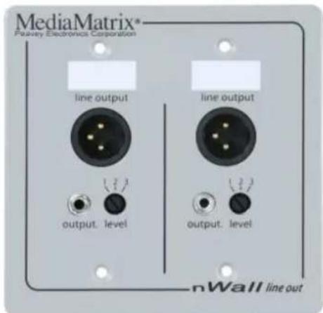
text_image
MediaMatrix® Feasley Electronics Corporation line output output. level line output output. level nWall line out- 2 balanced XLR outputs - output level selectable via front panel 3 step rotary switch allows quick source setup at the wall panel. Latchless connection minimizes mechanical damage.
■ 2 unbalanced TRS 1/8th inch (3.5mm) mini jack outputs - for PC and Aux consumer line level audio products using off the shelf consumer audio cables.
nWall 1.1
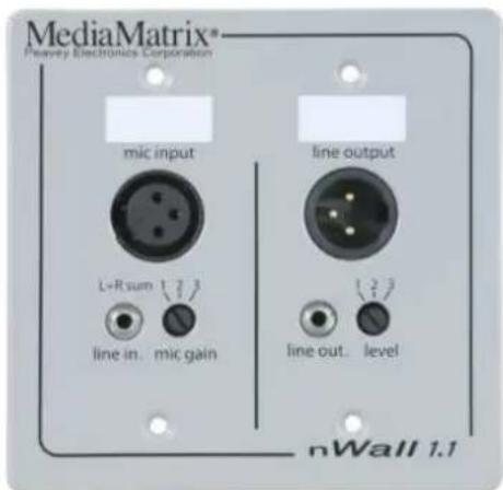
text_image
MediaMatrix® Peavley Electronics Corporation mic input line output L+R sum line in. mic gain line out. level nWall 1.1- 1 balanced XLR input connector - selectable input sensitivity via rotary switch. Latchless connection minimizes mechanical damage.
- 1 balanced XLR output connector - selectable output level via rotary switch. Latchless connection minimizes mechanical damage.
■ 1 unbalanced TRS 1/8th inch (3.5mm) mini jack input connector - for Electret condenser and dynamic microphones, plus line level audio products. - 1 unbalanced TRS 1/8th inch (3.5mm) mini jack output connector - for PC and Aux consumer line level audio products.
nWall 2.0
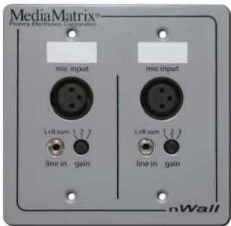
text_image
MediaMatrix™ Microelectronics Corporation mic input mic input L+R sum 3 line in gain L+R sum 3 line in gain nWall- 2 balanced XLR inputs - mic/line selectable gain via front panel 3 step rotary switch allows quick source setup at the wall panel. Latchless connection minimizes mechanical damage.
■ 2 unbalanced TRS 1/8th inch (3.5mm) mini jack inputs - summed mono for PC and Aux consumer line level audio products using off the shelf consumer audio cables.
Rear Panel Connections
The rear panel contains a LAN socket for CobraNet and control communications on 100Base-T Ethernet. It requires a Power-over-Ethernet (PoE) injector or PoE via an IEEE 802.3af capable network switch.
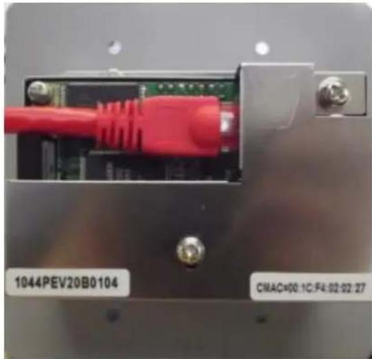
natural_image
Close-up of a red USB cable connector with labeled ports (no readable text beyond labels)Chapter 4
Infrastructure design considerations
In This Chapter
Introduction ...... 14
2-gang NEMA electrical enclosures 14
Providing power to nWall devices 14
Introduction
Before you start the installation, it is important to consider the implications for your network and power supply system. The infrastructure must be designed and installed correctly, in order to provide reliable and error-free performance.
Each nWall unit requires a network connection to a network switch. There are several configurations you can use, allowing for a degree of flexibility in your installation.
2-gang NEMA electrical enclosures
nWall units are designed to mount in standard NEMA electrical enclosures. This includes boxes designed for fixed installation into sheet rock, wood or masonry construction. All cabling and terminations should be installed into EMT conduit, securely coupled to the mounting box and system ground plane. However, the nWall is not grounded through the network cable. It should be installed in a metal 2-gang NEMA electrical enclosure that is grounded according to the directives set forth by the authority having jurisdiction.
Providing power to nWall devices
Power can be supplied to nWall devices via an injector or Power over Ethernet (PoE) switch. The nWall devices do not require separate power connections. An example is shown below.
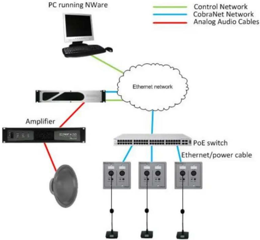
flowchart
graph TD
    A["PC running NWare"] --> B["Ethernet network"]
    B --> C["Amplifier"]
    C --> D["Power cord"]
    B --> E["PoE switch"]
    E --> F["Ethernet/power cable"]
    style A fill:#f9f,stroke:#333
    style B fill:#ccf,stroke:#333
    style C fill:#cfc,stroke:#333
    style D fill:#fcc,stroke:#333
    style E fill:#cff,stroke:#333
    style F fill:#ffc,stroke:#333
Chapter 5
Installing and connecting the nWall
In This Chapter
Installing the nWall 18
Connecting audio devices to the nWall 19
Assigning an IP address using CobraNet Discovery.... 19
Assigning a bundle number using CobraNet Discovery .... 20
Assigning a bundle number using NWare 21
Replacing an nWall 23
Installing the nWall
- Insert a cable from a CobraNet PoE switch into the back of the nWall, as shown below.

natural_image
Close-up of an electronic device showing a red RJ4 connector inserted into a black circuit board (no visible text or symbols on the main subject)-
Carefully place the nWall into a 2-gang NEMA box.
-
Insert and tighten the screws.
text_image
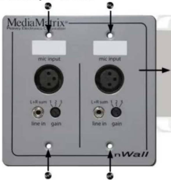
MediaMatrix™ Primary Electronics Organization mic input mic input L+R sum 1.2.3 line in gain L+R sum 1.2.3 line in gain nWallConnecting audio devices to the nWall
▶ To connect input devices
- Under mic input, plug balanced sources (microphones and line level devices) into the XLR connector(s) and unbalanced sources (computers, personal music players, etc.) into the 3.5mm TRS mini jack(s).
- Select the mic gain level using the rotary switch(es).
▶ To connect output devices
- Under line output, connect devices to the XLR connector(s) and 3.5mm TRS mini jack(s).
- Select the output level using the rotary switch.
Assigning an IP address using CobraNet Discovery
In order to contact an nWall to assign bundle numbers or change other CobraNet settings, the device must be assigned an IP address. This must be done using CobraNet Discovery.
CobraNet Discovery (DISCO) is a monitoring, troubleshooting and maintenance tool for CobraNet networks. It uses a standard Ethernet network interface card (NIC) to connect to the network. The application discovers devices and displays status information for each of them. It also allows you to configure devices and perform firmware upgrades.
If you have installed DISCO, you can refer to the user manual for information on how to use the software. It is installed in the same folder as the program. Also see http://www.cobranet.info/downloads/disco (http://www.cobranet.info/downloads/disco).
Once you have assigned an IP address to an nWall, CobraNet Discovery will retrieve information from the nWall, including the name and description, and allow you to specify configuration settings.
When you have configured the nWall, we recommend using the persistence option to ensure that the same settings are used automatically when the nWall is power cycled.
The procedure below assumes that you are using a PC connected to the CobraNet network and CobraNet Discovery is installed and running.
Note: The steps in the procedure below must be completed for each individual nWall. If an nWall is replaced, you will need to repeat the procedure.
▶ To set an IP address
-
Open CobraNet Discovery and wait for the nWall to appear in the list of devices on the CobraNet network. The nWall MAC address starts with 00:1c:f4:02. It is normally printed on a label attached to the rear of the unit.
-
If you want to assign an IP address manually to the nWall, right-click the nWall device, click New IP Address, then specify an IP address. If you want an IP address to be assigned automatically, you can use the Auto Assignment feature to assign IP addresses to all devices on the CobraNet network automatically. On the Tools menu, click Options, and then select the Enable Auto Assignment check box.
-
Click OK.
When an IP address has been assigned, CobraNet Discovery will retrieve the name and description from the nWall. This information can then be used in NWare to identify the device on the network.
To ensure that the same settings are used when the unit is power cycled
- Right-click the nWall device, and then click Configure.
- Click Advanced and then select the Persistence check box.
- Click OK.
- Click OK.
Assigning a bundle number using CobraNet Discovery
Once you have assigned an IP address to an nWall, CobraNet Discovery will retrieve information from the nWall, including the name and description, and allow you to specify configuration settings.
When you have configured the nWall, we recommend using the persistence option to ensure that the same settings are used automatically when the nWall is power cycled.
The procedure below assumes that you are using a PC connected to the CobraNet network and CobraNet Discovery is installed and running.
Note: The steps in the procedure below must be completed for each individual nWall. If an nWall is replaced, you will need to repeat the procedure.
To set a transmit or receive bundle number
- In the list of devices, right-click the nWall device, and then click Configure.
- Double-click an RX or TX entry in the bundle list, and then specify a bundle number in the Bundle box.
Note: Be sure to check which model of nWall is being configured (on page 9). Some devices support transmission and reception, others only one or the other mode.
- Click OK.
- Click OK.
To ensure that the same settings are used when the unit is power cycled
- In the list of devices, right-click the nWall device, and then click Configure.
- Click Advanced and then select the Persistence check box.
- Click OK.
- Click OK.
Assigning a bundle number using NWare
Setting up the nControl or nTouch 180
In order to monitor and configure an nWall from NWare, you will need an nControl or nTouch 180 connected to both the control network and the CobraNet network. The example below shows the required setup for an nControl.

flowchart
graph TD
    A["Ethernet network"] -->|CobraNet connection| B["nWall"]
    C["Ethernet port 1"] --> A
    D["Ethernet port 2"] --> A
    E["PC running NWare"] --> F["Control network connection"]
Before you start using NWare to connect to the nWall, it is important to check that the network settings for the connection to the CobraNet network are correct. In the procedure below, it is assumed that Local Area Connection 1 is connected to the control network and Local Area Connection 2 will be used for the CobraNet network. For information on the nControl network ports, see Rear network ports in the nControl Hardware Manual.
To set up the nControl or nTouch 180
-
Open a web browser, then connect to the nControl or nTouch 180 web interface.
-
On the Network screen, under Local Area Connection 2, check that the network settings are correct for the CobraNet network.
If no DHCP server is available, you will need to use a static IP address.
- Click Set to confirm the action.
You will be asked to log on.
- Specify your username and password. The default username is superuser; it has no password.
Setting the bundle number in NWare
-
In the device tree, expand the Plugins / Peavey / Hardware / nWall folder.
-
Drag an nWall device over to the design page.
Select an nWall device that matches the model of nWall you are using.
-
Double-click the nWall device block to show the control surface.
-
In the IP address box, type the IP address of the nWall.
Tip: If you do not know the IP address, you can use a different method to contact the nWall from NWare. For more information, see Connecting to the nWall when you do not know the IP address (on page 22).
When NWare contacts the nWall, the Link LED will be lit. If the nWall is transmitting or receiving audio, the Transmitting and Receiving LEDs will be lit.
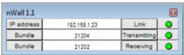
text_image
nWall 1.1 IP address 192.168.1.23 Link Bundle 21204 Transmitting Bundle 21202 Receiving- If you want to use different bundle numbers to those shown, type the new bundle numbers in the Bundle boxes.
Connecting to the nWall when you do not know the IP address
If you do not know the IP address of the nWall, you can use the Agent Discovery device in NWare to discover the nWall on the CobraNet network, and retrieve its IP address.
A range of different identifiers can be used to locate the nWall. These are specified on the control surface of the Agent Discovery device, in order to start the discovery process.
■ MAC address
- Sys Object ID
- Sys Name
- Sys Contact
- Sys Location.
This method utilizes the BOOTP and SNMP features of the nControl or nTouch 180. It is especially helpful and suited for larger installations, as it uses switch port discovery.
Note: Even though the discovery process will find the IP address of the nWall, you will still need to specify an IP address range that includes the IP address of the nWall.
To contact the nWall when you do not know the IP address
- In the device tree, expand the Hardware folder.
- Drag an nControl or nTouch 180 device over to the design page.
- In the device tree, expand the Plugins / Peavey / Hardware / nWall folder.
- Drag an nWall device over to the design page.
- Open the device properties on the nControl / nTouch 180.
- Select the CobraNet BOOTP check box.
- Select the SNMP Discovery check box.
- Click OK.
- On the Configure BOOTP Server dialog box, specify an IP address range for the nWall nodes on the CobraNet network.
- Click OK.
- On the Configure Discovery Server dialog box, specify the IP address range to use with BOOTP, and select the Switch port support check box.
- In the Update period (mins) box, type a value for the interval between scans for devices on the network.
- Click OK.
-
In the device tree, expand the nControl Devices / SNMP Components folder, and then drag an Agent Discovery device over to the design page.
-
Select Wire mode 📋, then wire the first output wiring node on the Agent Discovery block to the input wiring node on the nWall block.
-
Deploy the project and specify an identifier for the nWall using the Agent Discovery device.
Tip: You can use the Sys Name setting, for example, which is CS18100, by default.
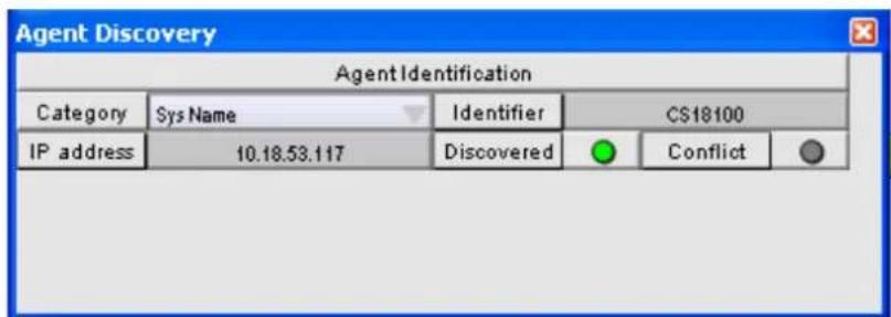
text_image
Agent Discovery Agent Identification Category Sys Name Identifier CS18100 IP address 10.18.53.117 Discovered ConflictWhen the nWall has been discovered, its IP address will be displayed in the IP address box on the Agent Discovery device, and on the nWall device. When NWare contacts the nWall using the IP address, the Link LED on the nWall device will be lit.
Replacing an nWall
This section describes what to do when you want to physically remove an nWall from the CobraNet network and replace it with another nWall. You may want to do this, for example, to provide audio inputs as well as outputs at a particular location, and this requires a different model of nWall to be used.
▶ Disconnecting the current nWall
- Physically locate the nWall.
- Make a note of which audio cables are plugged into which ports on the front of the nWall, so they can be plugged into the same ports on the replacement unit.
- Unplug any audio cables connected to the front panel of the nWall.
- Remove the screws securing the nWall into the NEMA box.
- If several CobraNet network cables are nearby, make a note of which one is being used with the nWall.
- Unplug the CobraNet network cable from the back of the nWall.
Connecting the replacement nWall
- Connect the new nWall to the CobraNet network.
- Fasten the screws to secure the nWall into the NEMA box.
- Plug the audio cables into the new nWall.
▶ Specifying the IP address and bundle numbers
- Assign an IP address to the nWall (on page 19).
- Assign a bundle number to the nWall using CobraNet Discovery (on page 20) or NWare (on page 21).
Warranty statement
MediaMatrix®
PEAVEY ELECTRONICS CORPORATION
DOMESTIC (USA) LIMITED WARRANTY
Effective Date: May 1, 2005
What This Warranty Covers
This Warranty covers defects in material and workmanship in Peavey MediaMatrix products purchased and serviced in the United States of America (USA).
What This Warranty Does Not Cover
The Warranty does not cover: (1) damage caused by accident, misuse, abuse, improper installation or operation, rental, product modification or neglect; (2) damage occurring during shipment; (3) damage caused by repair or service performed by persons not authorized by Peavey; (4) products on which the serial number has been altered, defaced or removed; (5) products not purchased from an Authorized MediaMatrix Integrator. This warranty does not cover associated costs incurred from servicing equipment, including, but not limited to, travel, jobsite-related costs, fabrication, freight, loaner equipment, installation, cabling or harnessing, mounting materials or other variable costs.
Who This Warranty Protects
In applications where the product is sold over the counter, this Warranty protects the original retail purchaser. In applications where the product is part of an integrated system, and such system is warranted by the integrator as a complete assembly, this Warranty protects only the system integrator.
What Peavey Will Do
We will repair or replace (at Peavey's discretion) products covered by warranty at no charge for labor or materials. If the product or component must be shipped to Peavey for warranty service, the consumer must pay initial shipping costs. If the repairs are covered by warranty, Peavey will pay the return shipping costs.
How Long This Warranty Lasts
The Warranty begins on the date of purchase by the original retail purchaser or on the date received by the system integrator. (See Who This Warranty Protects, above). The duration of the Warranty varies by product as summarized below.
| 5 Years | MediaMatrix® DPU cards, NIONTM Processing Nodes, CABs, I/O cards, Cinema Processors, Power Amplifiers, Pre-Amplifiers, Mixers, Electronic Filter Sets and Dynamics Processors. |
| 1 Year | MM Series Cardframes, MF Series Cardframes, ControlMatrixTM Host Processors, Servers and Controllers, nControl, nTouch 180, nTouch 60, xControl LCDs, nWall, VCAT, VCAT-HD, VGA-2, VSC, D4S, D1V, Remote Control Panels, Plates, Paging Stations, Ambient Sense Devices and other devices installed in user-accessible locations. |
| 90 Days | Loudspeaker Components (including speakers, baskets, drivers, diaphragm replacement kits and |
passive filter networks.) and all Accessory Products
How To Get Warranty Service
End Users: Take the defective product and your dated sales receipt or other proof of purchase to your Authorized MediaMatrix Systems Integrator or Authorized Peavey Service Center. System Integrators: Ship the defective product, prepaid, to Peavey Electronics Corporation, International Service Center, 412 Highway 11 & 80 East, Meridian, MS 39301, 601-483-5365. Include a detailed description of the problem, the name and location of the jobsite and a copy of your invoice as evidence of warranty coverage. Please include a complete return shipping address.
Limitation of Implied Warranties
ANY IMPLIED WARRANTIES, INCLUDING WARRANTIES OF MERCHANTABILITY AND FITNESS FOR A PARTICULAR PURPOSE, ARE LIMITED IN DURATION TO THE LENGTH OF THIS WARRANTY.
Some states do not allow limitations on how long an implied warranty lasts, so the above limitation may not apply to you.
Exclusions of Damages
PEAVEY'S LIABILITY FOR ANY DEFECTIVE PRODUCT IS LIMITED TO THE REPAIR OR REPLACEMENT OF THE PRODUCT, AT PEAVEY'S OPTION. IF WE ELECT TO REPLACE THE PRODUCT, THE REPLACEMENT MAY BE A RECONDITIONED UNIT. PEAVEY SHALL NOT BE LIABLE FOR DAMAGES BASED ON INCONVENIENCE, LOSS OF USE, LOST PROFITS, LOST SAVINGS, DAMAGE TO ANY OTHER EQUIPMENT OR OTHER ITEMS AT THE SITE OF USE, OR ANY OTHER DAMAGES WHETHER INCIDENTAL, CONSEQUENTIAL OR OTHERWISE, EVEN IF PEAVEY HAS BEEN ADVISED OF THE POSSIBILITY OF SUCH DAMAGES.
Some states do not allow the exclusion or limitation of incidental or consequential damages, so the above limitation or exclusion may not apply to you. This Warranty gives you specific legal rights, and you may also have other rights which vary from state to state. If you have any questions about this warranty or service received, or if you need assistance in locating an Authorized Service Center, please contact the Peavey International Service Center at (601) 483-5365. Features and specifications subject to change without notice.
MediaMatrix®
A Division of Peavey Electronics Corp.
5022 Hartley Peavey Drive, Meridian Mississippi, 39305, USA
Phone: 866.662.8750
hp://www.peaveycommercialaudio.com/products.cfm/mm/
Features & Specicaons subject to change without noce
Copyright © 2016, All Rights Reserved
80307511