LDP163-181 - Projector VIEWSONIC - Free user manual and instructions
Find the device manual for free LDP163-181 VIEWSONIC in PDF.

User questions about LDP163-181 VIEWSONIC
0 question about this device. Answer the ones you know or ask your own.
Ask a new question about this device
Download the instructions for your Projector in PDF format for free! Find your manual LDP163-181 - VIEWSONIC and take your electronic device back in hand. On this page are published all the documents necessary for the use of your device. LDP163-181 by VIEWSONIC.
USER MANUAL LDP163-181 VIEWSONIC
All-in-One Direct View LED Display User Guide
IMPORTANT: Please read this User Guide to obtain important information on installing and using your product in a safe manner, as well as registering your product for future service. Warranty information contained in this User Guide will describe your limited coverage from ViewSonic® Corporation, which is also found on our web site at http://www.viewsonic.com in English, or in specific languages using the Regional selection box of our website.
Model No. VS18885
P/N: LDP163-181
Thank you for choosing ViewSonic®
As a world-leading provider of visual solutions, ViewSonic® is dedicated to exceeding the world's expectations for technological evolution, innovation, and simplicity. At ViewSonic®, we believe that our products have the potential to make a positive impact in the world, and we are confident that the ViewSonic® product you have chosen will serve you well.
Once again, thank you for choosing ViewSonic®!
Safety Precautions
Please read the following Safety Precautions before you start using the device.
- Keep this user guide in a safe place for later reference.
- Read all warnings and follow all instructions.
- Ensure there is no direct airflow from air conditioning blowing on the display.
- Do not use the device near water. To reduce the risk of fire or electric shock, do not expose the device to moisture.
- Avoid exposing the device to direct sunlight or other sources of sustained heat.
- Do not install near any heat sources such as radiators, heat registers, stoves, or other devices (including amplifiers) that may increase the temperature of the device to dangerous levels.
- When moving the device, be careful not to drop or bump the device on anything.
- Do not place the device on an uneven or unstable surface. The device may fall over resulting in an injury or a malfunction.
- Do not place any heavy objects on the device or connection cables.
- If smoke, an abnormal noise, or a strange odor is present, immediately turn the device off and call your dealer or ViewSonic®. It is dangerous to continue using the device.
- Do not attempt to circumvent the safety provisions of the polarized or grounding-type plug. A polarized plug has two blades with one wider than the other. A grounding-type plug has two blades and a third grounding prong. The wide blade and the third prong are provided for your safety. If the plug does not fit into your outlet, obtain an adapter and do not attempt to force the plug into the outlet.
- When connecting to a power outlet, DO NOT remove the grounding prong. Please ensure grounding prongs are NEVER REMOVED.
- Protect the power cord from being treaded upon or pinched, particularly at the plug, and at the point where it emerges from the equipment. Ensure that the power outlet is located near the equipment so that it is easily accessible.
- Only use attachments/accessories specified by the manufacturer.
- When a cart is used, use with caution when moving the cart/equipment combination to avoid injury from tipping over.
- Disconnect the power plug from the AC outlet if the device is not being used for a long period of time.
- Place the device in a well-ventilated area.
- Do not cover the surface of the display with any material.
- Do not block the air circulation around the display.
- Keep flammable materials away from the display.
- Refer all servicing to qualified service personnel. Service will be required when the unit has been damaged in any way, such as:
» if the power supply cord or plug is damaged;
» if liquid is spilled onto or objects fall in the unit;
» if the unit is exposed to moisture;
» if the unit does not operate normally or has been dropped.
- Do not assemble the display by yourself.
- This panel is an advanced product that contains millions of pixels. You may occasionally see pixel spots when viewing the screen. Since these deactivated pixels are not a defect, the performance and reliability of the product is not affected. For more information, please see page 122.
Contents
Safety Precautions....3
Introduction 10
Package Contents ....10
Product Overview....12
Front Panel 12
Rear Panel 12
I/O Ports 13
Control Panel.... 14
Remote Control.... 15
Installation....18
Before Installing....18
Wall Mounting....18
Installing the Cabinets 20
Connecting the System Control Box 23
Installing the LED Modules 26
Installing System Control Box Covers 27
Floor Stand Installation....29
Component List 29
Dimensions.... 30
Constructing the Floor Stand 31
Connecting the System Control Box to the Floor Base.... 33
Installing the Middle Cabinets.... 34
Installing the Left and Right Cabinet 37
Connect the Network and Power Cables 38
Installing the LED Modules.... 39
Installing System Control Box Covers 40
Detachable System Control Box 42
Wall Mounting.... 42
Installing the Cabinets 45
Connecting the System Control Box (Hidden Installation) 48
Installing the LED Modules.... 50
Dual-Screen Splicing ....51
Wall Mounting....52
Installing the Cabinets.... 54
Connecting the System Control Box (Standard Installation) 58
Connecting the System Control Box (Hidden Installation) 62
Installing the LED Modules.... 65
Making Connections......67
Connecting to External Devices....67
HDMI IN Connection 67
Audio Connection....67
HDbaseT Connection....67
Video Output Connection 68
USB and Networking Connections 68
RS-232 Connection....69
Using Your Display....70
Powering On/Off your LED Display....70
Home Screen 71
Navigating the Home Screen 72
Remote Control 72
Keyboard and Mouse 72
APP Center....73
Input Source 74
Settings....75
Settings Menu Tree 76
Network & Internet 81
Connected Devices 83
Apps 84
Display 86
Sound 90
Storage 91
System 92
Upgrade....96
On-Screen Display (OSD) Menu 97
On-Screen Display (OSD) Menu Tree 98
Menu Options 100
Color Mode....100
Display Mode....101
Advanced Mode ....107
Speaker....109
PIP/PBP Mode 111
Information 114
Embedded Applications......115
ViewBoard Cast 115
Browser 119
vSweeper....120
WPS Office....121
Appendix....122
Specifications....122
LED Display Stuck Pixel Definition ....123
Timing Chart 124
HDMI (PC).... 124
Supported Media Formats....126
Troubleshooting 128
Maintenance....130
General Precautions.... 130
Initial Operation 130
Front Panel Cleaning Instructions 130
Cabinet Cleaning Instructions 130
Regular Use 131
Vacuum Suction Tool.... 132
LED Module Disassembly 134
RS-232 Protocol....136
RS-232 Hardware Specification 136
RS-232 Communication Setting.... 136
Command Table 137
Regulatory and Service Information 138
Compliance Information....138
FCC Compliance Statement.... 138
IC Warning Statement 139
Country Code Statement.... 139
IC Radiation Exposure Statement.... 140
CE Conformity for European Countries 140
Declaration of RoHS2 Compliance.... 141
European Union Regulatory Conformance 141
Indian Restriction of Hazardous Substances 142
Product Disposal at End of Product Life 142
Copyright Information....143
Customer Service 144
Limited Warranty 145
Mexico Limited Warranty.... 148
Introduction
Package Contents
| Item Quantity Note | |||
| Cabinet Sections |  | 6 sections total | One (1) Left, four (4) Middle, and one (1) Right. |
| System Control Box (Left and Right sides) |  | 2 sides | |
| Quick Start Guide |  | 1 | |
| LED Modules |  | 144 modules | The quantity of spare LED modules will vary by country. |
| Remote Control | [SAHB] | 1 | |
| Screws |  | 20 x M6x10mm (1)32 x M6x50mm Expansion (2)32 x TA6x30mm (3)12 x KM3x6mm (4) | |
| Hex Tool (Allen wrench) |  | 2 | 1 x 5 mm1 x 8 mm |
| System Control Box Covers (Left, Middle, and Right sides) |  | 3 | |
| Wall Mounting Brackets |  | 4 | |
| Vacuum Suction Tool |  | 1 | |
| Anti-Static Gloves |  | 2 pairs | |
| LAN Cable (5m) |  | 1 | |
| IR Extender Cable (3m) |  | 1 | |
NOTE:
• This product is packed in an air transport box.
- Due to the size and weight, it is recommended that two or more people handle it.
- The base stand is an optional accessory and will be sold separately.
Product Overview
Front Panel

text_image
Power Switch Speaker Speaker I/O & Control PanelRear Panel

natural_image
Dark panel with vertical lines and scattered white dots, no text or symbols presentI/O Ports

text_image
HDMI OUT AUDIO OUT S/PDIF OUT IR IN USB 5V/1.5A USB 5V/1.5A LAN HDMI 1 (2.0) HDMI 2 (2.0) HDMI 3 (1.4) HDMI 4 (1.4) HDMI 5 (2.1) RS232 1 2 83 4 5 6 75 7 8 9 10| Number Item Port Description | |||
| 1 |  | HDMI OUT Extend content out to another display device. | |
| 2 |  | Audio OUT Audio output to an external speaker. | |
| 3 |  | S/PDIF Out Multichannel sound via optical signals. | |
| 4 | ○ | IR IN | Extend the IR Receiver. |
| 5 |  | USB 2.0 USB Reader (5V/1.5A). | |
| 6 |  | LAN | Standard RJ45 (10M/100M/1000M) Internet connection interface. |
| 7 |  | HDMI IN 2.0 | High definition input: PIP/PBP ,connect to PC with HDMI output, set-top box, or other video device. |
| 8 |  | HDMI IN 1.4 | High definition input: PIP/PBP ,connect to PC with HDMI output, set-top box, or other video device. |
| 9 |  | HDMI IN 2.1 | High definition input: connect to PC with HDMI output, set-top box, or other video device. |
| 10 |  | RS-232 | Serial control port. |
Control Panel

text_image
USB C USB A 1 2 3 4 5 6 7 8| Number Item Description | |||
| 1 |  | USB C USB-C Reader (5V/2A) | |
| 2 |  | USB 2.0 USB Reader (5V/1.5A) | |
| 3 |  | IR Receiver Receiver for the Remote Control. | |
| 4 | [IWKSW] | Brightness Press to cycle through brightness levels. | |
| 5 | [8KSC] | Volume + Increase the volume. | |
| 6 |  | Volume - | Decrease the volume. |
| 7 |  | Input Select | Press to cycle through available input sources. |
| 8 |  | Stand-by | Press to enter Stand-by mode. |
Locking the Control Panel
When the administrator does not want others to use the control panel, it can be locked by pressing 1168+OK on the remote control.
Remote Control

text_image
1 2 3 4 5 6 7 OK 8 9 10 11 12 13 14 15 16 17 ViewSonic| Number Icon Item Description | |||
1 Power Po  On/Off On/Off | |||
2 Home Bad  Home Screen Home Screen | |||
| 3 Source In|WAY8| ource selection | |||
4 HDMI  to HDMI 1/2 input source to HDMI 1/2 input source | |||
5 Blank Swil  o a blank, black screen o a blank, black screen | |||
6 Brightnes | Adjust the brightness level | ||
| 7 | ▲/▼/◄/► | Directional buttons | |
| 8 |  | OK | Confirm the selection |
| 9 |  | i | Enter the Information page |
| 10 |  | Menu Enter the | Settings menu |
| 11 |  | Return | Return to previous |
| 12 |  | Play/Pause | Play/Pause content |
| 13 | [87ST] | Forwards/Backwards | Move content forwards/backwards |
| 14 |  | Volume Up/Down | Increase/decrease the volume level |
| 15 | Numbers | Numeric input buttons | |
| 16 |  | . | Input key for a dot |
| 17 |  | Backspace/Clear | Delete key for text input |
| 18 |  | Mute | Mute/Unmute |
Inserting Remote Control Batteries
The remote control is powered by two 1.5V "AAA" batteries.
To insert batteries into the remote control:
- Remove the cover on the rear of the remote control.
- Insert two "AAA" batteries, ensuring the "+" symbol on the battery matches the "+" on the battery post.
- Replace the cover by aligning it with the slot on the remote control and snapping the latch shut.
WARNING: There is a risk of explosion if batteries are installed with incorrect polarity.
NOTE:
- It is recommended that you do not mix battery types.
- Avoid exposure to heat or steam.
- Do not allow water or other liquids to splash on the remote control. If the remote control becomes wet, wipe it dry immediately.
- Always dispose of old batteries in an environmentally friendly way. Contact your local government for more information on how to dispose of batteries safely.
Locking the Remote Control
When the administrator does not want others to control the remote control, it can be locked by pressing 1169+OK on the remote control.
Remote Control Receiver Range
The operating range of the remote control is shown here. It has an effective range of 20 feet (6 meters), 30^ degrees left and right. Ensure there is nothing obstructing the remote control's signal to the receiver.

natural_image
Blank gray image with no visible content, text, or symbols

Installation
Before Installing
Maintain an adequate air gap between the back of the display and any wall for proper ventilation.
! Ensure there is no direct airflow from air conditioning or heating vents blowing on the display.
Avoid installing the display in places with high humidity.
Due to high power usage, always use power cords specifically designed for this product.
Wall Mounting
Installing the Upper and Lower Wall Mount Brackets

other
| Dimension | Value (mm) | | :--- | :--- | | Top Section | 1727.2 | | Middle Section | 68 | | Bottom Section | 1625.6 | | Center Section | 64 | | Right Section | 1422.4 | | Left Section | 56 | | Center Line | 1219.2 | | Right Line | 48 | | Left Line | 1016 | | Center Line | 40 | | Right Line | 812.8 | | Left Line | 32 | | Center Line | 609.6 | | Right Line | 24 | | Left Line | 408.4 | | Center Line | 16 | | Right Line | 203.2 | | Left Line | 8 | | Center Line | 7 | | Right Line | 5 | | Bottom Line | 25.4 | | Right Line | 1 | The chart displays a schematic layout of a mechanical or structural component with multiple dimensions and measurements.- Ensure the wall area and size is an appropriate installation site.
NOTE: The height of the Upper Wall Mount Brackets must not be less than 102 ^23/_64 " (2600 mm) from the ground.
- Using the Wall Mount Bracket (pictured above) as a guide, mark at least eight (8) holes and pre-drill them.
- Install the first Upper Wall Mount Bracket with the provided screws (M6x50mm Expansion for masonry; TA6x30mm for load bearing wood).
- Repeat Step 2, ensuring the second Upper Wall Mount Bracket is level with the first upper bracket.

natural_image
Empty white rectangle with red dashed border and two horizontal lines at top (no text or symbols)- Install the Lower Wall Mount Brackets in the same manner as the Upper Wall Mount Brackets. The distance between the Upper and Lower Wall Mount Brackets is 66^27 / 64'' (1687.25 mm).

text_image
57 mm 2 ½ in 102 mm 4 ½ in 25 mm 63/64 in 1687.25 mm 66 27/64 in Wall DisplayNOTE: You can also install the Upper Wall Mount Brackets, hang the screen, and then install the Lower Wall Mount Brackets for a more precise fit.
! Ensure the wall can safely support 423.29 lbs. (192 kg).
Ensure the deviation of the wall surface is < 13 / 64'' (< 5mm).
- After installing both Upper and Lower Wall Mount Brackets, the installation wall should look like:

text_image
1687.25 mm 66 27/64 in. 37.8 mm 1 31/64 in.Installing the Cabinets
- Ensure the Mounting Brackets on the rear of the six (6) Middle Cabinets are positioned at the top and bottom mounting positions as shown below:

natural_image
Five identical panels showing a dark panel with vertical lines and grid patterns, no text or symbols present.- Carefully lift each Cabinet up onto the Upper Wall Mount Brackets, starting from the left.

natural_image
Pure electrical circuit lines without any symbols- Ensure the Mounting Brackets sit securely on the Wall Mount Brackets as shown below.

text_image
Display Wall Wall- Push each Locking Bolt and lock each Hook with the hex tool to securely connect each cabinet together. It may be necessary to align the hole with an Allen wrench in order to engage the Locking Bolt.

text_image
Push the Locking Bolt. Lock each Hook with the hex tooNOTE: There are six (6) Locking Bolts and 12 Hooks between each cabinet.
-
Place the remaining Cabinets up onto the Upper Wall Mount Brackets. Install from left to right, ensuring the Mounting Brackets sit securely on the Wall Mount Brackets.
-
Repeat Step 4, securing the cabinets together with each Locking Bolt and Hook.

text_image
Push the Locking Bolt. Lock each Hook with the hex tooNOTE: There are six (6) Locking Bolts and 12 Hooks between each cabinet.
Connecting the System Control Box
- Carefully unfold the System Control Box panel. Ensure the main system control board is on the right.
NOTE: Use caution as the System Control Box panel is separated into two pieces with wires attached.
- Align the holes of the Cabinet with the System Control Box to attach.

text_image
System Control Board- You can also reroute the power cable for cable management. Loosen the two (2) PWM 4x6mm screws, pull the power cable out, thread the power cable through the hole and then fasten the screws tightly.

natural_image
Back view of a server rack with multiple circular components and indicator lights (no visible text or symbols)Hole for cable management

natural_image
Interior view of a mechanical or electrical device with red tubing and components (no visible text or symbols)Two (2) PWM 4x6mm Screws
! Professional installation only.
- Further secure the System Control Box to the Cabinets with the 20 provided M6x10mm screws.

natural_image
Close-up of a mechanical component with visible internal holes and a central screw (no text or symbols)- Connect the Network and Power cables of the Cabinets to the System Control Box.
NOTE: There are six (6) Network and six (6) Power cables to connect.

text_image
Network 1 Network 2 Network 3 Network 4 Network 5 Network 6 PowerInstalling the LED Modules
- Install each LED Module onto the Cabinets, being sure to match the corresponding numbers on the Module to the Cabinet.
! Please wear Anti-Static Gloves before handling the LED modules.

natural_image
Pure electrical circuit lines without any symbols- Ensure each Module is flush and that there is little to no gap between each. It may be necessary to gently tap the module to make it flush.

natural_image
Computer desktop with blank screen and keyboard shortcuts (no readable text or symbols)Installing System Control Box Covers
There are three (3) System Control Box Covers: Left, Middle, and Right.

text_image
Image displaying three rectangular blocks with partial text labels, likely from a presentation or presentation slide.- Begin by installing the Right Cover onto the System Control Box.
NOTE: Ensure the Power Button cable is connected to the System Control Box Power cable before securing the Cover.
- After connecting the Power Button cable, ensure the Right Cover is properly aligned with the System Control Box; then secure it with the 12 provided KM3x6mm screws.

natural_image
Front view of a computer monitor with open buttons and status bar (no readable text or symbols)
natural_image
Pure diagram of a beam under tensile load with red arrows indicating upward force (no text or symbols)- Repeat the above steps for the Middle and Left Cover.

natural_image
Completely blank white image with no visible content, text, or symbols.- Your display is now ready to power on.

natural_image
Blank white image with no visible content, text, or symbolsNOTE: We also offer a variety of installation options for different scenarios: Floor Stand, Portrait Mode, Detachable Control Box, and Dual-Screen Splicing (32:9).
Floor Stand Installation
The floor stand is an optional accessory. Follow the below instructions to install your LED Display onto the stand.
Component List
| Letter Item Quantity Description | |||
| A |  | 1 Hex Tool | |
| B |  | 8 M6 x 80mm Bolt | |
| C |  | 1 Left Support | |
| D |  | 1 Bottom Cross Beam | |
| E |  | 1 Right Support | |
| F |  | 1 Top Cross Beam | |
Dimensions

Constructing the Floor Stand
- Connect the Left Support to the Bottom Cross Beam with two (2) M6 x 80mm bolts.

text_image
D B A C- Connect the Right Support with the Bottom Cross Beam with two (2) M6 x 80mm bolts.

text_image
E- Connect the Top Cross Beam to the Left and Right Supports with four (4) M6 x 80mm bolts.
NOTE: Ensure the groove of the Top Cross Beam faces inwards.

natural_image
Technical line drawing of a mechanical support structure with a force vector F indicated (no text or symbols beyond the label)- Ensure all bolts are tightened properly.

natural_image
Technical line drawing of a flat-screen TV stand with wheels, no text or symbols presentConnecting the System Control Box to the Floor Base
- Carefully unfold the System Control Box panel. Ensure the main system control board is on the right.
NOTE: Use caution as the System Control Box panel will be separated into two pieces, however the wires are connected.
- Align the System Control Box to the eight (8) holes on the Bottom Cross Beam and secure it with eight (8) screws (M6x10mm).

natural_image
Metal frame structure with internal components and connectors, no visible text or symbols- Install two (2) additional screws (M6x10mm) to connect the two halves of the System Control Box.

natural_image
Diagram of a server rack with internal components and two red-labeled connectors (no text or symbols present)Installing the Middle Cabinets
- Ensure the four (4) Mounting Brackets on the rear of the four (4) Middle Cabinets are positioned as shown below:

natural_image
Four identical gray metal panels arranged in a row, each with a red rectangular highlight on its side (no text or symbols visible)- Carefully lift a Cabinet up onto the Floor Stand, securing the Mounting Bracket into the support channel of the Top Cross Beam. The bottom of the Cabinet will rest on the Bottom Cross Beam.

text_image
Technical diagram of a server rack with labeled components and zoomed-in views showing internal structure and mounting details.- Secure the Cabinet to the Support with the provided screws (M6x10mm).

natural_image
Technical diagram of a server rack with mounting bracket and internal components, showing no readable text or symbols.- Push each Locking Bolt and lock each Hook with the hex tool to securely connect each cabinet together.

text_image
Push the Locking Bolt. Lock each Hook with the hex tool.NOTE: There are six (6) Locking Bolts and 12 Hooks between each cabinet.
- Repeat Steps 2\~4 for the remaining Middle Cabinets.

natural_image
Front view of a large electronic device with multiple rectangular panels and control knobs, mounted on a metal frame (no visible text or symbols)Installing the Left and Right Cabinet
- Carefully lift the Left and Right Cabinet up onto the Floor Stand, securing the Mounting Bracket into the support channel of the Top Cross Beam. The bottom of the Cabinet will rest on the Bottom Cross Beam.
NOTE: Ensure the holes of the Cabinet and the System Control Box are aligned.
- Push each Locking Bolt and lock each Hook with the hex tool to securely connect the Left and Right Cabinet to the Middle Cabinets.

text_image
Technical diagram of a device with labeled components and zoomed-in views, showing internal structure and assembly details.NOTE: There are six (6) Locking Bolts and 12 Hooks between each cabinet.
Connect the Network and Power Cables
Connect the Network and Power cables of each Cabinet to the System Control Box.
NOTE: There are six (6) Network and six (6) Power cables to connect.

text_image
Network 1 Network 2 Network 3 Network 4 Power Network 5 Network 6Installing the LED Modules
Install each LED Module onto the Cabinets, being sure to match the corresponding numbers on the Module to the Cabinet. Ensure each Module is flush and that there is little to no gap between each. it may be necessary to gently tap the Module to make it flush.
! Please wear Anti-Static Gloves before handling the LED modules.

natural_image
Technical diagram of a mechanical assembly with triangular supports and internal components (no text or symbols)Installing System Control Box Covers
There are three (3) System Control Box Covers: Left, Middle, and Right.

natural_image
Two identical gray rectangular panels with no visible text, numbers, or symbols.
- Begin by installing the Right Cover onto the System Control Box.
NOTE: Ensure the Power Button cable is connected to the System Control Box Power cable before securing the Cover.
- After connecting the Power Button cable, ensure the Right Cover is properly aligned with the System Control Box; then secure it with the 12 provided KM3x6mm screws.

natural_image
Diagram of a computer monitor with cable connectors and indicator lights, showing no text or symbols- Repeat the above steps for the Middle and Left Cover. Once all of the Covers are secured, your LED Display is ready to use.

natural_image
Front view of a flat-screen monitor with two V-shaped legs and a 'VineX' logo on the front panel (no text or symbols on the device itself)Detachable System Control Box
The System Control Box can be installed under the Cabinets (standard installation) for front access, or behind the Cabinets.

natural_image
Pure black image with no visible content, text, or symbols
natural_image
Solid black rectangle with no visible text, symbols, or features.Standard Installation Hidden System Control Box Installation
NOTE:
• Standard Installation video.
- Follow the below guide to install the display with the Hidden System Control Box layout.
Wall Mounting
Installing the Upper and Lower Wall Mount Brackets

other
| Dimension | Value (in) | |---|---| | 1727.2 mm | 68 | | 1625.6 mm | 64 | | 1422.4 mm | 56 | | 1219.2 mm | 48 | | 1016 mm | 40 | | 612.8 mm | 32 | | 609.6 mm | 24 | | 406.4 mm | 16 | | 203.2 mm | 8 | | 7 mm | 7 | | 7μ in | 7 | | 25.4 mm | 1 | The chart displays a schematic layout of precise dimensional measurements in millimeters.- Ensure the wall area and size is an appropriate installation site.
NOTE: The height of the Upper Wall Mount Brackets must not be less than 102 ^23/_64 " (2600 mm) from the ground.
- Using the Wall Mount Bracket (pictured above) as a guide, mark at least eight (8) holes and pre-drill them.
-
Install the first Upper Wall Mount Bracket with the provided screws (M6x50mm Expansion for masonry; TA6x30mm for load bearing wood).
-
Repeat Step 2, ensuring the second Upper Wall Mount Bracket is level with the first upper bracket.

natural_image
Empty white canvas with red dashed border and a horizontal bar at top (no text or symbols)- Install the Lower Wall Mount Brackets in the same manner as the Upper Wall Mount Brackets. The distance between the Upper and Lower Wall Mount Brackets is 66^27 / 64'' (1687.25 mm).

text_image
57 mm 2 ½ in 102 mm 4 ½ in 25 mm 63/64 in 1687.25 mm 66 27/64 in Display WallNOTE: You can also install the Upper Wall Mount Brackets, hang the screen, and then install the Lower Wall Mount Brackets for a more precise fit.
! Ensure the wall can safely support 423.29 lbs. (192 kg).
Ensure the deviation of the wall surface is < 13 / 64'' (< 5mm).
- After installing both Upper and Lower Wall Mount Brackets, the installation wall should look like:

text_image
1687.25 mm 66 27/64 in. 37.8 mm 1 31/64 in.Installing the Cabinets
- Ensure the Mounting Brackets on the rear of the six (6) Middle Cabinets are positioned at the top and bottom mounting positions as shown below:

natural_image
Five identical panels showing vertical slats on a dark background, each with a horizontal white bar and grid lines (no text or symbols)- Carefully lift each Cabinet up onto the Upper Wall Mount Brackets, starting from the left.

natural_image
Pure diagram of a rectangular electronic component with internal components and mounting holes, no text or symbols present.- Ensure the Mounting Brackets sit securely on the Wall Mount Brackets as shown below.

text_image
Display Wall Wall- Push each Locking Bolt and lock each Hook with the hex tool to securely connect each cabinet together. It may be necessary to align the hole with an Allen wrench in order to engage the Locking Bolt.

text_image
Push the Locking Bolt. Lock each Hook with the hex tooNOTE: There are six (6) Locking Bolts and 12 Hooks between each cabinet.
-
Place the remaining Cabinets up onto the Upper Wall Mount Brackets. Install from left to right, ensuring the Mounting Brackets sit securely on the Wall Mount Brackets.
-
Repeat Step 4, securing the cabinets together with each Locking Bolt and Hook.

text_image
Push the Locking Bolt. Lock each Hook with the hex tooNOTE: There are six (6) Locking Bolts and 12 Hooks between each cabinet.
Connecting the System Control Box (Hidden Installation)
- Carefully unfold the System Control Box panel. Ensure the main system control board is on the right.
NOTE: Use caution as the System Control Box panel is separated into two pieces with wires attached.
- Install the left part of System Control Box using the M6x16mm screws behind the Cabinet.

natural_image
3D technical diagram of a layered panel structure with grid patterns and red directional arrows indicating force or movement (no text or symbols)- Install the right part of the System Control Box using the M6x16mm screws behind the Cabinet.

natural_image
3D diagram of a rectangular panel with grid patterns and red arrows indicating direction (no text or symbols)- Connect the Network and Power cables of the Cabinets to the System Control Box.
NOTE: There are six (6) Network and six (6) Power cables to connect.
- Route the Power cable through the opening provided in the Cabinet and connect it to the power plug.

natural_image
Interior view of a device with visible wiring and components, no readable text or symbols present
natural_image
Close-up of electronic components with wires and connectors, no visible text or symbols- Route the Network cable through the opening provided in the Cabinet into an "S-shape" and connect it to the network port.

natural_image
Close-up of an electronic device chassis with visible wiring and components (no text or symbols)- Install the bezels from the bottom of the screen and use the M6x10mm screws to secure it to the Cabinet.
Installing the LED Modules
- Install each LED Module onto the Cabinets, being sure to match the corresponding numbers on the Module to the Cabinet.
! Please wear Anti-Static Gloves before handling the LED modules.

natural_image
Microchip layout diagram showing multiple rectangular components with no visible text or symbols- Ensure each Module is flush and that there is little to no gap between each. It may be necessary to gently tap the module to make it flush.
$$ \frac{1}{2} = \frac{1}{2}\left( \frac{\ln x}{2} - \frac{\ln y}{2} + \frac{\ln z}{2} \right) \cdot \frac{x}{2} + \frac{y}{2} = 0. \tag{4} $$
Dual-Screen Splicing
Two (2) DirectView LED Displays can be installed together to create one (1) large display.

natural_image
Pure black image with no visible content, text, or symbolsStandard Installation

natural_image
Completely black image with no visible content, text, or symbols.Hidden System Control Box Installation
NOTE: The System Control Boxes can be installed under the Cabinets (standard installation) for front access, or behind the Cabinets.
Wall Mounting
Installing the Upper and Lower Wall Mount Brackets

other
| Dimension | Value (mm) | | --------- | ---------- | | Top Left | 1727.2 | | Top Right | 1625.6 | | Bottom Left| 68 | | Bottom Right| 64 | | Bottom Right| 58 | | Middle Left| 1422.4 | | Middle Right| 1219.2 | | Middle Right| 48 | | Middle Right| 40 | | Middle Right| 32 | | Middle Right| 609.6 | | Middle Right| 24 | | Bottom Right| 406.4 | | Bottom Right| 16 | | Bottom Right| 203.2 | | Bottom Right| 8 | | Bottom Right| 7 | | Bottom Right| V₁/₂ | | Bottom Right| V₂/₂ | | Bottom Right| 25.4 |- Ensure the wall area and size is an appropriate installation site.
NOTE: The height of the Upper Wall Mount Brackets must not be less than 102 ^23/_64 " (2600 mm) from the ground.
- Using the Wall Mount Bracket (pictured above) as a guide, mark at least eight (8) holes and pre-drill them.
- Install the first Upper Wall Mount Bracket with the provided screws (M6x50mm Expansion for masonry; TA6x30mm for load bearing wood).
- Repeat Step 2, ensuring the second Upper Wall Mount Bracket is level with the first upper bracket.

natural_image
Empty white rectangle with red dashed border and a horizontal bar at top (no text or symbols)- Install the Lower Wall Mount Brackets in the same manner as the Upper Wall Mount Brackets. The distance between the Upper and Lower Wall Mount Brackets is 66^27 / 64'' (1687.25 mm).

text_image
57 mm 2 ½ in 102 mm 4 ½ in 25 mm 63/64 in 1687.25 mm 66 27/64 in Wall DisplayNOTE: You can also install the Upper Wall Mount Brackets, hang the screen, and then install the Lower Wall Mount Brackets for a more precise fit.
! Ensure the wall can safely support 423.29 lbs. (192 kg).
Ensure the deviation of the wall surface is < 13 / 64'' (< 5mm).
- Repeat Steps 1\~5 for the second display. Keep a 5 38 (136.7 mm) space between the first and second display's Wall Mount Brackets.
- After installing both Upper and Lower Wall Mount Brackets of both displays, the installation wall should look like:

other
| Section | Width (mm) | Slope Ratio (in.) | |---------|------------|-------------------| | Top | 37.8 | 1^31/64 | | Middle | 136.7 | 5^3/8 | | Bottom | 37.8 | 1^31/64 |Installing the Cabinets
- Ensure the Mounting Brackets on the rear of the six (6) Middle Cabinets are positioned at the top and bottom mounting positions as shown below:

natural_image
Five identical panels showing vertical slats on a grid background, each with horizontal white bars and no visible text or symbols.- Carefully lift each Cabinet up onto the Upper Wall Mount Brackets, starting from the left.

natural_image
Pure diagram of a rectangular electronic component with internal components and mounting holes, no text or symbols present.- Ensure the Mounting Brackets sit securely on the Wall Mount Brackets as shown below.

text_image
Wall Display Wall- Push each Locking Bolt and lock each Hook with the hex tool to securely connect each cabinet together. It may be necessary to align the hole with an Allen wrench in order to engage the Locking Bolt.

text_image
Push the Locking Bolt. Lock each Hook with the hex tooNOTE: There are six (6) Locking Bolts and 12 Hooks between each cabinet.
-
Place the remaining Cabinets up onto the Upper Wall Mount Brackets. Install from left to right, ensuring the Mounting Brackets sit securely on the Wall Mount Brackets.
-
Repeat Step 4, securing the cabinets together with each Locking Bolt and Hook.

text_image
Push the Locking Bolt. Lock each Hook with the hex tooNOTE: There are six (6) Locking Bolts and 12 Hooks between each cabinet.
- Remove the screws and bezel from Cabinet #6 and Cabinet #7.

text_image
Screw Bezel ScrewCabinet #6 Cabinet #7

text_image
Screw Bezel Screw-
Repeat Steps 1\~6 for the second display.
-
After installing the Cabinets of both displays, the installation wall should look like:

natural_image
Pure grid pattern with no text, numbers, or symbolsConnecting the System Control Box (Standard Installation)
- Carefully unfold the System Control Box panel. Ensure the main system control board is on the right.
NOTE: Use caution as the System Control Box panel is separated into two pieces with wires attached.
- Starting from the left side, align the holes of the Cabinet with the System Control Box to attach.

text_image
System Control Board- You can also reroute the power cable for cable management. Loosen the two (2) PWM 4x6mm screws, pull the power cable out, thread the power cable through the hole and then fasten the screws tightly.

natural_image
Back view of a server rack with multiple circular components and indicator lights (no visible text or symbols)Hole for cable management

natural_image
Interior view of a mechanical or electrical device with red tubing and components (no visible text or symbols)Two (2) PWM 4x6mm Screws
! Professional installation only.
- Further secure the System Control Box to the Cabinets with the 20 provided M6x10mm screws.

natural_image
Close-up of a mechanical component with visible internal components and mounting holes (no text or symbols)- Connect the Network and Power cables of the Cabinets to the System Control Box.
NOTE: There are six (6) Network and six (6) Power cables to connect.

text_image
Network 1 Network 2 Network 3 Network 4 Power Network 5 Network 6- Repeat Steps 1\~5 for the second display.
- After installing the System Control Box of both displays, the installation wall should look like:

natural_image
Microchip array with grid pattern and control panel at bottom (no visible text or symbols)Display 1 Display 2
- Connect one end of an HDMI cable to the HDMI OUT port of Display 2. Then, connect the other end of the cable to the HDMI IN port of Display 1.
HDMI IN HDMI OUT

natural_image
Diagram of a computer monitor with labeled ports and connectors (no text or symbols present)NOTE: Route the HDMI cable as shown below:

natural_image
Close-up of a mechanical assembly with blue and black components, no visible text or symbols- Install the System Control Box Covers with the KM3x6mm screws from left to right (i.e., Display 1 left cover, Display 1 middle cover, Display 1 right cover, Display 2 left cover, etc.).
NOTE: Refer to page 26 for more information.
Connecting the System Control Box (Hidden Installation)
- Connect one end of an HDMI cable to the HDMI OUT port of Display 2. Then, connect the other end of the cable to the HDMI IN port of Display 1.

text_image
HDMI IN HDMI OUTNOTE: Route the HDMI cable as shown below:

natural_image
Close-up of a mechanical assembly with blue hoses and black components, no visible text or symbols- Carefully unfold the System Control Box panel. Ensure the main system control board is on the right.
NOTE: Use caution as the System Control Box panel is separated into two pieces with wires attached.
- Install the left part of System Control Box using the M6x16mm screws behind the Cabinet.

natural_image
3D technical diagram of a layered electronic component with grid patterns and red directional arrows indicating force or movement (no text or symbols present)- Install the right part of the System Control Box using the M6x16mm screws behind the Cabinet.

natural_image
3D diagram of a rectangular panel with grid patterns and red arrows indicating force or movement (no text or symbols)- Connect the Network and Power cables of the Cabinets to the System Control Box.
NOTE: There are five (5) Network and five (5) Power cables to connect.
- Route the Power cable through the opening provided in the Cabinet and connect it to the power plug.

natural_image
Interior view of a device with visible wiring and components, no readable text or symbols present
natural_image
Close-up of electronic components with wires and connectors, no visible text or symbols- Route the Network cable through the opening provided in the Cabinet into an "S-shape" and connect it to the network port.

natural_image
Close-up of an electronic device chassis with visible wiring and components (no text or symbols)-
Repeat Steps 1\~4 for the second display.
-
Install the bezels from the bottom of the screen and use the M6x10mm screws to secure it to the Cabinet.
Installing the LED Modules
- Starting with Display 1, install each LED Module onto the Cabinets, being sure to match the corresponding numbers on the Module to the Cabinet.
! Please wear Anti-Static Gloves before handling the LED modules.

natural_image
Microchip layout diagram showing multiple rectangular components with no visible text or symbols- Ensure each Module is flush and that there is little to no gap between each. It may be necessary to gently tap the module to make it flush.
$$ \frac{1}{2} = \frac{1}{2}\left( \frac{\ln x}{2} - \frac{\ln y}{2} + \frac{\ln z}{2} \right) \cdot \frac{x}{2} + \frac{y}{2} = 0. \tag{4} $$
-
Once Display 1 is complete, repeat Steps 1\~2 for Display 2.
-
After installing the LED Modules of both displays, the installation wall should look like:

natural_image
Pure black image with no visible content, text, or symbolsStandard Installation

natural_image
Completely black image with no visible content, text, or symbols.Hidden System Control Box Installation
Making Connections
Connecting to External Devices
HDMI IN Connection
Media Player Connection
Connect an HDMI cable from your external device to an HDMI IN port on the LED display.
PC Connection
Connect an HDMI cable from your PC to an HDMI IN port on the LED display.

text_image
HDMI 1 HDMI 2 Blu-ray / DVD / DVR / Media Player HDMI In HDMI Out
text_image
HDVI 1 >HDMI 2 HDMI In HDMI OutAudio Connection
Connect an audio cable from your external audio device to the Audio Out port on the LED display.

text_image
AUDIO OUT AUDIO OUT Audio InStereo Amplifier
HDbaseT Connection
Connect a CAT5e/6 cable from your external device to the HDbaseT device before installing the System Control Box Cover.

text_image
Cat5e/6 Cable HDBaseT SwitchVideo Output Connection
To output video via an external display device, connect an HDMI cable to the HDMI IN port of your external display device, and the other end to the HDMI OUT port of your LED display.

text_image
HDMI OUT HDMI Cable ProjectorUSB and Networking Connections
Just like any PC, it is easy to connect various USB devices and other peripherals to your LED display.
USB (Type A / Type C)
- USB Type A
Plug the USB device, cable, or storage drive into the USB Type A port.

text_image
USB Type A Cable USB Device- USB Type C
Plug the USB device, cable, or storage drive into the USB Type C port.

text_image
USB Cable USB Type C U Computer SB Type CNetworking and Modem cables
Plug the network cable into the LAN port.

text_image
LAN Network Cable InternetRS-232 Connection
When you use a RS-232 serial cable to connect your LED display to an external computer and control system certain functions can be controlled remotely such as: Power On/Off, Volume adjustment, Input select, Brightness, and more.

text_image
RS-232 Serial Port Cable ComputerUsing Your Display
Powering On/Off your LED Display
- Ensure the power cord is connected and plugged into a power outlet.
- Press the Power Switch to the ON position.

text_image
Power Switch The Power button is located on the front of the unit.- Press the ⏻ Power button to turn on the LED display.
- To turn the display off, press the ⏻ Power button again.
Home Screen

text_image
01:24 APR 28 WEDNESDAY ViewSonic| Number Item Description | ||
| 1 | Main Menu | Access the Home Screen, APP Center, Settings, and Input Source. |
| 2 | Time of Day Indicator | The sky will change over the day between morning, noon, afternoon, and night. |
| 3 | Quick Access | Quick access to LAN, Wi-Fi, Brightness, and Power.NOTE: Only supported by keyboard and mouse. |
| 4 | Date & Time | Automatic time adjustment, time zone selection, and 24-hour format can all be adjusted on page 92.The Date & Time can also be hidden from the Home Screen under:Settings > Display > Launcher Settings |
| 5 | ViewSonic Logo | The logo can be hidden from the Home Screen under:Settings > Display > Launcher Settings |
Navigating the Home Screen
Remote Control
The remote control can be used to easily navigate the Home Screen. When using the remote control, ensure it is kept within the IR receiver range as shown below:

text_image
30° 30° 20 ftKeyboard and Mouse
When connected to the USB Type-A port of the display, a keyboard and mouse can also be used to navigate the Home Screen.

text_image
USB Type A Cable USB DeviceThe mouse pointer will appear as an orange dot on the display when used:

text_image
01:24 APR 28 WEDNESDAY ViewSonic- The left mouse button will confirm actions.
- The right mouse button will go back to the previous layer.
- Keyboard shortcuts and hot keys are also supported, including: audio adjustment, mute, and back to the Home Screen.
APP Center
Installed applications will be in the APP Center.

text_image
SureMOM Nix WPB Office C2 File Manager... EAIplay vCastReceiver vSweeper EnterpriseAge... Display MX Player Pro RevelDigital Pro Manager Browser| Icon Name Description | ||
 | Browser Web browser | |
 | Display Wirelessly mirror your desktop | |
 | EAirplay AirPlay mirroring | |
 | EnterpriseAgent Device management | |
 | File Manager File explorer | |
 | Manager Remote device management | |
 | Revel Digital Signage Manage digital signage | |
 | SureMDM Nix Secure, monitor, and manage devices | |
 | WPS Office | Create documents, spreadsheets, and presentations |
 | vCastReceiver Receive casted content from devices | |
 | vSweeper Clear up storage space | |
NOTE: Preloaded applications are subject to change without notice.
Input Source

text_image
Settings Browser SaveHDMI Rx GZ File Maps VCashRecover Display MS Player Pro RevelDigital... Manager ES File Engle. Inputs HOME HDMI 1 HDMI 2 HDMI 3 HDMI 4 HDMI 5 HDBase-T USB-CThe display supports eight input sources: Home, HDMI 1, HDMI 2, HDMI 3, HDMI 4, HDMI 5, HDBaseT, and USB C.
Settings
Adjust and view the display's settings.

text_image
01:51 Jun 07 Tuesday ViewSonic Settings Network & Internet Connected Devices Apps Display Sound Storage System Upgrade Wi-Fi Not connected Ethernet Portable hotspot off ViewSonic| Menu Description | |
| Network & Internet | View and adjust Wi-Fi, Ethernet, and Potable Hotspot. |
| Connected Devices | View and adjust Connected Devices. |
| Apps | View and adjust App Info., App Permissions, and Default Apps. |
| Display | View and adjust Brightness Level, Ambient Light Sensor, Font Size, Startup & Shutdown, Input Setting, and Launcher Settings. |
| Sound | View and adjust Media Volume. |
| Storage | View and adjust Device Storage. |
| System | View and adjust Languages & Input, Date & Time, Dehumidification, Reset, and About Device. |
| Upgrade | View and adjust OTA Upgrade and Local Update. |
Settings Menu Tree
| Main Menu Sub-menu Menu Option | ||||
| Network & Internet | Wi-Fi | Wi-Fi | On | |
| Off | ||||
| Wi-Fi List Add | Network | |||
| Wi-Fi Preference | Open Network Notification | On | ||
| Off | ||||
| Keep Wi-Fi on During Sleep | ||||
| Advanced | ||||
| Ethernet | Ethernet IP Mode | DHCP | ||
| STATIC | ||||
| Ethernet Details | ||||
| Portable Hotspot | Portable Wi-Fi Hotspot | On | ||
| Off | ||||
| Connected Devices | Connected Devices | On | ||
| Off | ||||
| Device Name ViewSoinc DvLED | ||||
| Apps | App Info. Installed Apps | Disable | ||
| Force Stop | ||||
| App Permissions | Calendar | |||
| Location | ||||
| Microphone | ||||
| Storage | ||||
| Default Apps | Browser | |||
| Home | ||||
| Display | Brightness Level (-/+, 1~8) | |||
| Ambient Light Sensor | On | |||
| Off | ||||
| Font Size (-/+, 1~4) | ||||
| Dual-Screen Splicing | Enable | On | ||
| Off | ||||
| Startup & Shutdown | Splash Screen | Default | ||
| ViewSonic | ||||
| Black | ||||
| Blue | ||||
| Display | Startup & Shutdown | Last Shutdown Channel | On | |
| Off | ||||
| Default Startup Channel | Home | |||
| HDMI 1 | ||||
| HDMI 2 | ||||
| HDMI 3 | ||||
| HDMI 4 | ||||
| HDMI 5 | ||||
| USB C | ||||
| HDBaseT | ||||
| APP (Display) | ||||
| APP (vCastReceiver) | ||||
| Standby Mode | Hibernate | |||
| Sleep | ||||
| Splash Screen | ViewSonic | |||
| Black | ||||
| Blue | ||||
| Input Setting | Input Alias | HDMI 1 | Display | |
| Hide | ||||
| HDMI 2 | Display | |||
| Hide | ||||
| HDMI 3 Display | ||||
| HDMI 4 Hide | ||||
| HDMI 5 Display | ||||
| USB C Hide | ||||
| HDBaseT Display | ||||
| Signal Source Detect | Enable | |||
| Disable | ||||
| Launcher Settings | ViewSonic Logo | On | ||
| Off | ||||
| Date & Time | On | |||
| Off | ||||
| Theme | ||||
| Other Display Settings | Custom Resolution | Width | ||
| Height | ||||
| Display | Other Display Settings | Custom DPI (-/+, 100~240) | ||
| Custom Wallpaper | ||||
| Boot Logo Settings | ||||
| Sound | Media Volume (-/+, 0~100) | |||
| Storage | Device Storage | Internal Shared Storage | Storage Manager | On |
| Off | ||||
| Photos & Videos | ||||
| Music & Audio | ||||
| Games | ||||
| Movie & TV | ||||
| System | Language & Input | Languages | English | |
| French | ||||
| Spanish | ||||
| German | ||||
| Russian | ||||
| Dutch | ||||
| 繁体中文 | ||||
| 简体中文 | ||||
| Turkish | ||||
| Arabic | ||||
| Virtual Keyboard | Remote Controller Input Method | |||
| Manage Keyboards | ||||
| Timer Setting Shutdown Time | Repeat | Off | ||
| Once | ||||
| Everyday | ||||
| Time | ||||
| System | Timer Setting | Power On Time | Repeat | Off |
| Once | ||||
| Everyday | ||||
| Time | ||||
| Sleep Timer | Off/1/10/20/30/40/50/60/90/120 minute(s) | |||
| Power Saving | On | |||
| Off | ||||
| Standby Mode | Hibernate | |||
| Sleep | ||||
| Date & Time | Automatic Date & Time | On | ||
| Off | ||||
| Select Time Zone | ||||
| Use 24-hour Format | On | |||
| Off | ||||
| Dehumidification | Settings | On | ||
| Off | ||||
| Automatic Reminders | On | |||
| Off | ||||
| Begin Dehumidification Now | On | |||
| Off | ||||
| Scheduled | On | |||
| Off | ||||
| Reset | Network Settings Reset | |||
| Reset App Preferences | ||||
| Factory Data Reset | ||||
| About Device | Status | |||
| Legal Information | ||||
| Model | ||||
| Kernel Version | ||||
| Build Number | ||||
| Total Time | ||||
| Main Menu Sub-menu Menu Option | |||
| Upgrade | OTA Upgrade OTA Cloud Server | ||
| Local Update | sda1 | ||
| SDcard | |||
Network & Internet

text_image
Settings Network & Internet Connected Devices Apps Display Sound Storage System Upgrade Network & Internet Wi-Fi Not connected Ethernet Portable hotspot offSub-menu Description
Wi-Fi
Select Wi-Fi to enter the Wi-Fi selection interface. Then select the desired Wi-Fi network and enter the password.

text_image
Settings Network & Internet > Wi-Fi Wi-Fi Add network Wi-Fi preferences Connected Devices Apps Display Sound Storage System UpgradeYou can select Add Network in the Wi-Fi selection screen to manually add a Wi-Fi network.

text_image
Settings Network & Internet a Wi-Fi Add network Network name Enter the SSID Security None Password Show Password CANCEL OK Wi-Fi preferences| Sub-menu Description | |
| Wi-Fi | Select Wi-Fi Preferences to view Wi-Fi usage preferences, Wi-Fi connection tips, etc. |
 | |
| Ethernet | Select Ethernet to enable/disable Ethernet, review DNS, and IP mode. |
 | |
| Portable Hotspot | Enable/disable Portable Wi-Fi Hotspot under Portable Hotspot. |
 | |
Connected Devices

text_image
Settings Network & Internet Connected Devices Bluetooth Scanning for devices Device Name:ViewSonic dyLED My Devices Other Devices ERIC-CHEN 40:1C:83:FC:44:72 > JAMES-CHEN-T14 84.5C:F3.96:FF:9F > LP-168PLUS 01:4C:83:74:01:46 > X10-4K 00:96:4A 70:05:22 >Enable/disable device connection, review connected devices, and search and connect to other devices.
Apps

text_image
Settings Network & Internet Connected Devices Apps Display Sound Storage System Upgrade Apps App info App permissions Default appsSub-menu Description
App Info.
Select App Info to view installed applications and their detailed information.

text_image
Settings Network & Internet Connected Devices Apps Display Sound Storage System Upgrade Apps > App info Installed Apps ES File Explorer vSweeper vCastReceiver SureMDM Nix RevelDigital Player MX Player Pro ManagerYou can also disable the application, review notifications and permissions, and adjust further settings.

text_image
Settings Network & Internet Connected Devices Apps > App info Version v2.2.1118 com.ecloud eshare.server Open Force stop Uninstall Storage used 14.88MB used in Internal shared storage Clear data 312.0KB Clear cache| Sub-menu Description | |
| App Permissions | Select App Permissions to manage various application permissions. |
| Default Apps | Select your default applications. |
Display

text_image
Settings Network & Internet Connected Devices Apps Display Sound Storage System Upgrade Display Brightness level 0 Ambient Light Sensor Font Size 2 Dual-Screen Splicing Startup & shutdown Input Setting Launcher settings| Sub-menu Description | |
| Brightness Level | Adjust the brightness level by eight (8) levels. |
| Ambient Light Sensor | Detects ambient light and adjusts brightness levels automatically. |
| Font Size | Preview and adjust the font size on the display. |
Sub-menu Description
Dual-Screen Splicing
Enable Dual-Screen Splicing if installing two (2) DirectView LED Displays together.

text_image
Settings Network & Internet Connected Devices Apps Display Sound Storage System Upgrade Display Brightness level 0 Ambient Light Sensor Font Size 2 Dual-Screen Splicing Startup & shutdown Input Setting Launcher settings
text_image
Settings Network & Internet Connected Devices Apps Display Sound Storage System Upgrade Display > Dual-Screen Splicing EnableSub-menu Description
| Startup & Shutdown |  Startup ChannelLast Shutdown Channel: Start in the channel that was last used before the previous shutdown.Default Startup Channel: Select a specific startup channel (Home, HDMI 1/2/3/4/5, HDBaseT, USB C, APP(Display), APP(vCastReceiver)).Standby ModeHibernate: Power off the screen only.Sleep: Power down the display to minimal power consumption (0.5W).Splash ScreenChange the boot screen to black, blue, or the ViewSonic logo. Startup ChannelLast Shutdown Channel: Start in the channel that was last used before the previous shutdown.Default Startup Channel: Select a specific startup channel (Home, HDMI 1/2/3/4/5, HDBaseT, USB C, APP(Display), APP(vCastReceiver)).Standby ModeHibernate: Power off the screen only.Sleep: Power down the display to minimal power consumption (0.5W).Splash ScreenChange the boot screen to black, blue, or the ViewSonic logo. |
| Input Setting |  Input Alias SwitchDisplay or hide the input source.Signal Source DetectEnable or disable HDMI input detection.U Disk DetectEnable or disable U Disk input detection. Input Alias SwitchDisplay or hide the input source.Signal Source DetectEnable or disable HDMI input detection.U Disk DetectEnable or disable U Disk input detection. |
Sub-menu Description
| Launcher Settings |  ViewSonic LogoDisplay or hide the ViewSoinc logo on the Home Screen.Date & TimeDisplay or hide the date and time on the Home Screen.ThemeChoose from seven (7) included themes for the Home Screen. ViewSonic LogoDisplay or hide the ViewSoinc logo on the Home Screen.Date & TimeDisplay or hide the date and time on the Home Screen.ThemeChoose from seven (7) included themes for the Home Screen. |
 | |
| Others Display Settings | Adjust the Resolution, DPI, wallpaper and other display settings. |
Sound

text_image
Settings Network & Internet Connected Devices Apps Display Sound Storage System Upgrade Sound Media Volume 25| Sub-menu Description | |
| Media Volume | Adjust the volume level of the display. |
Storage

text_image
Settings Network & Internet Connected Devices Apps Display Sound Storage System Upgrade Storage Device storage 29.8GB 5.25GB used of 29.8GB Internal shared storage 5.25GB used of 29.8GB Portable storage USB(6C602A77602A47E2) 13.41GB used of 14.31GBSub-menu Description
Internal Shared Storage
Internal storage allocation.
System

text_image
Settings Network & Internet Connected Devices Apps Display Sound Storage System Upgrade System Languages & input Remote controller input method Timer Setting Date & time Dehumidification Reset About deviceSub-menu Description
Languages & Input

text_image
Settings Network & Internet Connected Devices Apps Display Sound Storage System Upgrade System > Languages & input Languages English (United States) Keyboard & Inputs Virtual keyboardLanguages
Language selection.
Virtual Keyboard
Select your input method.
| Sub-menu Description | |
| Timer Setting |  |
| Shutdown Time RepeatSelect the time and frequency for shutting down the display.Power ON Time RepeatSelect the time and frequency for powering ON the display.Sleep TimerSet the amount of time before entering sleep mode.Power SavingSelect when to enable power saving mode.Standby ModeChoose between Hibernate and Sleep modes. | |
| Date & Time |  |
| Automatic Date & TimeEnable or disable automatic time adjustment.Select Time ZoneChoose your appropriate time zone.Use 24-hour FormatEnable or disable 24-hour time format. | |
Sub-menu Description
| Dehumidification | Start and adjust dehumidification settings. |
 | |
 | |
| Reset |  |
| Network Settings ResetReset current network settings.Reset App PreferencesReset current app preferences.Factory Data ResetRestore the display to default factory settings. |
Sub-menu Description
About Device
View information about the display.

text_image
Settings Network & Internet Connected Devices Apps Display Sound Storage System Upgrade System > About device Status Legal information Model LDP135-151 Kernel version 4.9.118+ #4 Wed Jun 1 22:02:06 EDT 2022 Build number ViewSonic/LDP135-151/LDP135-151.9/20220607.014539.user/release-keys Total time 22 hours 26 minutesUpgrade

text_image
Settings Network & Internet Connected Devices Apps Display Sound Storage System Upgrade Upgrade OTA Upgrade OTA Cloud Sever Local Update U disk SD cordSub-menu Description
OTA Upgrade

text_image
System Update AUTO UPDATE Schedule SET SCHEDULE MANUAL UPDATE Check Update CHECK NOW Local Update BROWSEAuto Update
Automatically apply updates as they become available or schedule the default update date and choose "Hibernate" as the Standby Mode, and the system will automatically update the schedule after shutdown.
Manual Update
Check Update: The system will check for the latest FW automatically. If a new FW version is found, confirm the new FW is needed and then manually run the update.
Local Update: Plug in a USB drive with the FW update in .zip format and run the .zip file to update the FW.
On-Screen Display (OSD) Menu
Use the On-Screen Display (OSD) Menu to adjust settings.
NOTE: The OSD Menu is only available when there is an active input source, e.g. HDMI.

flowchart
graph LR
    A["Color Mode"] --> B["Display Mode"]
    B --> C["Advanced Mode"]
    C --> D["Speaker"]
    D --> E["PIP/PBP Mode"]
    E --> F["Information"]
To open and operate the OSD Menu:
- Press the MENU button on the remote control.
- Press ▼/▲/◄/► on the remote control to select menu items or adjust values.
- Press OK to confirm your selection.
- Press the RETURN button to go back to the previous menu level.
- Press the MENU button to exit the OSD Menu.
On-Screen Display (OSD) Menu Tree
| Main Menu Sub-menu Menu Option | ||
| Color Mode | User | |
| TV | ||
| Movie | ||
| Presentation | ||
| Display Mode | Aspect Ratio | Auto |
| 4:3 | ||
| 16:9 | ||
| Native | ||
| Brightness (-/+, 0~100) | ||
| Contrast (-/+, 0~100) | ||
| Tint (-/+, -50~50) | ||
| Saturation (-/+, 0~100) | ||
| Sharpness (-/+, 0~20) | ||
| Gamma | Dark | |
| Middle | ||
| Bright | ||
| Color Temp | User | |
| Standard | ||
| Cool | ||
| Warm | ||
| Reset | ||
| Advanced Mode | HDR | Auto |
| SDR | ||
| EOTF | Dark | |
| Middle | ||
| Bright | ||
| HDMI Setting | Auto | |
| Full | ||
| Limited | ||
| Speaker | Audio Mode | User |
| Standard | ||
| Vivid | ||
| Sports | ||
| Movie | ||
| Music | ||
| News | ||
| Auto | ||
| EQ_120Hz (-/+, 0~100) | ||
| EQ_500Hz (-/+, 0~100) | ||
| EQ_1.5KHz (-/+, 0~100) | ||
| EQ_5KHz (-/+, 0~100) | ||
| EQ_10KHz (-/+, 0~100) | ||
| Reset | ||
| Audio Volume (-/+, -50~50) | ||
| Mute | On | |
| Off | ||
| PIP/PBP Mode | Off | |
| PIP | Sub Picture on Top Left | |
| Sub Picture on Top Right | ||
| Sub Picture on Bottom Left | ||
| Sub Picture on Bottom Right | ||
| PBP | Windows x 2 | |
| Windows x 3 | ||
| Windows x 4 | ||
| Information | Source | |
| Resolution | ||
| HDR | ||
Menu Options
Color Mode

flowchart
graph LR
    A["Color Mode"] --> B["Display Mode"]
    B --> C["Advanced Mode"]
    C --> D["Speaker"]
    D --> E["PIP/PBP Mode"]
    E --> F["Information"]
- Press MENU on the remote control to display the OSD Menu.
- Then press OK or use ▼/▲/◄/► on the remote control to select the Color Mode menu.
- Press ▼/▲ to select the menu option. Then press OK to display its sub-menu, or press ◀/▶ to adjust/select the setting.
NOTE: Some sub-menu options may have another sub-menu layer.
| Menu Option Description | |
| Color Mode | Color Mode User TV Movie Presentation |
| User Custom user setting. TV Set the color temperature to 9300K. Movie Set the color temperature to 6500K. Presentation Set the color temperature to 7500K. | |
Display Mode

flowchart
graph LR
    A["Color Mode"] --> B["Display Mode"]
    B --> C["Advanced Mode"]
    C --> D["Speaker"]
    D --> E["PIP/PBP Mode"]
    E --> F["Information"]
- Press MENU on the remote control to display the OSD Menu.
- Then press OK or use ▼/▲/◄/► on the remote control to select the Display Mode menu.
- Press ▼/▲ to select the menu option. Then press OK to display its sub-menu, or press ◀/▶ to adjust/select the setting.
NOTE: Some sub-menu options may have another sub-menu layer.
Menu Option Description
Aspect Ratio
The Aspect Ratio is the ratio of the image width to the image height.

text_image
Display Mode Aspect Ratio Auto Brightness 50 Contrast 50 Tint 0 Saturation 50 Sharpness 12 Gamma Alpha Color Temp Reset
text_image
Display Mode Aspect Ratio Auto 4.3 14.9 16.9 NativeAuto
Scales an image proportionally to fit the projector's native resolution in its horizontal width. This is suitable for the incoming image which is neither 4:3 nor 16:9 and you want to make the most use of the screen without altering the image's aspect ratio.
4:3
Scales an image so that it is displayed in the center of the screen with a 4:3 aspect ratio. This is most suitable for 4:3 images like computer monitors, standard definition TV, and 4:3 aspect DVD movies, as it displays them without aspect alteration.
| Menu Option Description | |
| Aspect Ratio | 16:9Scales an image so that it is displayed in the center of the screen with a 16:9 aspect ratio. This is most suitable for images which are already in a 16:9 aspect, like high definition TV.NativeDefault aspect ratio. |
| Brightness | The higher the value, the brighter the image. Lower values will result in a darker image. |
| Contrast | Use this to set the peak white level after you have previously adjusted the Brightness setting to suit your selected input and viewing environment. |
| Tint | The higher the value, the more greenish the picture becomes. The lower the value, the more reddish the picture becomes. |
| Saturation | Refers to the amount of that color in a video picture. Lower settings produce less saturated colors; in fact, a setting of “0” removes that color from the image entirely. If the saturation is too high, that color will be overpowering and unrealistic. |
| Sharpness | A high value results in a sharper picture; a low value softens the picture. |
Menu Option Description
| Gamma | Manually adjust the brightness level of the monitor's grayscale levels. |
 | |
 |
Menu Option Description
Manually adjust the red, green, and blue values.
Color Temp

text_image
Display Mode Aspect Ratio Auto Brightness 50 Contrast 50 Tint 0 Saturation 50 Sharpness 12 Gamma Middle Color Temp Reset Color Temp User Red Gain 0 Green Gain 0 Blue Gain 0 No Digital No DigitalMenu Option Description
Return the Display Mode settings to their default values.
Reset

text_image
Display Mode Aspect Ratio Auto Brightness 50 Contrast 50 Tint 6 Saturation 50 Sharpness 12 Gamma Muscle Color Temp Reset No Digest
text_image
Reset Do you want to Reset the current color settings? CANCEL OK Display Mode Aspect Ratio Brightness Contrast End Appearance Appearance Gamma Mutation Color Temp ResetAdvanced Mode

flowchart
graph LR
    A["Color Mode"] --> B["Display Mode"]
    B --> C["Advanced Mode"]
    C --> D["Speaker"]
    D --> E["PIP/PBP Mode"]
    E --> F["Information"]
- Press MENU on the remote control to display the OSD Menu.
- Then press OK or use ▼/▲/◄/► on the remote control to select the Advanced Mode menu.
- Press ▼/▲ to select the menu option. Then press OK to display its sub-menu, or press ◀/▶ to adjust/select the setting.
NOTE: Some sub-menu options may have another sub-menu layer.
| Menu Option Description | |
| HDR | Advanced Mode HDR Auto LDTF Frame Interpolation HDMI Setting Auto Timing |
| SDR Enable Standard Dynamic Range. Auto Automatically adjust to the input source. | |
| EOTF | Automatically adjusts the brightness levels of your image according to the input source. You can also manually select a brightness level to display better picture quality. |
| HDMI Setting | 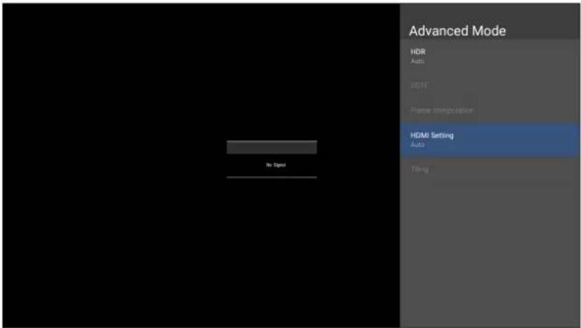 AutoSets the display to detect the range of the input signal automatically.FullSets the color range from 0~255.LimitedSets the color range from 15~255. AutoSets the display to detect the range of the input signal automatically.FullSets the color range from 0~255.LimitedSets the color range from 15~255. |
Speaker

flowchart
graph LR
    A["Color Mode"] --> B["Search Gear Icon"]
    C["Display Mode"] --> D["Search Gear Icon"]
    E["Advanced Mode"] --> F["Search Gear Icon"]
    G["Speaker"] --> H["Search Gear Icon"]
    I["PIP/PBP Mode"] --> J["Search Gear Icon"]
    K["Information"] --> L["Search Gear Icon"]
- Press MENU on the remote control to display the OSD Menu.
- Then press OK or use ▼/▲/◄/► on the remote control to select the Speaker menu.
- Press ▼/▲ to select the menu option. Then press OK to display its sub-menu, or press ◀/▶ to adjust/select the setting.
NOTE: Some sub-menu options may have another sub-menu layer.
| Menu Option Description | |
| Audio Mode | Speaker Audio Mode User 120Hz 0 500Hz 0 1.5kHz 0 5kHz 0 10kHz 0 Reset Audio Volume 13 Mute |
| Music Vibrant treble and stronger bass. Movie Enhance the sense of space. User Customize the audio equalizer. | |
| Reset | Return theSpeakersettings to their default values. |
| Audio Volume | Adjust the volume level. |
| Mute | Toggle On to turn off the speaker. |
PIP/PBP Mode

flowchart
graph LR
    A["Color Mode"] --> B["Display Mode"]
    B --> C["Advanced Mode"]
    C --> D["Speaker"]
    D --> E["PIP/PBP Mode"]
    E --> F["Information"]
- Press MENU on the remote control to display the OSD Menu.
- Then press OK or use ▼/▲/◄/► on the remote control to select the PIP/PBP Mode menu.
- Press ▼/▲ to select the menu option. Then press OK to display its sub-menu, or press ◀/▶ to adjust/select the setting.
NOTE: Some sub-menu options may have another sub-menu layer.
| Menu Option Description | |
| PIP/PBP Setup | |
| Off Disable the PIP/PBP feature. | |
Menu Option Description
PIP/PBP Setup
PIP
Split the screen into two parts, a main window and an inset window. User can specify the input source for each screen.

text_image
PFP/PGP Setup OFF Start user PFP user PGP Select RPG Player PGP Select RPG Player No Start PFP make set Setup Sub picture on top left Sub picture on top right Sub picture on bottom... Sub picture on bottom... In Start PFP make set Setup Mint Win HCM 1 Sub Win HCM 2 ENTER In Start Sub Win Main BoxMenu Option Description
PIP/PBP Setup
PBP
Display up to four (4) windows on screen at the same time.

text_image
PSF music selected Setup Windows x 2 1 top and 1 bottom Windows x 3 1 top and 2 bottom Windows x 3 2 top and 3 bottom Windows x 2 1 top and 2 bottom Windows x 3 2 top and 3 bottom Windows x 4 1 top and 3 bottom PSF music selected Setup WINS1 WINS2 WINS3 WINS4 WINS5 ENTER WIN1 WIN2 WIN3 WIN4Information

flowchart
graph LR
    A["Color Mode"] --> B["Search Gear Icon"]
    C["Display Mode"] --> D["Search Gear Icon"]
    E["Advanced Mode"] --> F["Search Gear Icon"]
    G["Speaker"] --> H["Search Gear Icon"]
    I["PIP/PBP Mode"] --> J["Search Gear Icon"]
    K["Information"] --> L["Search Gear Icon"]
- Press MENU on the remote control to display the OSD Menu.
- Then press OK or use ▼/▲/◄/► on the remote control to select the Information menu.
- Press ▼/▲ to select the menu option. Then press OK to display its sub-menu.
| Menu Option Description | |
| Information | View Input Source, Resolution, and HDR information. |
| Information Source Figure 1 Resolution HDR Action | |
Embedded Applications
ViewBoard Cast
Working with ViewBoard® Cast software, the vCastReceiver app, will allow the LED display to receive vCastSender screen sharing (Windows/Mac/Chrome) and mobile (iOS/Android) users' screens, photos, videos, annotations, and camera(s).

text_image
ViewBoard® Cast Connect & Collaborate Room Network: VSaccess Device Name: Cast-1343 Please open the vCastSender app to enter the password 9 E L S 3 N ① Connect to the Room Network ② Download and open vCastSender app VSaccess Visit below http://172.21.8.128:8000 Laptop Mobile Support iOS device AirPlayNetwork Information
- ViewBoard® Cast software, laptops, and mobile devices can be connected to the same subnet and across the subnet as long as it can communicate between the two.
- Connected devices will show up under "Device List" on the same subnet connection.
- If the device does not show up under "Device List", users will need to key-in the on-screen PIN-code.
ViewBoard Cast is a wireless peer to peer data communication, therefore the following port settings are required:
Ports:
• CP: 56789, 25123, 8121, and 8000
• UDP: 48689 and 25123
Port and DNS activation:
- Port: 8001
• DNS: h1.ee-share.com
Cast Sender from Windows-based Devices, Macbook, and Chrome devices.

text_image
ViewBoard® Cast Connect & Collaborate Room Network: VSaccess Device Name: Cast-1343 Please open the vCastSender app to enter the password LULLUR ① Connect to the Room Network ② Download and open vCastSender app VSSaccess Visit below http://172.21.8.128:8000 Laptop Mobile Support iOS device AirPlayMac, Windows, Chrome Devices:
- Make sure your device is connected to the same network as the display.
- Open a web browser and enter the address that is shown on the display to download the application.
- Launch the application and click the connect icon next to the Device Name.

text_image
vCastSender Device List Cast-1343 172.21.8.128 Cast-5551 172.21.10.186 Cast-2256 172.21.8.103 Cast-2745 172.21.10.71 ViewSonic PJ-65... 172.21.10.55 Joe Yang-T480s 172.21.8.128 VSaccessNOTE: If the device is not listed, click Connect with PIN-Code and input the pin-code displayed on the display.
Cast Sender from Mobile Devices: iOS-based (iPhone, iPad) and Android OS based phone/tablet.

text_image
ViewBoard® Cast Connect & Collaborate Room Network: VSaccess Device Name: Cast-1343 Please open the vCastSender app to enter the password IULVK7 ① Connect to the Room Network ② Download and op VSaccess Visit below http://172.21.8.128:1 Laptop Mobile AirPlay Support iOS deviceAndroid/iOS:
- Make sure your device is connected to the same network as the display.
- Scan the QR Code that is shown on the display to download the client application directly from the server, or download from the Google Play Store or the Apple Store.
- Launch the application and select the correct Device Name and input the pin to connect. You can also directly input the pin-code displayed on the display to connect.
Apple AirPlay®:
- Make sure your device is connected to the same network as the display.
- Directly open AirPlay and select the Device Name to connect.
- Another "AirPlay Password" will be generated on-screen for the connection.

text_image
ViewBoard® Cast Connect & Collaborate Please open the vCastSender app to enter the password Room Network: VSaccess Device Name: Cast-1343 AirPlay Password 842824 L R 7 J Tap here for first useCast Out from a Mobile Device that Supports Annotation

text_image
ViewBoard® Cast Connect & Collaborat Room Network: VSaccess Device Name: Cast-1343 DCIM 14 Screenshots 9 Camera 325 LINE 20 OGQ 1 LINE 5 Tap here fo enter the password SV| Item Description | ||
 | Toggle Hide or display the toolbar. | |
 | Home Return to the Home interface. | |
 | Return Return to the previous operation interface. | |
 | Folder View or open the mobile device's internal file. | |
 | Screen sharing Share the screen.NOTE: Android 5.0 and above supported. | |
 | Touch Change to touch mode. | |
 | Pen Make annotations, and change the color and thickness. | |
 | Clear Clear everything on the screen. | |
 | Camera Use the camera and send the image to the viewsBoard. | |
Browser
Web browser for surfing the Internet.

text_image
about:blank ← → C about:blankvSweeper
Remove unnecessary data and unwanted files.

text_image
Click to Sweep One click to clear memory and unwanted files Welcome to vSweeperAdvanced Settings can also be customized to the user's needs.

text_image
Main Preference Clear all Auto clear all junk files when the app starts Exit after clearing Exit after the clear button is clicked and the clean up has completed Auto Clear Auto clear interval Automatically clear all caches Auto clear on boot Automatically clear caches on system startup Auto Clear Interval No auto clear 1 day 1 hour 2 days 3 hours 1 week 6 hours 12 hours Advanced SettingsWPS Office
Create, edit, and view Documents, Memos, Presentations, and Spreadsheets.

text_image
WPS Office Recent Starred Open All Documents Pad Dropbox My Documents Download
text_image
New Spreadsheet New Presentation New Memo New DocumentAppendix
Specifications
| Item Category Specifications | ||
| Model LDP163-181 | ||
| LED Screen | Type Direct View LED Display | |
| Size 163" | ||
| Active Size | 141.73" (H) x 79.72" (V)3,600 mm (H) x 2,025 mm(V) | |
| Pitch Size 1.875 mm | ||
| Resolution FHD, 1920 x 1080 | ||
| Refresh Frequency 4440Hz | ||
| Contrast Ratio 6000:1 (Typical) | ||
| Brightness 100-600 cd/m2 (8 levels of adjustments) | ||
| LED Lifespan 100,000 hours | ||
| Input Signal | 5 x HDMI (1920 x 1080 @ 60Hz, HDCP 2.2)1 x LAN (RJ45)3 x USB Type A (2.0)1 x USB Type C | |
| Output Signal | 2 x HDMI (1080p @ 60Hz)1 x Audio Out (3.5 mm)3 x USB Type A (Power)[5V/1.5A] | |
| Speaker Output | 20W x 2 Harman-Kardon | |
| RS-232 | RS-232 Serial Control | |
| Power Voltage | 100-120V/30A ~ 50/60Hz220-240V/15A ~ 50Hz(vary by country) | |
| Operating Conditions | Temperature | 32°F to 104°F (0°C to 40°C) |
| Humidity | 20%~80% non-condensing | |
| Altitude | ≤ 6,562 ft (2,000 m) | |
| Storage Conditions | Temperature | -4°F to 140°F (-20°C to 60°C) |
| Humidity | 10%~90% non-condensing | |
| Altitude | ≤ 6,562 ft (2,000 m) | |
| Physical Dimensions (W x H x D) | w/o Wall Mount | 142.13" x 84.45" x 0.98"(3,610 x 2,145 x 25 mm) |
| w/ Wall Mount | 142.13" x 84.45" x 2.24"(3,610 x 2,145 x 57 mm) | |
| Weight | Physical | 375 lbs. (170 kg) |
| Power Consumption | On | 1,400W (Normal)2,200W (Max) |
| Sleep | < 0.5W | |
| Off | < 0W | |
NOTE: Product specifications are subject to change without notice.
LED Display Stuck Pixel Definition

natural_image
Grid pattern with a single green square in the center (no text or symbols)| Item Acceptance Criteria | |
| Stuck Pixel(whole display) | ≤ 60 stuck pixels |
| Stuck Pixel(as marked in green) | ≤ 18 stuck pixels |
| Stuck Pixel(Single Module) | ≤ 6 stuck pixels |
Timing Chart HDMI (PC)
| Resolution Refresh Rate (Hz) | |
| 640 x 480 60, 72, 75 | |
| 720 x 400 70, 85 | |
| 800 x 600 56, 60, 72, 75 | |
| 832 x 624 75 | |
| 1024 x 768 60, 70, 75 | |
| 1152 x 864 60, 70, 75 | |
| 1152 x 870 75 | |
| 1280 x 720 60 | |
| 1280 x 960 60 | |
| 1280 x 1024 60, 75 | |
| 1360 x 768 85 | |
| 1440 x 900 60 | |
| 1680 x 1050 60 | |
| 1600 x 1200 60, 70, 75 | |
| 1920 x 1080 60 | |
| 1920 x 1200 60 | |
| 3840 x 2160 30, 60 | |
HDMI (Video)
| Video Resolution Refresh Rate (Hz) | ||
| 480i | 720 x 480 60 | |
| 1440 x 480 60 | ||
| 576i | 720 x 576 50 | |
| 1440 x 576 50 | ||
| 480p | 720 x 480 60 | |
| 576p | 720 x 576 50 | |
| 1440 x 576 50 | ||
| 720p | 1280 x 720 60 | |
| 1080i | 1920 x 1080 50, 60 | |
| 1080p | 1920 x 1080 24, 25, | 30, 50, 60 |
| 2160p | 3840 x 2160 30, 60 | |
NOTE:
- The computer text quality is optimal in HD 1080 mode (1920 x 1080, 60Hz).
- Your computer display screen might appear different depending on the manufacturer and your operating system.
- Consult your computer's instructional manual on how to connect to an external display.
- If a vertical and horizontal frequency-select mode exists, select 60Hz (vertical) and 67.5KHz(horizontal). In some cases, abnormal signals (such as stripes) might appear on the screen when the computer power is turned off (or if the computer is disconnected). If this is the case, press the [INPUT SOURCE] button to enter the video mode and supply an active signal.
- The display timings conform to VESA and CTA standards.
- For 4:3 content, the screen will display them in the center of the screen and maintain a 4:3 aspect ratio.
- The optimal vertical frequency for each mode is 60Hz.
Supported Media Formats
Multimedia Codec Formats
| Type File Type Codec Ability | |||
| Photo | PNG | Max Resolution: 8000 × 8000Min Resolution : 4 x 4 | |
| JPEG/JPG | Max Resolution: 8000 × 8000Min Resolution : 4 x 41 | ||
| Video | .3gp | H.263 | Max Resolution: 1920 x 1080 30Audio: AMR_NB |
| MPEG-4 | Max Resolution: 1920 x 1080 30Audio: AMR_NB | ||
| .avi | MPEG-2/4 | Max Resolution: 1920 x 1080 30Audio: MPEG_Audio_Layer3 | |
| MJPEG | Max Resolution: 1920 x 1080 30Audio: MPEG_Audio_Layer3 | ||
| .flv H.264 | Max Resolution: 1920 x 1080 30Audio: AAC 2.0 | ||
| .mkv | H.264 | Max Resolution: 1920 x 1080 30Audio: AAC 2.0 | |
| H.265 | Max Resolution: 1920 x 1080 30Audio: AAC 2.0 | ||
| .mp4 | H.264 | Max Resolution: 3840 x 2160 30Audio: MPEG_Audio_Layer3 | |
| H.265 | Max Resolution: 3840 x 2160 30Audio: MPEG_Audio_Layer3 | ||
| MPEG-4 | Max Resolution: 1920 x 1080 30Audio: MPEG_Audio_Layer3 | ||
| .vob MPEG-2 | Max Resolution: 1920 x 1080 30Audio: PCM | ||
| .mpg/.mpeg MPEG-2 | Max Resolution: 1920 x 1080 30Audio: MPEG_Audio_Layer3 | ||
| Audio | .aac GAAC | Sample Rate: 8K~96KHzBit Rate: 24K~576Kbps | |
| .ape Monkey's Audio | Sample Rate: max 48KHzBit Rate: max 1411Kbps | ||
| .flac FLAC | Sample Rate: max 192KHzBit Rate: max 1411Kbps | ||
| .m4a ALAC | Sample Rate: 8K~96KHzBit Rate: 24K~576Kbps | ||
| .mp3 MPEG1/2 layer 3 | Sample Rate: 8K~48KHzBit Rate: 32K~320Kbps | ||
| .ogg Vorbis | Sample Rate: 8K~48KHzBit Rate: max 256Kbps | ||
| .wav LPCM | Sample Rate: 8K~192KHzBit Rate: max 320Kbps | ||
Troubleshooting
| Problem or Issue Possible Solutions | |
| Remote Control is not working | 1. Check whether something is obstructing the display's remote control receiver.2. Check whether the battery polarities in the remote control are installed correctly.3. Check whether the batteries need to be replaced. |
| The unit turns off unexpectedly | 1. Check whether Sleep mode is enabled.2. Check if there is a power outage in your area.3. Turn on the display, provide an active signal, and see if the problem is with the signal or external control system. |
| The power indicator is off, and there is no response | 1. Ensure the power cable is connected and not loose.2. Check that the power outlet is functioning properly and meets the required electrical requirement. |
| The display does not recognize the USB storage device | 1. Ensure the drive is either formatted for FAT32 or NTFS.2. If the USB storage device needs external power, connect its power adapter to an electrical outlet. |
Video Not Working Properly
| Problem or Issue Possible Solutions | |
| No picture/No sound | 1. Check the Power status.2. Check the signal cable.3. Use the remote control to ensure the input source setting is the same as the connected device. |
| Picture is unclear or cuts in and out | 1. Check the signal cable.2. Check if other electronics or different signal types are interrupting the signal.3. An optional active video cable or optional video extender is required for a long distance source. |
| Poor picture | 1. Adjust chroma and/or brightness settings in the menu.2. Check the signal cable.3. Use the display's native resolution for the source. |
Audio Not Working Properly
| Problem or Issue Possible Solutions | |
| No sound | 1. Press the Mute/Unmute button.2. Adjust the volume.3. Check the audio cable connection (if used).4. If using a computer digital video with embedded audio, ensure the computer speakers are set to external speakers. |
| One speaker only | 1. Adjust the sound balance in the menu.2. Check the left and right sound control panel settings of the computer or media player source.3. Check the audio cable connection (if used).4. Ensure the content has two audio channels and not mono. |
Maintenance
General Precautions
- The LED lights used in the modules are susceptible to ESD (Electrostatic discharge). To prevent damage to the LED lights, do not touch them with bare hands or with conductive materials when handling.
- It is recommended to regularly inspect all installed components.
- Do not bring objects close to the ventilation holes of the display. Burns or personal injuries may occur if any body parts are brought too close.
- Be sure to power off and disconnect all cables before moving the display. Moving the display with its cables attached may damage the cables and thus cause fire or electric shock.
- Power off and disconnect the power plug from the wall outlet as a safety precaution before performing any type of cleaning or maintenance.
Initial Operation
- If a new screen has been stowed for less than three (3) months, it can be used at normal brightness during its first use.
- If a new screen has been stowed for more than three (3) months, the brightness should be set at 30% for its first use and allowed to operate for two (2) hours continuously. After two (2) hours of use, power off for 30 minutes. The new screen is now ready for normal brightness usage.
Front Panel Cleaning Instructions
- Use cool, compressed air to remove dust when the power is off. If the dust cannot be removed, the LED module should be replaced.
- Do not scratch and do not put pressure on the panel surface with fingers or any abrasive object.
- Do not use volatile substances such as sprays, solvents, or thinners.
Cabinet Cleaning Instructions
- Do not allow water or detergent to come into contact with the surface of the display. If water or moisture gets inside the unit, a system malfunction or electrical shock may occur.
- Do not scratch and do not put pressure on the cabinet with any abrasive objects of any kind.
- Do not use volatile substances such as sprays, solvents, or thinners on the cabinet.
- Do not place anything made from rubber or PVC near the cabinet for any extended periods of time.
Regular Use
- It is recommended to turn on the display at least once a month for more than eight (8) hours. During a wet and rainy season, it is recommended to turn on the display at least once a week.
- Avoid using full white, full red, full blue, or full green content for an extended period to avoid excessive power usage thus affecting the LED lifespan.
Vacuum Suction Tool


text_image
140 28.2 75.4
text_image
144.25 35 75.99 210 152
text_image
134 97.5 194 157.5Charging the Battery

text_image
Diagram showing a device connected to a plug and two socket outlets, with labeled components and directional arrows.Changing the Battery

text_image
Technical diagram of a device with labeled components and an inset showing a close-up of a device's internal structure.
text_image
Technical diagram of a hair dryer with labeled parts and red arrows indicating motion or assembly stepsLED Module Disassembly
1
②

natural_image
Line drawing of a cylindrical device with a red arrow pointing to the button (no text or symbols)
text_image
Technical diagram showing a mechanical device with a magnified inset highlighting a component detail with red arrows indicating direction.4
③

natural_image
Line drawing of a cylindrical device with a red arrow pointing to a button (no text or symbols)
natural_image
Technical diagram of a mechanical device with red directional arrows indicating movement or force (no text or symbols present)Overview

text_image
Technical diagram of a device with numbered parts labeled 1 to 8, showing internal components and directional arrows.| Number Item Description | ||
| 1 | Lanyard Ring | Lanyard attachment point. |
| 2 | Regulating Valve | Adjust the suction force level. Cover the valve for the strongest suction force. |
| 3 | LED Module Contact Silicone | Soft contact surface for LED module removal. |
| 4 | Power Display | Battery indicator. |
| 5 | Power Switch | Turn the device On/Off. |
| 6 | Start Button | Engage/Disengage the suction force. |
| 7 | Battery Removal Button | Press to remove the battery. |
| 8 | Charging Port | Port for battery charging. |
Specifications
| Item Description | |
| Model | LD-MK-001 |
| Suction Face Dimension | 5.27" x 7.64"(134 x 194 mm) |
| Available Module Size | 7.56" x 7.56" to 19.69" x 19.69"(192 x 192 to 500 x 500 mm) |
| Product Dimension | 5.98" x 5.51" x 8.27"(152 x 140 x 210 mm) |
| Weight | 2.58 lbs.(1.17 kg) |
| Working Duration | 17 minutes |
| Working Temperature | 37.4° to 131° F (3° to 55° C) |
RS-232 Protocol
This document describes the hardware interface and software protocols of RS-232 serial communication between the ViewSonic LED Display and computers or control systems.
RS-232 Hardware Specification
ViewSonic RS-232 serial port on the lower left side:
- Connector type: DB 9-Pin Female
- Use of straight-through parallel cable for connection
- Pin Assignment:

text_image
Female DB 9-Pin 5 4 3 2 1 9 8 7 6| Signal Remark | |
| 1 NC | |
| 2 TXD Output from Display | |
| 3 RXD Input to Display | |
| 4 NC | |
| 5 GND GND | |
| 6 NC | |
| 7 NC | |
| 8 NC | |
| 9 NC | |
| frame GND | |
RS-232 Communication Setting
- Baud Rate Select: 115200bps (fixed)
- Data bits: 8 bits (fixed)
- Parity: None (fixed)
- Stop Bits: 1(fixed)
Command Table
| Function Command Code (Hex) HEX Data Range | |||
| Power On 21 38 30 31 73 21 30 30 31 0D | |||
| Power Off (Standby) 21 38 30 31 73 21 30 30 30 0D | |||
| Get-Power Status 6C 38 30 31 67 6C 30 30 30 0D | |||
| Input Select: HDMI 1 22 38 30 31 73 22 30 30 34 0D | |||
| Input Select: HDMI 2 22 38 30 31 73 22 30 31 34 0D | |||
| Get-Input Select 6A 38 30 31 67 6A 30 30 30 0D | |||
| Input Select: Home 22 38 30 31 73 22 30 30 41 0D | |||
| Brightness: Down (-1) 24 38 30 31 73 24 39 30 30 0D | |||
| Brightness: Up (+1) 24 38 30 31 73 24 39 30 31 0D | |||
| Volume: Down (-1) 35 38 30 31 73 35 39 30 30 0D | |||
| Volume: Up (+1) 35 38 30 31 73 35 39 30 31 0D | |||
| Get-Volume | 66 38 30 31 67 | 66 30 30 30 0D | |
| Mute: OFF | 36 38 30 31 73 | 36 30 30 30 0D | |
| Mute: ON (mute) | 36 38 30 31 73 | 36 30 30 31 0D | |
| Get-Mute | 67 38 30 31 67 | 67 30 30 30 0D | |
| Number (0~9) | 40 | 38 30 31 73 40 30 30 3x 0D | x = 0~9 |
| Key Pad: UP | 41 38 30 31 73 | 41 30 30 30 0D | |
| Key Pad: DOWN | 41 38 30 31 73 | 41 30 30 31 0D | |
| Key Pad: LEFT | 41 38 30 31 73 | 41 30 30 32 0D | |
| Key Pad: RIGHT | 41 38 30 31 73 | 41 30 30 33 0D | |
| Key Pad: ENTER | 41 38 30 31 73 | 41 30 30 34 0D | |
| Key Pad: INPUT | 41 38 30 31 73 | 41 30 30 35 0D | |
| Key Pad: MENU | 41 38 30 31 73 | 41 30 30 36 0D | |
| Key Pad: EXIT | 41 38 30 31 73 | 41 30 30 37 0D | |
| Get-Operational Hours 31 38 30 31 67 31 30 30 30 0D | |||
Regulatory and Service Information
Compliance Information
This section addresses all connected requirements and statements regarding regulations. Confirmed corresponding applications shall refer to nameplate labels and relevant markings on the unit.
FCC Compliance Statement
This device complies with part 15 of FCC Rules. Operation is subject to the following two conditions: (1) this device may not cause harmful interference, and (2) this device must accept any interference received, including interference that may cause undesired operation. This equipment has been tested and found to comply with the limits for a Class B digital device, pursuant to part 15 of the FCC Rules.
These limits are designed to provide reasonable protection against harmful interference in a residential installation. This equipment generates, uses, and can radiate radio frequency energy, and if not installed and used in accordance with the instructions, may cause harmful interference to radio communications. However, there is no guarantee that interference will not occur in a particular installation. If this equipment does cause harmful interference to radio or television reception, which can be determined by turning the equipment off and on, the user is encouraged to try to correct the interference by one or more of the following measures:
- Reorient or relocate the receiving antenna.
- Increase the separation between the equipment and receiver.
- Connect the equipment into an outlet on a circuit different from that to which the receiver is connected.
- Consult the dealer or an experienced radio/TV technician for help.
The antenna(s) used for this transmitter must not be collocated or operating in conjunction with any other antenna or transmitter.
The device was tested and complies to measurement standards and procedures specified in FCC CFR Tile 47 Part 15 Subpart C.
FCC Radiation Exposure Statement
This equipment complies with FCC radiation exposure limits set forth for an uncontrolled environment. End users must follow the specific operating instructions for satisfying RF exposure compliance.
This transmitter must not be co-located or operating in conjunction with any other antenna or transmitter. This equipment should be installed and operated with a minimum distance of 20 centimeters between the radiator and your body.
The users manual or instruction manual for an intentional or unintentional radiator shall caution the user that changes or modifications not expressly approved by the party responsible for compliance could void the user's authority to operate the equipment.
Warning: You are cautioned that changes or modifications not expressly approved by the party responsible for compliance could void your authority to operate the equipment.
IC Warning Statement
This device complies with Industry Canada license- exempt RSS standard(s). Operation is subject to the following two conditions: (1) this device may not cause interference, and (2) this device must accept any interference, including interference that may cause undesired operation of the device.
For product available in the USA/Canada market, only channel 1\~11 can be operated. Selection of other channels is not possible.
This equipment complied with IC RSS-102 radiation exposure limits set forth for an uncontrolled environment. This equipment should be installed and operated with minimum distance 20cm between the radiator & your body. The device for the band 5150-5825 MHz is only for indoor usage to reduce potential for harmful interference to co-channel mobile satellite systems.
CE Conformity for European Countries

The device complies with the EMC Directive 2014/30/EU and Low Voltage Directive 2014/35/EU.
The following information is only for EU-member states:
The mark shown to the right is in compliance with the Waste Electrical and Electronic Equipment Directive 2012/19/EU (WEEE). The mark indicates the requirement NOT to dispose of the equipment as unsorted municipal waste, but use the return and collection systems according to local law.

Declaration of RoHS2 Compliance
This product has been designed and manufactured in compliance with Directive 2011/65/EU of the European Parliament and the Council on restriction of the use of certain hazardous substances in electrical and electronic equipment (RoHS2 Directive) and is deemed to comply with the maximum concentration values issued by the European Technical Adaptation Committee (TAC) as shown below:
| Substance | Proposed Maximum Concentration | Actual Concentration |
| Lead (Pb) 0.1% < 0.1% | ||
| Mercury (Hg) 0.1% < 0.1% | ||
| Cadmium (Cd) 0.01% < 0.01% | ||
| Hexavalent Chromium (Cr6+) 0.1% < 0.1% | ||
| Polybrominated biphenyls (PBB) 0.1% < 0.1% | ||
| Polybrominated diphenyl ethers (PBDE) | 0.1% < 0.1% | |
| Bis (2-ethylhexyl) phthalate (DEHP) | 0.1% < 0.1% | |
| Butyl benzyl phthalate (BBP) 0.1% < 0.1% | ||
| Dibutyl phthalate (DBP) 0.1% < 0.1% | ||
| Diisobutyl phthalate (DIBP) 0.1% < 0.1% |
Certain components of products as stated above are exempted under the Annex III of the RoHS2 Directives as noted below:
• Copper alloy containing up to 4% lead by weight.
- Lead in high melting temperature type solders (i.e. lead-based alloys containing 85% by weight or more lead).
- Electrical and electronic components containing lead in a glass or ceramic other than dielectric ceramic in capacitors, e.g. piezoelectronic devices, or in a glass or ceramic matrix compound.
- Lead in dielectric ceramic in capacitors for a rated voltage of 125V AC or 250V DC or higher.
European Union Regulatory Conformance
The equipment complies with the RF Exposure Requirement 2014/53/EU, Council Recommendation of 16 April 2014 on the limitation of exposure of the general public to electromagnetic fields (0-300 GHz). This equipment meets the following conformance standards: EN301489-1, EN301489-17, EN62368-1, EN300328.
We, hereby, declare that this Wi-Fi radio is in compliance with the essential requirements and other relevant provisions of Directive 2014/53/EU.
Indian Restriction of Hazardous Substances
Restriction on Hazardous Substances statement (India). This product complies with the “India E-waste Rule 2011” and prohibits use of lead, mercury, hexavalent chromium, polybrominated biphenyls or polybrominated diphenyl ethers in concentrations exceeding 0.1 weight % and 0.01 weight % for cadmium, except for the exemptions set in Schedule 2 of the Rule.
Product Disposal at End of Product Life
ViewSonic ^® respects the environment and is committed to working and living green. Thank you for being part of Smarter, Greener Computing. Please visit the ViewSonic ^® website to learn more.
USA & Canada:
https://www.viewsonic.com/us/go-green-with-viewsonic
Europe:
https://www.viewsonic.com/eu/go-green-with-viewsonic
Taiwan:
Copyright© ViewSonic® Corporation, 2023. All rights reserved.
Macintosh and Power Macintosh are registered trademarks of Apple Inc.
Microsoft, Windows, and the Windows logo are registered trademarks of Microsoft Corporation in the United States and other countries.
ViewSonic ^® , the three birds logo, OnView, ViewMatch, and ViewMeter are registered trademarks of ViewSonic ^® Corporation.
VESA is a registered trademark of the Video Electronics Standards Association. DPMS, DisplayPort, and DDC are trademarks of VESA.
CTA is a registered trademark of the Consumer Technology Association Standards.
Disclaimer: ViewSonic® Corporation shall not be liable for technical or editorial errors or omissions contained herein; nor for incidental or consequential damages resulting from furnishing this material, or the performance or use of this product.
In the interest of continuing product improvement, ViewSonic® Corporation reserves the right to change product specifications without notice. Information in this document may change without notice.
No part of this document may be copied, reproduced, or transmitted by any means, for any purpose without prior written permission from ViewSonic® Corporation.
Customer Service
For technical support or product service, see the table below or contact your reseller.
NOTE: You will need the product's serial number.
| Country/ Region | Website | Country/ Region | Website |
| Asia Pacific & Africa | |||
| Australia | www.viewsonic.com/au/ | Bangladesh | www.viewsonic.com/bd/ |
| 中国 (China) | www.viewsonic.com.cn | 香港(繁體中文) | www.viewsonic.com/hk/ |
| Hong Kong (English) | www.viewsonic.com/hk-en/ | India | www.viewsonic.com/in/ |
| Indonesia | www.viewsonic.com/id/ | Israel | www.viewsonic.com/il/ |
| 日本 (Japan) | www.viewsonic.com/jp/ | Korea | www.viewsonic.com/kr/ |
| Malaysia | www.viewsonic.com/my/ | Middle East | www.viewsonic.com/me/ |
| Myanmar | www.viewsonic.com/mm/ | Nepal | www.viewsonic.com/np/ |
| New Zealand | www.viewsonic.com/nz/ | Pakistan | www.viewsonic.com/pk/ |
| Philippines | www.viewsonic.com/ph/ | Singapore | www.viewsonic.com/sg/ |
| 臺灣 (Taiwan) | www.viewsonic.com/tw/ | ประเทศไทย | www.viewsonic.com/th/ |
| Việt Nam | www.viewsonic.com/vn/ | South Africa & Mauritius | www.viewsonic.com/za/ |
| Americas | |||
| United States | www.viewsonic.com/us | Canada | www.viewsonic.com/us |
| Latin America | www.viewsonic.com/la | ||
| Europe | |||
| Europe | www.viewsonic.com/eu/ | France | www.viewsonic.com/fr/ |
| Deutschland | www.viewsonic.com/de/ | Қазақстан | www.viewsonic.com/kz/ |
| Россия | www.viewsonic.com/ru/ | España | www.viewsonic.com/es/ |
| Türkiye | www.viewsonic.com/tr/ | Україна | www.viewsonic.com/ua/ |
| United Kingdom | www.viewsonic.com/uk/ | ||
Limited Warranty
ViewSonic® Commercial Display
What the warranty covers:
ViewSonic® warrants its products to be free from defects in material and workmanship during the warranty period. If a product proves to be defective in material or workmanship during the warranty period, ViewSonic® will, at its sole option, and as your sole remedy, repair or replace the product with a similar product. Replacement Product or parts may include remanufactured or refurbished parts or components. The repair or replacement unit or parts or components will be covered by the balance of the time remaining on the customer's original limited warranty and the warranty period will not be extended. ViewSonic® provides no warranty for any third-party software whether included with the product or installed by the customer, installation of any unauthorized hardware parts or components (e.g. Projector Lamps). (Please refer to: "What the warranty excludes and does not cover" section).
Who the warranty protects:
This warranty is valid only for the first consumer purchaser.
What the warranty excludes and does not cover:
- Any product on which the serial number has been defaced, modified, or removed.
- Damage, deterioration, or malfunction resulting from:
» Accident, misuse, neglect, fire, water, lightning, or other acts of nature, unauthorized product modification, or failure to follow instructions supplied with the product.
» Repair or attempted repair by anyone not authorized by ViewSonic®.
» Damage to or loss of any programs, data, or removable storage media.
» Normal wear and tear.
» Removal or installation of the product.
- Software or data loss occurring during repair or replacement.
- Any damage of the product due to shipment.
- Causes external to the product, such as electric power fluctuations or failure.
- Use of supplies or parts not meeting ViewSonic's specifications.
-
Failure of owner to perform periodic product maintenance as stated in the User Guide.
-
Any other cause which does not relate to a product defect.
- Damage caused by static (non-moving) images displayed for lengthy periods of time (also referred to as image burn-in).
- Software - Any third-party software included with the product or installed by the customer.
- Hardware/Accessories/Parts/Components – Installation of any unauthorized hardware, accessories, consumable parts or components (e.g. Projector Lamps).
- Damage to, or abuse of, the coating on the surface of the display through inappropriate cleaning as described in the product User Guide.
- Removal, installation, and set-up service charges, including wall-mounting of the product.
How to get service:
- For information about receiving service under warranty, contact ViewSonic® Customer Support (Please refer to the “Customer Service” page). You will need to provide your product’s serial number.
- To obtain warranty service, you will be required to provide: (a) the original dated sales slip, (b) your name, (c) your address, (d) a description of the problem, and (e) the serial number of the product.
- Take or ship the product, freight prepaid, in the original container to an authorized ViewSonic® service center or ViewSonic®.
- For additional information or the name of the nearest ViewSonic® service center, contact ViewSonic®.
Limitation of implied warranties:
There are no warranties, express or implied, which extend beyond the description contained herein including the implied warranty of merchantability and fitness for a particular purpose.
Exclusion of damages:
ViewSonic's liability is limited to the cost of repair or replacement of the product. ViewSonic® shall not be liable for:
- Damage to other property caused by any defects in the product, damages based upon inconvenience, loss of use of the product, loss of time, loss of profits, loss of business opportunity, loss of goodwill, interference with business relationships, or other commercial loss, even if advised of the possibility of such damages.
- Any other damages, whether incidental, consequential or otherwise.
- Any claim against the customer by any other party.
- Repair or attempted repair by anyone not authorized by ViewSonic®.
Effect of state law:
This warranty gives you specific legal rights, and you may also have other rights which vary from state to state. Some states do not allow limitations on implied warranties and/or do not allow the exclusion of incidental or consequential damages, so the above limitations and exclusions may not apply to you.
Sales outside the U.S.A. and Canada:
For warranty information and service on ViewSonic® products sold outside of the U.S.A. and Canada, contact ViewSonic® or your local ViewSonic® dealer.
The warranty period for this product in mainland China (Hong Kong, Macao, and Taiwan Excluded) is subject to the terms and conditions of the Maintenance Guarantee Card.
For users in Europe and Russia, full details of warranty provided can be found at: http://www.viewsonic.com/eu/ under "Support/Warranty Information".
Mexico Limited Warranty
ViewSonic® Commercial Display
What the warranty covers:
ViewSonic® warrants its products to be free from defects in material and workmanship, under normal use, during the warranty period. If a product proves to be defective in material or workmanship during the warranty period, ViewSonic® will, at its sole option, repair or replace the product with a like product. Replacement product or parts may include remanufactured or refurbished parts or components & accessories.
Who the warranty protects:
This warranty is valid only for the first consumer purchaser.
What the warranty excludes and does not cover:
- Any product on which the serial number has been defaced, modified or removed.
- Damage, deterioration, or malfunction resulting from:
» Accident, misuse, neglect, fire, water, lightning, or other acts of nature, unauthorized product modification, unauthorized attempted repair, or failure to follow instructions supplied with the product.
» Causes external to the product, such as electrical power fluctuations or failure.
» Use of supplies or parts not meeting ViewSonic®’s specifications.
» Normal wear and tear.
» Any other cause which does not relate to a product defect.
- Any product exhibiting a condition commonly known as “image burn-in” which results when a static image is displayed on the product for an extended period of time.
- Removal, installation, insurance, and set-up service charges.
How to get service:
For information about receiving service under warranty, contact ViewSonic® Customer Support (Please refer to the attached “Customer Service” page). You will need to provide your product’s serial number, so please record the product information in the space provided below on your purchase for your future use. Please retain your receipt of proof of purchase to support your warranty claim.
For Your Records
Product Name: Model Number:
Document Number: Serial Number:
Purchase Date: Extended Warranty Purchase? (Y/N)
If so, what date does warranty expire?
- To obtain warranty service, you will be required to provide (a) the original dated sales slip, (b) your name, (c) your address, (d) a description of the problem, and (e) the serial number of the product.
- Take or ship the product, in the original container packaging, to an authorized ViewSonic® service center.
- Round trip transportation costs for in-warranty products will be paid by ViewSonic®.
Limitation of implied warranties:
There are no warranties, express or implied, which extend beyond the description contained herein including the implied warranty of merchantability and fitness for a particular purpose.
Exclusion of damages:
ViewSonic®'s liability is limited to the cost of repair or replacement of the product. ViewSonic® shall not be liable for:
- Damage to other property caused by any defects in the product, damages based upon inconvenience, loss of use of the product, loss of time, loss of profits, loss of business opportunity, loss of goodwill, interference with business relationships, or other commercial loss, even if advised of the possibility of such damages.
- Any other damages, whether incidental, consequential or otherwise.
- Any claim against the customer by any other party.
- Repair or attempted repair by anyone not authorized by ViewSonic®.
| Contact Information for Sales & Authorized Service (Centro Autorizado de Servicio) within Mexico: | |
| Name, address, of manufacturer and importers:México, Av. de la Palma #8 Piso 2 Despacho 203, Corporativo Interpalmas,Col. San Fernando Huixquilucan, Estado de MéxicoTel: (55) 3605-1099 http://www.viewsonic.com/la/soporte/index.htm | |
| NÚMERO GRATIS DE ASISTENCIA TÉCNICA PARA TODO MÉXICO: 001.866.823.2004 | |
| Hermosillo:Distribuciones y Servicios Computacionales SA de CV.Calle Juarez 284 local 2Col. Bugambilias C.P: 83140Tel: 01-66-22-14-9005E-Mail: disc2@hmo.megared.net.mx | Villahermosa:Compumantenimietnos Garantizados, S.A. de C.V.AV. GREGORIO MENDEZ #1504COL, FLORIDA C.P. 86040Tel: 01 (993) 3 52 00 47 / 3522074 / 3 52 20 09E-Mail: compumantenimientos@prodigy.net.mx |
| Puebla, Pue. (Matriz):RENTA Y DATOS, S.A. DE C.V. Domicilio:29 SUR 721 COL. LA PAZ72160 PUEBLA, PUE.Tel: 01(52).222.891.55.77 CON 10 LINEASE-Mail: datos@puebla.megared.net.mx | Veracruz, Ver.:CONEXION Y DESARROLLO, S.A DE C.V. Av.Americas # 419ENTRE PINZÓN Y ALVARADOFracc. Reforma C.P. 91919Tel: 01-22-91-00-31-67E-Mail: gacosta@qplus.com.mx |
| Chihuahua:Soluciones Globales en ComputaciónC. Magisterio # 3321 Col. MagisterialChihuahua, Chih.Tel: 4136954E-Mail: Cefeo@soluglobales.com | Cuernavaca:Compusupport de Cuernavaca SA de CVFrancisco Leyva # 178 Col. Miguel HidalgoC.P. 62040, Cuernavaca MorelosTel: 01 777 3180579 / 01 777 3124014E-Mail: aquevedo@compusupportcva.com |
| Distrito Federal:QPLUS, S.A. de C.V.Av. Coyoacán 931Col. Del Valle 03100, México, D.F.Tel: 01(52)55-50-00-27-35E-Mail : gacosta@qplus.com.mx | Guadalajara, Jal.:SERVICRECE, S.A. de C.V.Av. Niños Héroes # 2281Col. Arcos Sur, Sector Juárez44170, Guadalajara, JaliscoTel: 01(52)33-36-15-15-43E-Mail: mmiranda@servicrece.com |
| Guerrero Acapulco:GS Computación (Grupo Sesicomp)Progreso #6-A, Colo Centro39300 Acapulco, GuerreroTel: 744-48-32627 | Monterrey:Global Product ServicesMar Caribe # 1987, Esquina con Golfo PérsicoFracc. Bernardo Reyes, CP 64280Monterrey N.L. MéxicoTel: 8129-5103E-Mail: aydeem@gps1.com.mx |
| MERIDA:ELECTROSERAv Reforma No. 403Gx39 y 41Mérida, Yucatán, México CP97000Tel: (52) 999-925-1916E-Mail: rrrb@sureste.com | Oaxaca, Oax.:CENTRO DE DISTRIBUCION YSERVICIO, S.A. de C.V.Murguía # 708 P.A., Col. Centro, 68000, OaxacaTel: 01(52)95-15-15-22-22Fax: 01(52)95-15-13-67-00E-Mail. gpotai2001@hotmail.com |
| Tijuana:STDAv Ferrocarril Sonora #3780 L-CCol 20 de NoviembrTijuana, Mexico | FOR USA SUPPORT:ViewSonic® Corporation381 Brea Canyon Road, Walnut, CA. 91789 USATel: 800-688-6688E-Mail: http://www.viewsonic.com |

natural_image
Illustration of three colorful bird figurines with blue, purple, and yellow caps (no text or symbols)ViewSonic®