OLCB2X1U - Wall mount Chief - Free user manual and instructions
Find the device manual for free OLCB2X1U Chief in PDF.

User questions about OLCB2X1U Chief
0 question about this device. Answer the ones you know or ask your own.
Ask a new question about this device
Download the instructions for your Wall mount in PDF format for free! Find your manual OLCB2X1U - Chief and take your electronic device back in hand. On this page are published all the documents necessary for the use of your device. OLCB2X1U by Chief.
USER MANUAL OLCB2X1U Chief
INSTALLATION INSTRUCTIONS
natural_image
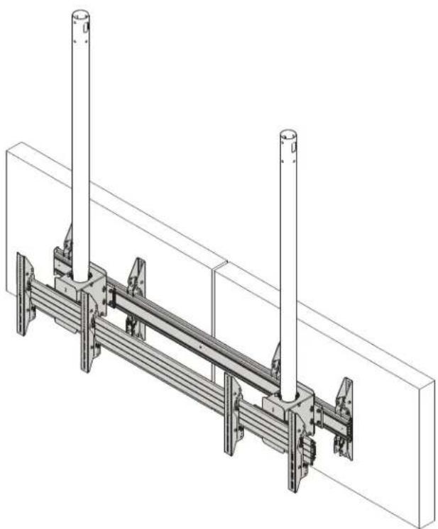
Technical line drawing of a mechanical assembly with two vertical posts and a horizontal beam (no text or symbols)Ceiling-Mounted Back-to-Back Outdoor Menu Boards
DISCLAIMER
Milestone AV Technologies and its affiliated corporations and subsidiaries (collectively "Milestone"), intend to make this manual accurate and complete. However, Milestone makes no claim that the information contained herein covers all details, conditions or variations, nor does it provide for every possible contingency in connection with the installation or use of this product. The information contained in this document is subject to change without notice or obligation of any kind. Milestone makes no representation of warranty, expressed or implied, regarding the information contained herein. Milestone assumes no responsibility for accuracy, completeness or sufficiency of the information contained in this document.
Chief® is a registered trademark of Milestone AV Technologies. All rights reserved.
DEFINITIONS
MOUNTING SYSTEM: A MOUNTING SYSTEM is the primary Chief product to which an accessory and/or component is attached.
ACCESSORY: AN ACCESSORY is the secondary Chief product which is attached to a primary Chief product, and may have a component attached or setting on it.
COMPONENT: A COMPONENT is an audiovisual item designed to be attached or resting on an accessory or mounting system such as a video camera, CPU, screen, display, projector, etc.

WARNING: A WARNING alerts you to the possibility of serious injury or death if you do not follow the instructions.

CAUTION: A CAUTION alerts you to the possibility of damage or destruction of equipment if you do not follow the corresponding instructions.

IMPORTANT SAFETY INSTRUCTIONS

WARNING: Failure to read, thoroughly understand, and follow all instructions can result in serious personal injury, damage to equipment, or voiding of factory warranty! It is the installer's responsibility to make sure all components are properly assembled and installed using the instructions provided.

WARNING: Failure to provide adequate structural strength for this component can result in serious personal injury or damage to equipment! It is the installer's responsibility to make sure the structure to which this component is attached can support five times the combined weight of all equipment. Reinforce the structure as required before installing the component.

WARNING: Exceeding the weight capacity can result in serious personal injury or damage to equipment! It is the installer's responsibility to make sure the combined weight of all components located within the mounting system of the
OLCB2X1U mounts does not exceed 500 lbs (226.8 kg) total or 125 lbs (56.7 kg) per display.
| 125 125 | |
| 125125 |
NOTE: "Moment" ratings have NOT been evaluated by UL.

WARNING: Exceeding the maximum moment can result in serious personal injury or damage to equipment! It is the installer's responsibility to make sure the mounting system does not exceed a moment of 2000 ft-lbs. See table below for specific column specifications.
| COLUMN MODEL | Weight capacity | Moment Length (IN) (ML) | Max Design Moment (FT-LBS) (MDM) |
| ODAC0203B | 300 lbs (136 kg) 23 | min - 36 max 2000 | |
| ODAC0304B | 300 lbs (136 kg) 33 | min - 48 max 2000 | |
| ODAC0405B | 300 lbs (136 kg) 45 | min - 60 max 2000 | |
| ODAC0506B | 300 lbs (136 kg) 57 | min - 72 max 2000 | |
| ODAC0708B | 300 lbs (136 kg) 81 | min - 96 max 2000 |

WARNING: Never operate this mounting system if it is damaged. Return the mounting system to a service center for examination and repair.

WARNING: Use this mounting system only for its intended use as described in these instructions. Do not use attachments not recommended by the manufacturer.

WARNING: Never operate this mounting system if it is damaged. Return the mounting system to a service center for examination and repair.

WARNING: Use this mounting system with other outdoor products only.

WARNING: Always use two people or a mechanical lifting device to safely lift and position equipment.
NOTE: The OLCB2X1U flat panel floor/ceiling mounts are intended to be used with UL Listed ODAC Series columns (not included): ODAC0203, ODAC0304, ODAC0405, ODAC0506, ODAC0708.
--SAVE THESE INSTRUCTIONS--
DIMENSIONS

text_image
2.16 [54.8] 1.77 [45.0] 5.71 [145.0] 5.27 [133.9] 72.00 [1828.8] 5.375 [136.5] 15.75 [400.0] MAX VERTICAL MOUNTING PATTERN 0.34 [8.6] HOLE FOR PADLOCK AND LOCKOUT SCREW 20° MAX FORWARD TILT 7.6" MAX BACK TILT LOCKOUTS AT: +7.6° +5° 0° -5° -10° -15° -20° MIN 39.07 - MAX 54.81 [992.3] - [1392.3] SPACING: COLUMNS SHOULD BE APPROXIMATELY CENTERED ON DISPLAY 8.14 [206.7] HEIGHT ADJUSTMENT ±1" 1.00 [25.4] 2.06 [52.4] 5.27 [133.8] 5.78 [146.8] 9.14 [232.1] APPROXIMATE WEIGHT: 76 LBS 14.26 [362.2] 16.75 [425.5] DIMENSIONS: INCHES [MILLIMETERS]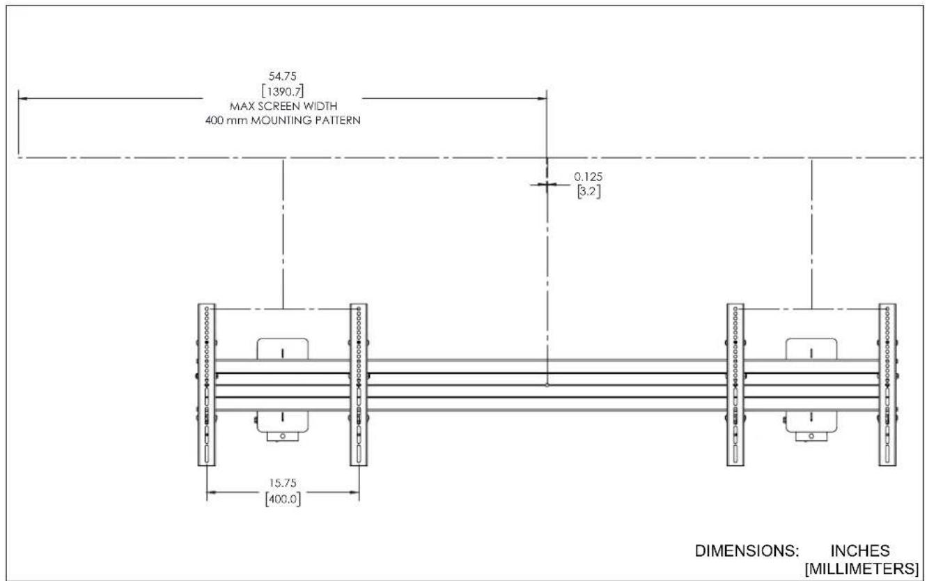
text_image
54.75 [1390.7] MAX SCREEN WIDTH 400 mm MOUNTING PATTERN 0.125 [3.2] 15.75 [400.0] DIMENSIONS: INCHES [MILLIMETERS]
text_image
46.88 [1190.7] MAX SCREEN WIDTH 600 mm MOUNTING PATTERN 0.125 [3.2] 23.62 [600.0]DIMENSIONS: INCHES [MILLIMETERS]

text_image
39.00 [990.7] MAX SCREEN WIDTH 800 mm MOUNTING PATTERN 0.125 [3.4] 31.50 [800.0]DIMENSIONS (cont'd)
LEGEND
 | Tighten Fastener |  | Pencil Mark |
| Apretar elemento de fijación | Marcar con lápiz | ||
| Befestigungsteil festziehen | Stiftmarkierung | ||
| Apertar fixador | Marcar com lápis | ||
| Serrare il fissaggio | Segno a matita | ||
| Bevestiging vastdraaien | Potloodmerkteken | ||
| Serrez les fixations | Marquage au crayon | ||
 | Loosen Fastener |  | Drill Hole |
| Aflojar elemento de fijación | Perforar | ||
| Befestigungsteil lösen | Bohrloch | ||
| Desapertar fixador | Fazer furo | ||
| Allentare il fissaggio | Praticare un foro | ||
| Bevestiging losdraaien | Gat boren | ||
| Desserrez les fixations | Percez un trou | ||
 | Phillips Screwdriver |  | Adjust |
| Destornillador Phillips | Ajustar | ||
| Kreuzschlitzschraubendreher | Einstellen | ||
| Chave de fendas Phillips | Ajustar | ||
| Cacciavite a stella | Regolare | ||
| Kruiskopschroevendraaier | Afstellen | ||
| Tournevis à pointe cruciforme | Ajuster | ||
 | Open-Ended Wrench |  | Remove |
| Llave de boca | Quitar | ||
| Gabelschlüssel | Entfernen | ||
| Chave de bocas | Remover | ||
| Chiave a punte aperte | Rimuovere | ||
| Steeksleutel | Verwijderen | ||
| Clé à fourche | Retirez | ||
 | By Hand |  | Optional |
| A mano | Opcional | ||
| Von Hand | Optional | ||
| Com a mão | Opcional | ||
| A mano | Opzionale | ||
| Met de hand | Optie | ||
| À la main | En option | ||
 | Hex-Head Wrench |  | Security Wrench |
| Llave de cabeza hexagonal | Llave de seguridad | ||
| Sechskantschlüssel | Sicherheitsschlüssel | ||
| Chave de cabeça sextavada | Chave de segurança | ||
| Chiave esagonale | Chiave di sicurezza | ||
| Zeskantsleutel | Veiligheidssleutel | ||
| Clé à tête hexagonale | Clé de sécurité |
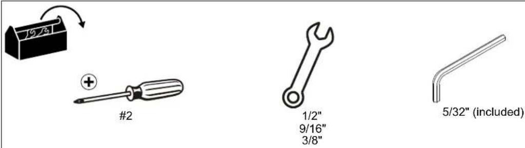
TOOLS REQUIRED FOR INSTALLATION
PARTS

(4 bags total - quantities listed per bag)
[Interface Bracket Hardware Kit]

A (4)
M6x16mm

B (4)
M6x25mm

C (4)
M8x20mm

D (4)
M8x30mm
natural_image
Technical line drawing of a mechanical component with mounting flanges and a central circular feature (no text or symbols)H (2)
[Mount assembly]
[Box-column Hardware Kit] - (2) - (Qty per bag)

U (2)
3/8-16×4"

V (2)
3/8-16

W (4)
3/8"

L (8)
[Interface bracket]

text_image
J (2) [2 x 4 cm][2 x 1 rail]
K (4)
[Side cover]


X(2)
1/4-20 x 1 1/4"
Y (8)
1/4 × 3/4"
Z (1)
5/32"
INSTALLATION
IMPORTANT ! : The following procedure assumes that:
- Two UL Listed ODAC Series Floor/Ceiling Columns (not included) have been properly installed following instructions provided with plates and pipes.
Attaching Mount to ODAC Series Column

CAUTION: WATCH FOR PINCH POINTS! Do not place fingers between movable parts.
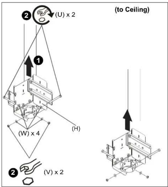
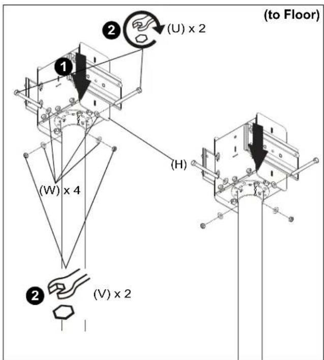
- Slide mount assemblies (H) onto ODAC Series Floor/Ceiling Columns. (See Figure 1) or (See Figure 2)
- Use two 3/8-16 x 4" hex head tapping bolts (U), four 3/8" washers (W) and two 3/8-16 hex nuts (V) to secure each mount assembly (H) to each column. (See Figure 1) or (See Figure 2)
text_image
(to Ceiling) (U) x 2 (H) (W) x 4 (V) x 2Figure 1
text_image
(to Floor) (U) x 2 (H) (W) x 4 (V) x 2Figure 2
3. Install 1/4-20 x 1 1/4" button head cap screws (X) into each mount assembly (H) to prevent column from rattling. (See Figure 3)

text_image
(X) x 2 (H) x 2Figure 3
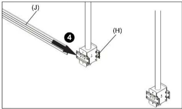
- Slide 2 x 1 rail (J) onto one of two assemblies (H) attached to column. (See Figure 4)
text_image
(J) ④ (H)Figure 4
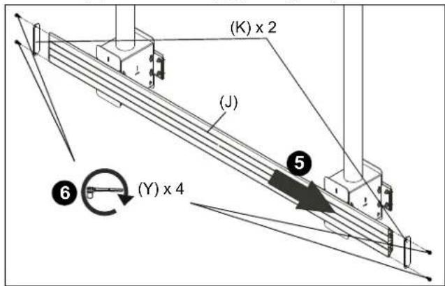
- Slide 2 x 1 rail (J) onto second assembly (K) attached to column. (See Figure 5)
- Use four 1/4 x 3/4" hex flange bolts (Y) to secure two side covers (K) to ends of rail (J). (See Figure 5)
text_image
(K) x 2 (J) ⑤ (Y) x 4 ⑥Figure 5
- Tighten four bolts on back of each assembly to secure rail (J) in place.
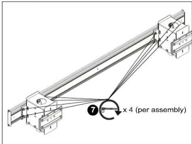
text_image
7 x 4 (per assembly)Figure 6
- Repeat Steps 4-7 to install second rail (J) to assemblies (H).
Attaching Interface Brackets to Display
- Lower the latch mechanism on each interface bracket (L). (See Figure 7)
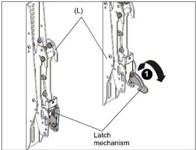
text_image
(L) Latch mechanismFigure 7
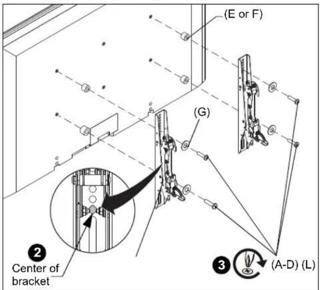
- Align the center of the interface bracket (L) with center of screen. (See Figure 8)
NOTE: The diamond-shape hole in the bracket corresponds to the center of the mount.
text_image
(E or F) (G) Center of bracket (A-D) (L)Figure 8

WARNING: IMPROPER INSTALLATION CAN LEAD TO DISPLAY FALLING CAUSING SERIOUS PERSONAL INJURY OR DAMAGE TO EQUIPMENT! Using screws of improper size may damage your display. Properly sized screws will easily and completely thread into display mounting holes. If spacers are required, be sure to use longer screws of the same diameter.
- Select correct screws, spacers (if necessary) and washers from the hardware bag (A-G) and attach brackets (L) to back of screen. (See Figure 8)
Attaching Displays to Ceiling Mounts

WARNING: Exceeding the weight capacity can result in serious personal injury or damage to equipment! It is the installer's responsibility to make sure the combined weight of all components located within the mounting system of the OLCB2X1U mounts does not exceed 500 lbs (226.8 kg) total or 125 lbs (56.7 kg) per display.
| 125 125 | |
| 125125 |
-
Ensure that the latch mechanisms on interface brackets (L) are already lowered. (See Figure 9)
-
While supporting both sides of display, lower display onto ceiling mount, hooking top of interface brackets onto front of ceiling mount. (See Figure 9)

WARNING: IMPROPER INSTALLATION CAN LEAD TO DISPLAY FALLING CAUSING SERIOUS PERSONAL INJURY OR DAMAGE TO EQUIPMENT! The display MUST be centered on the ceiling mount.
- Raise the latch mechanism on both interface brackets to lock bracket in place. (See Figure 9)

text_image
(OLCM1U shown) ② ③ Latch mechanismFigure 9
-
Fasten bracket against ceiling mount extrusion using one 10-24 x 1/2" socket head cap screw (M) per bracket. (See Figure 10)
-
Repeat Steps 1-4 for other interface brackets.
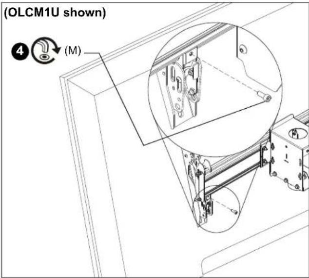
text_image
(OLCM1U shown) ④ (M)Figure 10
Adjustments

CAUTION: Watch for pinch points! Do not place fingers between movable parts.
Tilt

CAUTION: Watch for pinch points! Do not place fingers between movable parts.
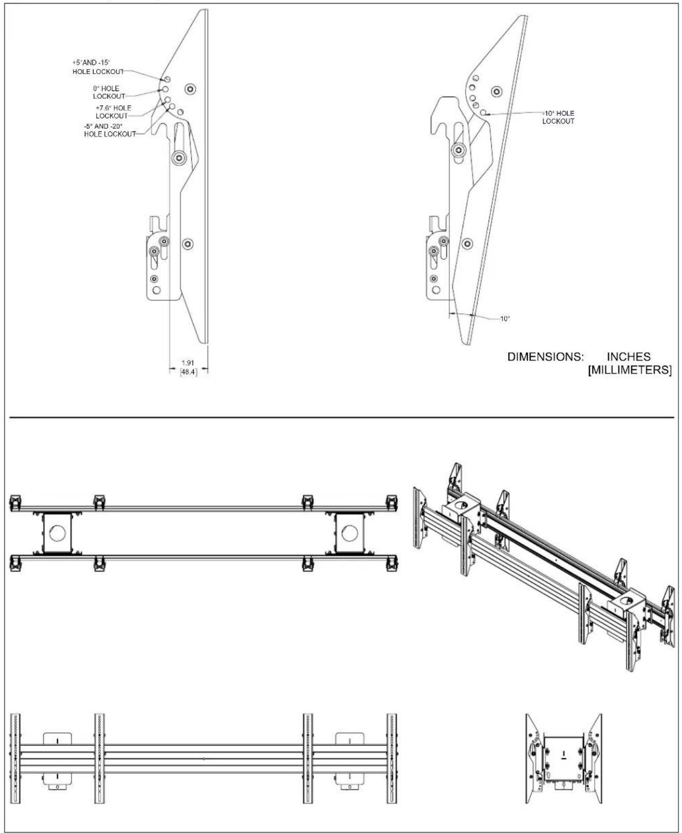
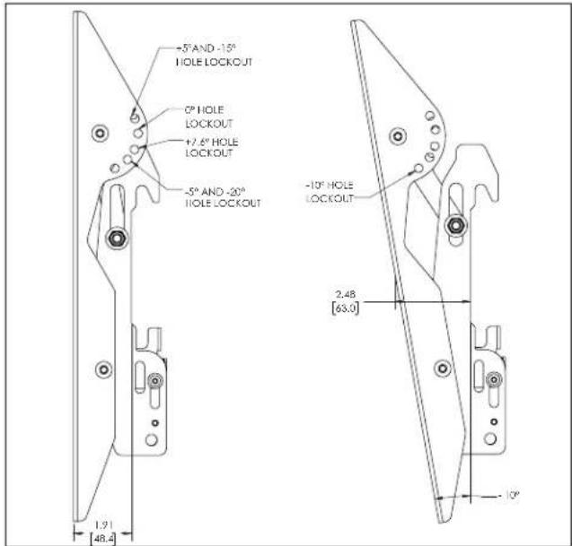
The interface brackets allow -7.6^ to 20^ tilt, and can be locked at -7.6^ , -5^ , 0^ , 5^ , 10^ , 15^ and 20^ tilt. (See Figure 11)
text_image
-5° AND -15° HOLE LOCKOUT 0° HOLE LOCKOUT +2.6° HOLE LOCKOUT -5° AND -20° HOLE LOCKOUT -10° HOLE LOCKOUT 2.48 [63.0] 1.91 [48.4] 10°Figure 11
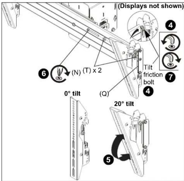
- If necessary, loosen button head tilt friction bolt (located on side of interface bracket). (See Figure 12)
- Adjust tilt as required. (See Figure 12)
- The tilt may be locked at -7.6°, -5°, 0°, 5°, 10°, 15° and 20° using one 1/4-20 x 2" Phillips head screw (N), one 1/4-20 lock nut (Q) and two 1/4" washers (T) per interface bracket. (See Figure 11) and (See Figure 12)
NOTE: Use of washers (T) is optional.
9. Tighten button head tilt friction bolt as necessary.
text_image
(Displays not shown) (6) (N) (T) x 2 (T) × 2 0° tilt (Q) Tilt friction bolt 4 7 5 20° tiltFigure 12
Level Adjustment
- Adjust level adjustment screws to change roll position. The roll may be adjusted 1" in either direction. (See Figure 13)

text_image
or level adjustment screwsFigure 13
Latch Lock/Security
IMPORTANT ! : In order to prevent interface latch from getting loose due to strong winds, the latch MUST be locked either using a padlock or locking bolt (N) and 5/16-18 hex nuts (Q). This is NOT optional!
Using Padlocks (Security)
- Add padlock (not included) to each interface bracket to lock latch and to provide security for displays. (See Figure 14)

text_image
Padlock (Optional) (OLCM1U shown)Figure 14
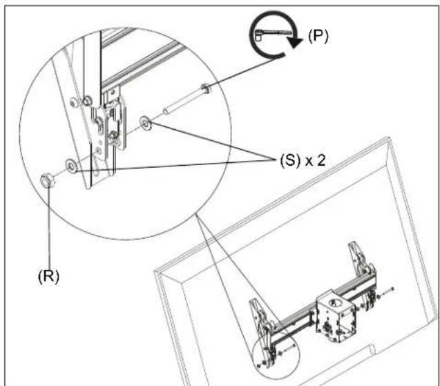
Using Bolts/Nuts
NOTE: This will keep latch from opening but does not provide additional security for the displays.
- Use 5/16-18 x 2" hex head carriage bolt (P), 5/16-18 hex nut (R) and two 5/16" washers (S) to lock each interface bracket latch in place. (See Figure 15)
text_image
(P) (S) x 2 (R)Figure 15

CHIEF®
Our Mounts. Your Vision.
Chief, a products division of Milestone AV Technologies
8800-003023 Rev01
©2018 Milestone AV Technologies
www.milstone.com
12/18
USA/International A 6436 City West Parkway, Eden Prairie, MN 55344
P 800.582.6480 / 952.225.6000
F 877.894.6918 / 952.894.6918
Europe A Franklinstraat 14, 6003 DK Weert, Netherlands
P +31 (0) 495 580 852
F +31 (0) 495 580 845
Asia Pacific A Office No. 918 on 9/F, Shatin Galleria
18-24 Shan Mei Street
Fotan, Shatin, Hong Kong
P 852 2145 4099
F 852 2145 4477
