
TTL-100 - Camera DataVideo - Free user manual and instructions
Find the device manual for free TTL-100 DataVideo in PDF.


| Product Type | Teleprompter Kit (ENG and Freestanding) |
| Brand | DataVideo |
| Model | TP-700 (referred as TTL-100 in request) |
| Display | 15-inch LCD with integrated dvPrompter Plus software |
| LCD Native Resolution | 1024 x 768 |
| LCD Brightness | 350 NIT |
| Dimensions (Prompter Max) | Width 430 mm, Height 345 mm, Depth 820 mm |
| Net Weight | 6.3 kg |
| Gross Weight | 7.8 kg |
| Power Supply | 12V 2A DC (mains adapter supplied) or V-Lock battery |
| Operating Temperature | 0 – 40°C |
| Remote Control | Via Ethernet (WebUI), optional WR-500 wired handheld, FS-30 foot switch, generic presentation clickers, Contour Shuttle Xpress |
| Connectivity | HDMI input and output, Ethernet, USB, 3.5mm jack for WR-500 |
| Software | dvPrompter Plus built-in (text scripts, slides, playlists, real-time editing) |
| Glass Type | 70/30 mirror glass (hand wash only, avoid abrasives) |
| Warranty | 1 year standard, extendable to 3 years with registration |
| Package Contents | Prompter rail, LCD unit, glass frame with glass, hood, cables, mouse, power supply, tools, and more (see manual) |
| Supported Languages | English, Dutch, Spanish, Portuguese, Russian |
Frequently Asked Questions - TTL-100 DataVideo
User questions about TTL-100 DataVideo
0 question about this device. Answer the ones you know or ask your own.
Ask a new question about this device
Download the instructions for your Camera in PDF format for free! Find your manual TTL-100 - DataVideo and take your electronic device back in hand. On this page are published all the documents necessary for the use of your device. TTL-100 by DataVideo.
USER MANUAL TTL-100 DataVideo
ENG & Freestanding
TELEPROMPTER KIT
TP-700
Instruction Manual
Contents
FCC COMPLIANCE STATEMENT ....4
WARNINGS AND PRECAUTIONS ....4
GLASS-HANDLE WITH CARE....4
WARRANTY....5
STANDARD WARRANTY....5
REGISTER FOR 3 YEAR WARRANTY ....5
DISPOSAL 5
PACKING LIST 6
PRODUCT OVERVIEW......8
FEATURES....8
ASSEMBLY - TP-700 9
ASSEMBLY-ENG CONFIGURATION 9
ASSEMBLY-FREESTANDING CONFIGURATION 11
ASSEMBLY – OPTIONAL TALENT MONITOR 14
CONNECT A PC/LAPTOP FOR CONTROL AND MONITORING OVER IP 15
DIRECT ETHERNET CONNECTION 15
CONNECTION VIA A ROUTER / DHCP LAN 15
CAMERA EXPOSURE AND THE 70/30 MIRROR GLASS....16
CLEANING THE 70/30 GLASS....16
OPTIONAL TELEPROMPTER REMOTE CONTROLS....17
WR-500 HANDHELD CONTROLLER 17
Control Buttons 17
Remote Accessories....18
Lanyard Necklace 18
CR2032 Battery 18
FS-30 FOOT SWITCH....19
Control Buttons 19
GENERIC PRESENTATION CLICKERS 19
Control Buttons 19
CONTOUR SHUTTLE XPRESS 20
Setup....20
Control Buttons 23
DVPROMPTER PLUS APP 24
DOCUMENTS SCREEN....24
CREATING AND EDITING TEXT SCRIPTS AND SLIDES 24
Text Scripts 24
Slides....25
Exporting Slides from PowerPoint 25
Exporting Slides from Keynote....26
Importing Slides 27
REAL TIME EDITING....28
PLAYLISTS 28
Adding a Script to the Playlist 28
Adding HDMI IN to the Playlist....29
Changing the Playlist Order....29
CONTROL 29
Via the Device (USB Mouse)....29
Via the Web Interface....29
Keyboard Shortcuts....30
Using Optional Hardware Remote Controls....30
MENU BAR....31
Settings....31
SYNCHRONIZING MULTIPLE DEVICES....33
Via HDMI 33
Via Ethernet....33
USING THE HDMI INPUT 34
HARDWARE MIRRORING 34
CONNECTING AN EXTERNAL DISPLAY....35
UPDATING THE APP & FIRMWARE....36
Updating the Monitor Firmware 36
Updating the App 36
SPECIFICATIONS 38
SERVICE AND SUPPORT ....40
Disclaimer of Product and Services
The information offered in this instruction manual is intended as a guide only. At all times, Datavideo Technologies will try to give correct, complete and suitable information. However, Datavideo Technologies cannot exclude that some information in this manual, from time to time, may not be correct or may be incomplete. This manual may contain typing errors, omissions or incorrect information. Datavideo Technologies always recommend that you double check the information in this document for accuracy before making any purchase decision or using the product. Datavideo Technologies is not responsible for any omissions or errors, or for any subsequent loss or damage caused by using the information contained within this manual. Further advice on the content of this manual or on the product can be obtained by contacting your local Datavideo Office or dealer.
FCC Compliance Statement
This device complies with part 15 of the FCC rules. Operation is subject to the following two conditions:
- This device may not cause harmful interference, and
- This device must accept any interference received, including interference that may cause undesired operation.
Warnings and Precautions

- Read all of these warnings and save them for later reference.
- Follow all warnings and instructions marked on this unit.
- Unplug this unit from the wall outlet before cleaning. Do not use liquid or aerosol cleaners. Use a damp cloth for cleaning.
-
Do not use this unit in or near water.
-
Do not place this unit on an unstable cart, stand, or table. The unit may fall, causing serious damage.
-
Slots and openings on the cabinet top, back, and bottom are provided for ventilation. To ensure safe and reliable operation of this unit, and to protect it from overheating, do not block or cover these openings. Do not place this unit on a bed, sofa, rug, or similar surface, as the ventilation openings on the bottom of the cabinet will be blocked. This unit should never be placed near or over a heat register or radiator. This unit should not be placed in a built-in installation unless proper ventilation is provided.
-
This product should only be operated from the type of power source indicated on the marking label of the AC adapter. If you are not sure of the type of power available, consult your Datavideo dealer or your local power company.
-
Do not allow anything to rest on the power cord. Do not locate this unit where the power cord will be walked on, rolled over, or otherwise stressed.
-
If an extension cord must be used with this unit, make sure that the total of the ampere ratings on the products plugged into the extension cord do not exceed the extension cord rating.
-
Make sure that the total amperes of all the units that are plugged into a single wall outlet do not exceed 15 amperes.
-
Never push objects of any kind into this unit through the cabinet ventilation slots, as they may touch dangerous voltage points or short out parts that could result in risk of fire or electric shock. Never spill liquid of any kind onto or into this unit.
-
Except as specifically explained elsewhere in this manual, do not attempt to service this product yourself. Opening or removing covers that are marked "Do Not Remove" may expose you to dangerous voltage points or other risks, and will void your warranty. Refer all service issues to qualified service personnel.
-
Unplug this product from the wall outlet and refer to qualified service personnel under the following conditions:
a. When the power cord is damaged or frayed;
b. When liquid has spilled into the unit;
c. When the product has been exposed to rain or water;
d. When the product does not operate normally under normal operating conditions. Adjust only those controls that are covered by the operating instructions in this manual; improper adjustment of other controls may result in damage to the unit and may often require extensive work by a qualified technician to restore the unit to normal operation;
e. When the product has been dropped or the cabinet has been damaged;
f. When the product exhibits a distinct change in performance, indicating a need for service.
GLASS – Handle with Care

This product contains a sheet of 70/30 mirror glass please handle it with care.
To avoid a risk of damage or injury please follow this instruction manual and use caution when transporting, un-packing, cleaning, assembling or dis-assembling this part of the product.
Warranty

Standard Warranty
- Datavideo equipment are guaranteed against any manufacturing defects for one year from the date of purchase.
- The original purchase invoice or other documentary evidence should be supplied at the time of any request for repair under warranty.
- The product warranty period begins on the purchase date. If the purchase date is unknown, the product warranty period begins on the thirtieth day after shipment from a Datavideo office.
- All non-Datavideo manufactured products (product without Datavideo logo) have only one year warranty from the date of purchase.
- Damage caused by accident, misuse, unauthorized repairs, sand, grit or water is not covered under warranty.
- Viruses and malware infections on the computer systems are not covered under warranty.
- Any errors that are caused by unauthorized third-party software installations, which are not required by
our computer systems, are not covered under warranty.
- All mail or transportation costs including insurance are at the expense of the owner.
- All other claims of any nature are not covered.
- All accessories including headphones, cables, and batteries are not covered under warranty.
- Warranty only valid in the country or region of purchase.
- Your statutory rights are not affected.
Register for 3 Year Warranty
- All Datavideo products purchased after July 1st, 2017 are qualified for a free two years extension to the standard warranty, providing the product is registered with Datavideo within 30 days of purchase.
- Certain parts with limited lifetime expectancy such as LCD panels, DVD drives, Hard Drive, Solid State Drive, SD Card, USB Thumb Drive, Lighting, Camera module, PCIe Card are covered for 1 year.
- The three-year warranty must be registered on Datavideo's official website or with your local Datavideo office or one of its authorized distributors within 30 days of purchase.
Disposal
For EU Customers only - WEEE Marking

This symbol on the product or on its packaging indicates that this product must not be disposed of with your other household waste. Instead, it is your responsibility to dispose of your waste equipment by handing it over to a designated collection point for the recycling of waste electrical and electronic equipment. The separate collection and recycling of your waste equipment at the time of disposal will help to conserve natural resources and ensure that it is recycled in a manner that protects human health and the environment. For more information about where you can drop off your waste equipment for recycling, please contact your local city office, your household waste disposal service or the shop where you purchased the product.

CE Marking is the symbol as shown on the left of this page. The letters "CE" are the abbreviation of French phrase "Conformité Européenne" which literally means "European Conformity". The term initially used was "EC Mark" and it was officially replaced by "CE Marking" in the Directive 93/68/EEC in 1993. "CE Marking" is now used in all EU official documents.
Packing List
| Item | Description | Quantity |
| A | Main TP-700 ENG prompter rail | 1 |
| B | Smaller rail with spacer block for mounting item F | 1 |
| C | 1/4" Screws Length 27mm secures item Aor AA to B | 2 |
| D1 | Hex Tool (Silver) for counter sunk Hex head screws | 1 |
| D2 | Hex Tool (Silver) for Glass Frame Hex screws | 1 |
| D3 | Hex Tool (Silver) for VESA Hex screws | 1 |
| E | 16mm 1/4 screws with washer to attach item F to item B (With red dot) | 2 |
| F | 15" LCD control unit | 1 |
| G | Glass frame with 4 Velcro straps | 1 |
| H | Wing nut screws 1/4" Length 19mm secures item A or AA to G | 2 |
| I | Cloth Snood/Hood with Velcro straps | 1 |
| J | 70/30 Glass sheet with Green and Red stickers | 1 |
| K | Snood/Hood support wire | 1 |
| L | 1/4" Camera securing screws length 16mm | 2 |
| M | 1/4" Camera securing screws length 31mm | 2 |
| N | Camera riser block 15mm thick | 1 |
| O | USB Mouse | 1 |
| P | Adapter screw to convert 3/8" hole to 1/4" hole | 1 |
| Q | 1/4" Counter sunk hex head screw length 16mm | 1 |
| R | 1/4" Counter sunk hex head screw length 31mm | 1 |
| S | Talent monitor vertical mounting rail | 1 |
| T | Talent monitor VESA adapter plate | 1 |
| U | 14mm M4 screws for mounting 75MM VESA monitors | 4 |
| V | Universal mains PSU | 1 |
| W | Ethernet Cable 5MNote: An optional 12V PoE adapter is available, contact your Datavideo sales representative for more information. | 1 |
| X | 3.5mm input adapter for WR-500 remote control | 1 |
| Y | 12V D-Tap Cable | 1 |
| Z | 12mm M4 Screws to secure item J | 2 |
| AA | Small rail to attached item G to B in a freestanding configuration | 1 |
| BB | 16MM M4 screw to attach item S to item B | 2 |
| CC | 8mm M4 screws for mounting item T | 4 |
| CCC | 12mm M4 screws for mounting item 100MM VESA monitors | 4 |

NOTE: Depending on your order, your TP-700 kit could have been supplied with one of a range of remote controls – for more information on the remote controls please speak with your local Datavideo supplier or check our website www.datavideo.info for details.

Product Overview
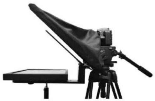
Studio teleprompter with extra-large trapezoid glass. TP-700 features a bright 15" LCD screen with dvPrompter Plus app built-in. There is no need to run software on a laptop.
The Datavideo Prompter Kit, TP-700, can be used with ENG style cameras, where the camera is mounted directly to the teleprompter rig, or with any camera in its freestanding configuration.
Prepared scripts or cue sheets can be easily copied and pasted into the dvPrompter Plus app software and scrolled at a set automatic rate or controlled by a user with the optional wired / wireless remote for a more natural result. A number of clear fonts, colours and text sizes are available making reading comfortable from a variety of distances.
Features
• ENG and Freestanding configurations
- dvPrompter Plus software built in
- Can be powered by the mains or a V-Lock battery
- HDMI input and HDMI output can be used to connect multiple TP-700s together
- The HDMI input also allows the built-in tablet to be used as a HDMI monitor with third party software if required
• Fully controllable via Ethernet
• An optional 12V PoE adapter is available
- Supports up to 19" talent monitor on the front, VESA 75 and 100 mounts
- Optional handheld and foot controllers are available
- Can also be controlled using standard wireless presentation remotes and the Contour Shuttle Xpress
Assembly - TP-700
Assembly – ENG Configuration

- Attach/screw the tripod's own quick release plate to the screw holes on the base of the TP-700 ENG Prompter rail, item A.
The long slot will be to the rear of the camera position and the four holes in the rail will be towards the lens of the camera.
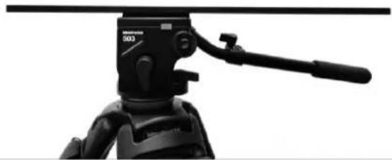
- Now slide and secure the tripod plate, with prompter rail, item A, onto the head of the tripod or dolly.

- Use the hand screws item C, to secure the lower part of the ENG Prompter Frame item B in place using the counter sunk holes in the main part of the frame item A.
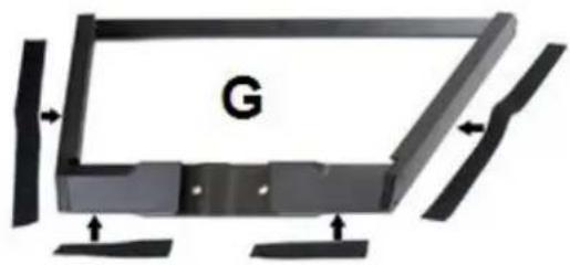
Note: There should be two holes left free in front of this mounting position for the Glass frame.
- There are four adhesive Velcro straps packed inside the Snood/Hood, item I. Peel off the white paper backing before applying these straps to the Glass Frame, item G.
Apply the two long Velcro strips to the Glass Frame edges on the Left side and Right side. Then apply the two smaller Velcro strips to the Bottom Left and Right sides of the Glass Frame edge.

Be careful not to cover any screws and keep them straight.
- Slide the Glass frame, item G, on to the front of the TP-700 ENG prompter rail, item A. Ensure the upper part of the Glass Frame, Item G, is leaning away from the camera position and secure with the two wing nut screws, item H.
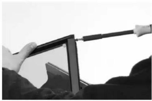
- There are two slots on the inside left and right of the Glass Frame, Item G. Guide/slide 70/30 Mirror Glass sheet, item J, into these slots from above.
The Red circle sticker on the Mirror Glass, item J, should be facing camera position / lens.
The Green circle sticker on item J should be facing toward the on screen talent / commentator.
-
Optionally, secure the glass sheet within the frame using the small M4 screws, Item Z, at the top of each frame slot. The hex tool, item D2 can be used to tighten the screws.
-
Fit the 15" LCD control unit, Item F, to the lower part of the ENG Prompter Frame item B using the 1/4 thumb screws, Item E. Ensure the LCD control unit has the red power button facing the front of the TP-700.

- Decide if you need to use the TP-700 MKII ENG camera riser block or not.
Ideally you want the lens of your camera positioned as close to the centre of the 70/30 mirror glass as possible.
In some cases depending on your camera and its ENG camera plate the camera lens may already be high enough.

Tripod adapter plate shown without riser block
- Secure the ENG tripod adapter plate (not supplied) and riser block item N (if required) to the prompter rail item A using two of the riser screws provided, items L or M. These screws go through the long slot on the riser block and prompter rail and into the base of the tripod adapter plate.
Two screw sets are provided, the long set (Item M 31mm long) is for when using the riser block. The short set (Item L 16mm long) when just using the camera plate on its own.
Items Q and R are provided in case the tripod adapter plate and riser block need to be positioned over the tripod head.

- You can now mount the ENG camera to the tripod adapter plate. Take care to protect the camera lens and the 70/30 mirror glass. If necessary slide everything further along the prompter frame.
The tip of the lens should be about 1 to 2 cm away from the centre of the 70/30 Mirror Glass.
It may be a good idea to remove the lens sun hood if this is possible.


-
Fit the Snood / Hood support wire, item K.. This stops the cloth Snood / Hood from dipping in front of the camera lens. There are two sets of holes in the glass frame for this Snood / Hood support wire.
-
Fit the cloth Snood / Hood, item I, around the lens and to the Glass Frame edges, item G. The Velcro strips marry the Snood/Hood to the Glass Frame.
-
Pull the draw cord to secure the cloth Snood / Hood, item I, around the camera lens and to shut out light from the camera side.
-
Turn on the 15" LCD control unit by connecting the mains power supply, Item V or connecting V-Lock battery using the D-Tap cable, Item Y. The dvPrompter Plus software will automatically load, please see the appropriate section of this manual for detailed software usage instructions.
- If required adjust the position of the 15" LCD control unit.
- Adjust the camera exposure settings as necessary. See the Camera Exposure section of this manual.
Assembly – Freestanding Configuration
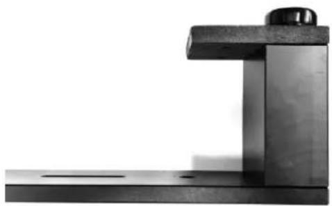

- Use the hand screws item C, to secure the lower part of the ENG Prompter Frame item B in place using the counter sunk holes in the freestanding rail item AA.
Note: There should be two holes left free in front of this mounting position for the Glass frame.
- There are four adhesive Velcro straps packed inside the Snood/Hood, item I. Peel off the white paper backing before applying these straps to the Glass Frame, item G.
Apply the two long Velcro strips to the Glass Frame edges on the Left side and Right side. Then apply the two smaller Velcro strips to the Bottom Left and Right sides of the Glass Frame edge.
Be careful not to cover any screws and keep them straight.


-
Slide the Glass frame, item G, on to the front of the freestand rail, item AA. Ensure the upper part of the Glass Frame, Item G, is leaning away from the camera position and secure with the two wing nut screws, item H.
-
There are two slots on the inside left and right of the Glass Frame, Item G. Guide/slide 70/30 Mirror Glass sheet, item J, into these slots from above.
The Red circle sticker on the Mirror Glass, item J, should be facing camera position / lens.
The Green circle sticker on item J should be facing toward the on screen talent / commentator.
-
Optionally, secure the glass sheet within the frame using the small M4 screws, Item Z, at the top of each frame slot. The hex tool, item D2 can be used to tighten the screws.
-
Fit the 15" LCD control unit, Item F, to the lower part of the ENG Prompter Frame item B using the ¼ thumb screws, Item E. Ensure the LCD control unit has the red power button facing the front of the TP-700.
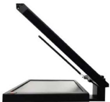

- You can now fit the lower part of the ENG Prompter Frame item B to your tripod or light stand using one of the three 3/8 threaded holes, use the 3/8 to ¼ adapter, Item P if required. Typically, the central 3/8 hole provides the correct balance if not using a talent monitor, the front 3/8 hole should be used with a talent monitor.
Note: A light stand should only be used when using the TP-700 without a talent monitor, always use an appropriately rated tripod when using a talent monitor.
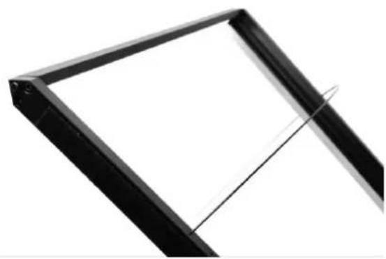
- Fit the Snood / Hood support wire, item K.. This stops the cloth Snood / Hood from dipping in front of the camera lens. There are two sets of holes in the glass frame for this Snood / Hood support wire.

- Fit the cloth Snood / Hood, item I, to the Glass Frame edges, item G. The Velcro strips marry the Snood/Hood to the Glass Frame.
-
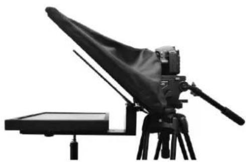
Position the TP-700 in front of the camera lens and pull the draw cord to secure the cloth Snood / Hood, item I, around the camera lens and to shut out light from the camera side.
-
Turn on the 15" LCD control unit by connecting the mains power supply, Item V or connecting V-Lock battery using the D-Tap cable, Item Y. The dvPrompter Plus software will automatically load, please see the appropriate section of this manual for detailed software usage instructions.
- If required adjust the position of the 15" LCD control unit.
- Adjust the camera exposure settings as necessary. See the Camera Exposure section of this manual.
Assembly – Optional Talent Monitor

-
Attach the talent monitor vertical mounting rail, item S, to secure the lower part of the ENG Prompter Frame item B using the M4 screws, item BB.
-
If your monitor has a 75MM VESA mount, attach the monitor directly to the vertical mounting rail, item S using the 14mm M4 screws, item U.
-
If your monitor has a 100MM VESA mount, first attach the VESA adapter plate, item T to the vertical mounting rail, item S using the 8mm M4 screws, Item CC, then attach the monitor to the VESA adapter plate using the 12MM M4 screws, item CCC.
Connect a PC/Laptop for Control and Monitoring over IP
The TP-700 has the Datavideo dvPrompter Plus app built in. The TP-700 can be monitored and controlled from any Ethernet connected device with a modern web browser.
Direct Ethernet Connection
- Connect an Ethernet cable between the TP-700 and your PC/Laptop
- Power on the TP-700, the dvPrompter Plus app will open automatically
- The TP-700 has the static IP address 192.168.10.10 by default, we must also set a static IP address on the PC/Laptop
- Turn on the Windows computer and set it to static IP set up within the Windows Network and Sharing Centre. In our example the computer is given the following IP settings so that the computer matches the same IP range as the TP-700.
- Open a web browser and navigate to http://192.168.10.10:9789, you will see the main control page.
- Please see the appropriate section of this manual for software operation instructions

Connection via a Router / DHCP LAN
- Connect the supplied USB mouse to the TP-700 and power it on
- Once the TP-700 has booted, right click to close the dvPrompter Plus app
- Navigate to Settings > More > Ethernet
- Change the 'Ethernet IP mode' from static to DHCP
- Connect the TP-700 to your existing LAN
- Open the dvPrompter Plus app
- Click the menu bar and then 'Network'
- The network control URL will be shown as below
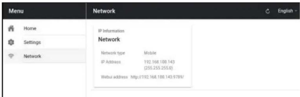
- Please see the appropriate section of this manual for software operation instructions.
Camera Exposure and the 70/30 Mirror Glass
After setting up the camera with the 70/30 glass in front of the lens adjust the camera set up and white balance. This is because the 70/30 Glass affects the camera exposure by approximately 1 stop almost like the effect of a neutral density filter. Consult your camera manual for further help and advice with its exposure and white balance settings.
Cleaning the 70/30 Glass

This product contains a sheet of 70/30 glass please handle it with care.
To avoid a risk of damage or injury please follow this instruction manual and use caution when transporting, un-packing, cleaning, assembling or dis-assembling this part of the product.
Datavideo recommend cleaning the glass regularly to remove dust and finger print marks. This will ensure the best image quality is recorded when the camera is looking through the glass.
Never attempt to clean the glass whilst it is mounted in the prompter instead remove it carefully from the prompter, clean the glass and then re-install it into the prompter frame. Handle the glass carefully using the cloth covered edges of the glass at all times.
To retain the required qualities of the glass and to avoid scratching the glass during cleaning.
- Never use abrasive cloths, pads or abrasive based cleaning fluids on the glass.
- Never use cleaning fluids based on an acid or vinegar solution.
Place the glass on a soft, stable, dirt and lint free work surface such as a table with a clean cloth already laid out on it. Then use a second clean, lint free, soft cloth to clean the glass.
Do not apply cleaning fluids to the glass directly, instead apply or spray a small amount of the cleaning fluid onto the cloth. Proceed to clean the glass and work in a light circular motion with the cloth. Ensure all finger marks and streaks are gone before turning the glass over and repeating with the other side.

Optional Teleprompter Remote Controls
The TP-700 prompter can be controlled and monitored in real time over IP using a laptop or tablet.
Optionally you use the Datavideo WR-500 handheld controller, the Datavideo FS-30 foot switch controller, generic 2.4 Ghz wireless presentation clickers or the Contour Shuttle Xpress.
Please see below for more details:
WR-500 Handheld Controller

Optionally you purchase the WR-500 remote control for direct wired control. The WR-500 remote control supports Bluetooth and Wired operation, only wired operation is supported by TP-700.
The WR-500 supports control of both scrolling text and slides.
When first removed from the retail package the WR-500 remote is already in wired mode. When a button is pressed a RED LED will flash.
In wired mode, the remote needs to be physically cabled to the TP-700. A four-pole jack to jack plug cable is provided with this remote.
One end of the cable fits into the 3.5mm input adapter (Item I, supplied with the TP-700). The other end plugs into the jack socket on the WR-500 remote.
NOTE: When using this remote in wired mode the dvPrompter Plus app should also be set to Wired – WR-500 in the Remote menu option.
Control Buttons
| Button | Whilst Scrolling Text | Whilst Paused | Slides |
| + | Speed up scroll | next break marker | Next slide |
| - | Slow down scroll | Previous break marker | Previous slide |
| »|| | Pause | Play | NA |
| «| | Reduce font size | Load previous script in playlist | Load previous script in playlist |
| |» | Increase font size | Load next script in playlist | Load next script in playlist |
| LED Indicators | |
| RED LED | Wired Mode |
| GREEN LED | Bluetooth 4 |
Remote Accessories
Lanyard Necklace
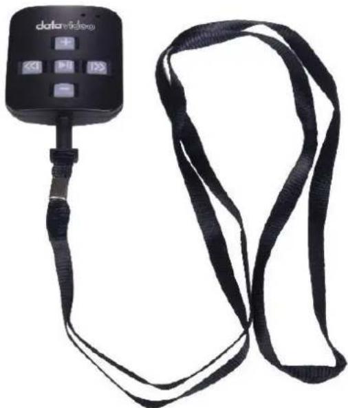
Plug the lanyard necklace into the jack plug socket.
CR2032 Battery
A CR2032 button battery is installed inside this remote. The original battery supplied (when new) is expected to last for 3 years under average / normal use.
If the remote is unreliable in Bluetooth mode, this can be an early sign the battery is low.

This button battery can be replaced by the user when it dies. Please remove the back case cover carefully to avoid user damage to the PCB or case. Then slide the old battery out.
Please ensure the new button battery is installed with the positive (+) side of the cell facing the (+) sign on the PCB battery slot.
FS-30 Foot Switch

Optionally you purchase the FS-30 foot switch control for direct wired control. The FS-30 foot switch connects via USB and offers three pedals with independent functions. The FS-30 uses non-contact photoelectric sensors for near silent operation.
The FS-30 supports control of both scrolling text and slides.
Control Buttons
The FS-30 will work all TP-700 teleprompters running dvPrompter Plus version 1581 or newer, please see the appropriate section of this manual for information on updating the dvPrompter Plus software.
Please connect the FS-30 to the white USB port on the teleprompters 15" LCD monitor, the FS-30 will work as soon as its connected, there is no need to set any control options within the dvPrompter Plus application.
The table below details the functions of each pedal.
| Button | Whilst Scrolling Text | Whilst Paused | Slides |
| Left Pedal | Slow down scroll | Previous break marker | Previous slide |
| Right Pedal | Speed up scroll | Next break marker | Next slide |
| Middle Peal | Pause | Play | NA |
Generic Presentation Clickers
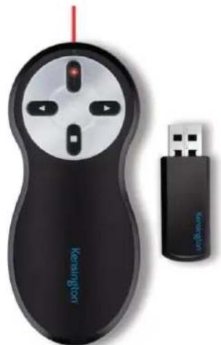
Most generic presentation clickers with a USB receiver are supported by TP-700s running dvPrompter Plus version 1581 or newer, please see the appropriate section of this manual for information on updating the dvPrompter Plus software.
We have provided support for control of both scrolling text and slides.
*The above is an example of a 2.4Ghz wireless presentation clicker with a USB receiver.
Control Buttons
Please connect the USB receiver to the white USB port on the teleprompters 15" LCD monitor, the presentation clicker will work as soon as its connected, there is no need to set any control options within the dvPrompter Plus application.
The table below details the functions the buttons commonly found on most presentation clickers.
| Button | Whilst Scrolling Text | Whilst Paused | Slides |
| Left < | Slow down scroll | Previous break marker | Previous slide |
| Right > | Speed up scroll | Next break marker | Next slide |
| Black Screen | Pause | Play | NA |
| Start | Pause | Play | NA |
Please Note: Whilst we have made every effort to support most generic presentation clickers, we cannot guarantee compatibility provide support for third party controllers.
Contour Shuttle Xpress
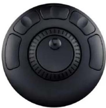
The Contour Shuttle Xpress is supported by TP-700s running dvPrompter Plus version 1726 or newer, please see the appropriate section of this manual for information on updating the dvPrompter Plus software.
We have provided support for control of both scrolling text and slides.
Setup
The Contour Shuttle Xpress should be connected to the operator's PC or Mac via USB, as long as the WebUI of the TP-700 is open on the operator's PC/Mac the Shuttle Xpress will have full control of the prompter over the local network.
- Open the WebUI of the TP-700, please see the appropriate section of this manual for more information on how to access the WebUI.
- Click the 'Settings' menu and enable the 'Hotkeys' option. The hotkeys should be set as below by default.
Enable Hotkeys


shift+left

shift+space

shift+0

shift+right

shift+x

shift+up

shift+down
- Download and install the Contour Shuttle Xpress software for your operating system https://contour-design.co.uk/products/multimedia-controller-xpress#details
- Download the Contour Shuttle Xpress settings file for dvPrompter Plus https://www.datavideo.com/global/file/download?id=4330
- Open the 'Contour Shuttle Configuration' application.
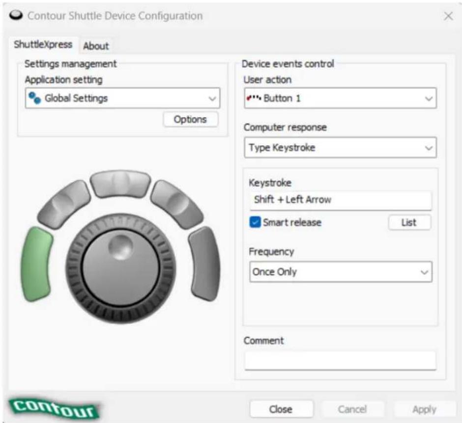
- We need to clear existing settings on the web browser that you will be using. In the example below, we assume the Google Chrome browser will be used.
- Select Google Chrome in the 'Application Setting' list as shown below.

- Click the 'Options' button and then 'Remove settings', click 'Yes' when prompted.
- Now click the 'Options' button and then 'Import Settings'
-
Select the Contour Shuttle Xpress settings file for dvPrompter Plus you previously downloaded and click 'Open'.
-
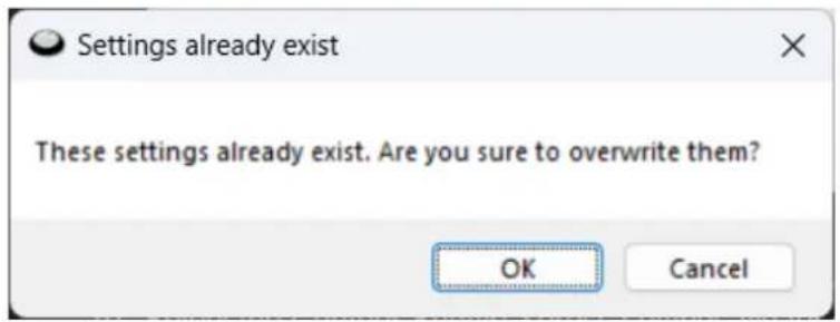
Click 'OK' again when prompted to overwrite the existing settings
- You will then be prompted to select a target application. Here we need to find the Google Chrome application and on Windows it's usually located under C:\Program Files\Google\Chrome\Application as shown below.
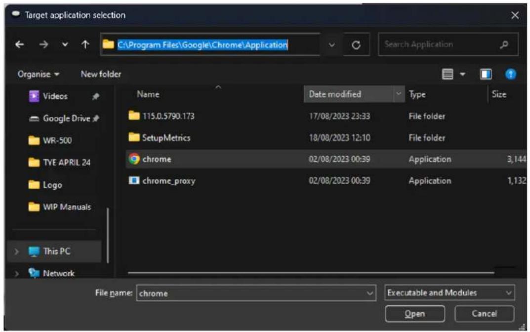
- Click 'Open' then 'Apply'
- Open the WebUI of the TP-700, the Shuttle Xpress will be operational as long as the WebUI is open.
- To control how aggressively the jog wheel adjusts the scroll speed you can adjust the 'Speed Adjustment Steps' option under the 'Settings' menu.

Control Buttons
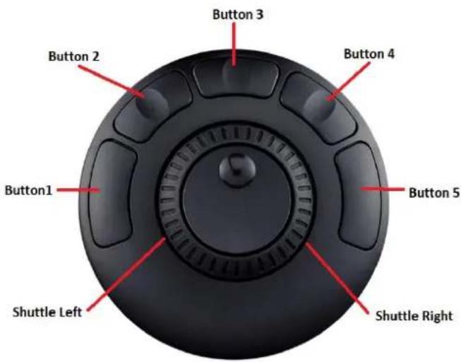
| Button | Whilst Scrolling Text | Whilst Paused | Slides |
| Button 1 | Reduce font size | Load previous item in playlist | Load previous item in playlist |
| Button 2 | Slow down scroll | Previous break marker | Previous slide |
| Button 3 | Pause | Play | NA |
| Button 4 | Speed up scroll | Next break marker | Next slide |
| Button 5 | Increase font size | Load next item in playlist | Load next item in playlist |
| Shuttle Left | Slow down scroll | NA | NA |
| Shuttle Right | Speed Up scroll | NA | NA |
dvPrompter Plus App
The TP-700 includes a fully unlocked version of the prompter Plus application, the application can be remotely managed via its WebUI, please see the appropriate section of this manual for information on how to access the WebUI.
Documents Screen
When you first access the WebUI, you will see the screen below.
The menu bar in the top left-hand corner provides access to the various settings menus.

Creating and Editing Text Scripts and Slides
Please see the appropriate section of this manual to understand how to access the app's remote control webui.
Text Scripts
To create a new script via the web interface simply tap the '+' button, enter a title and then enter the script body into the rich text editor. The script will be saved automatically when you close the rich text editor by tapping the 'X'.
To edit a script on the device simply tap the 'Edit' button, the script will be saved automatically when you close the rich text editor by tapping the 'X'.

Slides
In addition to text-based scripts you can now import your Powerpoint or Keynote presentation slides via the web interface, slides can be controlled using the hardware WR-500 control or the web based remote control interface. dvPrompter Plus supports seamlessly switching between text-based scripts and slides, you can even add slides and text-based scripts to a playlist
dvPrompter Plus supports mirroring slides in real time so your content is the right way around even when viewed via the mirror glass.
Please Note: Slide mode allows you to import slides as images, you must first export your slides as images from PowerPoint and Keynote
Exporting Slides from PowerPoint
- Before you convert slides to images, save your PowerPoint presentation to the PPTX or PPT format so you don't lose your work.
- Select the slide you want to save as an image. If you want to convert all the slides to images, select any slide.
- Select 'File' > 'Save As'. In PowerPoint for Mac, select 'File' > 'Export.'
- Choose the location where you want to save the file and enter a name for the image file.
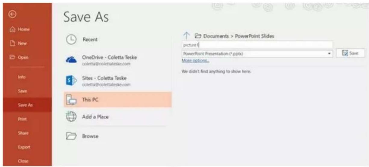
- Select the 'Save As' type down arrow to display a list of file formats. By default, PowerPoint Presentation (*.pptx) appears in the text box. On Mac, use the menu next to 'File Format'.
- Select the image format you wish to save your presentation. Choose JPEG.
- Select 'Save'. In PowerPoint for Mac, choose either 'Save Every Slide' or 'Save Current Slide Only', then select 'Export'.
- Choose whether you want to export 'All Slides' or 'Just This One'.
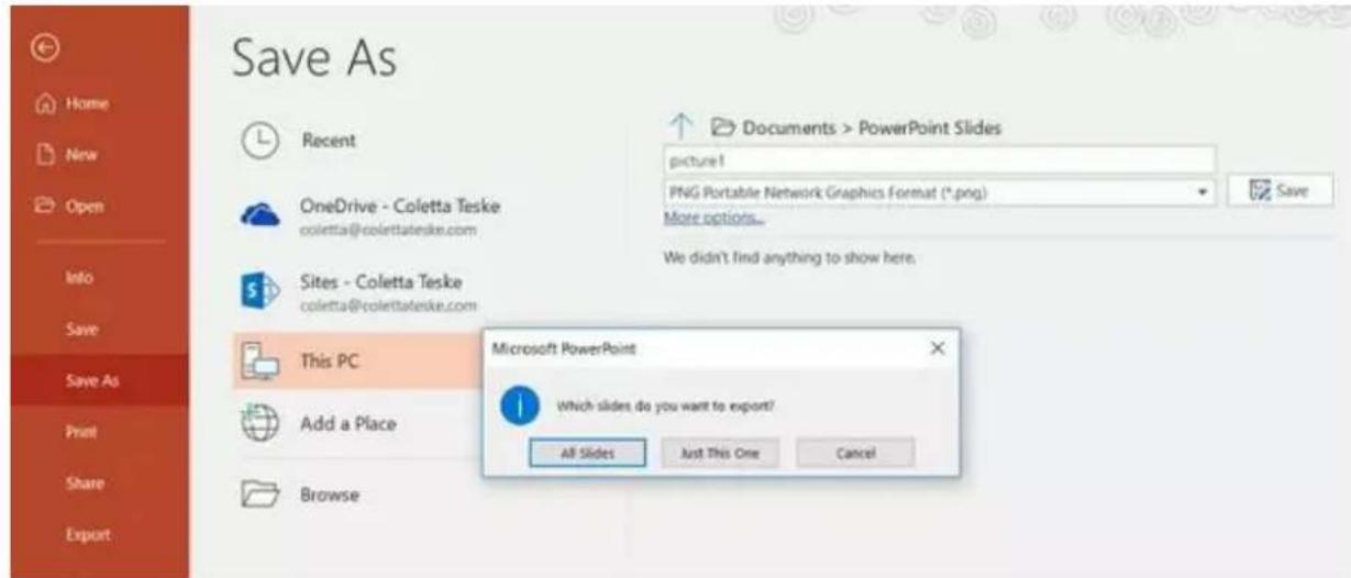
- The slide is saved in the selected file format.
If you convert more than one PowerPoint slide to separate image files, a new folder is created in the destination folder. This new folder uses the same name as the presentation. If you haven't saved the PowerPoint file, your exported slide images are saved in a folder with a default name, for example Presentation1.
Exporting Slides from Keynote
- Before you convert slides to images, save your presentation so you don't lose your work.
- In the top menu select 'File' > 'Export to' > 'Images'
- Select the 'JPEG (High Quality)' format and specify the range of slides that you want to save as images. If you want to save all the slides, check the point 'ALL'.
![DEMO_Annual_plan_16-9 [animation].key — Edited Table Chart Text Shape Media Comment Export Your Presentation PDF PowerPoint QuickTime HTML Images Keynote '09 Slides: All From: 1 to 74 Create an image for each stage of builds Format: JPEG (High Quality) Cancel Next...](/content/2026/06/1218454/images/1fb96126bd66fd04587bb572fc412868abe248bd8445f952f00b05d077f96508.jpg)
- Click 'Next'
- In the opened window select the folder where you want to save the images. Set the default name for the slide. During the export, KeyNote will automatically add the sequence number to this name.
Importing Slides
- Tap or click the '+' button and select the 'Slides' option.
- Enter a title, here I have used 'My Slides'

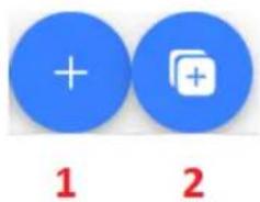
- To import multiple slides, click button 2. Button 1 can be used to add a single slide to an existing slide deck.
- Select all the slides you want to import, CTRL + A can be used to select all.


- Your slides will be imported in alphanumeric order, individual slides can be delete by clicking the blue trashcan icon next to each slide.

- You can choose to fit the images to the 'Height' or 'Width' of your device, select the option that avoids stretching of the slides based on the aspect ratio of the slides and your devices screen.
- The slides will be saved automatically when you close editor by tapping or clicking the 'X', you can also save changes using the blue save button on the top right corner of the editor.
To edit slides, simply tap or click the 'Edit' button, the slides will be saved automatically when you close the rich text editor by tap or clicking the 'X'
Real Time Editing
Real time editing allows you to modify a script that is currently on screen, simply modify the script via the web interface and watch it update in real time as soon as you save your changes.
Please Note: The scrolling text will pause momentarily while the changes are loaded.
Playlists
Adding a Script to the Playlist
Checking the 'In Playlist' option when creating or editing a script via the webui will allow the app to automatically load the next script in the list, it also allows you to quickly jump between scripts using the hardware remote control (see the control section of this guide for more information).

Adding HDMI IN to the Playlist
Checking the 'Keep HDMI IN on the playlist' option when creating or editing a script via the WebUI will allow you to use the HDMI input port as part of a playlist.
Changing the Playlist Order
To change the running order of the playlist simply click the horizontal bars to the right of the script name and drag to the desired position.
Test Script

Welcome

Control
Via the Device (USB Mouse)
Clicking the screen when a script is loaded will display the menu bar shown below.

A: Decrease text size when scrolling / jumping to previous script in playlist when paused
B: Start / Pause scrolling
C: Start / Pause scrolling
D: Increase text size when scrolling / jumping to next script in playlist when paused
E: Unload script and return to documents screen
Via the Web Interface
Please see the appropriate section of this manual to understand how to access the remote control webui of the app.
The network control interface is shown below.

A: Text Scripts: Decrease text size when scrolling / jumping to previous script in playlist when paused
B: Text Scripts: Start / Pause scrolling
C: Text Scripts: Start / Pause scrolling
D: Text Scripts: Increase text size when scrolling / jumping to next script in playlist when paused
E: Text Scripts: Unload script and return to documents screen
F: Text Scripts: Increase speed when scrolling / jumping to previous break marker when paused
Slides: Next slide
G: Text Scripts: Decrease speed when scrolling / jumping to next break marker when paused
Slides: Previous Slide
Keyboard Shortcuts
Keyboard shortcuts can be assigned to any of the buttons (A to G) detailed above. To enable and assign keyboard shortcuts first enable the 'Enable Hotkeys' option from the 'Settings' menu on the web interface, the default shortcuts are shown below.

To change a shortcut simply left click the button you want to assign with the mouse and then press the key combination you want to assign.
Please Note: Take care not to assign key combinations that are assigned to system functions or that will be used when editing.
Using Optional Hardware Remote Controls
Please see the Optional Teleprompter Remote Controls section of this manual for more information.
Menu Bar
Clicking the menu bar (found in the top left-hand corner of the documents screen will display the menu shown below, you will see the following options:
Home – Return to the documents screen
Settings – Display all app settings
Network – Display the address required to access the app from any device with a web browser over the local Ethernet network
Help – Links directly to the dvPrompter Plus QSG
i – Displays the dvPrompter Plus app version

Settings
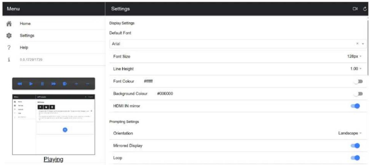
Slave Mode: When enabled the device will act as a slave screen to another dvPrompter app, please see the appropriate section of this manual for more information.
Default font: Select the default font used by the editor (this can be overridden on a per script basis using the editor).
Font Size: Sets the default font size, this will apply to all text that does not have a font size set within the editor.
Line Height: Sets the spacing between lines when scrolling, values below 1 may result in text overlapping.
Font colour: Sets the default font colour (this can be overridden on a per script basis using the editor).
Background colour: Sets the background colour.
HDMI IN mirror (TP-700/800/900 Only): Enable disable hardware mirroring on the HDMI IN port.
Orientation: Select if your device will be 'Landscape' or 'Portrait'.
Mirrored Display: Set to 'Off' if reading the text directly from the device, set to 'On' if reading the text via a mirror.
Loop: Set to 'On' to continually loop the script when finished (only valid when playlists are not in use).
Scrolling speed: Set the speed the text will start to scroll at, this can be adjusted via the hardware or network remote control.
Speed Adjustment Steps: Control how many steps the speed will be increased/decreased with every button press.
Cue marker: Optionally select a cue marker to define the line of text the talent should read.
Cue Background: Set the cue marker background colour (only valid when using plain or combined cue markers).
External Display: When disabled any second display connected via HDMI or wireless will mirror the main display, when enabled text will only scroll on the second display, the main display can be used to create and edit scripts as well as control the text.
Border: Used to add a border around the scrolling text, this is useful if the text is too close to the edge of your monitor and or beam-splitter glass.
Timer: Display a timer showing the time the text as been scrolling on screen, the timer will reset when a new script is loaded and pause when the script is paused.
Auto start: When set to 'On' the script will start scrolling automatically, when set to 'Off' the script must be started using the on-screen menu, hardware or network remote control.
Open HDMI on boot (TP-700/800/900 Only): Automatically switch to HDMI input 10 seconds after the app loads.
Start delay: Optionally set a delay (in seconds) between the start command being issued and text starting to scroll (work with manual start and auto start).
Screenshot Enabled: Enables or disabled the screenshots used for remote monitoring via the web interface.
Screenshot Delay (ms): The time in milliseconds a screenshot is taken and send to the network web interface for remote monitoring, a lower value will result in less delay but higher CPU and network usage.
Break marker: You can also set up text characters like *# that indicate a break in the scrolled text called break markers. These markers can then be used to quickly jump forward or backward between points in the text, when using the hardware or network remote control, should the running order of the production change.
Remote control: The optional Datavideo WR-500 controller can be used to control the script, please select either Bluetooth or wired mode.
Webui Access: All optionally features are already unlocked on the TP-700.
Enable Hotkeys: Allows you to assign keyboard shortcuts to the control buttons. This option can only be configured via the web interface.
Synchronizing Multiple Devices
Via HDMI
The TP-700 features HDMI input and output ports, multiple TP-700 units can be connected in a daisy chain by connecting the HDMI output of one TP-700 to the HDMI input of another. The HDMI output port is located next to the Ethernet port.
Please see the appropriate section of this manual for more information on using the HDMI input port.
Please Note: The scrolling refresh rate will be reduced when driving external displays via HDMI, you may notice a slight jitter when scrolling at higher speeds.
Via Ethernet
The feature allows you to synchronize the scrolling text on two or more TP-700s via an Ethernet network.
Requirements
- All devices must be identical for synchronization to work (devices with identical screen heights may work but this cannot be guaranteed).
- Slave devices will place additional load on the master device, the number of slave devices that can be connected is dependent on the performance of the master device.
- All slave devices must be connected to the same local network as the master device.
Setup Instructions
- The master and slave devices must all have unique IP addresses on the same network. We would recommend connecting all TP-700s to a DHCP network/router so that all devices are assigned a unique IP address automatically. Please see the appropriate section of this manual for instructions on switching the TP-700 into DHCP mode.
- Connect the supplied USB mouse
- Obtain the IP address of the master device by navigating to the network menu.
- Open the settings menu on the slave device, enable slave mode and enter the IP address of the master.

- Tap home on the menu bar, you will see the screen below while the slave establishes a connection to the master.

- Once connected the screen will turn white then black, the slave will now mirror the master.
- To exit slave mode tap the screen then press the blue exit button, the app will close.

Using the HDMI Input
The HDMI input port can be used to connect third party teleprompter software, cameras and video conferencing software.
Please Note: HDMI input is only available with firmware 140001 or above, please consult the appropriate section of this manual to check your firmware revision and update if needed.
To manually switch to the HDMI input simply click the button in the top right corner of the WebUI.
To permanently enable the HDMI input, enable the 'Open HDMI IN on boot option under the 'Settings' menu, this can be done via the WebUI or directly on the device by connecting the supplied USB mouse.
The HDMI input can also be used as part of a playlist, please see the appropriate section of this manual for more information.
Hardware Mirroring
The HDMI input port features mirroring in hardware, this allows you to use any HDMI source and ensure the image is correctly oriented on the glass. Mirroring is disabled by default, to enable mirroring simply enable the 'HDMI IN mirror' option under the 'Settings' menu.
Please Note: Hardware mirroring is only available with firmware 140001 or above, please consult the appropriate section of this manual to check your firmware revision and update if needed.
Connecting an External Display
You can connect an external display using the HDMI output on the TP-700. The HDMI output port is located next to the Ethernet port.
External Display Setting Disabled (Recommended if using webUI control)
In this mode the external display will mirror the devices screen.
External Display Setting Enabled (Recommended if using USB keyboard and mouse)
In this mode the text will only scroll on the external display leaving the device screen free for script control and editing. The script control options can be accessed via the menu bar as seen below.

External Display Rotation
By default, the internal LCD screen is rotation angle is set to 180 degrees and the external HDMI output is set to 0 degrees. This is the correct configuration for connecting multiple TP-700 units via HDM, however if using the HDMI output to connect to an external display you should set the external rotation angle to 180 degrees also.
To change this setting:
- Connect the supplied USB mouse and right click to close the dvPrompter Plus app
- Click the 'Settings' app by clicking it once
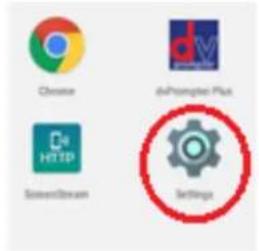
- Click 'Display' and change the setting shown below

Updating the App & Firmware
Please check the monitor's firmware is up to date and then check the app version.
Updating the Monitor Firmware
Please see the 'Firmware' under 'Downloads' here https://www.datavideo.com/global/product/TP-700 for detailed instructions on updating the monitors firmware.
Updating the App
You can download the latest App (if available) from www.datavideo.com/product/TP-700. The current App version is shown at the bottom of the menu.

- Download the latest App from www.datavideo.com/product/TP-700
- Copy the downloaded .apk file to the root directory of a USB flash drive
- Connect the USB flash drive containing the file to one of the TP-700s USB ports
- Connect the supplied USB mouse to the other USB port
- Open the 'File Manager +' App by clicking it once

- Open the USB flash drive by clicking it once

- Double click the dvPrompter Plus .apk file you downloaded earlier
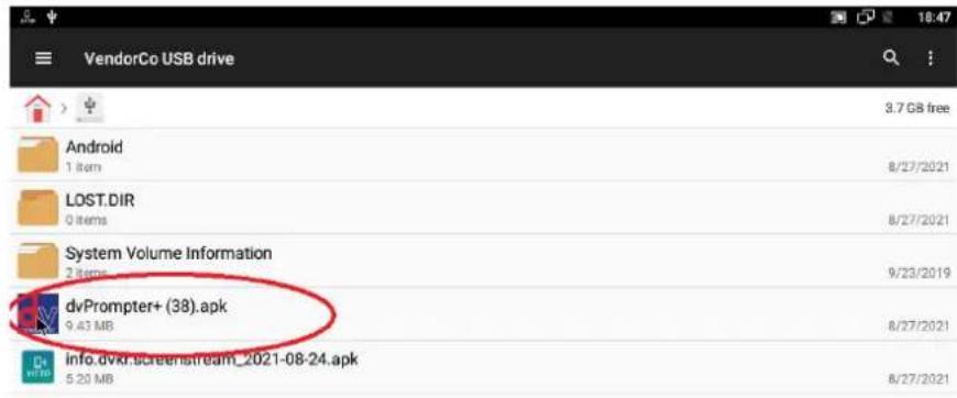
- The update will install, the dvprompter App will automatically open when complete

Specifications
| Device Used | 15" monitor with integrated dvPrompter Plus Software | |
| Multi-language Support | EnglishDutchSpanishPortugueseRussian | |
| Prompter Size (Max) | Width | 430 |
| Height | 345 | |
| Depth | 820 | |
| LCD Native Resolution | 1024 x 768 | |
| LCD Brightness | 350 NIT | |
| Remote Control | Monitoring and control via LANOptional WR-500 wired hardware remote | |
| Weight | Net Weight | 6.3 KG |
| Gross Weight | 7.8 KG | |
| Operating Temperature | 0 – 40°C | |
| Gift box size | 540x400x220 mm | |
| Power | 12V 2A DC (Mains adapter supplied)V-Lock battery | |
Notes
Service & Support
It is our goal to make owning and using Datavideo products a satisfying experience. Our support staff is available to assist you to set up and operate your system. Contact your local office for specific support requests. Plus, please visit www.datavideo.com to access our FAQ section.
Please visit our website for latest manual update.
www.datavideo.com/product/TP-700
datavideo
www.datavideo.com

@DatavideoUSA @DatavideoIndia2016
@DatavideoEMEA @Datavideojapan
@DatavideoTaiwan @DatavideoLatam
@DatavideoAsia @DatavideoBrasil

@Datavideo
@Datavideo EMEA
@Datavideo Taiwan

@DatavideoUSA
@DVTWDVCN

@DatavideoUSA
@DatavideoEurope

- CONTENTS
- FCC COMPLIANCE STATEMENT ....4
- WARNINGS AND PRECAUTIONS ....4
- WARRANTY....5
- PRODUCT OVERVIEW......8
- ASSEMBLY - TP-700 9
- CONNECT A PC/LAPTOP FOR CONTROL AND MONITORING OVER IP 15
- CAMERA EXPOSURE AND THE 70/30 MIRROR GLASS....16
- CLEANING THE 70/30 GLASS....16
- OPTIONAL TELEPROMPTER REMOTE CONTROLS....17
- DVPROMPTER PLUS APP 24
- SPECIFICATIONS 38
- SERVICE AND SUPPORT ....40
- DISCLAIMER OF PRODUCT AND SERVICES
- FCC COMPLIANCE STATEMENT
- WARNINGS AND PRECAUTIONS
- GLASS – HANDLE WITH CARE
- WARRANTY
- STANDARD WARRANTY
- REGISTER FOR 3 YEAR WARRANTY
- DISPOSAL
- FOR EU CUSTOMERS ONLY - WEEE MARKING
- PRODUCT OVERVIEW
- FEATURES
- ASSEMBLY - TP-700
- ASSEMBLY – ENG CONFIGURATION
- ASSEMBLY – FREESTANDING CONFIGURATION
- ASSEMBLY – OPTIONAL TALENT MONITOR
- CONNECT A PC/LAPTOP FOR CONTROL AND MONITORING OVER IP
- DIRECT ETHERNET CONNECTION
- CONNECTION VIA A ROUTER / DHCP LAN
- CAMERA EXPOSURE AND THE 70/30 MIRROR GLASS
- CLEANING THE 70/30 GLASS
- OPTIONAL TELEPROMPTER REMOTE CONTROLS
- WR-500 HANDHELD CONTROLLER
- REMOTE ACCESSORIES
- FS-30 FOOT SWITCH
- CONTROL BUTTONS
- GENERIC PRESENTATION CLICKERS
- CONTOUR SHUTTLE XPRESS
- SETUP
- DVPROMPTER PLUS APP
- DOCUMENTS SCREEN
- CREATING AND EDITING TEXT SCRIPTS AND SLIDES
- TEXT SCRIPTS
- SLIDES
- EXPORTING SLIDES FROM POWERPOINT
- EXPORTING SLIDES FROM KEYNOTE
- IMPORTING SLIDES
- REAL TIME EDITING
- PLAYLISTS
- ADDING A SCRIPT TO THE PLAYLIST
- ADDING HDMI IN TO THE PLAYLIST
- CHANGING THE PLAYLIST ORDER
- CONTROL
- VIA THE DEVICE (USB MOUSE)
- VIA THE WEB INTERFACE
- KEYBOARD SHORTCUTS
- USING OPTIONAL HARDWARE REMOTE CONTROLS
- MENU BAR
- SETTINGS
- SYNCHRONIZING MULTIPLE DEVICES
- VIA HDMI
- VIA ETHERNET
- REQUIREMENTS
- SETUP INSTRUCTIONS
- USING THE HDMI INPUT
- HARDWARE MIRRORING
- CONNECTING AN EXTERNAL DISPLAY
- EXTERNAL DISPLAY ROTATION
- UPDATING THE APP & FIRMWARE
- UPDATING THE MONITOR FIRMWARE
- UPDATING THE APP
- NOTES
- SERVICE & SUPPORT
Brand : DataVideo
Model : TTL-100
Category : Camera