A32 - Console audio Solid State Logic - Free user manual and instructions
Find the device manual for free A32 Solid State Logic in PDF.

User questions about A32 Solid State Logic
0 question about this device. Answer the ones you know or ask your own.
Ask a new question about this device
Download the instructions for your Console audio in PDF format for free! Find your manual A32 - Solid State Logic and take your electronic device back in hand. On this page are published all the documents necessary for the use of your device. A32 by Solid State Logic.
USER MANUAL A32 Solid State Logic
A16.D16, A32, D64 and GPIO 32
Network I/O
User Guide
Revision: 1.1
text_image
Solid Static Logic NETNO ALBERT NETNO NO Solid Static Logic NETNO NOSolid State Logic
OXFORD·ENGLAND
Visit SSL at:
www.solidstatelogic.com
© Solid State Logic
All rights reserved under International and Pan-American Copyright Conventions
SSL*, Solid State Logic*, Total Recall*, Gravity* and Tempest* are ® registered trademarks of Solid State Logic.
System T ^TM , Live L100 ^TM , Live L200 ^TM , Live L300 ^TM , Live L500 ^TM , L500 Plus ^TM , Blacklight ^TM are ^TM trademarks of Solid State Logic.
Dante™ and Audinate™ are trademarks of Audinate Pty Ltd.
All other product names and trademarks are the property of their respective owners and are hereby acknowledged.
No part of this publication may be reproduced in any form or by any means, whether mechanical or electronic, without the written permission of Solid State Logic, Oxford, OX5 1RU, England.
As research and development is a continual process, Solid State Logic reserves the right to change the features and specifications described herein without notice or obligation.
Solid State Logic cannot be held responsible for any loss or damage arising directly or indirectly from any error or omission in this manual.
PLEASE READ ALL INSTRUCTIONS, PAY SPECIAL HEED TO SAFETY WARNINGS.
E&OE
December 2019
Table of Contents
Introduction 4
Overview 4
Key Features 4
A16.D16 Front Panel 5
A16.D16 Rear Panel 5
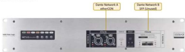
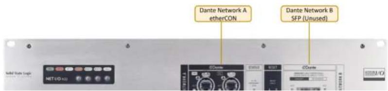
A32 Front Panel 5
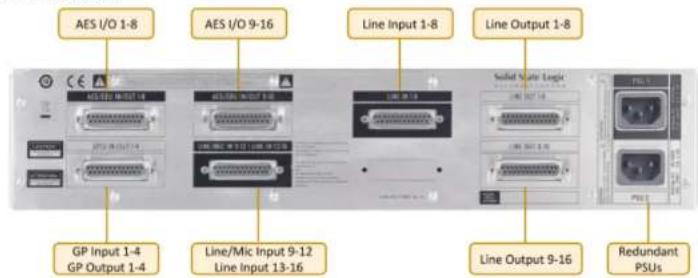
A32 Rear Panel 5
D64 Front Panel 6
D64 Rear Panel 6
GPIO 32 Front Panel 6
GPIO 32 Rear Panel 6
Status LEDs and User Buttons 7
Status and Reset 7
Device Reset 7
Brooklyn Reset 7
User and Control Bit Pass-Through
(A16.D16 and D64 Only) 8
Hardware Connections 9
Mains Power Connections 9
Dante Connections 9
Audio and GPIO Connections 9
SSL Network I/O Controller 10
Installing Network I/O Controller 10
Network Configuration - PC 10
Network Configuration - Device 10
The GUI 11
Network View 11
Inputs/Outputs 12
Appendix A - Physical Specifications 18
Ventilation 18
Appendix B - Connector Pin Outs 19
Analogue Inputs/Outputs 19
AES/EBU Inputs/Outputs 20
GPIO 21
Appendix C -
Performance Specifications 22
Mic/Line Inputs 22
Line Inputs 23
Line Outputs 23
Digital Inputs 24
Digital Outputs 24
Appendix D - Safety Notices 25
General Safety 25
Installation Notes 25
Power Safety 26
For EU 26
Environmental Declaration 27
RoHS Notice 27
For USA 27
Electromagnetic Compatibility 27
Environmental 27
Introduction
Overview
A16.D16, A32, D64 and GPIO 32 are 2U Dante I/O devices featuring high-density combinations of SuperAnalogue™, AES3 and GPIO connections. All analogue audio, AES audio and GPIO connectors are 25-pin D-type.
A16.D16, A32 and D64 can be controlled remotely from SSL System T consoles, SSL Live consoles and SSL's Network I/O Controller app for PC.
A16.D16 is a 32-input and 32-output Dante I/O device featuring 4 SuperAnalogue mic/line inputs, 12 SuperAnalogue line inputs, 8 AES3 Inputs, 16 SuperAnalogue line outputs, 8 AES3 outputs and 4 GPIO connections.
A32 is a 32-input and 32-output Dante I/O device featuring 32 SuperAnalogue line inputs and 32 SuperAnalogue Line outputs.
D64 is a 64-input and 64-output Dante I/O device featuring 32 AES3 inputs and 32 AES3 outputs.
These units are ideally suited for bulk analogue and AES I/O connections from control or machine rooms, featuring a high-density combination of analogue and digital inputs and outputs, GPIO, redundant power and network connections.
GPIO 32 is a 32-input and 32-output GPIO device which connects over a Dante network and can be controlled remotely from SSL System T consoles. It facilitates a variety of possibilities and applications for System T consoles, such as custom user key panels or complex Audio Follow Video setups. When coupled with System T's powerful Event Manager, GPIO 32 has endless possibilities for custom console functions and external triggers.
Key Features
- Interface between control/machine room analogue/AES connections and IP audio networks using Dante and AES67
- Redundant PSUs and Dante network connections
- SSL SuperAnalogue technology
• Device and parameter ownership assignment to avoid control conflicts
• Front facing Dante network connections
A16.D16, A32, D64 and GPIO 32 User Guide
Contents
A16.D16 Front Panel
text_image
Dante Network A etherCON Dante Network B SFP (Unused) NET1/O 4.000000 NET1/O 4.000000 NET1/O 4.000000 NET1/O 4.000000 NET1/O 4.000000 NET1/O 4.000000 NET1/O 4.000000 NET1/O 4.000000 NET1/O 4.00A16.D16 Rear Panel
text_image
AES I/O 1-8 AES I/O 9-16 Line Input 1-8 Line Output 1-8 Solid State Logic GP Input 1-4 GP Output 1-4 Line/Mic Input 9-12 Line Input 13-16 Line Output 9-16 Redundant PSUsA32 Front Panel
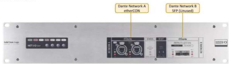
text_image
Dante Network A etherCON Dante Network B SFP (Unused)A16.D16, A32, D64 and GPIO 32 User Guide
Contents
D64 Front Panel
text_image
Dante Network A etherCON Dante Network B SFP (Unused)D64 Rear Panel

text_image
AES I/O 1-8 AES I/O 9-16 AES I/O 17-24 AES I/O 25-32 Solid State Logic AES I/O 33-40 AES I/O 41-48 AES I/O 49-56 AES I/O 57-64 Redundant PSUsGPIO 32 Front Panel

text_image
Dante Network A etherCON Dante Network B SFP (Unused)Status LEDs and User Buttons

text_image
Green - normal operation, both power supplies active Red (solid) - primary power supply inactive Red (flashing) - secondary power supply inactive Off - normal operation Orange - indicates a fault has occurred, refer to the setup information window If RESET A is pressed for 6 seconds then the primary Dante network connection will reset to use DHCP - the RESET A LED will briefly light yellow then the unit must be rebooted If RESET A and HOLD are pressed for 6 seconds this will perform a device reset - the RESET A LED will flash twice then the unit must be rebooted PSU NET A NET B STATUS RESETA RESETB HOLD NET I/O A16.D16 Not used Green - Dante primary and secondary network connection active Red (solid) - Dante primary network connection fault Red (flashing) - Dante secondary network connection faultStatus and Reset
These reset buttons have the same functionality as the front-facing RESET A and RESET B user buttons.

text_image
STATUS LED functionality is If RESET A is held for 6 seconds then the primary Dante network connection will reset to use DHCP - the RESET A LED will briefly light yellow then the unit must be rebooted If RESET A and RESET B are pressed for 6A16.D16, A32, D64 and GPIO 32 User Guide
Contents
User and Control Bit Pass-Through (A16.D16 and D64 Only)
To enable the pass-through of AES user and control bits the device must be set to PCM 32 encoding within Dante Controller. Changing the encoding setting is detailed in the Dante Controller section of this guide.
N.B. When set to 32-bit encoding the audio remains 24-bit. The additional 8 bits are used to transport the user and control bits from the AES3 signals.
A16.D16, A32, D64 and GPIO 32 User Guide
Contents
Hardware Connections
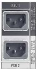
Mains Power Connections
The A16.D16, A32, D64 and GPIO 32 include redundant PSUs with IEC C14 inlets. Either supply can individually power the unit. Ideally these should be connected to separate power circuits to provide redundancy of incoming AC power.
Dante Connections

text_image
Network A ports feature etherCON ruggedised RJ45 connectors Network B ports are SFP cages which can be fitted with either RJ45, single-mode or multi-mode LC fibre connectors Note: Network B functionality is currently not enabled A pair of LEDs per port provide network information: ACT flashes when there is network activity GB/SFP shows Ethernet/SFP network statusThe A16.D16, A32, D64 and GPIO 32 have two redundant sets of network connections. The Network B port connectivity is currently not enabled, this requires an additional Dante card which is currently not available.
Audio and GPIO Connections
All audio and GPIO connections are via 25-pin D-type connectors.
LINE IN 1-8
SSL Network I/O Controller
This section applies to the A16.D16, A32 and D64 only. GPIO 32 cannot be controlled from SSL Network I/O Controller.
Installing Network I/O Controller
When an A16.D16, A32 or D64 is used without an SSL console, configuration and control is achieved using the SSL Network I/O Controller PC application. This can be downloaded from the SSL website as part of the Network I/O Stagebox upgrade package or as a standalone installer.
Locate and run the Network I/O Controller installer and follow the on-screen prompts to install the application.
Network Configuration - PC
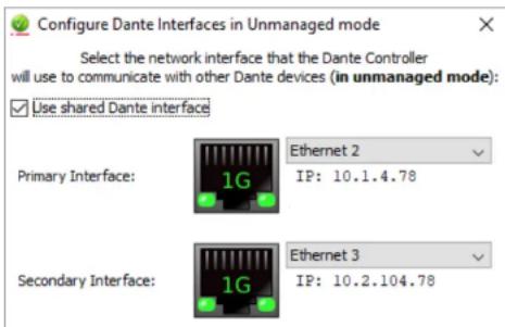
Once Network I/O Controller is installed, connect the Windows PC to the same subnet as the Network I/O. The SSL Network I/O Controller application uses the network adapters configured in Dante Controller for communication. Before starting Network I/O Controller first open Dante Controller and select the network adaptors connected to the Dante network. 'Use shared Dante interface' must be selected to ensure all applications using the Dante network use the correct adaptors. Subsequent changes to network settings may require Network I/O Controller to be restarted.
text_image
Configure Dante Interfaces in Unmanaged mode Select the network interface that the Dante Controller will use to communicate with other Dante devices (in unmanaged mode): ✓ Use shared Dante interface Primary Interface: 1G Ethernet 2 IP: 10.1.4.78 Secondary Interface: 1G Ethernet 3 IP: 10.2.104.78The GUI
The application window is divided into six sections:
Input meters are shown for every analogue input. The D64 is displayed as a narrow device with no input metering.
Network View shows each SSL device on the Dante network. Clicking a device brings its parameters into the Detail View. Large arrows on the far left and right scroll for more devices.
Detail View shows channel details for the selected device. Large arrows on the far left and right scroll for more channels.
Focus View shows an expanded view of the selected channel.
text_image
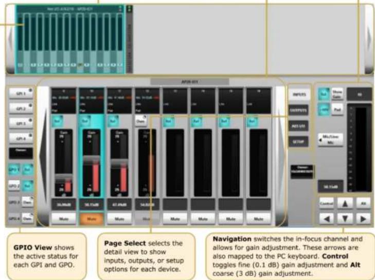
GPIO View shows the active status for each GPI and GPO. Page Select selects the detail view to show inputs, outputs, or setup options for each device. Navigation switches the in-focus channel and allows for gain adjustment. These arrows are also mapped to the PC keyboard. Control toggles fine (0.1 dB) gain adjustment and Alt coarse (3 dB) gain adjustment.Inputs/Outputs
Select the Inputs, Outputs or AES I/O tab in the Page Select area to view I/O available on the network.
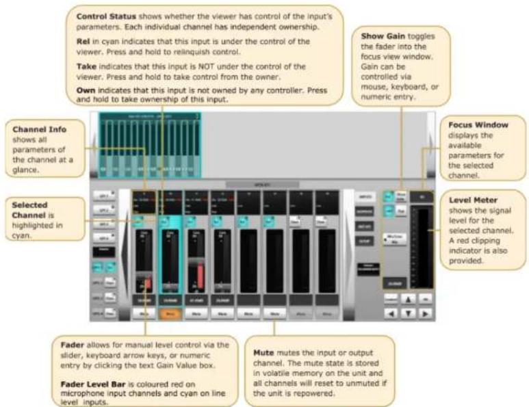
Analogue Inputs
This applies to the A16.D16 and A32 only.
text_image
Control Status shows whether the viewer has control of the input's parameters. Each individual channel has independent ownership. Rel in cyan indicates that this input is under the control of the viewer. Press and hold to relinquish control. Take indicates that this input is NOT under the control of the viewer. Press and hold to take control from the owner. Own indicates that this input is not owned by any controller. Press and hold to take ownership of this input. Show Gain toggles the fader into the focus view window. Gain can be controlled via mouse, keyboard, or numeric entry. Channel Info shows all parameters of the channel at a glance. Selected Channel is highlighted in cyan. Focus Window displays the available parameters for the selected channel. Level Meter shows the signal level for the selected channel. A red clipping indicator is also provided. Fader allows for manual level control via the slider, keyboard arrow keys, or numeric entry by clicking the text Gain Value box. Fader Level Bar is coloured red on microphone input channels and cyan on line level inputs. Mute mutes the input or output channel. The mute state is stored in volatile memory on the unit and all channels will reset to unmuted if the unit is repowered.A16.D16, A32, D64 and GPIO 32 User Guide
Contents
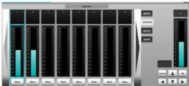
Analogue Outputs
This applies to the A16.D16 and A32 only.
text_image
AUTO-021 INPUTS OUTPUTS AUTO ON STOP AUTO AUTO AUTO AUTO AUTO AUTO AUTO AUTO AUTO AUTO AUTO AUTO AUTO AUTO AUTO AUTO AUTO AUTO AUTO AUTO AUTO AUTO AUTO AUTO AUTO AUTO AUTO AUTO AUTO AUTO AUTO AUTO AUTO AUTO AUTO AUTO AUTO AUTO AUTO AUTO AUTO AUTO AUTO AUTO AUTO AUTO AUTO AUTO AUTO AUTO INTU INTU INTU INTU INTU INTU INTU INTU INTU INTU INTU INTU INTU INTU INTU INTU INTU INTU INTU INTU INTU INTU INTU INTU INTU INTU INTU INTU INTU INTU INTU INTU INTU INTUMute allows individual outputs to be muted
AES I/O
This applies to the A16.D16 and D64 only.
Control Status shows whether the viewer has control of the input's parameters. Each individual channel has independent ownership.
Rel in cyan indicates that this input is under the control of the viewer. Press and hold to relinquish control.
Take indicates that this input is NOT under the control of the viewer. Press and hold to take control from the owner.
Own indicates that this input is not owned by any controller. Press and hold to take ownership of this input.

text_image
SRC In enables SRC for the in-focus input channelsGPIO
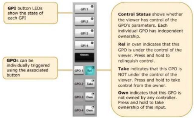
This applies to the A16.D16 only. The A16.D16 is equipped with 4 GP input and 4 GP output circuits. Inputs are opto-isolated voltage triggered and output closures are via DIL relay.
See Appendix B for connector pinout and contact ratings.
text_image
GPI button LEDs show the state of each GPI GPOs can be individually triggered using the associated button GPI 1 GPI 2 GPI 3 GPI 4 Owner: GPO 1 GPO 2 GPO 3 Owner: Control Status shows whether the viewer has control of the GPO's parameters. Each individual GPO has independent ownership. Rel in cyan indicates that this GPO is under the control of the viewer. Press and hold to relinquish control. Take indicates that this GPO is NOT under the control of the viewer. Press and hold to take control from the owner. Own indicates that this GPO is not owned by any controller. Press and hold to take ownership of this input.Setup
Press Setup in the Page Select area to display the system configuration information.
Stagebox Ownership and Inputs Ownership are detailed under Ownership.

flowchart
graph LR
    A["Name shows the device name as set in Dante Controller."] --> B["Info shows the status of the device's redundant power supplies, fans, and temperature. Red indicates a fault."]
    B --> C["Operating Level allows selection of the maximum analogue I/O level in dBu (at 0dBFS) for the device."]
Ownership
Ownership offers a level of protection to Inputs: when an input is owned by a console the input parameters can only be modified by the device that owns it. This prevents control conflicts between networked consoles and control computers sharing resources. Parameters covered by ownership are:
- Mic gain
- Mic/line switching
- Pad
- Input mute
• SRC
Note that multiple consoles can share the same input signal but only one device can control the input parameters. Altering the input settings will affect all consoles using the input.
Any System T console, SSL Live console or instance of the SSL Network I/O Controller PC application can control ownership. There are three levels of ownership:
- Stagebox ownership: control A16.D16/A32/D64 setup Information only
- Input ownership: control input parameters only
- Input x ownership: control of input parameters on a per input basis
N.B. Ownership settings are stored on the A16.D16/A32/D64. The mute state is stored in volatile memory on the unit and all channels will reset to unmuted if the unit is repowered.
Stagebox and Input Ownership

text_image
Press and hold Stagebox Ownership to assign or relinquish stagebox ownership If a unit is owned then the operating level can be changedIndividual Input Ownership
One of three options will be displayed when an input is selected on a device, depending on the current ownership state. These options are Own, Take and Release:

text_image
Inputs owned by another controller have a press and hold Take button and show the owner Unowned inputs have a press and hold Own button and show there is no owner 40.00dB Gain 70 20 dB Mute 53.22dB Gain 70 20 dB Mute 38.04dB Gain 70 20 dB Mute Only mic inputs owned by this device have a fader cap and can be controlledWhen an SSL console makes routes from Stagebox inputs, the console will automatically become the owner of any unowned Inputs. If an input is owned by a different controller then routing will not automatically take ownership, Take ownership will need to be performed if input control is required on this device. Ownership from Network I/O Controller is manually controlled.
Note that the audio route will still be made regardless of whether ownership is assigned.
Dante Controller

text_image
Dante Controller - Network View File Device View Help Grund Master Clock: AP20-IO1 Routing Device Info Clock Status Network Status Events Device Name Product Type Product Version Dante Version Device Lock Primary Address Primary Link Speed Secondary Address Secondary Link Speed AP20-IO1 NETWORK I/O A16.D16 1.0.0 3.10.1.2 10.20.1.1 1Gbps Link down P: S: Unmanaged Multicast Bandwidth: 0 bps Event Log: Clock Status Monitor:Refer to Audinate's Dante Controller user guide for complete information on Dante Controller software. The information below details the basics required to get started.
Clock sync, device naming, AES67 configuration and network management are all done within Dante Controller.
Dante utilises the device name for routing. Each device must have a unique name – if a name is duplicated it will be appended with a number.
Network Config
Each device requires its own unique IP address. This may be automatically configured, provided by a DHCP server or assigned manually. The primary and secondary ports must not be connected to the same logical network. Ideally, separate switching hardware should be provided for primary and secondary networks. Creating VLANs on shared hardware is acceptable but does not provide the most robust redundancy.
Device Info
The Device Info tab shows an overview of all devices on the Dante network including name, product type, software version, IP address, link speed and status.
Appendices
Appendix A – Physical Specifications
| Parameter | Value | Notes |
| Depth | 460 mm (18.11") | |
| Height | 88.5 mm (1.75") | 2 RU |
| Width | 438 mm (17.25")482 mm (19") | Excluding rack earsIncluding rack ears |
| Weight | 9.5 kg (21 lb) | |
| Power | < 100 W | |
| Boxed Size | 538 x 538 x 228 mm (21.2 x 21.2 x 9.0") | |
| Boxed Weight | 12.5 kg (27.6 lbs) |
Ventilation
Ventilation is from the side and top of the unit.
1RU of ventilation must be provided above each unit.
Appendix B - Connector Pin Outs
| Analogue Inputs/Outputs | ||
| Location: Rear Panel | ||
| Connector Type: 25-way D-type female | ||
| Pin | Description | Notes: |
| 1 | Channel 8 (+ve) | Same circuit arrangement for Inputs and Outputs. Circuits offset by 8 for each additional connector. |
| 14 | Channel 8 (−ve) | |
| 2 | 0V | |
| 15 | Channel 7 (+ve) | |
| 3 | Channel 7 (−ve) | |
| 16 | 0V | |
| 4 | Channel 6 (+ve) | |
| 17 | Channel 6 (−ve) | |
| 5 | 0V | |
| 18 | Channel 5 (+ve) | |
| 6 | Channel 5 (−ve) | |
| 19 | 0V | |
| 7 | Channel 4 (+ve) | |
| 20 | Channel 4 (−ve) | |
| 8 | 0V | |
| 21 | Channel 3 (+ve) | |
| 9 | Channel 3 (−ve) | |
| 22 | 0V | |
| 10 | Channel 2 (+ve) | |
| 23 | Channel 2 (−ve) | |
| 11 | 0V | |
| 24 | Channel 1 (+ve) | |
| 12 | Channel 1 (−ve) | |
| 25 | 0V | |
| 13 | n/c | |
Connectors Viewed From Wiring Side
| AES/EBU Inputs/Outputs | ||
| Location: Rear Panel | ||
| Connector Type: 25-way D-type female | ||
| Pin | Description | Notes: |
| 1 | Out channels 7/8 + | Outputs. |
| 14 | Out channels 7/8 - | Circuits offset by 8 for each additional connector. |
| 2 | Ground | |
| 15 | Out channels 5/6 + | |
| 3 | Out channels 5/6 - | |
| 16 | Ground | |
| 4 | Out channels 3/4 + | |
| 17 | Out channels 3/4 - | |
| 5 | Ground | |
| 18 | Out channels 1/2 + | |
| 6 | Out channels 1/2 - | |
| 19 | Ground | |
| 7 | In channels 7/8 + | Inputs. |
| 20 | In channels 7/8 - | Circuits offset by 8 for each additional connector. |
| 8 | Ground | |
| 21 | In channels 5/6 + | |
| 9 | In channels 5/6 - | |
| 22 | Ground | |
| 10 | In channels 3/4 + | |
| 23 | In channels 3/4 - | |
| 11 | Ground | |
| 24 | In channels 1/2 + | |
| 12 | In channels 1/2 - | |
| 25 | Ground | |
| 13 | n/c | |
Connectors Viewed From Wiring Side
A16.D16, A32, D64 and GPIO 32 User Guide
Contents
GPIO
GP Outputs
All output switch closures are via DIL relay.
DO NOT use these outputs to directly switch capacitive or reactive loads; always use a separate external relay with suitable contact rating.
DIL Relay Ratings:
- 100V DC, 125V AC
- 100mA max.
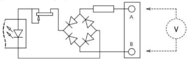
GP Inputs
Inputs are triggered by applying an AC or DC voltage of between 4V and 24V. The current drawn is approximately 10mA. Minimum input pulse duration 50mS.
text_image
Electrical circuit diagram with diodes, resistors, and a voltmeter labeled A and B| GP Inputs / Outputs | ||
| Connector Type: 25-way D-type male | ||
| Pin | Description | Notes: |
| 1 | Input 1A | See input requirements above |
| 14 | Input 1B | |
| 2 | Input 2A | Same circuit arrangement for Inputs and Outputs |
| 15 | Input 2B | Circuits offset by 4 for connectors 2 - 8 on GPIO 32 |
| 3 | Input 3A | |
| 16 | Input 3B | |
Appendix C – Performance Specifications
| Mic/Line Inputs | ||
| Parameter | Value | Notes |
| Gain Range | +26 to +70 dB-4 to +30 dB-4 to +40 dB | Mic mode, 0 dBFS, 0.1 dB gain step sizeLine mode, 0 dBFS, 0.1 dB gain step sizeMic mode with pad engaged |
| Maximum Input Level | +27.5 dBu | 30 dB Pad inserted |
| Frequency Response | ± 0.2 dB | Mic mode, 20 Hz - 20 kHz (@48kHz)Typically ± 0.1 dB |
| Equivalent Input Noise | < -123 dB | Mic mode, 70 dB gain, A-weighted filter, 22 kHz bandwidth.Typically -124 dB |
| Usable Dynamic Range | > 115 dB | Mic mode, 0 dBFS, A-weighted filter, 22 kHz bandwidth.Typically 116 dB. |
| Input Impedance | 2.3 kΩ / 10 kΩ | Mic / Line. Selectable per channel |
| CMRR | > 70 dB> 90 dB | Mic mode, 20 Hz - 20 kHz, 0 dBuMic mode, 1 kHz, 0 dBu |
| Crosstalk | > -75 dB> -90 dB | 20 Hz - 20 kHz1 kHz |
| THD+N | < 0.01 % | Mic mode, 20 Hz - 20 kHz, -1 dBFS, 22 kHz bandwidth. |
| Line Inputs | ||
| Parameter | Value | Notes |
| Maximum Input Level | +24 dBu | 10 kΩ load |
| Frequency Response | ± 0.1 dB | -1 dBFS, 20 Hz - 20 kHz |
| Usable Dynamic Range | >116 dB | 0 dBFS, A-weighted filter, 22 kHz bandwidth Typically >117 dB |
| THD+N | < 0.005 % | 20 Hz - 20 kHz, -1 dBFS, 22 kHz bandwidth Typically < 0.004% |
| Sample Rates | 44.1, 48, 88.2 or 96 kHz | |
| Resolution | 24 blt | |
| Line Outputs | ||
| Parameter | Value | Notes |
| Maximum Output Level | +24 dBu | 600 Ω / 10 kΩ load |
| Output Impedance | < 50 Ω | |
| Frequency Response | ± 0.3 dB | -1 dBFS, 20 Hz - 20 kHz |
| Usable Dynamic Range | > 116 dB | 0 dBFS, A-weighted filter, 22 kHz bandwidth |
| Digital Inputs | ||
| Parameter | Value | Notes |
| Input Impedance | 110 Ω | Transformer coupled |
| Sample Rates | 44.1, 48, 88.2 or 96 kHz | 176 kHz or 192 kHz with sample rate converters enabled |
| Sample Rate converters | Yes | Selectable per AES channel pair |
| Resolution | 24 bit | |
| Digital Outputs | ||
| Parameter | Value | Notes |
| Output Impedance | 110 Ω | Transformer coupled |
| Sample Rates | 44.1, 48, 88.2 or 96 kHz | |
| Resolution | 24 bit | |
Appendix D - Safety Notices
General Safety
- Please read and keep this document.
- Adhere to all warnings and follow instructions.
- This electrical equipment should not be used near water.
- Cleaning should only be with dry cloths or products compatible with electrical devices – never when the unit is powered.
- Keep the unit free of dust and use in a clean environment.
- Do not use near any heat source or in direct sunlight.
- Do not use near naked flames.
- Do not place heavy objects on the unit.
- Only use attachments/accessories recommended by the manufacturer.
-
Unplug the device during lightning storms or long periods of nonuse.
-
The unit can only be serviced by qualified personnel – Seek immediate service if:
I. The unit has been exposed to moisture
II. The unit has been dropped
III. The unit does not operate normally
-
Do NOT modify this unit – alterations may affect performance, safety and/or International compliance standards.
-
SSL does not accept liability for damage caused by maintenance, repair or modification by unauthorised personnel.
Installation Notes
- When installing this apparatus either fix it into a standard 19" rack or place the apparatus on a common level surface.
Power Safety
- The unit is not supplied with a mains lead allowing you to use IEC distribution of mains cables of your choice. Any mains cable used must fulfill the following:
I. Refer to the ratings label on the rear of the unit and always use suitable mains cords.
II. The unit should ALWAYS be earthed with the earth on both IEC sockets (when both are used).
III. Please use a compliant 60320 C13 TYPE SOCKET. When connecting to supply outlets ensure that appropriate sized conductors and plugs are used to suit local electrical requirements.
IV. Maximum cord length should be 4.5m (15').
V. The cord should bear the approval mark of the country in which it is to be used. - The appliance coupler is used as the disconnect device, ensure that it is connected to an unobstructed wall outlet.
- The unit is designed for connection to single phase supplies only.
- The clear markings regarding redundant power supplies detailed on the unit must be transferred into the installation to ensure both power sources are removed before qualified personnel service the unit.
GB The apparatus shall be connected to mains socket outlets with a protective earthing connection
ATTENTION! This equipment must be Earthed. Refer to manual for installation instructions.
Environmental Declaration

The symbol shown here, which is on the product or its packaging, indicates that this product must not be disposed of with other waste. Instead, it is the user's responsibility to dispose of their waste using a designated collection point for recycling of waste electrical and electronic equipment. The separate collection and recycling of your waste equipment at the time of disposal will help to conserve natural resources and ensure that it is recycled in a manner that protects human health and the environment. For more
information about where you can dispose of your waste equipment for recycling, please contact your local city office, your household waste disposal service or where you purchased the product.
RoHS Notice
Solid State Logic has conformed and this product has conformed to European Union's Directive 2011/65/EU on Restrictions of Hazardous Substances (RoHS) as well as the following sections of California law which refer to RoHS, namely sections 25214.10, 25214.10.2, and 58012, Health and Safety Code; Section 42475.2, Public Resources Code.
For USA
To the User:
- Do not modify this unit! This product, when installed as indicated in the instructions contained in the installation manual, meets FCC requirements.
- Important: This product satisfies FCC regulations when high quality shielded cables are used to connect with other equipment. Failure to use high quality shielded cables or to follow the installation instructions may cause magnetic interference with appliances such as radios and televisions and will void your FCC authorisation to use this product in the USA.
- Note: This equipment has been tested and found to comply with the limits for a Class A digital device, pursuant to part 15 of the FCC Rules. These limits are designed to provide reasonable protection against harmful interference when the equipment is operated in a commercial environment. This equipment generates, uses, and can radiate radio frequency energy and, if not installed and used in accordance with the instruction manual, may cause harmful interference to radio communications. Operation of this equipment in a residential area is likely to cause harmful interference in which case the user will be required to correct the interference at his own expense.