Native Drumstrip - Processor Solid State Logic - Free user manual and instructions
Find the device manual for free Native Drumstrip Solid State Logic in PDF.

| Product Type | Audio Processor (Drum Mixing Plugin) |
| Developer | Solid State Logic |
| Platform Compatibility | Windows 7+ / macOS 10.12+ |
| Plugin Formats | AAX, AU, VST2, VST3 |
| Bit Depth Support | 32-bit and 64-bit |
| Sample Rate Support | Up to 192 kHz |
| Key Processing Modules | Drum Gate, Drum Transient, Drum Buss, Drum Reverb, Drum LF (Low Frequency) |
| Drum Gate Features | Threshold, Attack, Hold, Release, Lookahead, Sidechain filter |
| Drum Transient Features | Attack and Sustain controls with visual display |
| Drum Buss Features | Compressor with ratio, threshold, attack, release, and mix control |
| Drum Reverb Features | Room size, decay, predelay, damp, and mix control |
| Drum LF Features | Frequency selection, boost/cut, and resonance |
| Global Controls | Input/Output gain, mix (wet/dry), bypass |
| Preset Management | Factory presets and user save/load |
| System Requirements (Windows) | Intel/AMD processor, 4 GB RAM, 1 GB free disk space |
| System Requirements (macOS) | Intel/Apple Silicon, 4 GB RAM, 1 GB free disk space |
| License Type | iLok 2/3 or machine authorization |
Frequently Asked Questions - Native Drumstrip Solid State Logic
User questions about Native Drumstrip Solid State Logic
0 question about this device. Answer the ones you know or ask your own.
Ask a new question about this device
Download the instructions for your Processor in PDF format for free! Find your manual Native Drumstrip - Solid State Logic and take your electronic device back in hand. On this page are published all the documents necessary for the use of your device. Native Drumstrip by Solid State Logic.
USER MANUAL Native Drumstrip Solid State Logic
May 2018 Software Release V6.o.o
September 2018 Software Release V6.1.0
December 2018 Software Release V6.2.0
July 2019
Software Release V6.3.0
January 2019 Software Release V6.4.0
October
2020
Software Release V6.5.0
Contents
Introduction 1
Welcome to the World of SSL 1
About This Manual 1
About the SSL Plug-In Range 2
Channel Strip 2
Bus Compressor 2
X-Comp 3
X-EQ 2 4
Vocalstrip 5
Drumstrip 6
X-ValveComp 7
X-Saturator 8
X-Phase 9
FlexVerb 10
1. Software Setup 11
System Requirements 11
Windows 11
Mac 11
Buying Plug-ins 12
SSL Webstore 13
Activating Plug-in Licenses 14
Installing the Software (Mac) 15
Installing the Software (Windows) 16
Logic Essentials - Mac Only 17
2. Channel Strip 18
Introduction 18
Interface Techniques 19
Input Section 19
Equaliser Section 20
Dynamics Section 21
Compressor/Limiter 21
Expander/Gate 21
Dynamics Values 22
Side-chain Processing Order 22
Channel Processing Order 22
Output Section 22
Input and Output Metering 23
Presets 23
A-B Comparisons 23
3. Bus Compressor 24
Introduction 24
Interface Techniques 24
Control Parameters 24
Presets 25
A-B Comparisons 25
4. X-Comp 26
Introduction 26
Interface Techniques 26
Automation 26
Control Parameters 27
Plug-in Bypass 27
Knee 27
Max GR 27
Bleed
Auditioning Bleed Bands 28
Compressor Values 28
Input and Output Sections 29
Compression Law Graph 29
Bleed Graph 29
I/O Difference Graph 29
GR History 29
Presets
A-B Comparisons 30
5. X-EQ 2 31
Introduction
Interface Overview 31
EQ Parameter Values 35
Input and Output Sections 35
Interface Techniques 36
Automation
Plug-in Bypass 36
Presets
A-B Comparisons 36
Parallel
EQ and Filter Shapes (Classic curves)
Bell Shapes
Shelving Bands
Filter Shapes
EQ History
An Audio Engineer's Best Friend
The Best of the Analogue and Digital Worlds
Analogue Parametric EQ Modelling
Input and Output Sections
Vocalstrip Modules
De-esser
Equaliser
Compander
Processing Order
7. Drumstrip
Introduction
Interface Overview
Plug-in Bypass
Automation
Presets
A-B Comparisons 48
Automation
Input and Output Sections
Drumstrip Modules
Gate
Transient Shaper
HF and LF Enhancers
28
30
31
36
36
37
39
39
40
40
41
41
41
41
42
43
43
43
43
[Non-Text]
44
44
44
44
45
46
46
47
47
47
47
47
48
48
48
49
49
49
50
Listen Mic Compressor 51
Processing Order 51
8. X-ValveComp 52
Introduction 52
Interface Overview 52
Automation 52
Plug-in Bypass 53
Presets 53
A-B Comparisons 53
Input and Output Levels 53
Knee 54
Valve In 54
Side-chain 54
Mix 54
Auto Gain 54
9. X-Saturator 55
Introduction 55
Interface Overview 55
Automation 55
Plug-in Bypass 55
Input and Output Levels 56
Boost +6dB 56
Drive 56
Harmonics 56
Depth / Shape 56
Presets 57
A-B Comparisons 57
10. X-Phase 58
Introduction 58
Interface Overview 58
Automation 58
Plug-in Bypass 58
Input and Output Levels 59
Delay 59
All-pass In 59
All-pass Phase 59
Frequency 59
Second Order 59
Q Factor 59
Stereo Version 59
Presets 60
A-B Comparisons 60
Phased by Phase? 61
The All-pass Filter Idea 62
11. FlexVerb
Introduction 63
Interface Overview 63
Automation 63
Plug-in Bypass 63
Presets 64
A-B Comparisons 64
Early Reflections and Reverb Tail Selection 65
Reverb Tail Control Section 65
3-Band Reverb Time Multipliers 65
6-Band EQ 65
Input Side-Chain Compressor 66
Mix 66
Introduction
WELCOME TO THE WORLD OF SSL
Congratulations on purchasing SSL's Native plug-ins. SSL Native delivers the full SSL mix experience via a comprehensive suite of DAW plug-ins for your computer, including powerful channel and dynamics processing, the legendary Stereo Bus Compressor, plus a variety of contemporary audio tools developed to provide you with extensive processing versatility.
SSL Native is the result of our unique understanding of SSL's sonic heritage coupled with years of DSP development.
ABOUT THIS MANUAL
This manual starts with a complete overview of the processes involved to install and authorise your plug-ins, then goes into a detailed description of all of the plug-ins in the SSL Native range.
Please note that the procedures involved in loading and using plug-ins within your host application are not covered in this manual. Please refer to your host application's user guide for more information on how to use plug-ins in general.
ABOUT THE SSL PLUG-IN RANGE
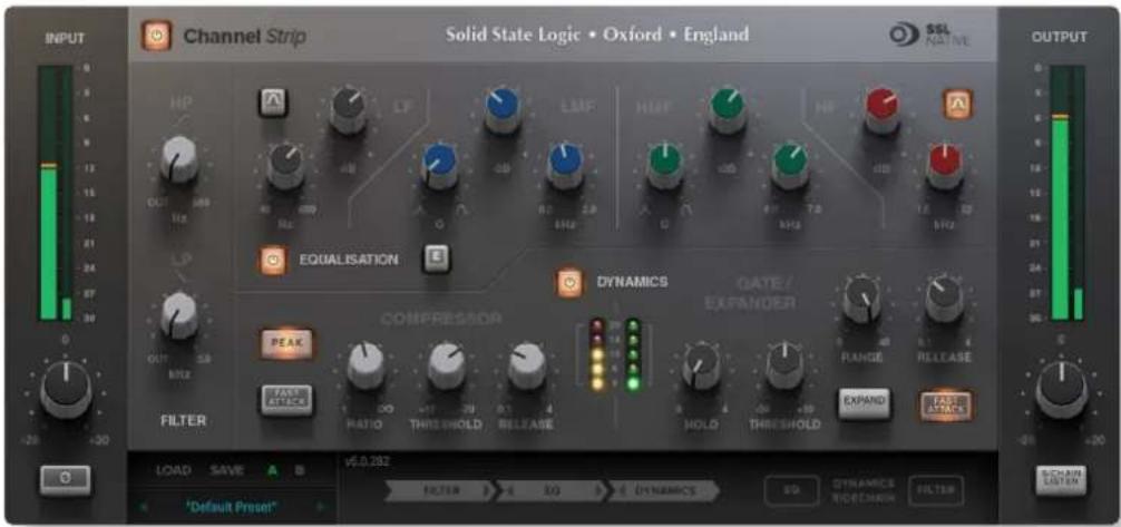
Channel Strip
SSL were the first mixing console manufacturer to feature dynamics and EQ on every channel on an in-line console with the SSL 4000 B Series in 1977. The Channel Strip plug-in is based on the EQ and dynamics sections of SSL's analogue consoles. The plug-in includes separate high and low pass filters, an independent compressor/limiter and gate/expander, a four-band parametric equaliser that is assignable to the dynamics side-chain, variable processing order as well as input and output gain adjustment and phase inversion.
text_image
INPUT Channel Strip Solid State Logic • Oxford • England SISL NATIEM OUTPUT HP LF LMF HMF HF EQUALISATION E DYNAMICS QATE / EXPANDER RANGE RELEASE PEAK FAST ATTACK FILTER RATIO THRESHOLD RELEASE HOLD THRESHOLD EXPAND LAST ATTACK LOAD SAVE A B V6.0.292 FILTER >> 4 50 > DYNAMICS 50 DYNAMICS RECORDER FILTER *Default Preset*Bus Compressor
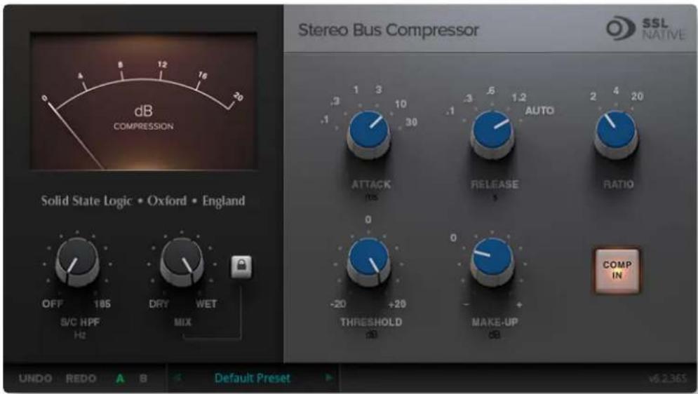
The Bus Compressor plug-in is based on the legendary centre section bus compressor found on SSL's large-format analogue consoles. It provides high quality stereo compression, giving you critical control over the dynamic range of audio signals.
text_image
dB COMPRESSION Solid State Logic • Oxford • England OFF 18S DRY WET S/C HPF MIX SIDE DO REDO A B Default Preset Stereo Bus Compressor SSL NATIVE AUTO RATIO COMP IN ATTACK 0 -20 +20 THRESHOLD 0 MAKE-UP dBUses may include inserting the bus compressor over a stereo mix, which has the effect of 'gluing' the mix together whilst still maintaining a big sound. The dynamics of drum overheads or whole drum kits can be controlled very effectively with the bus compressor. As it is available as either a stereo or mono plug-in the bus compressor can be used for practically any application that requires superior compression.
X-Comp
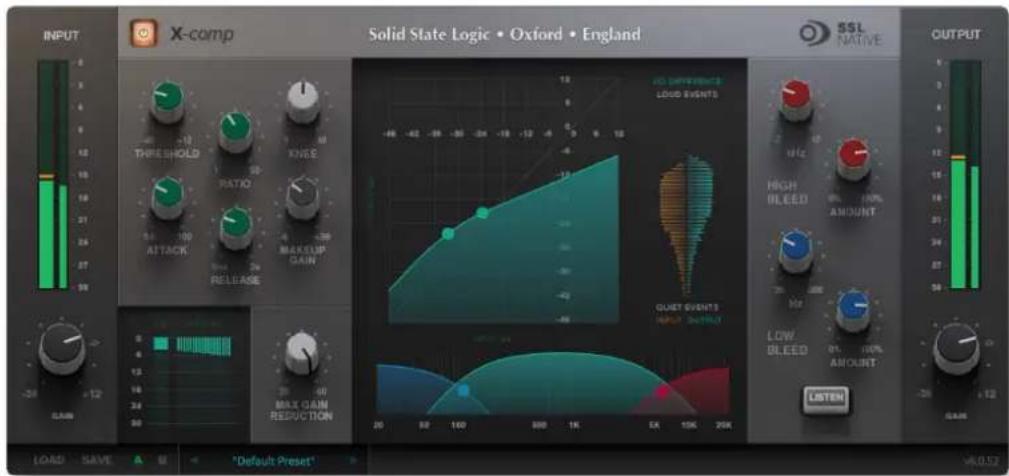
X-Comp can deliver the transparent audio finesse of a mastering-grade stereo compressor or be driven to inject character and raw power to rival the SSL Listen Mic Compressor. In X-Comp we haven't just modelled a particular compressor, but have provided a set of features and controls that allow the emulation of many vintage and modern compression designs based on a well-loved SSL feed forward compressor algorithm.
text_image
INPUT X-comp Solid State Logic • Oxford • England SSL NATIVE OUTPUT LOAD SAVE *Default Preset* 12 13 14 15 16 17 18 19 20 21 22 23 24 25 26 27 28 29 30 31 32 33 34 35 36 37 38 39 40 41 42 43 44 45 46 47 48 49 50 51 52 53 54 55 56 57 58 59 60 61 62 63 64 65 66 67 68 69 70 71 72 73 74 75 76 77 78 79 80 81 82 83 84 85 86 87 88 89 90 91 92 93 94 95 96 97 98 99 100 101 102 103 104 105 106 107 108 109 110 111 112Key Features
- Dual-symmetrical knee design allows detailed shaping of the compression characteristic.
- Advanced side-chain architecture using 1st order filters delivers user-friendly frequency dependant parallel compression.
- Amplitude Histogram and Gain Reduction history displays provide advanced real-time pre/post signal analysis.
- Max Gain Reduction control provides genuine vintage compressor characteristics.
- Intuitive user interface with drag and move graphic, mouse wheel and numeric editing.
- A/B facility for instant comparison of two different compression settings.
- Proprietary preset management functions providing compatibility between all DAW platforms.
• Global latency-free bypass. - Superb mastering-grade audio quality delivered by SSL's 64-bit floating point engine.
- Preset library based on settings used by industry-leading mix engineers.
X-EQ 2
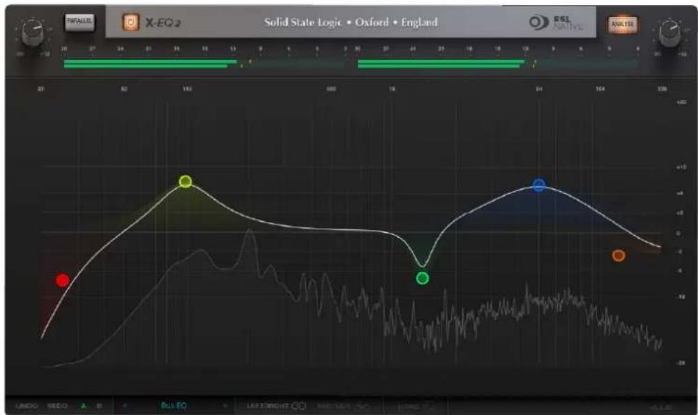
X-EQ 2 is a versatile and highly configurable EQ plug-in that allows you to create up to 24-bands per instance. X-EQ 2 now features SSL's proprietary 'anti-cramping' algorithms for an unparalleled open and transparent sound. X-EQ 2 is the ultimate EQ toolkit, with 17 different EQ types and filter shapes, giving you the best of analogue in an unrestricted and versatile digital environment. Each band is switchable between bell, shelf, low pass or high pass filter types, so you can create the EQ you need for the task at hand. X-EQ 2 also features brand new spatial processing options, band soloing, as well as the classic X-EQ 'Parallel' mode for recreating the cherished sound of parallel passive EQ circuits.
line
| Time | Value | |------|-------| | 0 | -5.0 | | 182 | 10.0 | | 24 | -5.0 | | 364 | 10.0 |Key Features
- 24-band fully parametric high quality digital EQ, featuring unique anti-cramping algorithms with no additional CPU processing cost.
- A total of 17 different filter types: 5 different cut filters, 9 bell shapes, shelving filters, a parallel mode, and custom HPF/LPF modes.
- Extensive control options including draggable EQ graph nodes, mouse wheel adjustment and numerical data entry.
- Extremely low noise and low non-linear distortion filter algorithms resulting in the residual THD+N significantly lower than 24-bit quantisation noise.
- Proprietary preset management functions providing compatibility between all major DAW platforms.
- A/B functionality for easy comparison of any two settings.
• Mid/Side and Left/Right spatial processing options.
• Individual band solo and bypass.
• Real-time FFT Analyser showing the result of the EQ processing on the audio spectrum. - Phase & Step response graphs to show the effect of EQ processing.
- Superb mastering-grade audio quality delivered by 64-bit floating point engine.
- Preset library based on settings used by some of the world's top mix engineers.
Vocalstrip
Vocalstrip is a collection of refined tools for superior vocal processing. It features four configurable processing blocks: an SSL Compander, De-esser and De-ploser, and an application specific EQ. Simply add FX and your vocal tracks are good to go!

text_image
Vocalstrip 2 Solid State Logic • Oxford • England SSL NATIVE OUTPUT INPUT AS OUTPUT OUTPUT LOUD EVENTS 0 12 15 24 MODE | SPLIT BROADCAST MODE | SPLIT BROADCAST COMPANDER DE-ESSER DE-PLOSER EQUALISER ATTACK RATIO THRESHOLD THRESHOLD FREQUENCY THRESHOLD FREQUENCY SOFT KNEE DRIVE LOOK AHEAD LISTEN LOOK AHEAD LISTEN RELEASE MAKEUP GAIN LEDDO REDO A B Default Preset DE-ESSER DE-PLOSER EQUALISER COMPANDERKey Features
- Intelligent De-esser.
- Intelligent De-ploser.
- Three-band EQ.
- Compander featuring compression, downwards expansion and output drive.
- Extensive visual feedback including a real-time FFT analyser showing the result of the EQ processing on the audio spectrum.
- Complete control over process order.
- Extensive control options including mouse wheel adjustment and numerical data entry.
- Proprietary preset management functions providing compatibility between all DAW platforms.
- A/B functionality for easy comparison of any two settings.
• Global latency-free bypass. - Superb mastering-grade audio quality delivered by a 64-bit floating point engine.
- Preset library based on settings used by some of the world's top mixing engineers.
Drumstrip
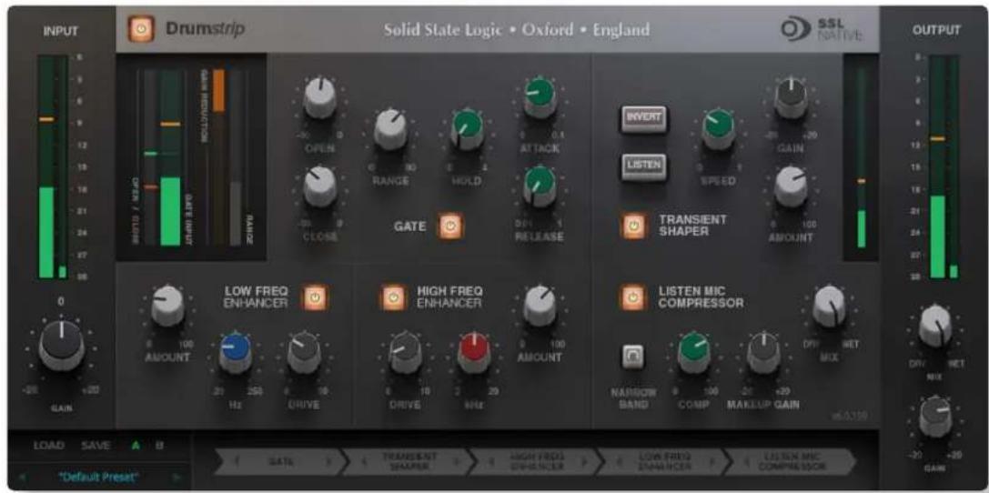
The Drumstrip plug-in brings a unique blend of tools to the SSL Native platform, which provides an unprecedented amount of control over the transient and spectral elements of drum and percussion tracks. Manipulation that previously may have been time-consuming or impossible with traditional EQ and dynamics processing becomes elegant and rewarding with the SSL Drumstrip.
text_image
INPUT Drumstrip Solid State Logic • Oxford • England SSL NATIVE OUTPUT 0 12 19 24 27 30 OPEN / LIME OPEN / LIME LIME / LIME GATE CLOSE RANGE HOLD ATTACK GATE PRELEASE INTERT INTERNATIONAL LISTEN SPEED GAIN TRANSIENT SHAPER AMOUNT LOW FREQ ENHANCER HIGH FREQ ENHANCER LISTEN MIC COMPRESSOR NASHION BAND COMP MAKEUP GAIN Diff. NET MIX DIV. NET V6.0.150 LOAD SAVE A B SATS TRANSIENT TEMPER HIGH FREQ ENHANCER LOW FREQ ENHANCER LISTEN MIC COMPRESSOR "Default Preset"Key Features
- Transient shaper capable of drastically changing the attack characteristics of rhythmic tracks. An audition mode makes for easy setup.
- Highly controllable gate featuring both open and close thresholds, attack, hold, release and range control.
- SSL Listen Mic Compressor with extra functionality.
- Separate high and low frequency enhancers provide spectral control not achievable with traditional EQ.
- Peak and RMS metering on both input and output.
- Wet/dry controls on both the main output and the LMC allow parallel processing to be easily dialled in.
- Process order control over all five sections gives complete flexibility over the serial signal chain.
• Latency-free bypass of all processing.
X-ValveComp
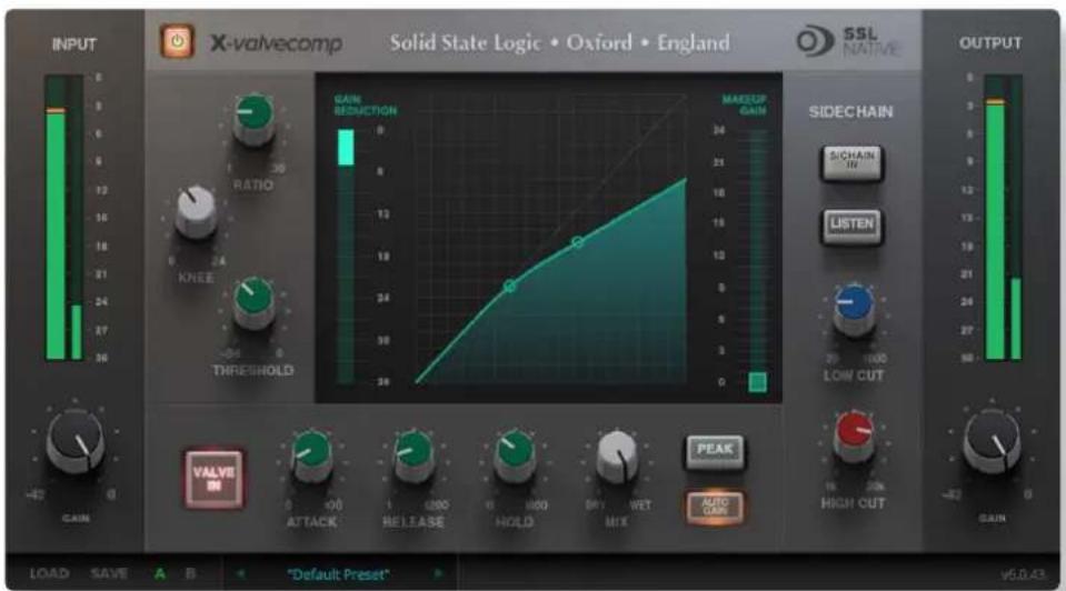
X-ValveComp is a fully-featured channel compressor with valve emulation, side-chain with filters and a wet/dry "Mix" control for parallel processing.
text_image
INPUT X-valvecomp Solid State Logic • Oxford • England SSL NATIVE OUTPUT GAIN REDUCTION RATIO KNEE THRESHOLD MAKEUP GAIN SIDECHAIN S/CHAIN IN LISTEN 20 1000 LOW CUT VALVE IN ATTACK RELEASE HOLD BUT WET MIX PEAK AUTO CHAP HIGH CUT GAIN LOAD SAVE A B "Default Preset" v6.0.43Key Features:
- Mode: Switches between Peak & RMS response.
- Input side-chain filtering.
- Valve In switch; introduces a tube compressor emulation for saturating the signal by adding harmonics.
- Auto make-up gain.
• Threshold, ratio, adjustable knee. - Mix control for parallel compression.
X-Saturator
X-Saturator allows the user to introduce harmonic distortion to a signal to add some pleasing “analogue character”. The X-Saturator emulates analogue gain circuits that introduce harmonic distortion when driven and can act as a veritable time machine of processing sounds, covering everything from smooth tube harmonics to screaming crushed techno sounds.

text_image
INPUT X-saturator SSL NATIVE OUTPUT -30 -48 -24 -10 -6 -3 dB Solid State Logic • Oxford • England +8dB GAIN DEPTH 100% 2nd 3rd HARMONICS DRIVE +6 +12 +18 DRF MIX NET 50% 54% SHAPE -30 0 LOAD SAVE A B "Default Preset" Solid State Logic • Oxford • England √6.0.124Key Features:
- Emulates analogue gain circuits.
• The Drive controls the input level of the plug-in. - By adjusting the Harmonics control the distortion characteristics can be shifted from 50's valve-style overdrive (if the Harmonics selection control is turned fully anti-clockwise for 2nd harmonic distortion) to 70's transistor-style grit (if the Harmonics selection control is turned fully clockwise for 3rd harmonic distortion).
- Depth and Shape control the amount of harmonics injected back into the signal, enriching the sound.
- Boost adds 6dB of headroom to avoid internal clipping.
• Dry/Wet allows parallel processing.
X-Phase
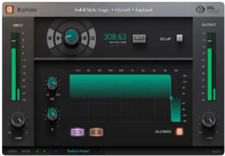
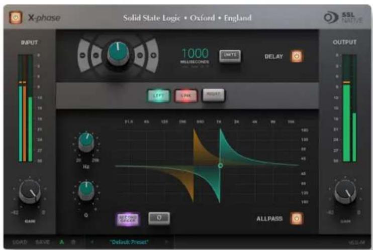
X-Phase is an all-pass filter and time alignment tool for manually adjusting the phase. It can be used to time/phase align signals, for example from a stereo set of overhead mics on a drum kit.
text_image
X-phase Solid State Logic • Oxford • England INPUT 308.63 MIL SECONDS UNITS DELAY OUTPUT Hz ALLPASS LOAD SAVE A "Default Preset" v5.0.0Mono Version
text_image
X-phase Solid State Logic • Oxford • England INPUT 1000 MULSECONDS UNITS DELAY OUTPUT ALLPASS GAIN 11.8 45 125 340 640 940 124 24 36 48 60 92 124 Hz ALLPASS LOAD SAVE A "Default Preset" MELAMStereo Version
Key Features
- X-Phase is an all-pass filter and time alignment tool for manually adjusting the phase.
- The gain is linear across the frequency range, but a change in phase is applied such that it 'wraps' at a specific frequency and converges to or for all other frequencies.
- The Q-Factor of the filter will adjust the rate of phase-change across the frequency spectrum.
• 2nd Order inverts the filter. - Delay (in various units).
- Link L/R for stereo signals.
• 180 degrees phase shift with All-pass 'phase' button.
FlexVerb
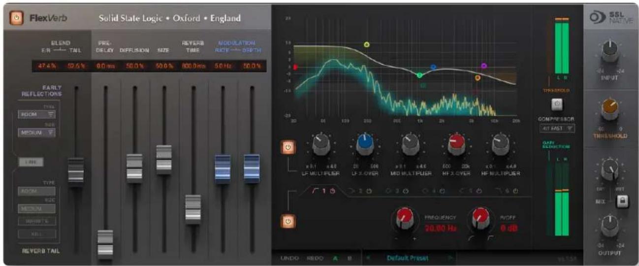
FlexVerb is a fully-featured SSL reverb plug-in designed to get a professional mix-ready sound in a quick and intuitive way. Its split early-late reflection architecture allows you to flexibly add the body and tone of different early room reflections, complimented by the richness of a variety of expansive reverb tail options. Complete with 6-band EQ and input side-chain compressor, FlexVerb is easy to use and an extremely powerful creative tool for the audio professional.
text_image
FlexVerb Solid State Logic • Oxford • England BLEND E.R. —— TAIL 47.4% 52.6% PRE- DELAY DIFFUSION SIZE 50.0% 50.0% REVERB TIME 800.0 ms 50 Hz 50.0% MODULATION RATE —— 8GHz EARLY REFLECTIONS TYPE ROOM SIZE MEDIUM LINE TYPE ROOM RDC MEDIUM INPUT S KELI REVERB TAIL 10 20 30 40 50 60 70 80 90 100 110 120 130 140 150 160 170 180 190 200 210 220 230 240 250 260 270 280 290 300 310 320 330 340 350 360 370 380 390 400 410 420 430 440 450 460 470 480 490 500 510 520 530 540 550 560 570 580 590 600 610 620 630 640 650 660 670 680 690 700 710 720 730 740 750 760 770 780 790 800 810 820 830 840 850 860 870 880 890 900 910 920 930 940 950 960 970 980 990 1000 1100 1200 1300 1400 1500 1600 1700 1800 1900 2000Key Features:
- Four Reverb Types: Room, Hall, Plate, and Chamber.
- Early & Late Reflection types can be independently selected; for example, Small Room Early Reflections, with a Large Plate Reverb Tail.
- 6 Band SSL EQ, with 3 bands of reverb time multipliers.
- Output compressor (applied to reverb only) side-chained by the 'dry' input signal; useful to help sit in the mix.
- Lockable Dry/Wet Mix control; fix the mix of dry and wet signal when switching between presets.
• Infinity reverb time switch. - Reverb tail kill switch.
• Graphical display of EQ and reverb time multipliers, including FFT analysis with after-glow.
1. Software Setup
SYSTEM REQUIREMENTS
Before starting the installation process, confirm that your system meets the minimum system requirements to run SSL Native plug-ins.
Windows
- Windows 7, (64 bit) 8 (64 bit), 8.1 (64 bit), and Windows 10 (64 bit).
- Intel Core 2 (or comparable) CPU running at 2.4GHz or higher.
- 4GB of RAM minimum, 8GB preferable.
- VST 2(64 bit), VST3 (64 bit), AAX Native (64 bit).
Mac
- OS X 10.10 Yosemite or higher (32 or 64-bit).
- Intel Dual Core Mac running at 2.4GHz or higher.
- 4GB of RAM minimum, 8GB preferable.
- AU (32 or 64bit), VST2 (32 or 64-bit), VST3 (32 or 64-bit), AAX Native (32 or 64-bit).
BUYING PLUG-INS
SSL Native plug-ins are licensed using an iLok 2 or iLok 3 USB device, or machine-based iLok licensing. In order to purchase SSL Native iLok licenses, go to the SSL Webstore and login to your SSL account. If you don't have an SSL account, you can create one by following the steps below:
CREATING AN SSL ACCOUNT
Click on this icon: 📷 then click on Create New Account and fill in your details.
You will be sent a password by email. Once you have received this email, you are ready to continue.
Create new account | Log in | Reset your password
User account
ACCOUNT INFORMATION
Username: *
Spaces are allowed; punctuation is not allowed except for periods, hyphens, and underscores.
E-mail address: *
A valid e-mail address. All e-mails from the system will be sent to this address. The e-mail address is not made public and will only be used if you wish to receive a new password or wish to receive certain news or notifications by e-mail.
LOGGING INTO THE SSL WEBSITE
Click on LOG IN, type your username you created and the password sent to you by email and click on the Log In button below the password.
Create new account | Log in | Reset your password
User account
Username: *
Enter your MySQL username.
Password: *
Enter the password that accompanies your username.
Log in
SSL WEBSTORE
From the SSL Webstore (found here: http://store.solidstatelogic.com/) navigate to the SSL Native Plug-ins webstore page and click "Add to Cart" for each of the plug-in licenses you wish to purchase. Complete the check-out and purchase processes.
SSL Native Plug-ins Product Catalogue
• All prices exclude VAT or Sales Tax.
All SSL Native plug-ins are available for a 'free fully functional demo' - click here to find out more
Before you can use these products you must download and install the SSL Native software. It can be downloaded here.
* All SSL Native plug-ins are available for immediate online purchase. Buying the plug-in(s) will prompt you to enter your iLok account username. The license(s) will appear in this iLok account. You will need to download the latest iLok License Manager from www.iLok.com, login to your account, then activate the license(s) onto an iLok 2 or 3 USB device.
- All physical goods will be dispatched within three days of purchase unless otherwise stated. Shipping for the SSL Native Dongle is free.
- Goods are shipped from the UK with all Tariffs and Import Duties remaining the responsibility of the customer.
• You can read the SSL Native Terms & Conditions here
SSL Native Drumstrip
text_image
Front panel of a vintage electronic device with labeled buttons and ports, including 'SETON', 'ACTON', and 'SIGNAL'.Add to cart
Drumstrip takes drum sounds from ordinary and average to vibrant and exhilarating in a few quick, easy steps. Read More about
Price: €179.00
SSL Native Essentials Bundle

natural_image
Two black audio equipment monitors displaying various signal channels and a digital display (no visible text or labels)Add to cart
The classic SSL console sound for your DAW. This bundle includes the SSL Native EQ & Dynamics Channel (Read More) and the SSL Native Bus Compressor (Read More) plug-ins.
Price: €407.00
During the purchase process you will be asked to enter your iLok User ID, then validate it (if it is not already present in your SSL account). If you do not have an iLok account, you can create one here: https://www.ilok.com/#!registration
ACTIVATING PLUG-IN LICENSES
Once you have successfully completed the purchasing process, your licenses will have been deposited in your chosen iLok account and require authorisation onto either your machine, or a physical iLok 2 / 3.
- Open iLok License Manager.
- Log in to your iLok account.
- *If required, connect your iLok 2 or 3 device to the computer. If an unregistered iLok is connected, a pop-up will appear asking if you would like to add the iLok to your account; select "yes". The iLok will be registered to your account.
- Activate your SSL License(s) by right-clicking the license you wish to activate and select "Activate", select a location, and then click the "Activate" button.
| SSL Native | Show Details | Solid State Logic | Product | |
| SSL Native | Hide Details | Solid State Logic | Product | |
| SSL Native | Activate | Solid State Logic | Product | |
| SSL Native | Deactivate | Solid State Logic | Product | |
| SSL Native | Take OwnershipTransfer License... | Solid State Logic | Product | |
| SSL Native X-Saturator | Solid State Logic | Product | ||
| SSL Native Drumstrip | Solid State Logic | Product | ||
| SSL Native Vocalstrip | Solid State Logic | Product |
For further information on using iLok License Manager, please see the iLok website here: www.ilok.com/
DOWNLOADING THE SOFTWARE
Please download the latest SSL Native software from the SSL Native Downloads page. Note that you do not need to purchase plug-ins in order to download them, although you will need to register on the SSL website and activate the licenses before use.
SSL Native plug-ins
SSL console grade processing for your DAW.
Overview | Free Demo | Free Cross Grade | iLok2 Copy Protection | Specifications | Gallery | Documents | Downloads | Tutorials | FAQ | Videos |
Downloads
Please note that these installers contain all 10 SSL Native plug-ins. If you have only purchase a single plug-in and do not wish to demo any of the others, be sure to deselect them when prompted in the installation process.
SSL Native Intel Mac (64-Bit)

SSL Native Intel Mac (32-Bit)

SSL Native PC (64-Bit)

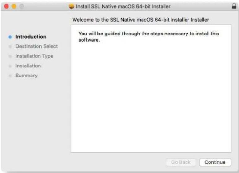
INSTALLING THE SOFTWARE (MAC)
- Double click the SSL Native disk image file that you downloaded to mount the disk image.
- Run the SSL Native Plug-ins installer and follow the on-screen instructions.
text_image
Install SSL Native macOS 64-bit Installer Welcome to the SSL Native macOS 64-bit installer Installer Introduction Destination Select Installation Type Installation Summary You will be guided through the steps necessary to install this software. Go Back ContinueDuring the installation process you can choose which plug-ins and formats you don't require by unticking the appropriate boxes:

text_image
Install SSL Native macOS 64-bit Installer Custom Install on "Macintosh HD" Package Name Action Size ✓ SSL Native Bus Compressor 57.2 MB ✓ AAX Upgrade 14.7 MB ✓ Audio Units Upgrade 14.2 MB ✓ VST Upgrade 14 MB ✓ VST3 Upgrade 14.3 MB ✓ SSL Native Channelstrip 76.2 MB ✓ AAX Upgrade 19.5 MB ✓ Audio Units Upgrade 19 MB ✓ VST Upgrade 18.8 MB ✓ VST3 Upgrade 19 MB ✓ SSL Native Drumstrip 69.9 MB Space Required: 504.2 MB Remaining: 91.68 GB Go Back ContinueIn the disk image you will also find a file named iLok License Support.dmg. If you do not already have the iLok software installed – for example if this is the first time you have used your iLok – you should double click this disk image and run the installer. If you have a newer version of the software already installed you will be notified and prompted to quit the installer.
If this is the first time you are installing the SSL Native V6 plug-ins you will need to activate the licenses in your iLok account to your machine or a physical iLok 2/3 device. Please see the 'Activating Plug-In Licenses' section of this user guide for more information.
Please note that a newer version of iLok License Manager may be available here: https://www.ilok.com/
INSTALLING THE SOFTWARE (WINDOWS)
- Double click the SSL Native zip file that you downloaded to open it.
- Run the SSL Native Setup.exe file and follow the on-screen instructions:

text_image
Welcome to the SSL Native 64-bit v6.0.49 Setup Wizard This wizard will guide you through the installation of SSL Native 64-bit v6.0.49. It is recommended that you close all other applications before starting Setup. This will make it possible to update relevant system files without having to reboot your computer. Click Next to continue.During the installation you can choose which plug-ins and formats you don't require by unticking the appropriate boxes:

text_image
SSL Native 64-bit v6.0.49 Setup Solid State Logic USFORD - ENGLAND Choose Components Choose which features of SSL Native 64-bit v6.0.49 you want to install. Check the components you want to install and uncheck the components you don't want to install. Click Next to continue. Select components to install: SSL Native Plug-ins SSL Native Bus Compressor SSL Native Channel Strip SSL Native Drumstrip SSL Native Vocalstrip SSL Native X-Comp SSL Native X-EQ SSL Native X-Phase SSL Native X-Saturator Space required: 1.0GB Solid State Logic - SSL Native 64-bit v6.0.49 Beta < Back Next > CancelIn the zip file you will also find a file named License Support.exe. If you do not already have the iLok software installed - for example if this is the first time you have used your iLok, you should double click this file to run the installer. If you have a newer version of the software already installed you will be notified and prompted to quit the installer.
If this is the first time you are installing the SSL Native V6 plug-ins you will need to activate the licenses in your iLok account to your machine or a physical iLok 2/3 device. Please see the 'Activating Plug-In Licenses' section of this user guide for more information.
Please note that a newer version of iLok License Manager may be available here: https://www.ilok.com/
LOGIC ESSENTIALS - MAC ONLY
Inside the .dmg installer is a folder called Logic Essentials, containing the SSL Native Logic Pro Essentials Installer.pkg.

text_image
SSL Native macOS v6.5 Installer Logic Essentials SSL Native macOS v6.5 installer.pkg SSL Native Uninstaller.app SSL Native macOS v6.5 InstallerThe SSL Native Logic Pro Essentials Installer.pkg is for Logic Pro users; it installs custom MCU maps for using an MCU control surface with the SSL Native plug-ins in Logic Pro, as well as Logic Pro short names. These can be edited from the Plug-in Manager in Logic if you wish: Logic Pro > Preferences > Plug-in Manager...
| SSL Native...ompressor v6 | SSL Bu...ressor | Bus Comp | effect | SSL |
| SSL Native Channelstrip v6 | SSL Ch...elstrip | Channelstrip | effect | SSL |
| SSL Native Drumstrip v6 | SSL Drumstrip | Drumstrip | effect | SSL |
| SSL Native FlexVerb | SSL FlexVerb | FlexVerb | effect | SSL |
| SSL Native Vocalstrip v6 | SSL Vocalstrip | Vocalstrip | effect | SSL |
UNINSTALLING THE SOFTWARE (MAC)
As of SSL Native v6.5, the mountable .dmg contains an uninstaller. Running this uninstaller will remove all SSL Native plug-ins from your system. It will not uninstall any SSL Native presets.
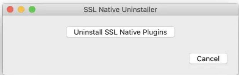
text_image
SSL Native Uninstaller Uninstall SSL Native Plugins Cancel2. Channel Strip
INTRODUCTION
The Channel Strip plug-in provides a complete SSL channel strip, based on the processing blocks of SSL's analogue consoles, and includes high and low pass filters, a four band equaliser, compressor/limiter and gate/expander. The channel strip can run in mono or stereo.
Before examining the plug-in in detail, the diagram below provides an operational overview.

flowchart
graph TD
    A["Above the main plug-in window is a set of controls that are specific to your host application. Please refer to your host application's user guide for guidelines on using these controls."] --> B["Filters"]
    B --> C["Turn filter knobs up to engage."]
    C --> D["EQ"]
    D --> E["BELL switches low and high EQ bands from shelf to parametric mode."]
    E --> F["E switches EQ characteristics between SSL E and G Series consoles."]
    F --> G["EQUALISATION"]
    G --> H["Activates EQ"]
    H --> I["Turn up input gain to a suitable level."]
    I --> J["PEAK switches signal detection between Peak and RMS modes."]
    J --> K["Engages Dynamics"]
    K --> L["Compression and Expansion meters."]
    L --> M["To activate Gate/Expander turn up RANGE."]
    M --> N["When adjustments are complete, correct the output gain to a suitable level."]
    N --> O["Dynamics"]
    O --> P["EXPAND switches between Gate and Expander."]
    P --> Q["S/CHAIN LISTEN routes Dynamics side-chain to channel output."]
    Q --> R["S/CHAIN LISTEN routes Dynamics side-chain to channel output."]
    R --> S["EXPAND switches between Gate and Expander."]
    S --> T["DYNAMICS GATE / EXPANDER"]
    T --> U["DUALD THRESHOLD"]
    U --> V["FRADE RELIEASE COMPRESSOR"]
    V --> W["FAST ATTACK switches the compressor to a fast attack time."]
    W --> X["To activate Compressor turn up RATIO."]
    X --> Y["Changes Signal Processing Order"]
    Y --> Z["Switch between main and alternative plug-in settings."]
    Z --> AA["LOAD SAVE A B "Default Press""]
    AA --> AB["Internal plug-in bypass for smoother A/B comparisons."]
The following techniques and automation information for controlling the Channel Strip Plug-in are common to all of the SSL Native plug-ins.
- To press a switch in a plug-in, simply click on it. With all plug-ins, an on-screen indication adjacent to or surrounding the switch will indicate when the switch is active.
- To turn a knob, click on it and drag it up and to the right. If your mouse has a scroll wheel, you can also turn knobs by hovering over them and turning the scroll wheel.
- To move a knob slowly for fine adjustments, hold the To reset a knob to its default value, click on the knob following on your keyboard whilst turning/scrolling: whilst holding the following on your keyboard:
| Fine Adjust for Host Type | Mac Windows | |
| AU | ⌘ ('Command') | - |
| VST | ⌘ ('Command') | Ctrl |
| VST3 | ⌘ ('Command') | Ctrl |
| AAX | ⌘ ('Command') | Ctrl |
| Reset for Host Type | Mac Windows |
| AU | Alt - |
| VST | Alt Alt |
| VST_3 | Alt Alt |
| AAX | Alt Alt |
- To view the value for any knob, hover over the knob cap with the mouse.
Automation
Every plug-in parameter can be automated in host applications that support automation. The method for recording and editing automation varies from host to host. For specific instructions on using automation within the host, consult the host application's documentation.
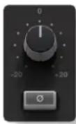
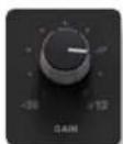
INPUT SECTION
Turn the GAIN knob to control the level of the incoming audio signal. The post-gain signal level is shown above. Press to invert the phase of the input signal.
text_image
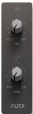
HP OUT 500 Hz LP OUT 3.0 kHz FILTERFILTER SECTION
There are two filters in the Filter section:
- The upper knob controls an 18dB/Octave high pass filter (20Hz to 500Hz).
- The lower knob controls a 12dB/Octave low pass filter (3kHz to 22kHz).
Filters are inactive when turned fully anti-clockwise (OUT). Turn them clockwise to move the filter frequency in from its extremity.
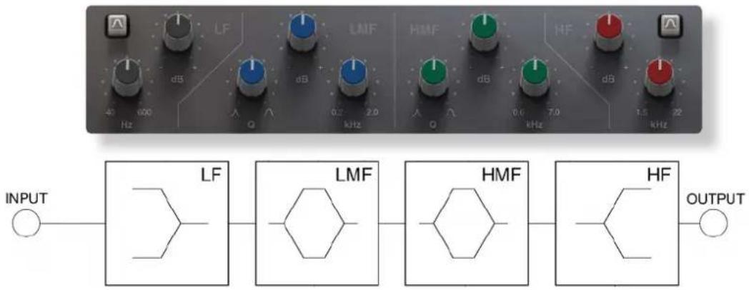
EQUALISER SECTION
To use the EQ, switch it into circuit by pressing the EQ IN switch.
The EQ section has four bands, each with its own knob colour. All bands have gain and frequency control. The low (LF) and high (HF) bands are shelved by default (as shown below) but can be switched to a bell shape (parametric) by pressing the BELL button. The low-mid (LMF) and high-mid (HMF) bands also have Q control:
text_image
LF LMF HMF HF 40 600 Hz dB Q dB 0.2 2.0 kHz 0.0 7.0 kHz 1.5 22 kHz INPUT LF LMF HMF HF OUTPUT| Band LF LMF HMF HF | |||
| Frequency range | 40Hz - 600Hz 200Hz - 2kHz 600Hz - 7kHz 1.5kHz - 22kHz | ||
| Gain range ±16.5dB ±20dB ±20dB ±20dB | |||
| Q range - 0.5 - 2.5 0.5 - 2.5 | - | ||
Press the E to switch the EQ emulation from G Series to E Series consoles. The diagrams below display the difference between them:
G Series: The bell curve has a more rounded shape at low gains. G Series EQ is more subtle and is generally more suited to instruments and vocals.
E Series: The bell curve is slightly more pointed. E Series EQ is more aggressive and is therefore better for removing problem frequencies. It is generally more suited to drums.
At full boost or cut, both curves are identical.

line
| x | 'E type' | 'G type' | Both | |-------|----------|----------|------| | 10 | 0.0 | 0.0 | 0.0 | | 1k | 5.0 | 3.0 | 4.0 | | 10k | 20.0 | 15.0 | 22.0 | | 20k | 0.0 | 0.0 | 0.0 |DYNAMICS SECTION
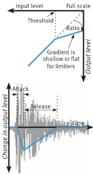
The Dynamics section includes a Compressor/Limiter and an Expander/Gate. Both sections work independently but can be operational at the same time, providing sophisticated control of signal levels. The diagrams down the right-hand side of the page give a simplified overview what each control represents.
Press DYN IN to switch the Dynamics into circuit.
Compressor/Limiter
To activate the Compressor/Limiter, turn the RATIO knob so that it is no longer set to 1:1.
To turn the compressor into a :1 limiter, turn the knob fully clockwise.

text_image
COMPRESSOR PEAK FAST ATTACK 1 00 +10 -20 0.1 -6 RATIO THRESHOLD RELEASEThere is no gain makeup control as the THRESHOLD knob controls both the level at which gain reduction is introduced and the gain make-up, keeping the output level reasonably steady regardless of the compression.
RELEASE controls how quickly the level returns to normal after the input level has dropped below the threshold (measured in seconds). The attack time is adjusted automatically to match the audio. To choose a constantly fast attack time, press the FAST ATTACK switch.
Press the PEAK button to switch from RMS to peak signal detection. In normal RMS mode the compressor reacts to the average signal level and has a soft knee characteristic. When switched to peak mode, it responds to peak signal level and introduces a hard knee characteristic, resulting in more dramatic compression.
The level of compression being introduced is shown in the left-hand of the two meters in the centre of the Dynamics section.
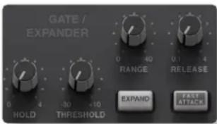
Expander/Gate
To activate the Expander/Gate, turn the RANGE knob so that it is no longer zero.
text_image
GATE / EXPANDER 0 40 0.1 4 RANGE RELEASE HOLD THRESHOLD EXPAND: FAST ATTACKThe green indicators in the right-hand of the two meters in the centre of the Dynamics section show the amount of gain reduction being introduced.
By default, the Expander/Gate section functions as a gate. To switch to the expander, press the EXPAND switch.
The THRESHOLD function uses different levels to ‘open’ the gate to audio and to ‘close’ it again – the level at which the expander opens is higher than the level at which it closes again. In other words, when the expander is opened, it stays open until the signal level crosses the quieter ‘close’ threshold. This is known as hysteresis and is very useful as it allows instruments to decay more naturally. The word ‘Threshold’ normally refers to the ‘open’ threshold.
HOLD controls the delay before the signal level starts reducing again, and RELEASE controls how quickly the level then reduces. Note that the RELEASE interacts with the RANGE, which determines the depth of gain reduction.
The attack time (the time taken for the Expander/Gate to 'recover' once the signal level is above the 'deactivate' threshold) is normally set to 1.5ms per 40dB. Press the FAST ATTACK switch to introduce a faster attack time of 100 s per 40dB. This is useful when gating signals with a steep rising edge, such as drums.
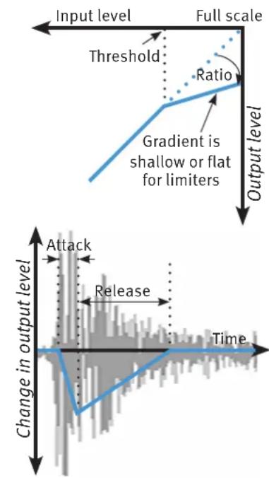
text_image
Input level Full scale Threshold Ratio Gradient is shallow or flat for limiters Output level Change in output level Attack Release Time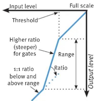
text_image
Input level Full scale Threshold Higher ratio (steeper) for gates Range Ratio 1:1 ratio below and above range Output level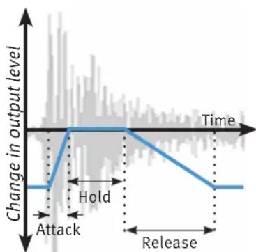
text_image
Change in output level Time Hold Attack ReleaseDynamics Values
The value ranges associated with the dynamics controls are as follows:
| Ratio Threshold / Range Release time Attack time | ||||
| Compressor 1:1 to ∞:1 | -20dB to +10dB 0.1s to 4s | 3ms to 30ms (automatic)3ms in Fast Attack | ||
| Expander | Gate: 40:1Expander: 2:1 | 30dB to +10dBRange: 0dB to 40dB | Hold os to 4sRelease 0.1s to 4s | 1.5ms /40dB100μs /40dB in Fast Attack |
Side-chain Processing Order
The EQ and filter sections can be assigned to the Dynamics side-chains, allowing for advanced processes like de-essing. This is done using the DYNAMICS Side-chain EQ and FILTER switches at the bottom of the plug-in window.

text_image
EQ DYNAMICS SIDECHAIN FILTERThe Process Order display at the base of the plug-in window indicates the side-chain assignments. Both EQ and filter sections can be assigned to the side-chain together, in which case the EQ precedes the filter.
To listen to the signal feeding the side-chain, press the S/C LISTEN button in the Output section to route the side-chain signal to the channel output.
Remember to cancel the S/C LISTEN button once you have finished auditioning the side-chain!
CHANNEL PROCESSING ORDER
Signal processing order is shown in the graphic at the bottom of the plug-in window.

The default plug-in order is Filters ▶ EQ ▶ Dynamics.
To change the channel processing order, click on left or right arrows for that section to move it earlier or later in the plug-in signal path.
Please note: EQ > DYNAMICS > FILTER is not possible. This is because on SSL's analogue consoles, if the 'filter to input' switch is not activated, the filter will always occur directly after the EQ section.
OUTPUT SECTION

The Output section allows you to ensure that the signal retains a good level after all the signal processing. The signal level is shown above the knob.
S/CHAIN LISTEN routes the side-chain directly to the output, so you can monitor the side-chain signal.
Input and Output Metering
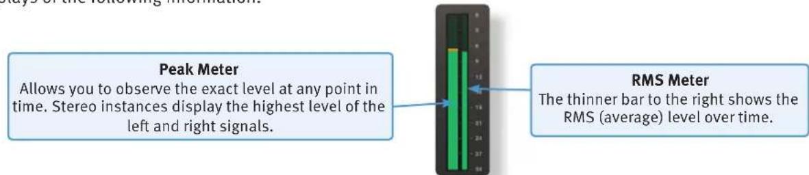
The input and output sections at either side of the plug-in window provide input and output gain control, along with displays of the following information:
Peak Meter
Allows you to observe the exact level at any point in time. Stereo instances display the highest level of the left and right signals.

RMS Meter
The thinner bar to the right shows the RMS (average) level over time.
When clipping occurs, the meter will turn red. It will remain red until the meter is reset by clicking on the meter.
Presets
Factory presets are included in the plug-in installation, installed in the following locations:
Mac:
Library/Application Support/Solid State Logic/SSLNative/Presets/Channelstrip
Windows 64-bit:
C:\ProgramData\Solid State Logic\SSL Native\Presets\Channelstrip

Switching between presets can be achieved by clicking the left/right arrows in the preset management section of the plug-in GUI, and by clicking on the preset name which will open the preset management display.
Preset Management Display
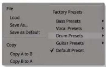
text_image
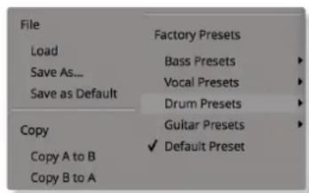
File Load Save As... Save as Default Copy Copy A to B Copy B to A Factory Presets Bass Presets Vocal Presets Drum Presets Guitar Presets Default PresetThere are a number of options in the Preset Management Display:
- Load allows loading of presets not stored in the locations described above.
- Save As... allows for storage of user presets.
- Save as Default assigns the current plug-in settings to the Default Preset.
- Copy A to B and Copy B to A assigns the plug-in settings of one comparison setting to the other.
A-B Comparisons

The A B buttons at the base of the screen allows you to load two independent settings and compare them quickly. When the plug-in is opened, setting A is selected by default. Clicking the A or B button will switch between setting A and setting B.
UNDO and REDO functions allow undo and redo of changes made to the plug-in parameters.
3. Bus Compressor
INTRODUCTION
The Bus Compressor plug-in is based on the legendary centre section stereo bus compressor found on SSL's large format analogue consoles. It provides high quality stereo compression for critical control over the dynamic range of audio signals.
The compressor can be run in mono or stereo modes and can be used for practically any application that requires superior compression. For example, place it over a stereo mix to 'glue' the mix together whilst still maintaining a big sound, or use it on drum overheads or whole drum kits for very effective control of drum dynamics.
The interface techniques for the Stereo Bus Compressor are identical to those for the Channel Strip.
Automation
Automation support for the Stereo Bus Compressor is the same as for the Channel Strip.
Control Parameters
Below is a description of the Stereo Bus Compressor's parameters.
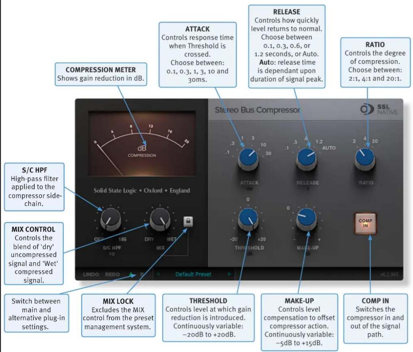
text_image
COMPRESSION METER Shows gain reduction in dB. ATTACK Controls response time when Threshold is crossed. Choose between: 0.1, 0.3, 1, 3, 10 and 30ms. RELEASE Controls how quickly level returns to normal. Choose between 0.1, 0.3, 0.6, or 1.2 seconds, or Auto. Auto: release time is dependant upon duration of signal peak. RATIO Controls the degree of compression. Choose between: 2:1, 4:1 and 20:1. S/C HPF High-pass filter applied to the compressor side- chain. MIX CONTROL Controls the blend of 'dry' uncompressed signal and 'Wet' compressed signal. Switch between main and alternative plug-in settings. MIX LOCK Excludes the MIX control from the preset management system. THRESHOLD Controls level at which gain reduction is introduced. Continuously variable: -20dB to +20dB. MAKE-UP Controls level compensation to offset compressor action. Continuously variable: -5dB to +15dB. COMP IN Switches the compressor in and out of the signal path.Presets
Factory presets are included in the plug-in installation, installed in the following locations:
Mac:
ibrany/Application Support/Solid State Logic/SSLNative/Presets/BusCompressor
Windows 64-bit:
C:\ProgramData\Solid State Logic\SSL Native\Presets\BusCompressor

Switching between presets can be achieved by clicking the left/right arrows in the preset management section of the plug-in GUI, and by clicking on the preset name which will open the preset management display.
Preset Management Display
text_image
File Load Save As... Save as Default Copy Copy A to B Copy B to A Factory Presets Bass Presets Vocal Presets Drum Presets Guitar Presets Default PresetThere are a number of options in the Preset Management Display:
- Load allows loading of presets not stored in the locations described above.
- Save As... allows for storage of user presets.
- Save as Default assigns the current plug-in settings to the Default Preset.
- Copy A to B and Copy B to A assigns the plug-in settings of one comparison setting to the other.
A-B Comparisons

The A B buttons at the base of the screen allows you to load two independent settings and compare them quickly. When the plug-in is opened, setting A is selected by default. Clicking the A or B button will switch between setting A and setting B.
UNDO and REDO functions allow undo and redo of changes made to the plug-in parameters.
4. X-Comp
INTRODUCTION
The illustration below gives an overview of some of the X-Comp features which are described in full over the following pages.

text_image
Above the main plug-in window is a set of controls that are specific to your host application. Please refer to your host application's user guide for guidelines on using these controls Internal bypass for smooth in/out comparisons Input level metering and control GR displays gain reduction GR History displays gain reduction over last second Interactive compressor display with draggable nodes I/O Difference display displays the signal's dynamic range. Listen button for auditioning bleed signal Solid State Logic • Oxford • England SSL NATIVE OUTPUT CO DIFFERENCE LIND EVENTS HIGH BLEED ANDOUNT LOW BLEED LISTEN Default Preset Switch between main and alternative plug-in settings Bleed section allows LF and HF bands to bypass the compressor. Display includes draggable nodes. Output level metering and controlThe basic interface techniques for the X-Comp are largely identical to those for the Channel Strip. In addition to these basic techniques, the following are also available:
Threshold and Ratio values can also be controlled directly within the compressor display with draggable nodes. Move the nodes to control the Threshold and the Ratio.
The bleed bands can be adjusted in a similar way.
Automation
Automation support for X-Comp is the same as for the Channel Strip.
CONTROL PARAMETERS
Plug-in Bypass

The power switch provides an internal plug-in bypass. This allows for smoother In/Out comparisons by avoiding the latency issues associated with the host application's Bypass function.
The button must be 'lit' for the plug-in to be in circuit.
Common Compressor Parameters
The diagrams down the right-hand side of the page give a simplified overview of what each control represents, as shown in the compressor display in the centre of the plug-in window.
Knee
The Knee controls how focussed the threshold level is:
- With a hard knee (knob at minimum) the compressor's parameters all come into force at precisely the point at which the threshold is crossed. In the Compression Law diagram, this is shown by a sharp change in gradient at the threshold.
- With a soft knee, the ratio is introduced gradually, starting below the threshold and reaching its full value above the threshold. In the Compression Law graph, this is shown by a curve in the gradient around the threshold.
The Knee control affects both the main threshold point and the Max GR point (see below) in equal measure.
Operational tip. A hard knee allows for greater precision, but can sound more obvious. A soft knee generally provides a more transparent result.
text_image
Input level Full scale Threshold Ratio Gradient is shallow or flat for limiters Output level Change in output level Attack Release TimeMax GR
The Max GR (Maximum Gain Reduction) allows you to set a limit on how much gain reduction can be introduced, replicating the performance of older optical compressors (as shown in the upper diagram above). With a Max GR of 20dB, for example, any signals that would normally be reduced by more than 20dB will only be attenuated by 20dB. By only compressing the middle of the dynamic range you can exert some general dynamic control whilst still preserving the transients for impact.
Bleed
The Bleed controls, located at the bottom of the X-Comp plug-in window, allow you to remove the compressor's effect from high and low frequencies. Frequencies outside the mid-band bypass the compressor and are recombined with the compressed signal at the output. Note that the bypassed signal is not affected by the Make up gain.

flowchart
graph LR
    A["Input"] --> B["Mid-band is compressed in the normal way"]
    B --> C["LF bypass region"]
    B --> D["'Cross-fade' regions defined by bleed %"]
    B --> E["HF bypass region"]
    C --> F["Output"]
    D --> F
    E --> F
    F --> G["Bypass"]
The frequencies and slope of the bleed-band filters are indicated either side of the graph; LF to the left and HF to the right. The slope is measured as a percentage.
The bleed bands can be adjusted by clicking on the values in the displays and dragging up and right in the usual way. Alternatively, they can be adjusted directly using the nodes in the display – brown for low frequencies and blue for high frequencies. Move the nodes horizontally to control frequency and vertically to control percentage
Auditioning Bleed Bands
To listen to the bleed bands on their own, press the Listen button, located below the Make up gain. This mutes the compressed signal, so only the bypass portion of the signal is heard.
COMPRESSOR VALUES
The table below lists the ranges of all of X-Comp's parameters:
| Parameter Min Max | ||
| Input gain -36db +12dB | ||
| Threshold -48dB +12dB | ||
| Ratio 1:1 50:1 | ||
| Knee odB 40dB | ||
| Max GR 20dB 60dB | ||
| Attack time 0.5ms 100ms | ||
| Release time 1ms 2000ms | ||
| Make up gain | -6dB | +36dB |
| LF Bleed | 30Hz | 300Hz |
| HF Bleed | 2kHz | 12kHz |
| Bleed slopes | 0% | 100% |
| Output gain | -36db +12dB |
Input and Output Sections
The input and output sections at either side of the plug-in window provide input and output gain control, along with displays of the following information:
text_image
Peak Meter Allows you to observe the exact level at any point in time. Stereo instances display the highest level of the left and right signals. RMS Meter The thinner bar to the right shows the RMS (average) level over time.When clipping occurs, the meter will turn red. It will remain red until the meter is reset by clicking on the meter.
Turn the GAIN knob in the input section to control the level of the incoming audio signal. The post-gain signal level is shown above.
Turn the GAIN knob in the output section to ensure that the signal retains a good signal level post-processing. The output signal level is shown above the knob.
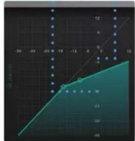
Compression Law Graph
The display in the centre of the plug-in window compares the input and output signals given the current compressor settings. The thicker line indicates the relationship between input and output across the range of levels, while the faint line indicates a 1:1 relationship. In the example to the right, an input level of -21dB results in an output level of -21dB (as this is below the threshold, this indicates a Make-up gain of odB), while an input level of +6dB results in an output level of -7dB.
Threshold and Ratio can be defined by moving the nodes within the display.

line
| X | Y | |---|---| | -30 | -46 | | -25 | -40 | | -20 | -34 | | -15 | -29 | | -12 | -24 | | -8 | -19 | | 0 | -14 | | 8 | -8 | | 12 | -4 | | 18 | 0 | | 24 | 4 | | 30 | 8 | | 36 | 12 | | 42 | 16 | | 48 | 20 | | 54 | 24 | | 60 | 28 | | 66 | 32 | | 72 | 36 | | 78 | 40 | | 84 | 44 | | 90 | 48 | | 96 | 52 | | 102 | 56 | | 108 | 60 | | 114 | 64 | | 120 | 68 | | 126 | 72 | | 132 | 76 | | 138 | 80 | | 144 | 84 | | 150 | 88 | | 156 | 92 | | 162 | 96 | | 168 | 100 | | 174 | 104 | | 180 | 108 | | 186 | 112 | | 192 | 116 | | 198 | 120 | | 204 | 124 | | 210 | 128 | | 216 | 132 | | 222 | 136 | | 228 | 140 | | 234 | 144 | | 240 | 148 | | 246 | 152 | | 252 | 156 | | 258 | 160 | | 264 | 164 | | 270 | 168 | | 276 | 172 | | 282 | 176 | | 288 | 180 | | 294 | 184 | | 300 | 188 | | 306 | 192 | | 312 | 196 | | 318 | 200 | | 324 | 204 | | 330 | 208 | | 336 | 212 | | 342 | 216 | | 348 | 220 | | 354 | 224 | | 360 | 228 | | 366 | 232 | | 372 | 236 | | 378 | 240 | | 384 | 244 | | 390 | 248 | | 396 | 252 | | 402 | 256 | | 408 | 260 | | 414 | 264 | | 420 | 268 | | 426 | 272 | | 432 | 276 | | 438 | 280 | | 444 | 284 | | 450 | 288 | | 456 | 292 | | 462 | 296 | | 468 | 300 | | 474 | 304 | | 480 | 308 | | 486 | 312 | | 492 | 316 | | 498 | 320 | | 504 | 324 | | 510 | 328 | | 516 | 332 | | 522 | 336 | | 528 | 340 | | 534 | 344 | | 540 | 348 | | 546 | 352 | | 552 | 356 | | 558 | 360 | | 564 | 364 | | 570 | 368 | | 576 | 372 | | 582 | 376 | | 588 | 380 | | 594 | 384 | | 600 | 388 | | -30 | -36 | | -25 | -30 | | -20 | -24 | | -15 | -19 | | -10 | -14 | | -5 | -8 | | -10 | -4 | | -5 | -0.5 | | -10 | -4.5 | | -5 | -1.5 | | -5 | -1.5 (estimated) for the last point on the x-axis (X = X + Y). The y-axis values are estimated based on the grid lines representing the x-values. The chart is a line graph of the y-values against the x-values. The title of the chart is 'Figure' in English. The legend is 'Figure' but not explicitly labeled.
Bleed Graph
The bleed graph indicates the frequencies that are bypassing the compressor, as described on the previous page.
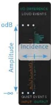
I/O Difference Graph
The I/O Difference meter to the right of the Compression Law graph shows how often each level occurs within the input and output signals. The input is shown on the left and the output on the right.
The vertical scale is amplitude, with odB at the top and - at the bottom. The length of each line protruding from the centre represents the number of incidents of that amplitude over a period of seconds.
In the graphic to the right, the input signal displays a mixture of very loud and very quiet, indicating that the signal has a large dynamic range that is changing very quickly. The output signal indicates that this dynamic range has been made smaller, with the loud bars being reduced in level and the quiet bars being increased.
text_image
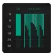
NO DIFFERENCE LOUD EVENTS dB Amplitude Incidence -8 QUILT EVENT S INPUT OUTPUTGR History
The GR History (Gain Reduction History) meter shows the current gain reduction and how it has fluctuating.
The thicker line towards the left of the display shows how much gain reduction is currently being used, while the thinner lines to its right show how this has been changing over the past second.
Presets
Factory presets are included in the plug-in installation, installed in the following locations:
Mac:
ibrany/Application Support/Solid State Logic/SSLNative/Presets/XComp
Windows 64-bit:
C:\ProgramData\Solid State Logic\SSL Native\Presets\XComp

Switching between presets can be achieved by clicking the left/right arrows in the preset management section of the plug-in GUI, and by clicking on the preset name which will open the preset management display.
Preset Management Display

text_image
File Load Save As... Save as Default Copy Copy A to B Copy B to A Factory Presets Bass Presets Vocal Presets Drum Presets Guitar Presets Default PresetThere are a number of options in the Preset Management Display:
- Load allows loading of presets not stored in the locations described above.
- Save As... allows for storage of user presets.
- Save as Default assigns the current plug-in settings to the Default Preset.
- Copy A to B and Copy B to A assigns the plug-in settings of one comparison setting to the other.
A-B Comparisons

The A B buttons at the base of the screen allows you to load two independent settings and compare them quickly. When the plug-in is opened, setting A is selected by default. Clicking the A or B button will switch between setting A and setting B.
UNDO and REDO functions allow undo and redo of changes made to the plug-in parameters.
5. X-EQ 2
INTRODUCTION
X-EQ 2 is a highly configurable 24-band EQ plug-in, featuring unique 'anti-cramping' algorithms for an unparalleled open and transparent sound. It's the ultimate EQ toolkit, with up to 17 different EQ types and filter shapes available derived from a wide variety of vintage analogue equipment. Each of the 24 bands is switchable between bell, shelf, low pass or high pass filter types, with both classic and customisable shapes available for each band. The illustration below introduces the X-EQ 2 plug-in features, described in full over the following pages.

text_image
Above the main plug-in window is a set of controls that are specific to your host application. Please refer to your host application's user guide for guidelines on using these controls Input level metering and control Bypass for smooth in/out comparisons Built-in FFT analyser post-EQ Output level metering and control Switches between Serial and Parallel signal-flow Interactive EQ display with draggable nodes Switch between main and alternative plug-in settings Left/Right and Mid/Side spatial processing modes Phase and Step response graphs INTERFACE OVERVIEWINTERFACE OVERVIEW
GETTING STARTED
The initial state of X-EQ 2 is without any frequency bands created. To add a frequency band, double-click with the mouse anywhere on the graphical interface. This will create a frequency band node at the click-point, with a curve type dependant on where you clicked on the graphical interface - this can be changed after the node has been created. X-EQ 2 can have up to 24 nodes.
text_image
Pre-01.03 Current 4.0The node can be dragged around the graphical interface to adjust the gain and frequency of the band, whilst using the mouse-wheel to adjust the band Q factor. To lock the frequency of a node, hold down shift; this is useful for changing the gain or Q factor / roll-off of a node, without changing the frequency.
Alternatively, you can use the Puck Control.
The Puck Control
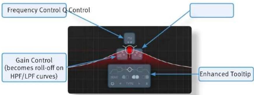
X-EQ 2 features a brand new user interface element called the Puck Control. When a frequency node is created, the frequency, Q factor, and gain (or roll off on high-pass/ low-pass filters) for that node are displayed around it and can be adjusted by clicking and dragging on the parameter. The Puck Control display will disappear when not in use to leave a clean and uncluttered plug-in window; to bring it back, simply click on the node again.
text_image
Frequency Control Q Control Gain Control (becomes roll-off on HPF/LPF curves) Enhanced Tooltip
Double-clicking on the frequency, Q, or gain section of the Puck control will open up the numerical entry for that parameter. The gain / roll off values can be entered on the left side of the EQ graph, the frequency and Q on the bottom of the EQ graph.
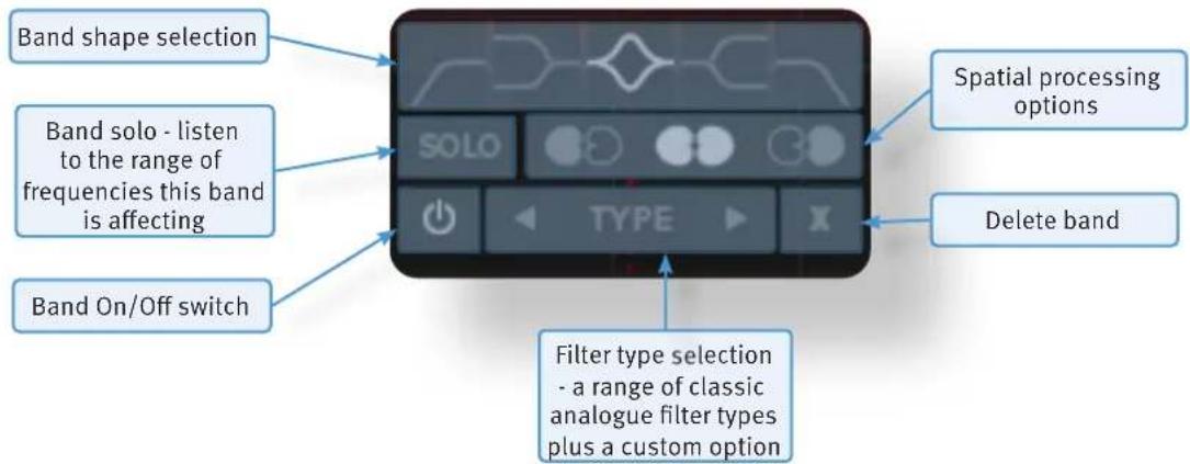
Clicking on the node will also open an Enhanced Tooltip for that frequency band. From the Enhanced Tooltip, the EQ shape and filter type can be selected, as well as the band solo enable and spatial processing options. The ‘power’ icon is a band bypass for quick A/B, whilst the cross (or ‘X’ icon) deletes the band.
text_image
Band shape selection Band solo - listen to the range of frequencies this band is affecting Band On/Off switch SoLO TYPE Spatial processing options Delete band Filter type selection - a range of classic analogue filter types plus a custom optionSpatial Processing Options
At the bottom of the plug-in window, there are two spatial processing options; Left/Right and Mid/Side.

When Left/Right mode is enabled (the default mode when initialising the plug-in) the following icons are displayed in the Enhanced Tooltip:

This option applies the EQ band to both left and right (a standard stereo EQ).
This option applies the EQ band to the left side only.

This option applies the EQ band to the right side only.
With Mid/Side mode enabled, these icons change (as shown):

This option applies the EQ band to both mid and side (a standard stereo EQ).
This option applies the EQ band to the mid signal only.

This option applies the EQ band to the side signal only.
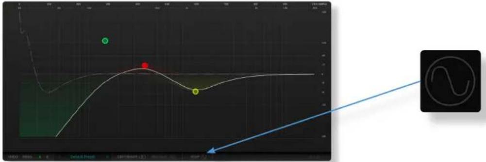
When a spatial processing option is selected (either left-only, right-only, or mid-only or side-only), the icon is displayed on the node for easy reference.

natural_image
Abstract curved line with two colored dots on a dark grid background (no text or symbols)Mid/Side, otherwise known as Sum and Difference, is a two channel format. Rather than each of the two channels carrying either the Left or Right side of a stereo signal, the Mid (or Sum) carries all signals common to both left and right channels (typically elements panned centre), and the Side (or Difference) carries all signals 'on the sides'. The Mid/Side format can be derived from a stereo left and right signal, and can be turned back into a stereo signal. This allows for some really cool spatial processing techniques when processing the Mid and Side signals differently, then recombining them back to a stereo signal - this has been a crucial mastering technique for years!
Band solos
Each frequency band can be solo'd; this allows you to listen to only the frequencies that band is affecting and the effect of the EQ curve on those frequencies. This is particularly useful for honing in on problem frequencies, and can be used to great effect when combined with the Mid/Side mode!
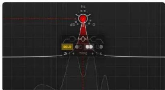
text_image
Hz dB 50.0 TYPE KTip: Pressing the Shift Key whilst dragging a node will lock it to that frequency, allowing for precision notching of resonant frequencies.
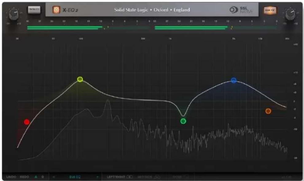
EQ Graph Display
The EQ graph provides a visualisation of several elements:
line
| Time | Value | |------|-------| | 0 | -10 | | 100 | 8 | | 200 | -4 | | 500 | 6 | | 1000 | -2 |- The coloured shade areas show the impact of each individual node.
- The white line across the graph shows the resultant EQ curve from all frequency band nodes.
- With the Analyse switch enabled, an FFT display of the post-EQ signal is shown within the EQ graph. If a band solo is enabled, you will see this on the analyser.
There are two additional responses that can be displayed on the EQ graph; the phase response and the step response. These are shown by clicking on the icon at the bottom of the plug-in window.
Phase Response Graph
The phase response shows the degree of phase shift across the frequency range of X-EQ 2. Click on the icon once to display the phase response on the EQ graph display.

line
| Point | Value | |-------|-------| | Green | -10 | | Red | -8 | | Yellow | -6 |All frequency bands cause some degree of phase shift; this does not audibly affect a mono audio source in isolation, but does affect the way two sources with similar audio content combine (two drum overhead microphones, for example). Whilst ‘phase issues’ are something to be wary of, slight phase adjustments at some frequencies can be desirable, causing cancellation at unwanted frequencies (room mode build-up, for example), and rigidity at desirable frequencies (the root notes of a bass instrument, for example).
The phase response graph can be used as a technical aid on critical EQ'ing tasks during mixing or mastering.
Step Response Graph
The step response graph shows the effect your EQ choices are having on the step response of the audio signal. Click on the icon twice to display the step response on the EQ graph display (this function toggles between 'None', 'Phase', and 'Step'.
line
| Time | Value | |------|-------| | 0 | 100 | | 200 | 50 | | 400 | 30 | | 600 | 20 |Different filters types have different effects on the step response/transients of your audio signal; some filters slow transients down (something called ‘transient slewing’), others are more transparent. Transient slewing is not necessarily a bad thing, it can have desirable effects; many vintage analogue audio circuits cause a great deal of transient slewing that was undoubtedly part of the sound!
The step response graph can help you make better informed mix decisions about which filter type is better for the task in hand.
EQ PARAMETER VALUES
| Band Gain / | Roll-off Frequency Q | ||
| High-pass filter o | - 48dB/ octave, 6dB steps 20Hz - 20kHz 0.3 - 10.3 | ||
| Low-pass filter o | - 48dB/ octave, 6dB steps 20Hz - 20kHz 0.3 - 10.3 | ||
| Low shelf +-20dB 20Hz - 20kHz 0.3 - 10.3 | |||
| High shelf +-20dB 20Hz - 20kHz 0.3 - 10.3 | |||
| Parametric Bell +-20dB 20Hz - 20kHz 0.3 - 10.3 | |||
Input and Output Sections
The input and output sections at the top of the plug-in window provide input and output gain control and metering.

text_image
Digital audio workstation timeline interface showing track numbers and time markers- When clipping occurs, the meter will turn red. It will remain red until the meter is reset by clicking on the meter.
- Turn the GAIN knob in the input section to control the level of the incoming audio signal. The post-gain signal level is shown on the input meter,
- Turn the GAIN knob in the output section to ensure that the signal retains a good signal level post-processing. The output signal level is shown on the output meter.
Interface Techniques
The basic interface techniques for the X-EQ 2 are largely identical to those for the Channel Strip. In addition to these basic techniques, the following are also available:
To control Input and Output levels, click and drag upwards or downwards.
To enter a precise value for any parameter, double-click on the parameter, enter a value on your computer keyboard and press the Return key.
Automation
Every plug-in parameter can be automated in host applications that support automation. The method for recording and editing automation varies from host to host. For specific instructions on using automation within the host, consult the host application's documentation.
Plug-in Bypass
The In/Out switch located above the Input section provides a plug-in bypass. This allows for smooth In/Out comparisons by triggering the host application's Bypass function.
The button must be 'lit' for the plug-in to be in circuit.
Presets
Factory presets are included in the plug-in installation, installed in the following locations:
Mac:
library/Application Support/Solid State Logic/SSLNative/Presets/X-EQ2
Windows 64-bit:
C:\ProgramData\Solid State Logic\SSL Native\Presets\X-EQ2

Switching between presets can be achieved by clicking the left/right arrows in the preset management section of the plug-in GUI, and by clicking on the preset name which will open the preset management display.
Preset Management Display
There are a number of options in the Preset Management Display:

text_image
File Load Save As... Save as Default Copy Copy A to B Copy B to A Factory Presets Bass Presets Vocal Presets Drum Presets Guitar Presets Default Preset- Load allows loading of presets not stored in the locations described above.
- Save As... allows for storage of user presets.
- Save as Default assigns the current plug-in settings to the Default Preset.
- Copy A to B and Copy B to A assigns the plug-in settings of one comparison setting to the other.
A-B Comparisons
The A B buttons at the base of the screen allows you to load two independent settings and compare them quickly. When the plug-in is opened, setting A is selected by default. Clicking the A or B button will switch between setting A and setting B.

UNDO and REDO functions allow undo and redo of changes made to the plug-in parameters.
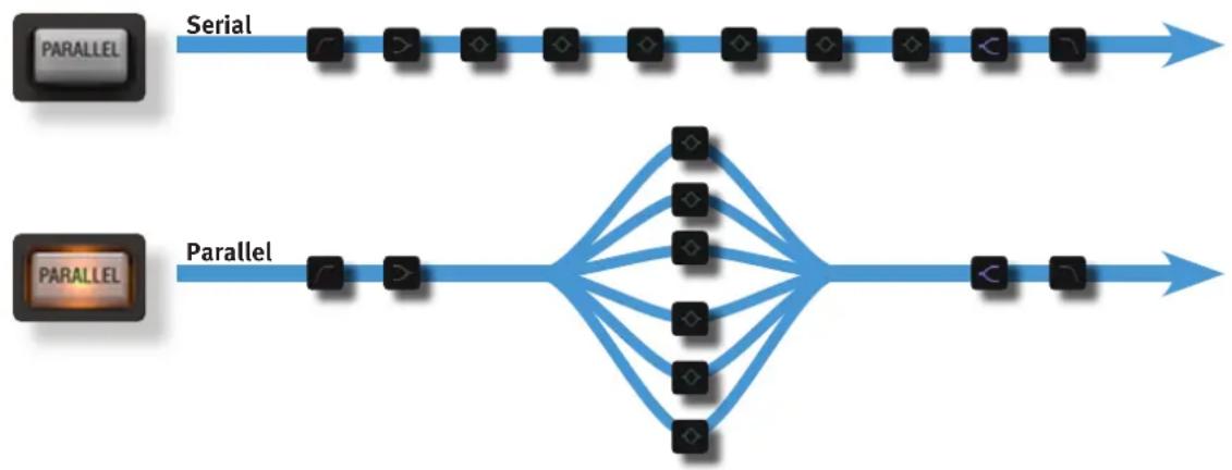
Parallel
The parallel switch changes the order in which the bell-shaped bands are processed. In normal (serial) mode they are processed one after the other. In parallel mode, once the signal has passed through LF filter and shelf bands, it is split off and routed through each bell band simultaneously before being combined again for the HF shelf and filter bands:
flowchart
graph LR
    A["Parallel"] --> B["Serial"]
    B --> C["Node 1"]
    B --> D["Node 2"]
    B --> E["Node 3"]
    B --> F["Node 4"]
    B --> G["Node 5"]
    B --> H["Node 6"]
    B --> I["Node 7"]
    B --> J["Node 8"]
    B --> K["Node 9"]
    B --> L["Node 10"]
    B --> M["Node 11"]
    B --> N["Node 12"]
    B --> O["Node 13"]
    B --> P["Node 14"]
    B --> Q["Node 15"]
    B --> R["Node 16"]
    B --> S["Node 17"]
    B --> T["Node 18"]
    B --> U["Node 19"]
    B --> V["Node 20"]
    W["Parallel"] --> X["Parallel"]
    X --> Y["Node 1"]
    X --> Z["Node 2"]
    X --> AA["Node 3"]
    X --> AB["Node 4"]
    X --> AC["Node 5"]
    X --> AD["Node 6"]
    X --> AE["Node 7"]
    X --> AF["Node 8"]
    X --> AG["Node 9"]
    X --> AH["Node 10"]
    X --> AI["Node 11"]
    X --> AJ["Node 12"]
    X --> AK["Node 13"]
    X --> AL["Node 14"]
    X --> AM["Node 15"]
    X --> AN["Node 16"]
    X --> AO["Node 17"]
    X --> AP["Node 18"]
    X --> AQ["Node 19"]
    X --> AR["Node 20"]
The parallel EQ is modelled on the old ‘Parallel Passive’ EQ units and the different style of band interaction means that the EQ performs quite differently. See the EQ History section for more information.
What is anti-cramping?
You will have noticed the phrase 'anti-cramping' in our references to X-EQ 2 and may be wondering "what is this and why should I care?" Well let us explain...
All digital audio systems have a finite frequency bandwidth dependant on the sample rate. The upper limit of this frequency bandwidth is known as the Nyquist frequency.
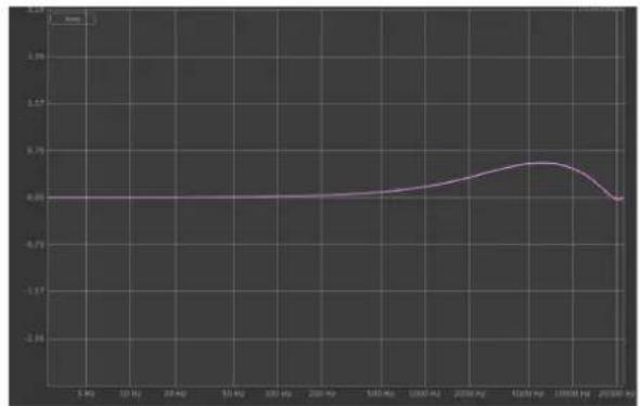
At the most commonly used DAW session sample rates of 44.1 kHz and 48 kHz, the upper limit of the frequency bandwidth is close to audible range of the human ear (22.05 kHz /24 kHz). In a traditional digital EQ design, as you approach this upper limit a phenomenon called 'cramping' or 'wrapping' occurs, whereby bell-shaped boosts or cuts at the upper-end of the frequency spectrum (around 15 - 20 kHz) begin to suffer and become affected. The effect of EQ cramping may not always be immediately obvious but listen more carefully and you will hear distortion, ringing and other artefacts that make an EQ sound unpleasant e.g. lack of smoothness in the top end. This can be particularly frustrating when trying to get some nice 'air' out of a vocal to name one real-world example. Or perhaps, you are trying to add some overall brightness/air to the whole mix.
The solution that most manufacturers use to get around this issue is to implement ‘oversampling’; the audio entering the digital processor (in this case, the plug-in) is upsampled to a higher sample rate, processing is applied without the audible cramping issue as the upper bandwidth limit has moved further away from the audible frequency range, and then downsampled back to the original sample rate. Whilst this works, it’s often at the expense of CPU usage for the user in their DAW and therefore ‘costs’ a lot more processing power.
X-EQ 2 uses SSL's own proprietary 'anti-cramping' algorithms to prevent the unpleasant artefacts of EQ cramping, particularly those which cause asymmetrical response curves for bell boosts at around 15 -20kHz. Unlike standard digital anti-cramping, SSL's proprietary solution achieves this without any additional CPU cost. How do we do this? Well, you'd have to ask our DSP experts and I think they are quite keen to keep this one a secret...
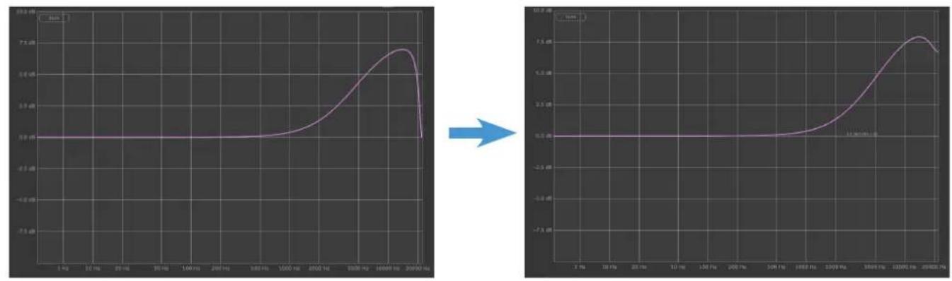
Frequency response of a cramped EQ at 44.1kHz
Frequency response of de-cramped X-EQ 2 at 44.1kHz

line
| Date | Value | | ---------- | ----- | | 04 Mar | 0.00 | | 10 Mar | 0.00 | | 20 Mar | 0.00 | | 30 Mar | 0.00 | | 1 May | 0.00 | | 2 May | 0.00 | | 3 May | 0.00 | | 10 May | 0.00 | | 20 May | 0.00 | | 30 May | 0.00 | | 12 May | 0.00 | | 22 May | 0.00 | | 32 May | 0.00 | | 1 May | 0.28 | | 2 May | 0.28 | | 3 May | 0.28 | | 12 May | 0.28 | | 22 May | 0.28 | | 32 May | 0.28 | | 1 July | -3.36 | | 2 July | -3.36 |
line
| Date | Value | | ---------- | ----- | | 5 Aug | 0.00 | | 10 Aug | 0.00 | | 24 Aug | 0.00 | | 31 Aug | 0.00 | | 5 Feb | 0.00 | | 10 Feb | 0.00 | | 20 Feb | 0.00 | | 3 Jan | 0.00 | | 6 Mar | 0.00 | | 12 May | 0.00 | | 20 May | 0.00 | | 31 May | 0.00 | | 4 Dec | 0.00 | | 11 Dec | 0.75 | | 18 Dec | 0.75 | | 21 Dec | 0.00 |Phase response of a cramped EQ at 44.1kHz
Phase response of de-cramped X-EQ 2 at 44.1kHz
EQ AND FILTER SHAPES (CLASSIC CURVES)
Bell Shapes
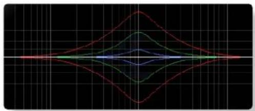
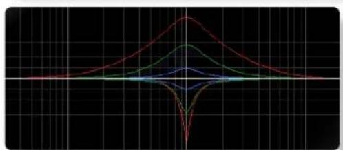
Q Definitions:
P - 3dB
Classical definition where Q is measured 3dB below peak for boost or 3dB above peak for cut.
0 - 3dB
Definition used for bells in some US products, the bandwidth for Q calculation is measured 3dB below odB line for cut or 3dB above for boost. Q in both definitions correct only for +6dB boost/cut.
P/2
New 'musical' definition based on the bandwidth measurement in the middle of a bell filter, between peak and odB line.
Normalisation 12 equalisers are normalised to have exactly the same bell shape for +6dB boost.
natural_image
Abstract line chart with red, green, and blue curves on a black grid background (no text or symbols)Classic Symmetrical (Classic Sym)
The most popular parametric EQ shape used in various mixing consoles and outboard gear. Almost constant Q characteristic.
P - 3dB
line
| X | Red Line | Green Line | Blue Line | Purple Line | |---|---|---|---|---| | 0 | 0 | 0 | 0 | 0 | | 1 | 0.5 | 0.3 | 0.2 | 0.1 | | 2 | 1.0 | 0.6 | 0.4 | 0.2 | | 3 | 1.5 | 0.9 | 0.6 | 0.3 | | 4 | 2.0 | 1.2 | 0.8 | 0.4 | | 5 | 1.5 | 1.0 | 0.7 | 0.3 | | 6 | 1.0 | 0.8 | 0.6 | 0.2 | | 7 | 0.5 | 0.6 | 0.4 | 0.1 | | 8 | 0.0 | 0.3 | 0.2 | 0.0 | | 9 | -0.5 | 0.1 | 0.1 | -0.1 | | 10 | -1.0 | -0.1 | -0.1 | -0.2 | | 11 | -1.5 | -0.3 | -0.2 | -0.3 | | 12 | -2.0 | -0.5 | -0.3 | -0.4 | | 13 | -1.5 | -0.7 | -0.4 | -0.5 | | 14 | -1.0 | -0.9 | -0.5 | -0.6 | | 15 | -0.5 | -1.1 | -0.6 | -0.7 | | 16 | 0 | -1.3 | -0.7 | -0.8 | | 17 | 0.5 | -1.5 | -0.8 | -0.9 | | 18 | 1.0 | -1.7 | -0.9 | -1.0 | | 19 | 1.5 | -1.9 | -1.0 | -1.1 | | 20 | 2.0 | -2.1 | -1.1 | -1.2 | | 21 | 1.5 | -1.9 | -1.0 | -1.1 | | 22 | 1.0 | -1.7 | -0.9 | -1.0 | | 23 | 0.5 | -1.5 | -0.8 | -0.9 | | 24 | 0.0 | -1.3 | -0.7 | -0.8 | | 25+ | -0.5 | -1.1 | -0.6 | -0.7 | The chart displays a line graph with five data series: 'Red Line' and 'Green Line'. The x-axis represents time or sequence from 'Start' to 'End', and the y-axis represents a numerical value of the corresponding series at each point on the graph's axis.Classic Asymmetrical (Classic Asym)
Often features in older equalisers. Boost as above but much narrower cut characteristic.
P - 3dB boost
0 - 3dB (x2) cut
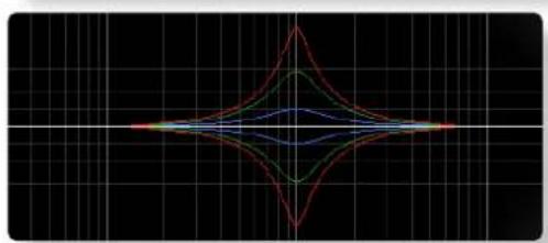
natural_image
Symmetrical abstract line pattern with red, green, blue, and yellow curves on a black grid background (no text or symbols)Proportional 1 (Prop 1)
Proportional equalisers are recognised as being more ‘musical’ than Constant Q. The bells are wider below +6dB and narrower above +6dB (or -6dB for cut).
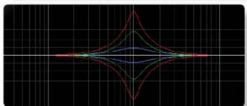
natural_image
Symmetrical abstract line pattern with red, green, blue, and yellow curves on a black grid background (no text or symbols)Proportional 2 (Prop 2)
Like Proportional 1 but with larger changes below and above +6dB peak (or -6dB for cut).
P-3dB
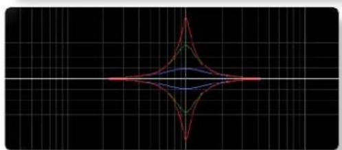
natural_image
Symmetrical abstract line pattern with red, green, and blue curves on a black grid background (no text or symbols)Proportional 3 (Prop 3)
Like Proportional 1 but with extra widened bells between 0 and +3dB (or -3dB for cut).
P - 3dB
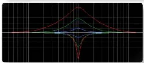
line
| X | Red Line | Green Line | Blue Line | Orange Line | |---|----------|------------|-----------|-------------| | 0 | 0.0 | 0.0 | 0.0 | 0.0 | | 1 | 0.2 | 0.3 | 0.1 | 0.4 | | 2 | 0.5 | 0.6 | 0.3 | 0.7 | | 3 | 0.8 | 0.9 | 0.5 | 1.0 | | 4 | 1.0 | 1.0 | 0.7 | 1.2 | | 5 | 0.8 | 0.9 | 0.5 | 1.0 | | 6 | 0.5 | 0.6 | 0.3 | 0.7 | | 7 | 0.2 | 0.3 | 0.1 | 0.4 | | 8 | 0.0 | 0.0 | 0.0 | 0.0 |Constant Q Asymmetrical (CQ Asym)
Used in some US products and mixers. The boost characteristics are defined according to o - 3dB formula. Extra widened between -3dB and odB.
P - 3dB boost, o - 3dB cut
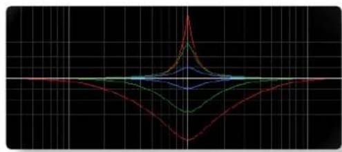
natural_image
Symmetrical waveform diagram with red, green, blue, and black lines on a grid background (no text or symbols)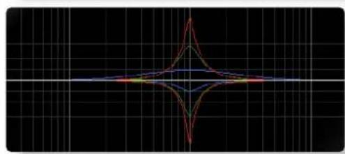
natural_image
Symmetrical waveform pattern with red, green, and blue lines on black grid background (no text or symbols)
line
| X | Y1 | Y2 | Y3 | Y4 | |---|----|----|----|----| | 0 | 0 | 0 | 0 | 0 | | 1 | 0.5| 0.3| 0.7| 0.2| | 2 | 1.0| 0.8| 1.2| 0.6| | 3 | 1.5| 1.2| 1.8| 1.0| | 4 | 2.0| 1.8| 2.5| 1.5| | 5 | 2.5| 2.2| 3.0| 2.0| | 6 | 3.0| 2.8| 3.5| 2.5| | 7 | 3.5| 3.2| 4.0| 3.0| | 8 | 4.0| 3.8| 4.5| 3.5| | 9 | 4.5| 4.2| 5.0| 4.0| | 10| 5.0| 4.8| 5.5| 4.5| | 11| 5.5| 5.2| 6.0| 5.0| | 12| 6.0| 5.8| 6.5| 5.5| | 13| 6.5| 6.2| 7.0| 6.0| | 14| 7.0| 6.8| 7.5| 6.5| | 15| 7.5| 7.2| 8.0| 7.0| | 16| 8.0| 7.8| 8.5| 7.5| | 17| 8.5| 8.2| 9.0| 8.0| | 18| 9.0| 8.8| 9.5| 8.5| | 19| 9.5| 9.2| 10.0| 9.0| | 20| 10.0|9.8|9.5 |9.5|
natural_image
Symmetrical abstract line pattern with red, green, and blue curves on a black grid background (no text or symbols)Shelving Bands

natural_image
Abstract line graph with colored dots and a smooth curve on dark background (no text or symbols)Filter Shapes
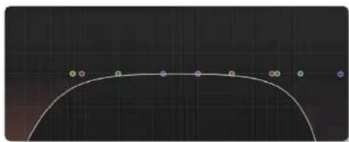
natural_image
Pure curved line diagram with colored dots along the arc, no text or symbols present
natural_image
Pure curved line diagram with colored dots along a dark grid background (no text or symbols)Constant Q Asymmetrical Reverse (CQ Asym R)
Exactly like above but with mirrored boost and cut characteristics.
Constant Q Invert (CQ Invert)
Both boost and cut characteristics are both defined according to o - 3dB formula.
$$ 0 - 3 \mathrm{dB} $$
Constant Q New (CQ New)
Defined Q is always perfectly maintained independent of bell gain (also below 6dB). In terms of P - 3dB definition of this equaliser can be classified as proportional.
$$ P / 2 $$
Parallel
Note this is accessed via the Parallel switch, not the drop-down menu.
Recreates the passive LC parallel equaliser with all its advantages (sound) and disadvantages (band interaction, asymmetry). As found in graphic equalisers.
3dB boost, 0 - 3dB (x2) cut
Low and High shelves
Q value is used to control overshoot characteristic. On the left is the Low shelf filter with a low Q value, on the right the High shelf filter exhibits overshoot with a large Q value.
Note that there are no alternative shapes for shelving bands
Critical
'Critical Damped' filters simulate a chain of passive analogue RC (for high cut) and CR (for low cut) stages fixing a behaviour similar to a series of RC elements in vintage analogue equipment.
Bessel
Linear phase behaviour leads to no overshoot or ringing resulting from a sudden transition between signal levels. The drawback is a sluggish roll-off rate.
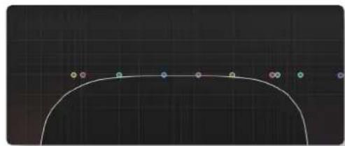
natural_image
Pure curved line diagram with colored dots along a grid background (no text or symbols)Gaussian
No ringing or overshoot in the time domain, but slow roll-off in the frequency domain.
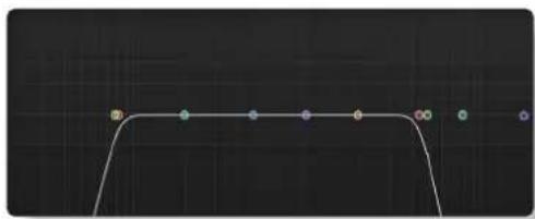
natural_image
Abstract line drawing with colored dots and a curved path on dark background (no text or symbols)Butterworth
Characterised by having a maximally flat magnitude response, i.e. no amplitude ripple in the passband.

natural_image
Pure electrical circuit lines without any symbolsChebychev
Characterised by having an equiripple magnitude response, meaning the magnitude increases and decreases regularly from DC to the cutoff frequency.
EQ HISTORY
An Audio Engineer's Best Friend
The equaliser is the oldest and the most popular sound processing tool. From the earliest days, its main function has been to correct or enhance sound by cutting or boosting certain frequency ranges. Engineers have developed countless equalisers for over 50 years, some of which became legendary and were considered bench mark equipment in studios. The most popular type of EQ in recording and post-production studios is the parametric equaliser or PEQ. It offers maximal flexibility due to direct access to all relevant filter parameters. Properly used, the PEQ is a very powerful tool and the best friend of every sound engineer in the battle for perfect sound. If misused, it can be the greatest enemy of any recording.
The Best of the Analogue and Digital Worlds
X-EQ 2 is a creative equalising tool combining the best of both the analogue and digital worlds. We recreated the most legendary analogue equalisers and added a few experimental characteristics only possible in the digital domain. By using proprietary filter algorithms, we have achieved a huge dynamic range as well as extremely low noise and distortion levels; and thus an unparalleled sound purity impossible with any analogue circuitry.
Analogue Parametric EQ Modelling
In today's era of digital audio workstations, hundreds of software parametric equalisers are available. Many of them are intended to be “THE best sounding equaliser ever”. The truth is that only a few of them are recognised and adored by the experts. You may ask why one equaliser sounds great while another does not. This question is almost as old as the equaliser itself and still is not completely answered. On the one hand there are some obvious rules that must be followed when designing a good sounding PEQ, on the other hand there are some never really proven esoteric claims driven by marketing departments or self-nominated audio evangelists. Especially treasured analogue equalisers are considered by some people as being absolutely unique and unmatched by any ‘dirty’ digital equaliser. The truth is that with a properly designed, fully parametric analytic EQ every amplitude and phase characteristic of any other equaliser setup can be recreated. Of course, the contribution of distortions to the specific sound of a particular analogue equaliser caused by the respective electronics has to be considered. If the distortions are ‘good’, they may make certain applications sound better. Usually however, ‘bad’ non linear distortions and other deficiencies like limited dynamic range are surely not responsible for a ‘magic’ sound. Therefore, our policy in digital PEQ design has always been to make the equaliser filters as precise and clean as possible. For controlled generation of distortion we recommend using enhancers or other specialised processors with proper built-in anti-aliasing technology.
Non Linear-phase EQ
Phase shift in equipment is probably one of the most misunderstood topics in audio. Phase shifts often get blamed for anything that is not classed as typical distortion. The reality is that all analogue EQs produce a deviation from linear phase that is specifically related to the shape of the EQ curve, and it is precisely these phase changes that produce the required adjustments. This is a very natural process which can be found in the audio characteristics of rooms, materials and elsewhere.
Though it is not possible for us to detect phase in isolation, the phase shift of an EQ can often be the cause of the 'magical' sound of that device once the EQ signal is added back into the mix. For example, the SSL Native channel EQ derived from the SSL analogue consoles = plenty of phase shift and plenty of magic!
In contrast, a linear-phase EQ delays all frequencies by the same amount. This can only be achieved in the digital domain by using special techniques. While this process is very effective in certain situations (e.g. ‘surgically’ removing troublesome frequencies), it should not be considered as a superior tool for the majority of EQ tasks.
Linear-phase equalisers have become popular over the past few years due to the proliferation of powerful digital processors. We decided not to go down that route with X-EQ 2 and we think you'll agree with that decision. Maybe linear-phase EQ is something we will explore in the future, but... who knows? An equaliser not only changes the relative frequency balance of a signal but also its phase. If you EQ a sound until it sounds right or natural, then the chances are that you are EQ'ing to make it sound in phase with the rest of the mix. We need say no more on this subject.
Parallel Passive EQ
Parallel EQ exhibits quite different sonic properties to the familiar serial parametric EQ. We are generally used to hearing the effect of one EQ band superimposed on another, as opposed to the band interaction inherent to a parallel EQ. Because the bands are placed in a parallel configuration, phase cancellations and re-enforcements happen that are not always obvious when first encountered.
Passive EQ is something that is found in old equaliser units and is generally known for its transparent and natural sound, but has some problems associated with it. However, in the digital domain these shortcomings do not have such an influence.
A passive EQ does not have any gain elements, but can still have controls to seemingly boost frequencies as well as cut. What actually happens is that the entire signal is cut by an amount, but the frequencies that are apparently ‘boosted’ are simply not cut as much. Therefore the unit must attenuate either the input, the output, or both to allow enough headroom.
Unfortunately, in the analogue domain, a 20dB reduction in signal level produces a 20dB increase in the noise floor. Luckily in the digital domain, with a 64-bit floating point DSP, these issues do not remain.
In X-EQ 2 – when the ‘parallel’ button is engaged – you are presented with a parallel passive EQ model that the original designers of these devices could only have dreamed of. The noise floor can be disregarded due to the huge resolution available in SSL Native plug-ins.
You may find yourself entering this mode more and more as you become familiar with the sonic signature. Larger gain changes are possible without colouration, and boost starts to become something that is usable to a significant degree in a digital EQ!
Parallel EQ does exhibit asymmetry in its boost and cut characteristics. But this is not such a bad thing as most engineers would agree that boost is best done with low (wide) Q values and cut with a higher (narrower) Q.
6. Vocalstrip 2
INTRODUCTION
Vocalstrip is a collection of refined tools for superior vocal processing. The illustration below introduces the main Vocalstrip plug-in features which are described in full over the following pages.

text_image
Bypass De-Ploser De-Esser Displays Displays FFT Analyser & EQ Graph Input Level & Metering Vocalstrip 2 Solid State Logic • Oxford • England SSL NATIVE Output Level & Metering Compander Displays Preset Management Compressor & Expander (Compander) De-Esser De-Ploser 3-Band EQ Default Price IE Ester IE Ploser Equaliser E Compander Processing OrderINTERFACE OVERVIEW
The basic interface techniques for the Vocalstrip are largely identical to those for the Channel Strip.
Plug-in Bypass

The switch located above the Input section provides a plug-in bypass. This allows for smooth In/Out comparisons by triggering the host application's Bypass function.
The button must be 'lit' for the plug-in to be in circuit.
Presets
Factory presets are included in the plug-in installation, installed in the following locations:
Mac:
ibrary/Application Support/Solid State Logic/SSLNative/Presets/Vocalstrip2
Windows 64-bit:
C:\ProgramData\Solid State Logic\SSL Native\Presets\Vocalstrip2

Switching between presets can be achieved by clicking the left/right arrows in the preset management section of the plug-in GUI, and by clicking on the preset name which will open the preset management display.
Preset Management Display
There are a number of options in the Preset Management Display:
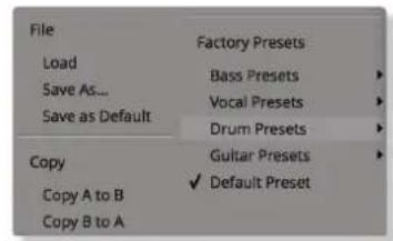
text_image
File Load Save As... Save as Default Copy Copy A to B Copy B to A Factory Presets Bass Presets Vocal Presets Drum Presets Guitar Presets Default Preset- Load allows loading of presets not stored in the locations described above.
- Save As... allows for storage of user presets.
- Save as Default assigns the current plug-in settings to the Default Preset.
- Copy A to B and Copy B to A assigns the plug-in settings of one comparison setting to the other.
A-B Comparisons

The A B buttons at the base of the screen allows you to load two independent settings and compare them quickly. When the plug-in is opened, setting A is selected by default. Clicking the A or B button will switch between setting A and setting B.
UNDO and REDO functions allow undo and redo of changes made to the plug-in parameters.
Automation
Automation support for Vocalstrip is the same as for the Channel Strip.
Input and Output Sections
The input and output sections at the top of the plug-in window provide input and output gain control and metering.

text_image
30 27 24 21 18 15 12 9 6 5 4 30 27 24 21 18 15 12 9 6 5 4- When clipping occurs, the meter will turn red. It will remain red until the meter is reset by clicking on the meter.
- Turn the GAIN knob in the input section to control the level of the incoming audio signal. The post-gain signal level is shown on the input meter,
- Turn the GAIN knob in the output section to ensure that the signal retains a good signal level post-processing. The output signal level is shown on the output meter.
VOCALSTRIP MODULES
De-esser
Sibilance is often found in vocal recordings whereby the 'S' consonants are too pronounced. The Vocalstrip de-esser can detect and remove sibilance.
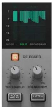
text_image
MODE : SPLIT BROADSAND DE-ESSER THRESHOLD FREQUENCY LOOK AHEAD LISTEN- Switch the de-esser on by clicking on the power button in its top left-hand corner.
- Adjust the Threshold control to set the detection level. You will see the gain reduction meter above the de-Esser controls change depending on where this is set.
- Adjust the Frequency knob to change the frequency range that triggers the de-esser.
- To listen to the sibilance that is being removed, press the Listen button. This can be particularly helpful in ensuring that the threshold is correctly set.
- Turn on the Lookahead to detect incoming sibilance before it reaches the de-esser block - this increases latency, but results in a smoother sound. Ensure Lookahead is turned off if monitoring live inputs through Vocalstrip.
- The de-esser runs in SPLIT band mode by default (gain reduction is applied to the frequency range that triggers it), but can be switched to BROADBAND mode (gain reduction is applied to the full frequency range when triggered).
De-ploser
Plosives are bursts of low frequency energy in a signal that can cause compressors to sound unpleasant. They are often caused when recording a singer too close to the microphone, or without a pop shield. The Vocalstrip de-ploser can detect and remove plosives.

text_image
MODE SPLIT BROKOSAND DE-PLOSER THRESHOLD FREQUENCY LOCK AREAD LISTEN- Switch the de-ploser on by clicking on the power button in its top left-hand corner.
- Adjust the Threshold control to set the detection level. You will see the gain reduction meter above the de-ploser controls change depending on where this is set.
- Adjust the Frequency knob to change the frequency range that triggers the de-ploser.
- To listen to the plosives being removed, press the Listen button. This can be particularly helpful in ensuring that the threshold is correctly set.
- Turn on the Lookahead to detect incoming plosives before they reach the de-ploser block - this increases latency, but results in a smoother sound. Ensure Lookahead is turned off if monitoring live inputs through Vocalstrip.
- The de-ploser runs in SPLIT band mode by default (gain reduction is applied to the frequency range that triggers it), but can be switched to BROADBAND mode (gain reduction is applied to the full frequency range when triggered).
Equaliser
Switch the EQ on by clicking on the power button. Three popular EQ types are provided to allow you to cut low frequencies, find and remove resonances, and shape the top end of the signal. Switch each band on by clicking on the corresponding power switch.
- The high pass filter operates in the range of 30Hz to 300Hz, with a slight boost around its cut-off frequency.
- The notch filter operates in the range 200Hz to 10kHz and offers 12dB of boost and 36dB of attenuation with a high Q value.
- The high band EQ offers 12dB of boost/attenuation over the range of 1kHz to 20kHz with a low Q value.

text_image
EQUALISER 300 3000 dB 0.2 10 kHz dB 1 20EQ Display
When any controls within the EQ section are moved, the display in the top right-hand quarter of the window becomes an EQ graph:

line
| Date | FT | GJP | QF | |------|------|------|------| | 2019 | 0.5 | 0.3 | 0.4 | | 2020 | 0.6 | 0.4 | 0.5 |- The line across the graph shows the frequency response of the current EQ settings.
- The shaded area represents the impact of each of the three EQ bands.
- A display of the signal's frequency response is shown in green. The FFT signal displayed can be switched between the plug-in input and output and can be switched off, all using the FFT buttons above the graph.
EQ Tip: Finding and Attenuating a Resonance
Vocal resonances can be detected and reduced in the following way:
- Set the notch filter gain to +10dB.
- Sweep the frequency slowly across the frequency range, listening out for a significant build up of resonance.
- Once you have found the offending frequency, bring the gain of the notch band down.
• Another technique is to use the green frequency response line in the EQ graph and locate resonances visually.
Compander
The Vocalstrip Compander is a hybrid Compressor and Expander. Switch it on by clicking on the power button.
Expander
First the signal enters a fixed ratio downwards expander, designed to reduce room ambience, spill or breath noise that is often brought up by the subsequent compression.
To set the level at which the level reduction is introduced, turn the Exp Thresh (Expander Threshold). Turn the threshold to odB to stop the expander affecting the input signal. The amount of level reduction introduced is shown in the green bar above the Exp Thresh knob.

text_image
COMPANDER ATTACK RATIO EXP THRESH THRESHOLD SOFT KNEE DRIVE RELEASE MAKEUP GAINCompressor
The compressor offers fully variable Ratio, Thresh (threshold), Attack, Release and Makeup controls, along with a choice of Hard or Soft Knee.
The output stage, which is sourced after the make-up gain, features an optional Drive feature that introduces harmonic characteristics to the signal. Its intensity is increased with the Makeup gain. If you use a lot of make-up gain to drive the circuit, the level can be reduced again using the Output level control. The amount of level reduction introduced is shown in the red bar above the compressor controls.
Compander Display
When any controls within the Compander section are moved, the display in the top of the window shows two different graphs:
- The left-hand graph is a gain-law display, showing the relationship between input and output levels.
- The right-hand graph is an I/O difference display, showing how often each level occurs within the input and output signals. The input is shown on the left, and the output on the right.
- The vertical scale is amplitude, with odB at the top and - at the bottom. The length of each line protruding from the centre represents the number of incidents of that amplitude over a period of seconds.
- To the right of the I/O difference display are the gain reduction meters; an orange meter for the compressor, a green meter for the expander.

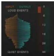
Processing Order
The processing order is controlled at the base of the plug-in window.

text_image
DE-ESSER DE-PLOSER EQUALISER COMPANDERClick on the left or right arrows to move a module earlier or later in the plug-in signal path.
7. Drumstrip
INTRODUCTION
Drumstrip is a one-stop solution for superior drum processing, providing tailor-made tools for fixing and polishing your drum sounds. The illustration below introduces its features which are described in full over the following pages.
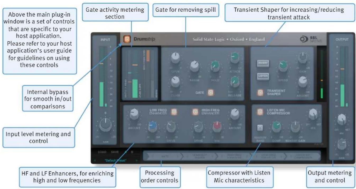
text_image
Gate activity metering section Gate for removing spill Transient Shaper for increasing/reducing transient attack Above the main plug-in window is a set of controls that are specific to your host application. Please refer to your host application's user guide for guidelines on using these controls Internal bypass for smooth in/out comparisons Input level metering and control HF and LF Enhancers, for enriching high and low frequencies Processing order controls Compressor with Listen Mic characteristics Output metering and controlINTERFACE OVERVIEW
The basic interface techniques for the Drumstrip are largely identical to those for the Channel Strip.
Plug-in Bypass

The power switch located above the Input section provides an internal plug-in bypass. This allows for smoother In/Out comparisons by avoiding the latency issues associated with the host application's Bypass function. The button must be 'lit' for the plug-in to be in circuit.
Automation
Automation support for Drumstrip is the same as for the Channel Strip.
Presets
Factory presets are included in the plug-in installation, installed in the following locations:
Mac:
ibrany/Application Support/Solid State Logic/SSLNative/Presets/Drumstrip
Windows 64-bit:
C:\ProgramData\Solid State Logic\SSL Native\Presets\Drumstrip

Switching between presets can be achieved by clicking the left/right arrows in the preset management section of the plug-in GUI, and by clicking on the preset name which will open the preset management display.
Preset Management Display

text_image
File Load Save As... Save as Default Copy Copy A to B Copy B to A Factory Presets Bass Presets Vocal Presets Drum Presets Guitar Presets Default PresetThere are a number of options in the Preset Management Display:
- Load allows loading of presets not stored in the locations described above.
- Save As... allows for storage of user presets.
- Save as Default assigns the current plug-in settings to the Default Preset.
- Copy A to B and Copy B to A assigns the plug-in settings of one comparison setting to the other.
A-B Comparisons

The A B buttons at the base of the screen allows you to load two independent settings and compare them quickly. When the plug-in is opened, setting A is selected by default. Clicking the A or B button will switch between setting A and setting B.
UNDO and REDO functions allow undo and redo of changes made to the plug-in parameters.
Automation
Automation support for Vocalstrip 2 is the same as for the Channel Strip.
INPUT AND OUTPUT SECTIONS
The input and output sections at either side of the plug-in window provide input and output gain control, along with displays of the following information:
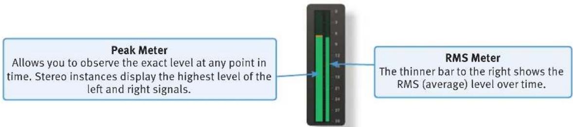
text_image
Peak Meter Allows you to observe the exact level at any point in time. Stereo instances display the highest level of the left and right signals. RMS Meter The thinner bar to the right shows the RMS (average) level over time.When clipping occurs, the meter will turn red. It will remain red until the meter is reset by clicking on the meter.
Turn the GAIN knob in the input section to control the level of the incoming audio signal. The post-gain signal level is shown above.
Turn the GAIN knob in the output section to ensure that the signal retains a good signal level post-processing. The output signal level is shown above the knob.
DRUMSTRIP MODULES
Gate
The gate is suitable for many applications, including:
- Shortening drum hits to obtain a 'tighter' sound
- Controlling ambience on live drums tracks
- Manipulating attack and decay characteristics
Switch the Gate on by clicking on the power button.
The Gate provides controls for the Attack, Release and Hold times, as well as Open and Close thresholds and Range levels, as illustrated in the diagrams below left. If you are unclear about these parameters.
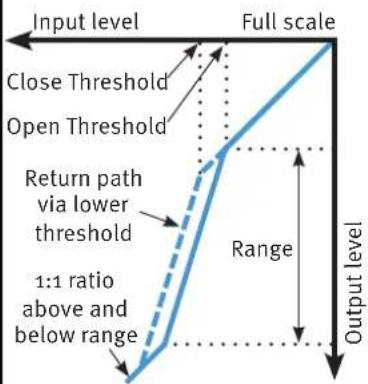
flowchart
graph TD
    A["Input level"] --> B["Full scale"]
    B --> C["Output level"]
    D["Close Threshold"] --> E["Open Threshold"]
    E --> F["Return path via lower threshold"]
    F --> G["1:1 ratio above and below range"]
    G --> H["Range"]
Open and Close Thresholds
The levels for ‘opening’ the gate to audio and ‘closing’ it again are set separately. Generally, the ‘open’ level is set higher than the ‘close’ level. This is known as hysteresis and is very useful as it allows instruments to decay more naturally. If the close threshold is higher than the open threshold, the close threshold is ignored.
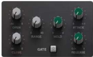
text_image
-30 OPEN 0 90 RANGE 0 4 HOLD -30 CLOSE GATE 0.1 0.1 RELEASEAttenuation level
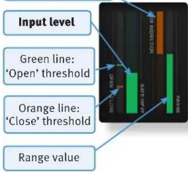
flowchart
graph TD
    A["Input level"] --> B["Green line: 'Open' threshold"]
    A --> C["Orange line: 'Close' threshold"]
    A --> D["Range value"]
    B --> E["Bar Chart with Green, Red, Orange Bars"]
    C --> E
    D --> E
    E --> F["Output: FAIR"]
    style A fill:#f9f,stroke:#333
    style B fill:#ccf,stroke:#333
    style C fill:#ccf,stroke:#333
    style D fill:#cfc,stroke:#333

line
| Time | Change in output level | |------|------------------------| | 0 | Peak (Attack) | | 1 | Hold | | 2 | Release | | 3 | Final |Range
The range is the depth of attenuation applied to the signal when the gate is closed, as indicated by the white line in the right hand column. For a true gating action the range should be set to -8odB, which is effectively silence. By reducing the range, the gate takes on some of the characteristics of a downward expander where the signal is lowered in level set by the range amount, rather than being completely silenced. This can be useful in cleaning up a drum track containing reverb, where silencing the reverb would sound too artificial but attenuating it by a
| Parameter Min Max | |
| Open Thr odB -30dB | |
| Close Thr odB -30dB | |
| Range odB -80dB | |
| Attack oms 0.1ms | |
| Hold os 4s | |
| Release os | 1s |
few dB would push it down to an acceptable level.
Transient Shaper
The Transient Shaper allows you to add attack to the start of a drum hit by increasing the amplitude of the attack portion of the signal whilst leaving the decay unchanged. The right hand waveform is a processed version of the one on the left. It has been passed through the transient shaper where the amplitude of the attack portion

text_image
INVERT LISTEN SPEED GAIN TRANSIENT SHAPER 0 100 ABOUNThas been increased.
Switch the Shaper on by clicking on the 'power' button. The meter gives visual feedback on how much attack is being added using the Gain and Amount controls. Gain controls the detection level of the controller signal, and should be set so that only the transients you want to shape are detected. If this is set too low then the Shaper will do nothing; if it is set too high then the Shaper will detect too many transients, resulting in an exaggerated process, and the attack appearing too long. The default setting of odB
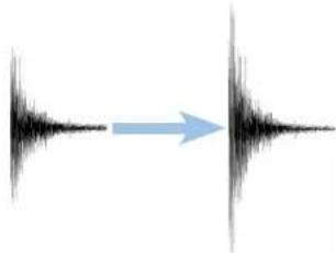
natural_image
Diagram showing a sound wave splitting into two adjacent vertical channels with a blue arrow indicating direction (no text or symbols)should be a good starting point.
Gain doesn't directly affect the output signal's gain.
Amount controls the amount of the processed signal added to the unprocessed signal. This process can increase the peak level of a signal significantly, so watch the output meter carefully.
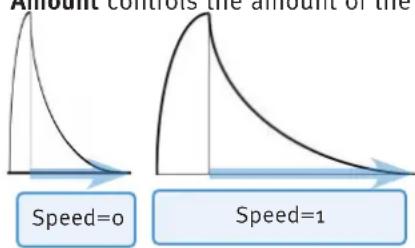
line
| Speed | Peak Value | |-------|------------| | 0 | Low | | 1 | High |Speed controls the length of time the added attack takes to fall back down to the normal signal level once it has reached the top of the attack phase. Turn the knob clockwise for a slower speed, and longer transient.
The Invert switch inverts the processed signal so that it is subtracted from the unprocessed signal. This has the effect of softening the attack, resulting in more body in the drum sound.
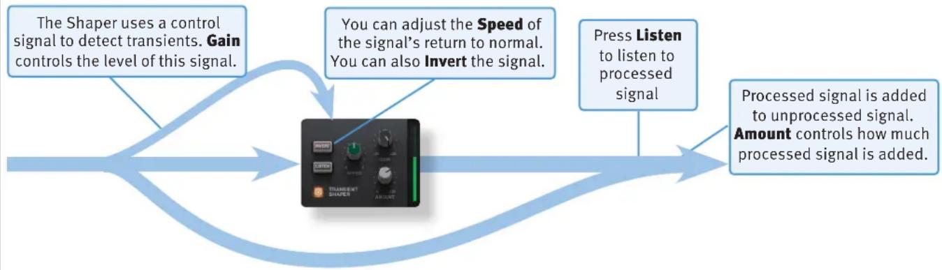
flowchart
graph LR
    A["The Shaper uses a control signal to detect transients. Gain controls the level of this signal."] --> B["You can adjust the Speed of the signal's return to normal. You can also Invert the signal."]
    B --> C["Press Listen to listen to processed signal"]
    C --> D["Processed signal is added to unprocessed signal. Amount controls how much processed signal is added."]
    D --> E["Transient Shaper with AC/DC input"]
The Listen switch allows you to listen to the processed signal, to assist in the set up process.

When the Invert and Listen buttons are both pressed, the signal will not be inverted.

HF and LF Enhancers
The HF and LF enhancers respectively enrich the high and low frequencies of the input signal. Whereas a standard EQ simply raises the level of certain frequencies, the Enhancer adds a combination of 2nd and 3rd harmonics to those frequencies, producing a more pleasing effect.
Switch each Enhancer on by clicking on the power button in its top left-hand corner. No effect is heard until an Enhancer's Drive and Amount are turned up.
HF Cutoff sets the frequency above which the HF Enhancer generates harmonics. It ranges from 2kHz up to 20kHz – To add air or sparkle to a signal, push this frequency towards the higher end
of the range. To give more presence to a signal, use the lower end of the range. Note that the effect is barely audible in the 15kHz to 20kHz range.
LF Turnover sets the frequency below which the LF Enhancer generates harmonics. It ranges from 20Hz up to 250Hz. The LF Enhancer is great for adding depth and weight to kick drums, snare or toms.
Each Enhancer has its own Drive and Amount controls:
- Drive (or overdrive) controls the density and amount of harmonic content, from 0 to 100% .
- Amount is the amount of Enhanced signal that is mixed into the unprocessed signal, from 0 to 100% .
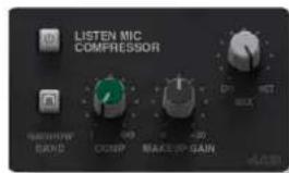
text_image
LISTEN MIC COMPRESSOR MACHINE BAND COMP MAKE UP GAINListen Mic Compressor
The Listen Mic Compressor was first found in the classic SSL 4000 E Series console. The Drumstrip edition includes a narrowband EQ bypass and a wet/dry Mix control.
Comp controls the amount of compression, from 0 to 100%.
Makeup controls the level compensation for the gain reduction and Mix controls the balance of the compressed ('Wet') to uncompressed ('Dry') signal. Note that Makeup only acts on the 'wet' part of the signal.
To simulate the original narrow-band listen mic characteristic, activate the EQ In button – to use the compressor on the full frequency range, leave EQ In deactivated.
The Listen Mic Compressor features very quick fixed time constants. This means it is easily capable of producing distortion on low frequency material.
Processing Order
The five processing blocks in Drumstrip can be configured in any order, as defined by the Process Order blocks at the base of the plug-in window.

flowchart
graph LR
    A["SATE"] --> B["TRANSIENT SHAPER"]
    B --> C["HICH FREQ ENHANCER"]
    C --> D["LOW FREQ ENHANCER"]
    D --> E["LISTEN MIC COMPRESSOR"]
To move a module within the order press either the left
arrow or the right arrow.
By default the gate is first in the chain so that it is able to act on the full dynamic range of the signal before the signal is processed by the Listen Mic Compressor.
8. X-ValveComp
INTRODUCTION
The illustration below gives an overview of some of the X-ValveComp features which are described in full over the following pages.

text_image
Above the main plug-in window is a set of controls that are specific to your host application. Please refer to your host application's user guide for guidelines on using these controls Compressor Controls Interactive compressor display with draggable nodes Hi and Lo pass filters for the compressor side-chain Internal bypass for smooth in/out comparisons Input level metering and control Valve switch for activating the valve emulation Compressor Time Constants Mix level for parallel compression Makeup gain level control Output metering and controlINTERFACE OVERVIEW
The basic interface techniques for the X-ValveComp are largely identical to those for the Channel Strip. In addition to these basic techniques, the following are also available:
To control Input and Output levels, click and drag upwards or downwards.
To enter a precise value for any parameter, double-click on its value display, enter a value on your computer keyboard and press the Return key.
Threshold and Ratio values can also be controlled directly within the Compression Law display. Move the left hand node along its diagonal line to control the Threshold, and move the right hand node up and down to control the ratio.
Automation
Automation support for X-ValveComp is the same as for the Channel Strip.
Plug-in Bypass

The In/Out switch located above the Input section provides a plug-in bypass. This allows for smooth In/Out comparisons by triggering the host application's Bypass function. The button must be 'lit' for the plug-in to be in circuit.
Presets
Factory presets are included in the plug-in installation, installed in the following locations:
Mac:
ibrany/Application Support/Solid State Logic/SSLNative/Presets/XValveComp
Windows 64-bit:
C:\ProgramData\Solid State Logic\SSL Native\Presets\XValveComp

Switching between presets can be achieved by clicking the left/right arrows in the preset management section of the plug-in GUI, and by clicking on the preset name which will open the preset management display.
Preset Management Display

text_image
File Load Save As... Save as Default Copy Copy A to B Copy B to A Factory Presets Bass Presets Vocal Presets Drum Presets Guitar Presets Default PresetThere are a number of options in the Preset Management Display:
- Load allows loading of presets not stored in the locations described above.
- Save As... allows for storage of user presets.
- Save as Default assigns the current plug-in settings to the Default Preset.
- Copy A to B and Copy B to A assigns the plug-in settings of one comparison setting to the other.
A-B Comparisons

The A B buttons at the base of the screen allows you to load two independent settings and compare them quickly. When the plug-in is opened, setting A is selected by default. Clicking the A or B button will switch between setting A and setting B.
UNDO and REDO functions allow undo and redo of changes made to the plug-in parameters.
Input and Output Levels
The input and output sections at either side of the plug-in window provide input and output gain control, along with displays of the following information:

text_image
Peak Meter Allows you to observe the exact level at any point in time. Stereo instances display the highest level of the left and right signals. RMS Meter The thinner bar to the right shows the RMS (average) level over time.When clipping occurs, the meter will turn red. It will remain red until the meter is reset by clicking on the meter.

Turn the GAIN knob in the input section to control the level of the incoming audio signal. The post-gain signal level is shown above.
Turn the GAIN knob in the output section to ensure that the signal retains a good signal level post-processing. The output signal level is shown above the knob.
Knee
The Knee controls how focussed the threshold level is:
- With a hard knee (knob at minimum) the compressor's parameters all come into force at precisely the point at which the threshold is crossed. In the Compression Law diagram, this is shown by a sharp change in gradient at the threshold.
- With a soft knee, the ratio is introduced gradually, starting below the threshold and reaching its full value above the threshold. In the Compression Law graph, this is shown by a curve in the gradient around the threshold.
- The Knee control also affects the main threshold point.
Valve In

Valve in introduces a tube compressor emulation for saturating the signal by adding harmonics.

Side-chain
Hi- and Lo-pass filters are available for the Compressor side-chain. To switch the filters into the compressor side chain, switch the S/Chain in button on. To listen to the Compressor side-chain, click on the Listen button. Adjusting the filter controls will change the signal that triggers the gain reduction; removing low-end frequencies from the side-chain can reduce unwanted pumping effects, for example.
Mix
Dry/Wet option for parallel compression.
Auto Gain

You can allow the plug-in to set the make-up gain automatically by clicking the Auto button (towards the bottom of the screen).
9. X-Saturator
INTRODUCTION
The illustration below gives an overview of some of the X-Saturator features which are described in full over the following pages.
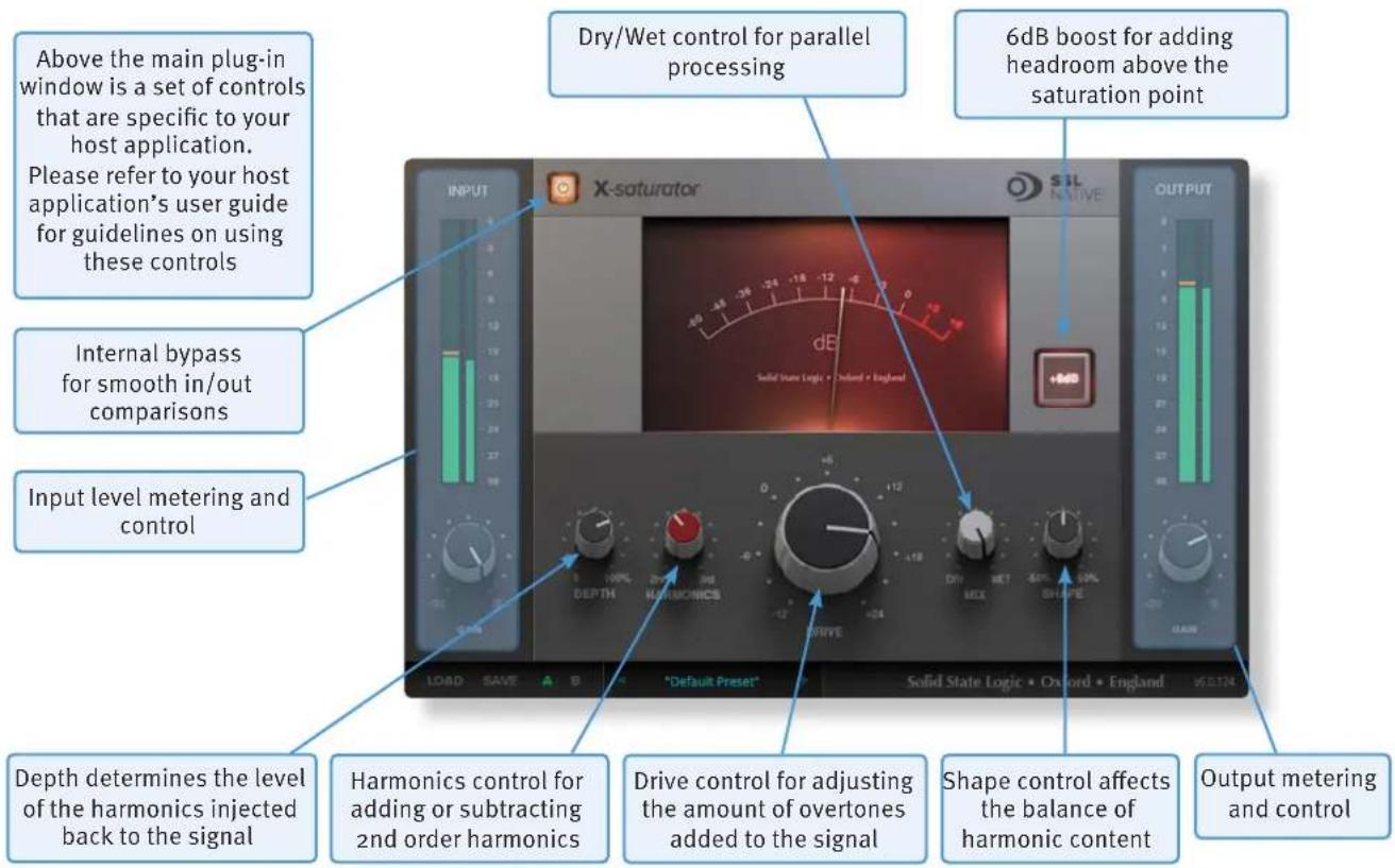
text_image
Above the main plug-in window is a set of controls that are specific to your host application. Please refer to your host application's user guide for guidelines on using these controls Dry/Wet control for parallel processing 6dB boost for adding headroom above the saturation point Internal bypass for smooth in/out comparisons Input level metering and control Depth determines the level of the harmonics injected back to the signal Harmonics control for adding or subtracting 2nd order harmonics Drive control for adjusting the amount of overtones added to the signal Shape control affects the balance of harmonic content Output metering and controlINTERFACE OVERVIEW
The basic interface techniques for the X-Saturator are largely identical to those for the Channel Strip.
Automation
Automation support for X-Saturator is the same as for the Channel Strip.
Plug-in Bypass

The power switch located above the Input section provides an internal plug-in bypass. This allows for smoother In/Out comparisons by avoiding any latency issues associated with the host application's Bypass function. The button must be 'lit' for the saturator to be in circuit (as shown).
Input and Output Levels
The input and output sections at either side of the plug-in window provide input and output gain control, along with displays of the following information:
Peak Meter
Allows you to observe the exact level at any point in time. Stereo instances display the highest level of the left and right signals.
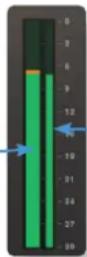
RMS Meter
The thinner bar to the right shows the RMS (average) level over time.
When clipping occurs, the meter will turn red. It will remain red until the meter is reset by clicking on the meter.

Turn the GAIN knob in the input section to control the level of the incoming audio signal. The post-gain signal level is shown above.
Turn the GAIN knob in the output section to ensure that the signal retains a good signal level post-processing. The output signal level is shown above the knob.
Boost +6dB
Will add 6dB of Headroom above your saturation point.
Drive
Dialling in the drive will determine the level of saturation that will be added.
Harmonics
By adjusting the Harmonics control the distortion characteristics can be shifted from '50s valve-style overdrive (if the control is turned fully anti-clockwise for 2nd harmonic distortion) to '70s transistor-style grit (if the control is turned fully clockwise for 3rd harmonic distortion).
Depth / Shape
Depth and Shape control the number of harmonics injected back into the signal, enriching the sound. Depth sets the amplitude of the added harmonics; at 0% no harmonics are introduced to the input signal, at 100% the full amount of generated harmonic content is introduced to the input signal. Shape will add overtones in the high frequency spectrum; -50% is subtle and smooth, +50 will sound more aggressive.
Presets
Factory presets are included in the plug-in installation, installed in the following locations:
Mac:
library/Application Support/Solid State Logic/SSLNative/Presets/XSaturator
Windows 64-bit:
C:\ProgramData\Solid State Logic\SSL Native\Presets\XSaturator

Switching between presets can be achieved by clicking the left/right arrows in the preset management section of the plug-in GUI, and by clicking on the preset name which will open the preset management display.
Preset Management Display
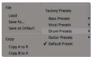
text_image
File Load Save As... Save as Default Copy Copy A to B Copy B to A Factory Presets Bass Presets Vocal Presets Drum Presets Guitar Presets Default PresetThere are a number of options in the Preset Management Display:
- Load allows loading of presets not stored in the locations described above.
- Save As... allows for storage of user presets.
- Save as Default assigns the current plug-in settings to the Default Preset.
- Copy A to B and Copy B to A assigns the plug-in settings of one comparison setting to the other.
A-B Comparisons

The A B buttons at the base of the screen allows you to load two independent settings and compare them quickly. When the plug-in is opened, setting A is selected by default. Clicking the A or B button will switch between setting A and setting B.
UNDO and REDO functions allow undo and redo of changes made to the plug-in parameters.
10. X-Phase
INTRODUCTION
The illustration below gives an overview of some of the X-Phase features which are described in full over the following pages.
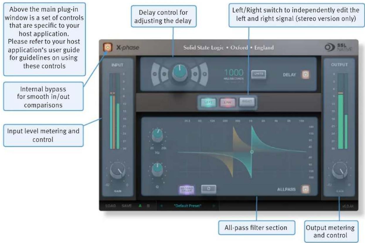
text_image
Above the main plug-in window is a set of controls that are specific to your host application. Please refer to your host application's user guide for guidelines on using these controls Delay control for adjusting the delay Left/Right switch to independently edit the left and right signal (stereo version only) X-phase Solid State Logic • Oxford • England SSL NATIVE INPUT 1000 MILI/ECONDE UNITS DELAY OUTPUT LEFT LINK RIGHT Internal bypass for smooth in/out comparisons Input level metering and control 21.3 40 125 200 300 40 50 60 70 80 90 100 110 26 20Hz 21.3 40 125 200 300 40 50 60 70 80 90 100 SECOND ORDER ALL PASS LOAD SAVE A B "Default Preset" All-pass filter section Output metering and controlINTERFACE OVERVIEW
The basic interface techniques for the X-Phase are largely identical to those for the Channel Strip.
Automation
Automation support for X-Phase is the same as for the Channel Strip.
Plug-in Bypass

The In/Out switch located above the Input section provides a plug-in bypass. This allows for smooth In/Out comparisons by triggering the host application's Bypass function. The button must be 'lit' for the plug-in to be in circuit.
Input and Output Levels
The input and output sections at either side of the plug-in window provide input and output gain control, along with displays of the following information:
Peak Meter
Allows you to observe the exact level at any point in time. There are two meters in stereo and one in mono.

RMS Meter
The thinner bar to the right shows the RMS (average) level over time.
When clipping occurs, the meter will turn red. It will remain red until the meter is reset by clicking on the meter.
Delay
Activate or deactivate a delay for the whole signal with the Delay In switch. Use the dial to set the delay in seconds, milliseconds and samples, meters or feet. The single +/- switches will give you smaller increments than the double +/- switches.

text_image
1000 MILLI SECONDS MAX. 2500 MPV UNITSAll-pass In
Activates the All-pass Filter.
All-pass Phase
Inverts the phase of the All-pass Filter.
Frequency
Sets the Frequency of the filter.
Second Order
Switches the filter between first and second order.
Q Factor
Sets the Q of the Filter, thus it will adjust the rate of phase change across the frequency spectrum.
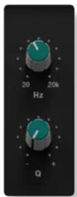
text_image
20 Hz 20k QStereo Version
Stereo versions have an additional L-R-Switch to edit stereo signals.
Presets
Factory presets are included in the plug-in installation, installed in the following locations:
Mac:
ibrany/Application Support/Solid State Logic/SSLNative/Presets/XPhase
Windows 64-bit:
C:\ProgramData\Solid State Logic\SSL Native\Presets\XPhase

Switching between presets can be achieved by clicking the left/right arrows in the preset management section of the plug-in GUI, and by clicking on the preset name which will open the preset management display.
Preset Management Display
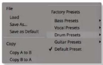
text_image
File Load Save As... Save as Default Copy Copy A to B Copy B to A Factory Presets Bass Presets Vocal Presets Drum Presets Guitar Presets Default PresetThere are a number of options in the Preset Management Display:
- Load allows loading of presets not stored in the locations described above.
- Save As... allows for storage of user presets.
- Save as Default assigns the current plug-in settings to the Default Preset.
- Copy A to B and Copy B to A assigns the plug-in settings of one comparison setting to the other.
A-B Comparisons

The A B buttons at the base of the screen allows you to load two independent settings and compare them quickly. When the plug-in is opened, setting A is selected by default. Clicking the A or B button will switch between setting A and setting B.
UNDO and REDO functions allow undo and redo of changes made to the plug-in parameters.
PHASED BY PHASE?
Phase. It's a funny subject, one that many of us think we know a bit about but unfortunately don't often fully understand how to handle all of it. The idea that two microphones, set at different distances from a guitar, will have the sound arrive at them at different times – thus making them “out of phase” with each other – is fairly simple to grasp. To fix this we could delay one of the signals by the same time it takes the sound to travel between the two microphones so that the signal arrives at the Mix bus at the same point in time. We're quite used to the idea of “flipping the phase” of a signal using a mixing console or our DAW to try and get two signals aligned; therefore, sounding better. What this does is to change the phase of the signal by 180°, or to reverse the polarity of it; essentially “turning your waveform upside down”. We're also used to aligning audio files so that peaks of layered sounds all happen at exactly the same point in time, therefore accounting for the timing differences between microphones due to their different distances from the source.
However, how many of us have ever thought that a signal could be out of phase with itself? Or, more correctly, how many of us ever thought that different frequencies within a signal could be out of phase with each other?
You'd be surprised how much this can affect your audio...
The below chart shows the phase response chart of the X-Desk unit:
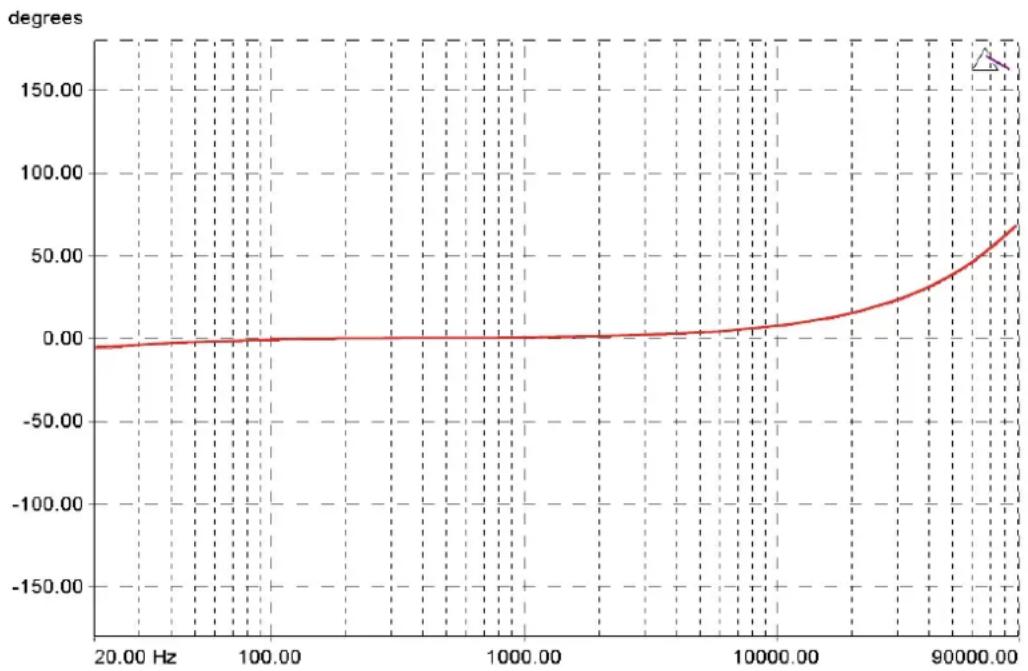
line
| Frequency (Hz) | degrees | | -------------- | ------- | | 20.00 | 0.00 | | 100.00 | 0.00 | | 1000.00 | 0.00 | | 10000.00 | 5.00 | | 90000.00 | 70.00 |This line shows the phase relationship between different frequencies in the signal sent through the X-Desk. SSL products are known for their “width” and “depth” in the mix, and much of this is down to the phase relationships between different parts of the signal. You can see that there is a fairly large “flat” section of phase response between 80Hz and 2kHz. When audio passes through the X-Phase, the phase of these frequencies remains largely unaffected by passing through the circuit. However, looking to the right hand side of the chart you can see that a frequency of 20kHz is 20^ out of phase with a frequency of 1kHz. This will affect how the frequencies in that signal interact by reinforcing and cancelling each other depending on their phase, which can lead to comb filtering.
You'd be amazed at some of the phase differences that happen when you run a signal through a device, with some particularly expensive devices having a +/-70^ degree phase difference between the low and the high frequencies; meaning that different parts of the audio signal could be 140^ out of phase with each other.
This is what X-Phase helps to solve; not only getting your signals in phase with each other, but also the frequencies within your signal to be in phase with themselves.
Here's the science...
THE ALL-PASS FILTER IDEA
An all-pass filter is a signal processing filter that passes all frequencies equally in gain, but changes the phase relationship between various frequencies. All frequency components of a signal are delayed when passed through a device such as an amplifier, a loudspeaker, or when propagating through space or a medium such as air. This signal delay will be different for the various frequencies unless the device has the property of being linear phase. (Linear phase and minimum phase are often confused – they are quite different.)
The delay variation means that signals consisting of multiple frequency components will suffer distortion because these components are not delayed by the same amount of time at the output of the device. This changes the shape of the signal, in addition to any constant delay or scale change. A sufficiently large delay variation can cause problems such as poor fidelity in audio or inter-symbol interference (ISI) in the demodulation of digital information from an analogue carrier signal.
X-Phase can solve these problems; for example, by aligning the overhead microphones of a drum-kit to the direct signals, while taking care of the fact that different frequencies need different delays.
Many people will be familiar with All-pass Filters as part of a loudspeaker processor, and this is a very good way to visualise them. Think about a two-way loudspeaker with a bass and high frequency driver. The acoustic centres of the two drivers are slightly different because of their physical placement. Even with the best crossover there are always frequencies that both drivers are reproducing at the same time. When the sound from each driver combines you will get 'comb filtering', or lobbing, as different wavelengths combine at different times. This will cause some frequencies to be completely cancelled, partly cancelled or combined to increase the level of others. These artefacts cannot be corrected using EQ filters. They can be used to partly mask the problem, but they won't solve it.
So how can we fix this problem? The answer is to use an all-pass filter. By setting the correct frequency and steepness we can correct the phase differences between the drivers, allowing them to sum together more accurately at the crossover point. The all-pass filter acts like a tilt control, shifting the phase of some frequencies relative to others.
So how does this relate to the creative mixing process, rather than for correcting loudspeakers?
If we now take the principle of the loudspeaker alignment example and apply it in the same way to instrument inputs, it will become clearer where the all-pass filter solves problems in a way no other audio processing can.
Imagine recording bass, a kick drum, a snare, a piano, or any instrument that will involve more than one microphone for recording. Most engineers will use a combination of polarity switching and/or delay to try and align the two sources so that they combine more smoothly. But let's take the snare top and bottom mics as an example.
In the same way that the high and low frequency drivers of the loudspeaker have some frequencies that overlap, so do the snare top and bottom mics.
Most engineers will try switching the polarity, thinking that negative pressure on the snare top mic will be reproduced as positive pressure on the bottom. On a very simple level this is true, but the phase will not be consistent across the whole frequency range, so comb filtering will occur. Switching polarity will just accentuate some frequencies and filter out others, it will not allow the frequencies that both microphones are picking up to combine correctly in time.
Bass DI and microphone channels suffer from a similar problem, but this time engineers tend to reach for the delay, thinking that the mic signal is behind the DI in time. This is true to some degree, but the bass speaker also has its own frequency dependent phase response, which a delay can't fix because it affects all frequencies. Both these examples use a tool to try and fix a problem, but neither delay or polarity are the right tool. They are like a sledgehammer.
What we need is a more accurate and delicate tool, and this is where the all-pass filter comes in. This is more like a precision tool, like a scalpel. Lets take a different example; an acoustic piano. If you use three microphones for a piano they are all separated by different physical distances and are all picking up similar frequencies. But when you try and mix those three microphones together you will have a similar comb filtering effect to the loudspeaker once again. This will affect your tone and your gain before feedback. Once again, delay, polarity or EQ can't fix this problem, they can only mask it to some degree.
Using an all-pass filter, we can adjust the phase response of each mic input so that they combine together more coherently. This gives us a more natural overall tone from the piano and much higher gain before feedback as both the phase and frequency response is smoother. The all-pass filter is a tool like no other in a sound engineer's tool kit.
11. FlexVerb
INTRODUCTION
The illustration below gives an overview of the FlexVerb features which are described in full over the following pages.
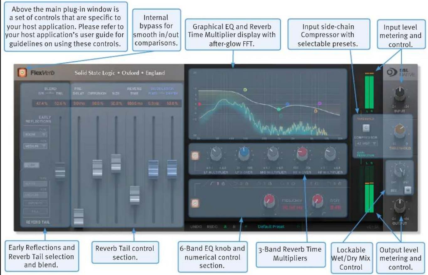
text_image
Above the main plug-in window is a set of controls that are specific to your host application. Please refer to your host application's user guide for guidelines on using these controls. Internal bypass for smooth in/out comparisons. Graphical EQ and Reverb Time Multiplier display with after-glow FFT. Input side-chain Compressor with selectable presets. Input level metering and control. FlexVerb Solid State Logic • Oxford • England BLEND PRO STR TAIL PREI DELAY DIFFUSION SIZE REVENUE MODULAR/BOX FREQ —— DEPTH 47.4% 52.6% 30 ms 50.0% 32.9% $800 ms 6.3 Hz 50.0% EARLY REFLECTIONS ROOM MEDIUM REVERB TAIL Early Reflections and Reverb Tail selection and blend. Reverb Tail control section. 6-Band EQ knob and numerical control section. 3-Band Reverb Time Multipliers Lockable Wet/Dry Mix Control Output level metering and control.INTERFACE OVERVIEW
The basic interface techniques for the FlexVerb are largely identical to those for the Channel Strip.
Automation
Automation support for FlexVerb is the same as for the Channel Strip.
Plug-in Bypass

The In/Out switch located above the Input section provides a plug-in bypass. This allows for smooth In/Out comparisons by triggering the host application's Bypass function. The button must be 'lit' for the plug-in to be in circuit.
Presets
Factory presets are included in the plug-in installation, installed in the following locations:
Mac:
ibrany/Application Support/Solid State Logic/SSLNative/Presets/FlexVerb
Windows 64-bit:
C:\ProgramData\Solid State Logic\SSL Native\Presets\FlexVerb

Switching between presets can be achieved by clicking the left/right arrows in the preset management section of the plug-in GUI, and by clicking on the preset name which will open the preset management display.
Preset Management Display
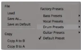
text_image
File Load Save As... Save as Default Copy Copy A to B Copy B to A Factory Presets Bass Presets Vocal Presets Drum Presets Guitar Presets Default PresetThere are a number of options in the Preset Management Display:
- Load allows loading of presets not stored in the locations described above.
- Save As... allows for storage of user presets.
- Save as Default assigns the current plug-in settings to the Default Preset.
- Copy A to B and Copy B to A assigns the plug-in settings of one comparison setting to the other.
A-B Comparisons

The A B buttons at the base of the screen allows you to load two independent settings and compare them quickly. When the plug-in is opened, setting A is selected by default. Clicking the A or B button will switch between setting A and setting B.
UNDO and REDO functions allow undo and redo of changes made to the plug-in parameters.
Input and Output Levels
The input and output sections provide input and output gain control, and input/output metering. When clipping occurs, the meter will turn red. It will remain red until the meter is reset by clicking on the meter.
FlexVerb Signal Flow
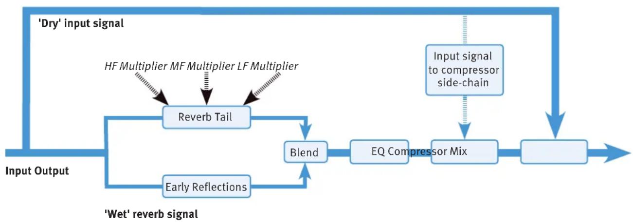
flowchart
graph TD
    A["Input Output"] --> B["Reverb Tail"]
    B --> C["Blend"]
    C --> D["EQ Compressor Mix"]
    D --> E["Output"]
    F["'Dry' input signal"] --> B
    G["'Wet' reverb signal"] --> H["Early Reflections"]
    H --> C
    I["Input signal to compressor side-chain"] --> D
    J["HF Multiplier MF Multiplier LF Multiplier"] -.-> B
Early Reflections and Reverb Tail Selection
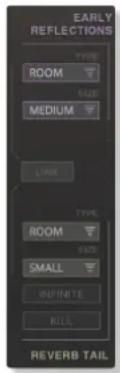
text_image
EARLY REFLECTIONS TYPE ROOM SIZE MEDIUM LINK TYPE ROOM SIZE SMALL INFINITE KILL REVERB TAILThere are four reverb types: Room, Hall, Plate and Chamber. Each reverb type has three sizes: Small, Medium, and Large.
Select the Early Reflection and Reverb Tail type and size by clicking on the drop-down selection boxes.
With the LINK engaged, selecting the Early Reflection Type and Size will allocate the same settings for the Reverb Tail. With the LINK disengaged, the Reverb Tail Type and Size is independent of the Early Reflections.
The INFINITE switch sets an infinite reverb time value, the KILL switch kills the reverb tail.
Reverb Tail Control Section
This section describes the functionality of the control faders for adjusting the reverb tail settings.
| Parameter Description | |
| Blend ER & Tail The mix between the early reflections and the reverb tail. | |
| Pre-Delay The delay between the input signal and the reverb. | |
| Diffusion Adjusts the focus and definition in the reflections. | |
| Size Emulates the size of a space, altering the quantity and speed of the reflections. | |
| Reverb Time The length of the reverb tail. | |
| Modulation Rate & Depth Applies light frequency modulation to the reverb, giving a more natural sounding reverb tail. | |
3-Band Reverb Time Multipliers
The reverb tail is split into three frequency bands with adjustable crossover points. Each of these frequency bands has an adjustable reverb time; the multipliers increase or decrease the reverb time parameter in the Reverb Tail control section (detailed above) for each frequency band. This is a useful way to shape the tonal quality of the reverb, and gives a more natural sound than using EQ.

text_image
LF MULTIPLIER 20 500 x 0.1 x 4.0 LF X-OVER MID MULTIPLIER 600 20k HF X-OVER x 0.1 x 4.0 HF MULTIPLIER6-Band EQ
Six bands of EQ can be applied to the reverb tail to shape overall reverb tone. This includes two parametric bands, high-shelf and low shelf bands, as well as high-pass and low-pass filters. The EQ only affects the reverb; it does not affect the input source signal.

text_image
1 2 3 4 5 6 FREQUENCY 20.00 Hz R/OFF 0dBInput Side-Chain Compressor
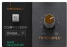
text_image
THRESHOLD COMPRESSOR STANDARD.. GAIN REDUCTION +10 30 THRESHOLDA compressor is applied to the output of the reverb with nine presets (fixed attack, release, and ratio settings), and adjustable threshold control. The compressor's side-chain is fed by the dry input signal.
This is useful, for example, to sit a larger-than-life vocal reverb in a busy mix; when there are vocals in the track, the accompanying reverb is automatically reduced in volume until the vocals stop, allowing the reverb to increase in level, giving the impression of a larger-than-life reverb without masking the intelligibility of the vocals.
Graphical Display
The graphical display shows:
- The resultant curve of the EQ section that can be adjusted from the draggable circular nodes.
- The reverb time multiplier crossover points and values that can be adjusted from the draggable square nodes.
• An FFT analysis with after-glow.
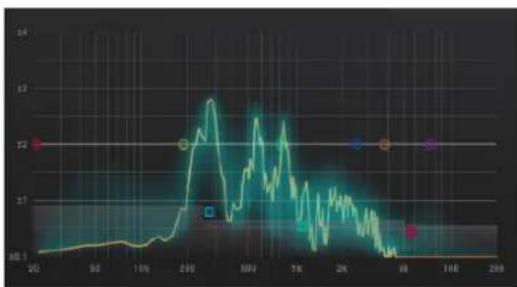
line
| Time | Value | |------|-------| | 20 | 60 | | 30 | 65 | | 100 | 70 | | 200 | 12 | | 300 | 13 | | 500 | 11 | | 1K | 9 | | 2K | 7 | | 10K | 6 | | 16K | 5 | | 280 | 4 |The FFT can be switched off by right/CTRL-clicking the graphical display, and selecting 'off'.
Mix
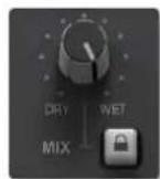
A Dry/Wet control for applying reverb directly to channel processing, rather than via an aux send.
The lock function excludes the mix control parameter from the preset management system.
The lock function is useful, for example, when switching between multiple presets; set the mix control to the preferred blend of 'Dry' input signal and 'Wet' reverb signal, then audition different reverb presets without affecting the mix.
Solid State Logic
OXFORD·ENGLAND
Visit SSL at: www.solidstatelogic.com
82BDNM01E
© Solid State Logic
All rights reserved under International and Pan-American Copyright Conventions
SSL® and Solid State Logic® are ® registered trademarks of Solid State Logic. SSL Native™ is a trademark of Solid State Logic.
All other product names and trademarks are the property of their respective owners and are hereby acknowledged.
No part of this publication may be reproduced in any form or by any means, whether mechanical or electronic, without the written permission of Solid State Logic, Oxford, OX5 1RU, England
As research and development is a continual process, Solid State Logic reserves the right to change the features and specifications described herein without notice or obligation.
Solid State Logic cannot be held responsible for any loss or damage arising directly or indirectly from any error or omission in this manual.
E&OE