EXO1 ProDSS - Environmental sensor YSI - Free user manual and instructions
Find the device manual for free EXO1 ProDSS YSI in PDF.

User questions about EXO1 ProDSS YSI
0 question about this device. Answer the ones you know or ask your own.
Ask a new question about this device
Download the instructions for your Environmental sensor in PDF format for free! Find your manual EXO1 ProDSS - YSI and take your electronic device back in hand. On this page are published all the documents necessary for the use of your device. EXO1 ProDSS by YSI.
USER MANUAL EXO1 ProDSS YSI
Environmental Solutions
natural_image
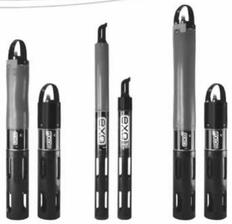
Five black cylindrical oil pumps with visible branding and no text or symbols on the pump bodyUSER MANUAL
ITEM# 603789REF
REVISION L
EXO User Manual

It's your world. Protect it.
The information contained in this manual is subject to change without notice.
Effort has been made to make the information in this manual complete, accurate, and current.
The manufacturer shall not be held responsible for errors or omissions in this manual.
Consult YSI.com/EXO for the most up-to-date version of this manual.
THIS IS AN INTERACTIVE DOCUMENT
When viewing this document as an Adobe™ PDF, hovering your cursor over certain phrases will bring up the finger-point icon. Clicking elements of the Table of Contents, website URLs, or references to certain sections will take you automatically to those locations.

Product Components
Carefully unpack the instrument and accessories and inspect for damage. If any parts or materials are damaged, contact YSI
Customer Service at 800-897-4151 (+1 937 767-7241) or the authorized YSI distributor from whom the instrument was purchased.
Technical Support
Telephone: 800 897 4151 (USA), +1 937 767 7241 (Globally)
Monday through Friday, 8:00 AM to 5:00 ET
Fax: +1 937 767 9353 (orders)
Email: info@ysi.com
YSI.com

EXO University
Watch our on-demand training videos for all things EXO!
YSI.com/EXO-University
TABLE OF CONTENTS
1. EXO Platform Overview
1.1 EXO1 Sonde Overview
1.2 EXO1 ^5 Sonde Overview
1.3 EXO2 Sonde Overview
1.4 EXO2 Sonde Overview
1.5 EXO3 Sonde Overview
1.6 EXO3 ^5 Sonde Overview
1.7 EXO Field Cables Overview
1.8 EXO Handheld Overview
1.9 EXO GO Overview
2. Operation
2.1 Sonde Install / Replace EXO1 Batteries
2.2 Sonde Install / Replace EXO2 and EXO3 Batteries
2.3 Install / Remove Guard or Cal. Cup
2.4 Install / Remove Sensors
2.5 Sonde States and LED Descriptions
2.6 Connection Methods Overview
2.7 Awaken Sonde, Activate Bluetooth
2.8 Connect Sonde, Bluetooth
2.9 Connect Sonde, SDI-12 - EXO3 Only
2.10 Communication Adapters Overview
2.11 Communication Adapters, USB
2.12 Communication Adapters, DCP
2.13 Communication Adapter, R5-232
2.14 Communication Adapters, SDI-12
2.15 Communication Adapters, Modbus
2.16 Connect Sonde, Flow Cell
2.17 Daisy Chaining, Sonde Expansion
2.18 Sonde Clamping / Mooring, Long-Term Monitoring
3. Kor Software
3.1 Introduction
3.2 Installation
3.3 Instrument Connection Panel
3.4 Home Screen
5. Sensors and Calibration
5.1 Sensors Overview
5.2 Calibration Basic Overview
5.3 Calibration Report
5.4 SmartQC Overview
5.5 Conductivity / Temperature Sensor Overview
5.6 Conductivity / Temperature Calibration
5.7 Wiped Conductivity / Temperature Sensor Overview
5.8 Wiped C/T Calibration and Deployment
5.9 Depth and Level Sensor Overview
5.10 Depth and Level Calibration
5.11 Dissolved Oxygen Sensor Overview
5.12 Dissolved Oxygen Calibration
5.13 fDOM Sensor Overview
5.14 fDOM Calibration Standards
5.15 fDOM Calibration
5.16 ISEs: Ammonium, Nitrate, & Chloride Overview
5.17 ISEs: Ammonium, Nitrate, & Chloride Calibration
5.18 NitraLED UV Nitrate Overview
5.19 NitraLED Calibration and Correction
5.20 pH and ORP Sensor Overview
5.21 pH Calibration
5.22 ORP Calibration
5.23 Rhodamine Sensor Overview
5.24 Rhodamine Calibration
5.25 Total Algae Sensor Overview
5.26 Total Algae Calibration
5.27 Turbidity Sensor Overview
5.28 Turbidity Calibration
5.29 Total Suspended Solids Calculation


6. Maintenance
6.1 Sonde Storage
6.2 Sonde Maintenance
6.3 Replace EXO1 Sonde Bail
6.4 Replace EXO2 & EXO3 Sonde Bail
6.5 Depth and Level Sensor Maintenance and Storage
6.6 Standard Optical Sensor Maintenance and Storage
6.7 C/T Sensor Maintenance and Storage
6.8 Dissolved Oxygen Sensor Storage
6.9 Dissolved Oxygen Sensor Maintenance and Rehydration
6.10 Dissolved Oxygen Sensor Cap Replacement
6.11 pH and pH/ORP Sensor Storage and Rehydration
6.12 pH and pH/ORP Sensor Maintenance
6.13 ISE Maintenance and Storage
6.14 Sensor Module Replacement
6.15 EXO Central Wiper Maintenance and Storage
6.16 EXO Field Cable Maintenance and Storage
6.17 Connectors Maintenance and Storage
6.18 Anti-fouling Equipment Maintenance
6.19 Flow Cell Maintenance
6.20 Storage Cases, Packing Options
7. EXO Handheld
7.1 EXO Handheld General Operation
7.2 Handheld Menu
7.3 Deploy Menu
7.4 Calibration Menu
7.5 Data Menu
8. Vented Level Sonde
8.1 Vented Level Sonde Overview
8.2 Vented Level Sonde Installation
8.3 Vented Cables and Desiccants Installation
8.4 Calibration
8.5 Maintenance and Storage
9. EXO PAR
9.1 EXO PAR Introduction
A FVO BAN 10-11

natural_image
Technical illustration of a handheld device with multiple cylindrical components and a handle (no visible text or symbols)
natural_image
Close-up of a black exo-branded industrial device with coiled cables and control panel (no visible text or symbols)
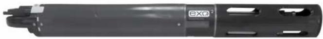
EXO1 Sonde
Overview
The EXO1 sonde is a multiparameter instrument that collects water quality data. The sonde collects the data with up to four user-replaceable sensors and an optional integral pressure transducer. Each sensor measures its parameter via a variety of electrochemical, optical, or physical detection methods. Each port accepts any EXO sensor and automatically recognizes its type. The EXO1 has an internal battery compartment and can be powered either by D-cell batteries, external 9-16 volt DC, or using external power with internal battery backup. Depending upon user-defined settings, the EXO1 will collect data and store it onboard the sonde, transfer the data to a data collection platform (DCP), or relay data directly to a user's PC, mobile device, or the EXO Handhold. See Section 8 for information specific to vented level sondes.
Users communicate with the sonde via a field cable to an EXO Handheld, Bluetooth* wireless connection to a PC or EXO Classic. Handheld, or a USB connection (via communications adapter) to a PC.
Specifications
| Operating EnvironmentDepth Rating | 250 meters, 820 feet |
| Material | Xenoy ^ , Lexan ^ , titanium,316 stainless steel |
| Internal Logging Memory Capacity | 512 MB |
| Software Kor Software | |
| Application Kor Mobile for Android | |
| Communications Sonde | Wireless: BluetoothField Cable: RS-485 |
| Adapters | RS-232, Modbus,USB, SDI-12 |

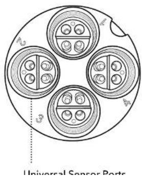
EXO1 Bulkhead
text_image
Universal Sensor Ports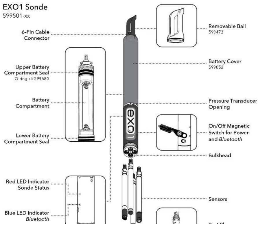
text_image
EXO1 Sonde 599501-xx 6-Pin Cable Connector Upper Battery Compartment Seal O-ring kit 599680 Battery Compartment Lower Battery Compartment Seal Removable Bail 599473 Battery Cover 599052 Pressure Transducer Opening On/Off Magnetic Switch for Power and Bluetooth Bulkhead Red LED Indicator Sonde Status Blue LED Indicator Bluetooth Sensors
EXO1 ^s Sonde
Overview
The EXO1 ^2 sonde is compact, batteryless version of the EXO1 sonde for use where external power is available. The sonde collects data with up to four user-replaceable sensors and an integral pressure transducer. The EXO1 ^2 features the same logging and communication options as the standard EXO1; however, an external power source is required. Power can be supplied via a DCP, the EXO Handheld or EXO GO. See Section 2.6 for a communication overview.
Specifications
| Operating EnvironmentDepth Rating | 250 meters, 820 feet* |
| Material | Xenoy®, Lexan®, titanium,316 stainless steel |
| Internal Logging Memory Capacity | 512 MB |
| Software Kor Software | |
| Application Kor Mobile for Android | |
| Communications SondoAdapters | Wireless: BluetoothField Cable: RS-485RS-232, Modbus,USB, SDI-12 |
| Power External 9-16 VDC | |
| Temperature Operating | 5 to +50°C |

EXO1 ^s Bulkhead

natural_image
Diagram of four circular components with internal circular elements, arranged in a ring (no text or symbols)Universal Sensor Ports

text_image
EXO1s Sonde 577501-xx 6-Pin Cable Connector Removable Bail 599473 Red LED Indicator Sonde Status On/Off Magnetic Switch for Power and Bluetooth Bulkhead Blue LED Indicator Bluetooth Sensors Port Plug 599475 Sensor Guard 599666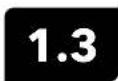
EXO2 Sonde
Overview
The EXO2 sonde is a multiparameter instrument that collects water quality data. The sonde collects the data with up to seven user-replaceable sensors and an integral pressure transducer. Each sensor measures its parameter via a variety of electrochemical, optical, or physical detection methods. Each port accepts any EXO sensor and automatically recognizes the type of sensor. The EXO2 has an internal battery compartment and can be powered either by D-cell batteries, external 9-16 volt DC, or using external power with internal battery backup. Depending on user-defined settings, the EXO2 will collect data and store it onboard the sonde, transfer the data to a data collection platform (DCP), or relay it to a user's PC, mobile device, or EXO Handheld via cable, USB connection, or Bluetooth* connection.
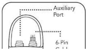
In addition to six standard sensor ports, the central port (port 7) can accept either a Central Wiper or an additional sensor. The auxiliary port on top of the sonde will allow the user to connect the EXO2 to other EXO sondes, making this our most expandable and flexible sonde. See Section 8 for information specific to vented level sondes.
Users communicate with the sonde via a field cable to an EXO Handheld, Bluetooth wireless connection to a PC or EXO Classic Handheld, or a USB connection (via communications adapter) to a PC. See Section 2.6 for a communication overview.
Specifications
| Operating EnvironmentDepth Rating | 250 meters, 820 feet |
| Material | Xenoy , Loxan , titanium,316 stainless steel |
| Internal Logging Memory Capacity | 512 MB |
| Software Kor Software | |
| Application Kor Mobile for Android | |
| Communications Sonde | Wireless: Bluetooth |

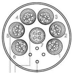
EXO2 Bulkhead

text_image
4 3 5 2 7 6 1
text_image
EXO2 Sonde 599502-xx Auxiliary Port 6-Pin Cable Connector Battery Compartment Opening Battery Cap/ Pressure Relief Valve O-ring kit 599681 REMOVABLE Bail 599474 Battery Compartment On/Off Magnetic Switch for Power and Bluetooth Pressure Transducer Opening Bulkhead Sensors Red LED Indicator Sonde Status Blue LED Indicator Bluetooth Port Plug 599475
EXO2 ^s Sonde
Overview
The EXO2 ^5 sonde is compact, battery-less version of the EXO2 sonde for use where external power is available. The sonde supports up to seven user-replaceable sensors and an integral pressure transducer. The EXO2 features the same logging and communication options as the standard EXO2; however, an external power source is required. Power can be supplied via a DCP, the EXO handheld or EXO GO. See Section 2.6 for a communication overview.
In addition to six standard sensor ports, the central port (port 7) can accept either a Central Wiper or an additional sensor. The auxiliary port on top of the sonde will allow the user to connect the EXO2 ^c to other EXO sondes, making this our most expandable and flexible sonde.
Specifications
| Operating EnvironmentDepth Rating | 250 meters, 820 feet |
| Material | Xenoy*, Lexan*, titanium,316 stainless steel |
| Internal Logging Memory Capacity | 512 MB |
| Software Kor Software | |
| Application Kor Mobile for Android | |
| Communications Sonde | Wireless: BluetoothField Cable: RS 485 |
| Adapters | RS-232, Modbus. |
EXO2 ^s Bulkhead
text_image
4 3 2 5 7 6 1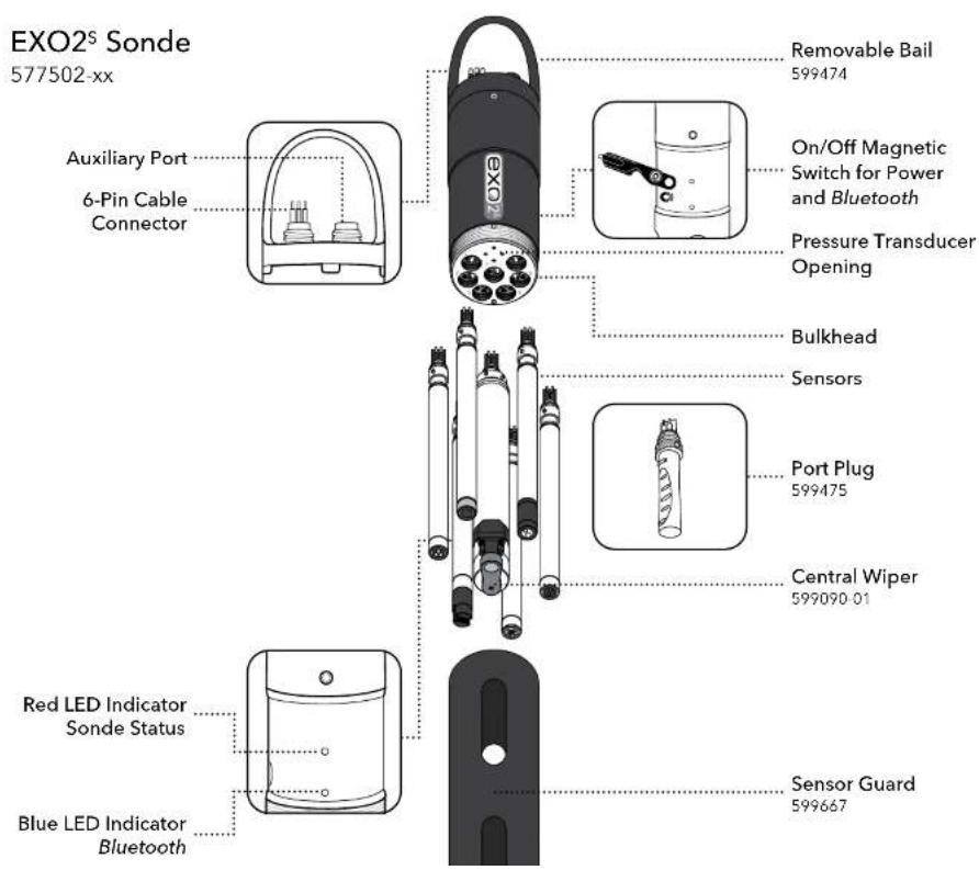
text_image
EXO2® Sonde 577502-xx Auxiliary Port 6-Pin Cable Connector Removable Bail 599474 On/Off Magnetic Switch for Power and Bluetooth Pressure Transducer Opening Bulkhead Sensors Port Plug 599475 Central Wiper 599090-01 Red LED Indicator Sonde Status Blue LED Indicator Bluetooth Sensor Guard 599667
EXO3 Sonde
Overview
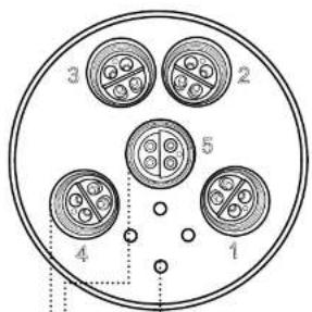
The EXO3 sonde is a multiparameter instrument that collects water quality data. The sonde collects the data with up to five user-replaceable sensors and an integral pressure transducer. The EXO3 has a central port for an EXO wiper (or asensor). Each sensor measures its parameter via a variety of electrochemical, optical, or physical detection methods. Each port accepts any EXO sensor and automatically recognizes the type of sensor. The EXO3 has an internal battery compartment and can be powered either by D-cell batteries, external 9-16 volt DC, or using external power with internal battery backup. Depending on user-defined settings, the EXO3 will collect data and store it onboard the sonde, transfer the data to a data collection platform (DCP), or relay it to a user's PC, mobile device, or EXO Handheld via cable, USB connection, or Bluetooth connection.
Users communicate with the sonde via a field cable to an EXO Handheld, Bluetooth wireless connection to a PC or mobile device, or a USB connection (via communications adapter) to a PC. See Section 2.6 for a communication overview.
NOTE: The EXO3 Sondo includes integral SDI-12 communications for use with cables up to 100 motors in length. With EXO3, a 599820 Signal Output Adapter (SOA) is not necessarily required. See Section 2.9 for details.
Specifications
| Operating EnvironmentDepth Rating | 250 meters, 820 feet |
| Material | Xenoy ^a , Lexan ^b , titanium,316 stainless steel |
| Internal Logging Memory Capacity | 512 MB |
| Software Kor Software | |
| Application Kor Mobile for Android | |
| Communications Sonde | Wireless: BluetoothField Cable: RS-485, SDI-12 |
| Adapters | RS-232, Modbus, |
EXO3 Bulkhead
text_image
3 2 5 4 1
text_image
EXO3 Sonde 599503-xx 6-Pin Cable Connector Battery Compartment Opening Battery Cap/ Pressure Relief Valve O-ring kit 599681 Removable Bail 599474 Battery Compartment On/Off Magnetic Switch for Power and Bluetooth Pressure Transducer Opening Bulkhead Sensors Port Plug 599475 Central Wiper 599090-01 Red LED Indicator Sonde Status Blue LED Indicator Bluetooth
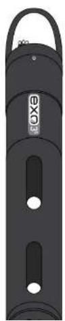
EXO3 ^s Sonde
Overview
The EXO3 sonde is compact, battery-less version of the EXO3 sonde for use where external power is available. The sonde collects the data with up to five user-replaceable sensors and an integral pressure transducer. The EXO3 has a central port for an EXO wiper (or a sensor). The EXO3 features the same logging and communication options as the standard EXO3; however, an external power source is required. Power can be supplied via a DCP, the EXO Handheld or EXO GO. See Section 2.6 for a communication overview.
NOTE: The EXO3 ^® Sonde includes integral SDI-12 communications for use with cables up to 100 meters in length. With EXO3 ^® , a 599820 Signal Output Adapter (SOA) is not necessarily required. See Section 2.9 for details.
Specifications
| Operating EnvironmentDepth Rating | 250 meters, 820 feet |
| Material | Xenoy ^3 , Lexan ^5 , titanium, 316 stainless steel |
| Internal Logging Memory Capacity | 512 MB |
| Software Kor Software | |
| Application Kor Mobile for Android | |
| Communications Sonde | Wireless: BluetoothField Cable: RS-485, SDI-12 |
| Adapters | RS-232, Modbus, USB, SDI-12 |
| Power External 9-16 VDC | |
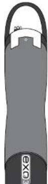
natural_image
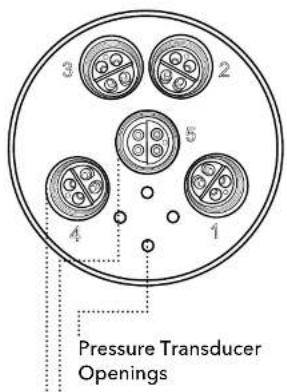
Black cylindrical device with two side slots and a handle, no visible text or symbolsEXO3 ^s Bulkhead
text_image
Pressure Transducer Openings
text_image
EXO3® Sonde 577503-xx 6-Pin Cable Connector Removable Bail 599474 On/Off Magnetic Switch for Power and Bluetooth Pressure Transducer Opening Bulkhead Sensors Port Plug 599475 Central Wiper 599090-01 Red LED Indicator Sonde Status Blue LED Indicator Bluetooth Sensor Guard 599667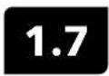
EXO Field Cables
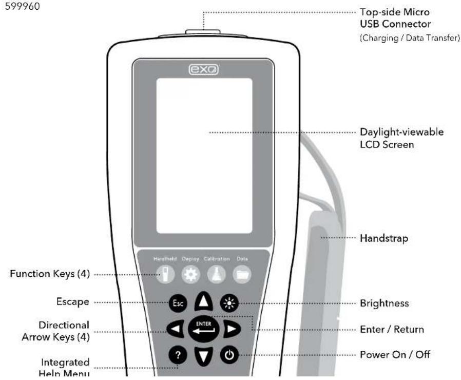
Overview
The EXO rugged field cable comes in many different lengths and options to meet the needs of your specific application. Selecting the correct cable length and coupler will ensure the best quality data for your project. For a full list of cable options and precautions for extended cables, please see Cable Options on the following page.
text_image
Male (black) wet-mate connector Connects to Handheld or EXO GO Female (white) wet-mate connector Connects to Sande Cable Grip KitCable Options
| 599431-01 EXO Cable Coupler, Titanium | 599040-250 EXO 250 meter Field Cable |
| 599431-02 EXO Cable Coupler, Brass | 599040-300 EXO 300 meter Field Cable |
| 599040-2 EXO 2 meter Field Cable | 599008-10 EXO 10 meter Flying Lead Cable |
| 599040-4 EXO 4 meter Field Cable | 599008-15 EXO 15 meter Flying Lead Cable |
| 599040-10 EXO 10 meter Field Cable | 599008-33 EXO 33 meter Flying Lead Cable |
| 599040-15 EXO 15 meter Field Cable | 599008-66 EXO 66 meter Flying Lead Cable |
| 599040-33 EXO 33 meter Field Cable | 599008-100 EXO 100 meter Flying Lead Cable |
| 599040-66 EXO 66 meter Field Cable | 599210-4 EXO 4 meter VENTED Flying Lead Cable |
| 599040-100 EXO 100 meter Field Cable | 599210-10 EXO 10 meter VENTED Flying Lead Cable |
| 599040-150 EXO 150 meter Field Cable | 599210-15 EXO 15 meter VENTED Flying Lead Cable |
| 599040-200 EXO 200 meter Field Cable | 599210-33 EXO 33 meter VENTED Flying Lead Cable |
Extended Field Cables Precaution
There are some limitations for applications using EXO cable lengths greater than 100 meters - whether by extended cables, or by means of cable-coupling.
NOTICE: To prevent system problems related to power and signal integrity, make sure you understand the system limitations if you plan to use cable couplers or extended cables.
Voltage drop through long cables can adversely affect the available power at the sonde.

EXO Handheld
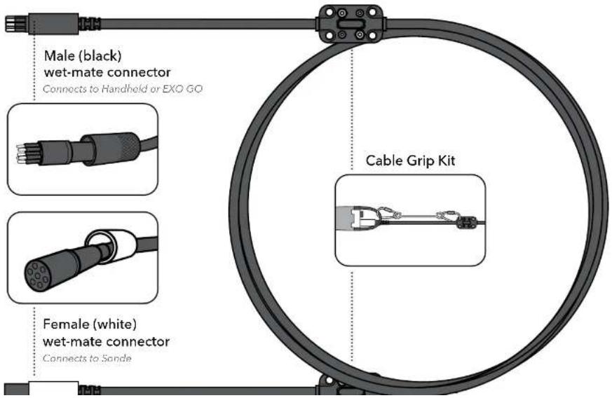
Overview
The EXO Handheld is a rugged, microcomputer-based instrument that allows the user to display sonde readings, configure sondes, store and retrieve data, and transfer data from sondes to a computer. Equipped with GPS and an integrated barometer, the Handheld communicates via field cable or USB connector.
The unit also utilizes an adjustable backlit screen for easy day or night viewing. The handheld features a built-in rechargeable Lithium-Ion battery, integrated help menus, a simplified user interface, and an ergonomic design.
NOTE: For operating instructions, please see Section 7.
Specifications
| GPSAccuracy | Yes2.5 m CEP(dependent on site conditions) |
| Display | IP-67 rated, Color-LCD graphic display |
| Memory >100,000 data | sets |
| Software Kor Software | |
| Communications Field | Cable, USB |
| PowerInternal | RechargeableLithium-Ion Pack |
| Operating TimeCharging Time | >15 hours9 hours (from 0 to 100%) |
| TemperatureOperating | 0°C to 50°C |
| Storage | 20°C to 30°C (with 1 hour) |
EXO Handheld

text_image
Top View GPS Antenna (Internal) Micro US B Port (Charging / Data Transfer) Handstrap Mount (2) Back ViewEXO Handheld
text_image
599960 Top-side Micro USB Connector (Charging / Data Transfer) EXO Daylight-viewable LCD Screen Handstrap Function Keys (4) Escape Directional Arrow Keys (4) Integrated Help Menu Handheld Deploy Calibration Data Enter / Return Power On / Off Brightness
EXO GO
Overview
EXO GO is a compact, rugged device that enables Bluetooth ^® communication between a submerged EXO sonde and a device running Kor Software. EXO GO remains topside while connected to a sonde via the field cable. Pair with a tablet, smartphone, or laptop running Kor to form a complete sampling system.
With an integral barometer and GPS, EXO GO provides barometric pressure and location data in addition to the connected sonde data. The built-in, rechargeable Lithium-Ion battery will power an EXO Sonde for a full day of sampling. EXO GO must be charged via the micro USB port before first use. LED indicators represent battery level, charge status, and Bluetooth status, as shown in the diagram below.
NOTE: Update to the latest versions of Kor Software and Kor Mobile to use EXO GO.
Specifications
| Communications Bluetooth, USB 2.0 | |
| Software Kor Software | |
| Application Kor Mobile for Android | |
| Bluetooth Range | Class 210 m |
| Barometer Range Accuracy Resolution | Built-in with Usor Calibration375 to 825 mmHg±1.5 mmHg0.1 mmHg |
| GPS Accuracy 2.5 m CEP | (dependent on site conditions) |
| Battery Operating Time Charge Time | Rechargeable Lithium-Ion>15 hours (powering full EXO3)9 hours (from 0 to 100%) |
LED Descriptions

text_image
BLUE LED - Bluetooth status Solid: On, not linked Blinking: On, linked COMM BATTERY GREEN LED - 100 to 50% charge YELLOW LED - 50 to 25% charge RED LED - less than 25% chargeEXO GO
577400

text_image
Wet-Mate Connector Bail exo™ GO Monitoring Made Mobile Barometer Back Power Button
natural_image
Two workers in life vests and safety gear inspecting a small boat with a gun, near a water body (no visible text or symbols)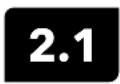
Sonde
Install / Replace EXO1 Batteries
EXO1 water quality sondes use two (2) D-cell batteries as a power source. Using alkaline batteries, users can expect approximately 90 days of deployment from a fully loaded sonde that samples once every 15 minutes. However, deployment times may vary greatly depending on water temperature, sampling rate, sensor payload, and brand of battery.
See Battery Life Specification on the next page.
NOTICE: Do not use Ni-Cad or 3.6 V Lithium batteries in the EXO1 sonde.

natural_image
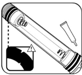
Diagram of a mechanical tool with directional arrows and a separate close-up view (no text or symbols)1 Remove battery cover
Start with a clean and dry sonde. Hold the sonde horizontally with the bail up and twist the battery cover counterclockwise until free. If necessary, slide the sonde tool's larger opening over the end of the battery compartment and use it as a lever to break the compartment free. Then slide off the battery cover.
NOTICE:
Do not remove the screws on the sonde.
Do not clamp the sonde in a vise.

natural_image
Diagram of a pen-like object with internal bands and arrows indicating movement or force (no text or symbols)2 Remove old batteries
Expose the batteries by flipping the isolation flap up away from the batteries, and pull the batteries free of their compartment. Always dispose of used alkaline batteries according to local requirements and regulations.
Clean the inside of the battery compartment with a lint-free cloth.
text_image
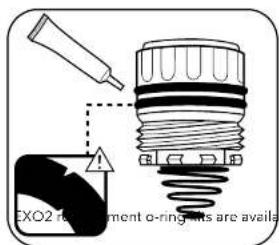
Diagram of a pen with warning symbol and magnified detail showing internal components4 Check and service o-rings
NOTE: Before replacing the battery cover, check and service the four o-rings.
Ensure that the o-rings are not nicked or torn and that there are no contaminants or particles on them or the sealing surfaces inside the battery cover. Clean the o-rings with a lint-free cloth. Then apply a thin coat of silicone grease to each o-ring, using a finger to feel for damage. Replace any damaged o-rings.
EXO1 replacement o-ring kits are available, part #599680.

natural_image
Diagram of a pen-like tool with directional arrows indicating movement or force (no text or symbols)5 Replace battery cover
Slide the battery cover over the sonde, making sure the rubber battery flaps are tucked under the edge of the cover to prevent it from tearing the flaps. Twist the battery cover clockwise until it stops at the rubber gasket. The gasket does not provide a seal and does not need to be compressed.
NOTICE: Do not overtighten; overtightening will not create a strong seal and may damage the sonde.
The EXO1 sonde has a resealing pressure relief valve; no maintenance is required.
If a battery failure occurs that results in battery acid leakage into the battery compartment, the sonde must be returned to a service center for evaluation.
Battery Life Specification (Example)
When using alkaline batteries: Estimated battery life is approximately 90 days for
FVAT: 2016, 2P: 1, 1, 1, 1, 1, 1, 1, 1

Sonde
Install / Replace EXO2 and EXO3 Batteries
EXO2 sondes use four (4) D-cell batteries as a power source. Using alkaline batteries, users can expect approximately 90 days of deployment from a fully loaded sonde that samples once every 15 minutes. However, deployment times may vary greatly depending on water temperature, sampling rate, sensor payload, wiper frequency, and brand of battery. See Battery Life Specification on the next page.
EXO3 sondes use two (2) D-cell batteries as a power source and can expect 60 days of deployment with an average sensor payload while sampling once every 15 minutes.
NOTICE: Do not use Ni-Cad or 3.6 V Lithium batteries in the EXO sondes.
Pressure in Battery Compartment
The EXO2 and EXO3 sondes are equipped with a pressure relief valve to protect against catastrophic battery failure. If the valve is open (indicating an over-pressure situation), the battery cap must be replaced. Significant water leakage into the battery compartment requires that your instrument be evaluated by the manufacturer or Authorized Service Center before the next deployment.

WARNING: Do not paint over or cover the pressure release valve in any way.
Blocking the pressure release valve can lead to dangerously high internal pressure.

text_image
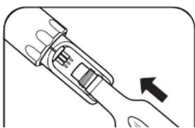
wrench EXO2 top1 Loosen battery cap
Start with a clean and dry sonde. Slide the sonde tool's smaller opening over the battery cap on top of the EXO2 or EXO3. Using the tool as a lever, firmly turn the tool counterclockwise until the battery cap is loose.
natural_image
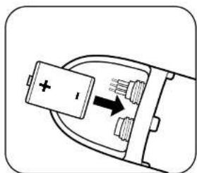
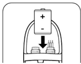
Diagram of a battery inside a socket with an arrow indicating direction (no text or symbols)3 Insert new batteries
With the positive terminal facing up, insert four (4) new D-cell batteries into the battery well for EXO2 sondes, or two (2) new D-cell batteries for EXO3 sondes. Tilt the sonde horizontally and gently slide the batteries into the sonde to avoid damaging the batteries or the battery terminal.
NOTICE:
Do not use Ni-Cad or 3.6 V Lithium batteries in the sondes. Damage to the circuit board is not covered under warranty.
text_image
EXO2 re-riment o-ring-its are availa4 Check and service o-rings
NOTE: Before replacing the battery cover, inspect and service the two o-rings.
Ensure that the o-rings are not nicked or torn and that there are no contaminants or particles on the o-rings or the sealing surfaces inside the battery cover. Then apply a thin coat of silicone grease to each o-ring, using a finger to feel for damage. Replace any damaged o-rings.
natural_image
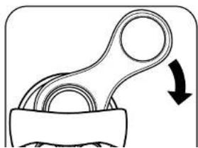
Diagram of a mechanical component with a curved arrow indicating rotation (no text or symbols)5 Replace battery cap
After servicing the cap's o-rings, insert the cap in its recess. Then, using your thumb, press down on the pressure relief valve while turning the cap clockwise. Once the cap threads are engaged, use the tool to tighten until snug.
NOTICE: Do not overtighten; overtightening will not create a stronger seal and may damage the sonde. When completed, the top o-ring of the cap must be below the battery compartment opening.
2.3 Install / Remove Guard or Cal Cup
Sensor guards protect EXO sensors from impact throughout deployment. Users must install the guard prior to data collection. The calibration cup (cal cup) is used for storage and calibration.
NOTE: We recommend using two sensor guards and two calibration cups: one for field deployments and a second used exclusively for calibrations. Using a second guard and calibration cup will minimize calibration solution contamination (especially for turbidity). EXO calibration cups install over an installed sensor guard. This configuration reduces the volume of standards required for calibration and protects the sensors during calibration.
natural_image
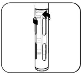
Diagram of a laboratory apparatus with a vertical tube and internal components, no visible text or symbols1 Install/remove sensor guard
Install guard by threading it onto the sonde bulkhead threads. Rotate the guard clockwise on the bulkhead to install, taking care not to pinch your fingers. Rotate it counterclockwise to remove. Always use one guard for deployment/storage and a second guard for calibration only.
Additional EXO sensor guards can be purchased:
EXO1 Guard Assembly Kit [part #599666]
EXO2/3 Guard Assembly Kit [part #599667]
NOTICE: Take care not to let the guard damage unguarded pH or pH/ORP sensors when installing and removing.
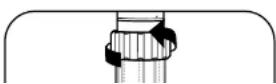
2 Install/remove calibration cup
Before installation, loosen (but do not remove) the cup's clamping ring. Then, with the sonde guard already installed, slide the cal cup over the guard until the
Install / Remove Sensors

EXO Sensor Installation Watch Now
EXO sensors have identical connectors and identify themselves via onboard firmware; therefore, users can install any probe into any universal sonde port. The exception is the wiper for the EXO2 and EXO3 sondes, which must be installed in the central port 7. Individual ports are physically identified by an engraved number on the sonde bulkhead. Although the probes are wet-mateable, users should clean, lubricate, and dry the sonde and sensor connectors prior to installation or service.
NOTE: The data displayed on the Handheld / Kor Software, or Kor Mobile, and the order of the exported data will be in the same order that the sensors are installed (e.g. a turbidity sensor in port 1 will display turbidity values first. The sensor in port 2, second, and so on).
natural_image
Technical illustration of a mechanical component with a directional arrow indicating motion (no text or symbols present)1 Remove probe or port plug
Remove the calibration cup and sensor guard from the sonde. Place the sonde on a clean, flat surface and prevent it from rolling.
If removing a sensor or port plug, use the probe tool in the locking nut and rotate counterclockwise to loosen. Pull the probe straight out of the port and place on a clean surface. Wipe dry with a clean, lint-free cloth.
natural_image
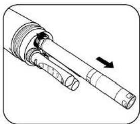
Mechanical assembly diagram showing a shaft and housing with an arrow indicating direction (no text or symbols)2 Clean port and install sensor
Visually inspect the port for contamination. If the port is dirty or wet, clean it with a clean, lint-free cloth or compressed air. Apply a light coat of silicone grease to the rubber mating surfaces of the connector (not the o-ring) and a small dab of silicone grease on the threads of the locking nut.
If the sensor is new or being taken out of storage remove any hydration caps or buffer bottles on the probe, insert the sensor into the part by properly aligning
2.5 Sonde Sates and LED Descriptions
States
An EXO sonde is always in one of three operational states: Off, Awake, or Asleep. These states determine the sonde's power usage and logging potential. When Off, the sonde is not powered (no batteries installed, no topside power) and cannot collect data. Users can apply power to the sonde internally, using batteries, or externally with an EXO field cable attached from the topside port to an EXO Handheld, DCP or other approved power source. Once power is applied to a sonde, it is either Awake or Asleep.
Power States
Off: Not powered, no data collection.
Asleep: Low power. Waiting for command.
Awake: Full power. Ready to collect.
LED Indicators
Blue LED-Bluetooth
None: Off, not active
On Solid: On, not linked
2 Hz (0.5 s Blink): On, linked
When Asleep, the sonde remains in a very low power setting and waits for a user command or its next scheduled logging interval. An Awake sonde is fully powered and ready to collect data. Once awakened, a sonde remains Awake for five minutes after its last communication via Bluetooth or 30 seconds after its last communication via the topside port. The sonde also automatically awakens 15 seconds before its next scheduled logging interval.
LED Indicators
Each sonde has two LED indicators that show the sonde's status. The blue LED indicates the Bluetooth's wireless connection status. The red LED indicates the sonde's power state.

The Bluetooth light (blue) is activated by a magnet swipe at the magnetic activation area. When the blue LED is off, the Bluetooth is disabled. When the light is on continuously, the Bluetooth is
enabled, but no link has been established. When the blue LED blinks at 2 Hz, the sonde's Bluetooth is on, and has established a link.
When the red LED is off, the sonde is either Off or Asloop and not logging. When it blinks at 0.1 Hz (once every 10 seconds), the sonde is Asleep and logging is enabled. When the red light blinks at 1 Hz, the sonde is Awake and has no faults. If the red light is lit continuously, the sonde is Awake and has detected faults that need to be fixed prior to
2.6
Connection Methods
Overview
Below is a high level overview of various methods you can use to connect and communicate with your EXO sonde:

natural_image
Illustration of a handheld medical or laboratory device with a bulb, cable, and connector (no text or symbols visible)Field Cable, Sonde-to-Handhelds
- Lab Calibration
• Transfer Data from Sonde
- Hardware Setup
- Field Sampling

text_image
Kor BluetoothWireless Bluetooth, Sonde-to-Computer or Mobile Device
- Lab Calibration
• Transfer & Export Data
- Hardware Setup
• External power required for EXO-S

flowchart
graph LR
    A["Laptop with 'Kor' icon"] <--> B["Bluetooth"]
    B --> C["Wireless device"]
EXO GO Bluetooth, Sonde-to-Computer or Mobile Device
- Lab Calibration
- Transfer & Export Data
- Hardware Setup
- Field Sampling
- Update Firmware

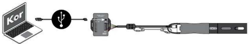
flowchart
graph LR
    A["Laptop with 'Kor' icon"] --> B["USB symbol"]
    B --> C["Connector"]
SOA-USB Adapter, Sonde-to-Computer
- Lab Calibration
• Transfer & Export Data
- Hardware Setup
- Field Sampling
- Update Firmware
2.7
Awaken Sonde
Activate Bluetooth
Once power is applied to the sonde, internally or externally, users can awaken their sondes from Sleep state using any of several methods. Primarily, users activate EXO sondes and the Bluetooth connections via a magnetic switch installed in the sonde's electronics compartment. The sonde will automatically disable the connection and go to sleep if it has received neither a Bluetooth signal for 5 minutes, nor a signal from the topside connector for 30 seconds. In order to activate their sondes, users should keep a magnet with them when setting up and deploying sondes. For more information on sonde states and LEDs, see Section 2.5.

text_image
magnet (inside tool)1 Awaken sonde with magnet
Users can make their sonde go to the Awake state by holding a magnet at the magnetic activation area on the sonde's bulkhead (identified by the illustrated magnet symbol on the label). Simply hold the magnet within one (1) cm of the symbol until the LEDs activate. EXO Classic Handhelds and sensor removal tools contain embedded magnets identified by the same symbol.

EXO Sensor Tool Kit [part #599469]
text_image
Diagram showing a battery with positive and negative terminals connected to a container with liquid and plug, indicating a process or setup.2 Awaken sonde without magnet
Users can also make their sonde go to the Awake state using any of the following methods.
- Cycling power to the sonde (uninstalling/installing batteries or disconnecting/reconnecting external power).
- Communicating via the topside port.
- Inserting a sensor.
In addition to these manual methods, the sonde also automatically awakens for
2.8
Connect Sonde
Bluetooth
Before users can communicate wirelessly with their EXO sondes, they must establish a Bluetooth link. All EXO sondes are equipped with Bluetooth. This technology provides a secure, two-way, reliable communication channel with which users can communicate with their sondes above water without cables. Many new computers are equipped with Bluetooth wireless installed internally; those without Bluetooth can use a Bluetooth dongle (not included). Follow the manufacturer's instructions for installing the dongle's software and hardware.

natural_image
Diagram showing a wall-mounted device connected to two rectangular panels with a lightbulb above (no text or symbols)1 Install Bluetooth dongle (optional)
If your computer is not equipped with internal Bluetooth radio, insert a Bluetooth dongle (not provided) into any of the computer's USB ports. Wait for the computer to automatically install the device and its drivers. Once the installation is complete, the computer should indicate that the device is installed and ready to use.

text_image
magnet (inside tool)2 Activate sonde's Bluetooth
Users activate Bluetooth wireless by holding a magnet at the magnetic activation area. In addition to magnetic activation, users can also activate Bluetooth by:
• Cycling power to the sonde (uninstalling/installing batteries).
- Enabling Bluetooth via a connection at the topside port using Kor.
Connect Sonde
SDI-12: EXO3 and EXO3 ^s Only
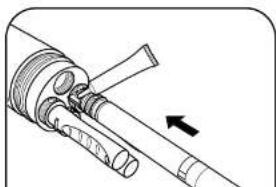
The EXO3 and EXO3 ^5 Sondes includes native SDI-12 output for use with flying lead cables for a direct interface into 3rd party DCP systems. A communication adapter is NOT required for EXO3 and EXO3 ^5 SDI-12 communication. Refer to the wiring diagram below for connecting the cable to a terminal:

flowchart
graph LR
    A["Ground"] --> B["Bare Wire"]
    B --> C["Orange Wire"]
    C --> D["Cable to EXO3 Water Quality Sonde"]
    E["Regulated 12VDC power supply (not included)"] --> F["1 AMP fast-blow fuse"]
    F --> G["Red Wire"]
    G --> C
    H["Flying Lead Cable 599008-x"] --> C
The EXO1 and EXO2 Sondes must be paired with a DCP Signal Output Adapter in order to achieve SDI-12 output. See Section 2.12 for more information.
2.10
Communication Adapters
Overview
The EXO platform now offers expanded communication adapter (comm adapter) options. Below is a high level overview of the comm adapter options available to you. Choosing the right adapter for your application, based on the desired communication protocol, will be a key factor in the success of your project.
NOTE: Each communication adapter requires its own USB driver update, go to YSI.com/Downloads to download the latest software and drivers.

natural_image
Close-up of a black industrial component with no visible text or symbolsEXO USB Signal Output Adapter [599810]
This adapter supports a connection between an EXO sonde and a PC through a wired USB interface with the top-side connector. Transfer files and make changes to the sonde from your laptop or other USB ready smart device.
See Section 2.11 for EXO SOA connection instructions.
![YSI EXO1 ProDSS - EXO USB Signal Output Adapter [599810] - 1](/content/2026/06/1216452/images/023acff2171b98ea4b0e4c3913be694bfed7bb31faf8656b14837511a00e6d98.jpg)
EXO DCP Signal Output Adapter 2.0 [599820]
The DCP-SOA is intended for use in long term monitoring applications and requires an EXO sonde, data logger, and flying lead cable to function. This adapter converts an EXO sonde signal into either SDI-12 or R5-232.
2.11
Communication Adapters
USB
The USB signal output adapter (USB-SOA) [part #599810] allows users to connect to an EXO sonde over a standard USB connection. Although the USB-SOA is rugged and water resistant, users should protect its connectors with the included cap when not in use. USB connection from the sonde to a PC is recommended for firmware updates, as communication loss can sometimes occur over Bluetooth connection.
NOTICE: The SOA should never be submerged.
Prior to use, users must install Kor Software and its drivers on the associated PC. The USB-SOA will not work without the drivers that accompany Kor. Drivers are included with the Kor Software download. Visit YSI.com/Downloads for the latest drivers.
natural_image
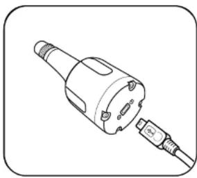
Line drawing of a mechanical connector or plug assembly (no text or symbols)1 Connect USB cable to SOA and PC
Remove the protective cap from the USB end of the SOA, and ensure that the connector is clean and dry. Then insert the small end of the provided USB cable into the SOA connector and the large, standard side into one of the PC's USB ports. The sonde should not be connected at this time.
Attaching the adapter to the PC causes a new device to be recognized. Windows automatically installs the drivers and creates a new port. Each new adapter that is attached creates a new port.
natural_image
Diagram of a mechanical component with an arrow indicating direction (no text or symbols present)2 Connect SOA to sonde
Remove the plug from the male 6-pin connector on the sonde. Apply a light layer of silicone grease to the male pins on the sonde and the female connector on the USB-SOA. Then align the connector's six pins and jackets, and press them firmly together so that no gap remains.
2.12
Communication Adapters
Data Collection Platform 2.0 (DCP)

text_image
DGP-30008 DCP-30008 DCP-30008 DCP-30008 DCP-30008 DCP-30008 DCP-30008 DCP-30008 DCP-30008 DCP-30008 DCP-30008 DCP-30008 DCP 300 DCP 300 DCP 300 DCP 300 DCP 300 DCP 300 DCP 300 DCP 300 DCP 300 DCP 300 DCP 300 DCP 300 DCP 300 DCP 300 DCP 300 ACODelivering quality data where and when you need it most.
Introduction:
The 599820 is a communication adapter for the EXO multiparameter sonde platform. It converts the proprietary signal from the water quality sonde into either SDI-12 or RS-232 signals. The adapter simplifies integration into 3rd party DCP systems, and also features a USB port that supports passthrough communication directly to the connected sonde. This feature allows configuration, calibration, and data transfer without having to disconnect the field cabling.

Adapter Overview:
Supply Power, 12 VDC Provided from external regulated power source (not included).
SDI-12 & RS-232 I/O Terminal Use either SDI-12 or RS-232 terminals.

Safety:
Do not attempt electrical wiring beyond your skill level. Follow all applicable code and regulations subject to electrical wiring and operation of the system.

text_image
Mini USB Connector Provide power to the adapter, and passthrough communication to the sonde. Signal Output Adapter DCP - Sonde EXOwater.com Part#: 599820 9-16VDC IN GND SHIELD 485-B 485-A (C) GND 232-TX 232-RX SDI-12 WHT BARE RED Status LED Magnetic Read Switch Used to rediscover attached sonde.
Getting Started
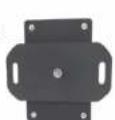
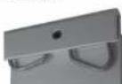
Mounting:
The adapter should be protected from the elements, and it is recommended it be mounted inside of a sealed enclosure with desiccant to prevent condensation.
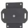
The adapter includes a panel mount in addition to self-adhesive hook and loop fastener. Either of these two methods can be used to securely mount the adapter. Use the provided Phillips screw to secure the panel mount:
Panel Mount Self-Adhesive Hook
1:


2:

Back Front
and Loop Fastener

NOTE: If using self-adhesive hook and loop, clean and dry both surfaces before applying.
NOTE: This adapter is not required for use of SDI-12 with an EXO3 or EXO3 ^® sonde.
It is, however, still required, if you need RS-232 communications.
| Status LED Indications | |
| Off No power | |
| On, no flashing No Sonde connected | |
| Flashing at 1 Hz Sonde connected, everything normal | |
| Flashing at 0.1 Hz | Low power sleep (Will flash on for 1 second when magnetic switch is activated.) |

Wiring
Have the
following ready:
- EXO Sonde
• DCP 2.0 Adapter
natural_image
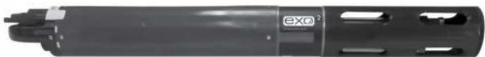
Exterior view of a cylindrical mechanical component with visible internal features and mounting holes (no text or symbols)
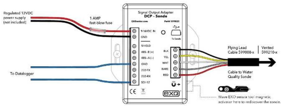
Wiring Continued
Next wire the flying lead cable, power, and DCP ports as labeled in one of the following configurations:
text_image
Regulated 12VDC power supply (not included) 1 AMP fast-blow fuse Signal Output Adapter DCP - Sonde EXOwater.com Port# 599020 9.16VDC IN GND SHIELD 485-A(-) 485-B(+) 485-A(-) GND 232-4X 232-RX SDI-12 BLK YEL WHT BARE RED To Scode Flying Lead Cable 599008-x Vented 599210-x To Datalogger Cable to Water Quality Sonde Wave EXO sensor tool magnetic activator here to rediscover the sonce.OR

text_image
Regulated 12VDC power supply (not included) 1 AMP fast-blow fuse Signal Output Adapter DCP - Sonde EXDwater.com Field 599920 9:16VDC IN GND SHIELD 485-B (+) 485-A (-) GND BLK YEL WHT Flying Lead Cable 599008 x Vented 599210 x
USB Passthrough Mode
The 599820 DCP Signal Output Adapter can function in a similar fashion as the 599810 USB communication adapter. After the Signal Output Adapter is wired as shown in the previous configuration, connecting to the USB port on the adapter will allow direct communications with the sonde using Kor Software. Make sure drivers are installed before attempting USB communication; see Section 3.2 for driver installation instructions.
flowchart
graph LR
    A["Laptop"] --> B["Router"]
    B --> C["Switch"]
    C --> D["Device 1"]
    C --> E["Device 2"]
NOTE: USB utilizes Communication Device Class (CDC) and installs as com port on PC: "YSI SOA/DCP Gen2". The USB connection may also be used to update firmware on the adaptor using Kor Software.

Output Configuration
In order to appropriately setup a sonde to communicate measurements to a data logger, it is critical to align the settings from the sonde and the logger. The default SDI-12 address is 0.
In the KorSoftware |Deployment Settings| choose the parameters and sort order, then push the template to the sonde.
The complete list of parameters is shown in the left column

text_image
Deployment Template Configuration Output Parameters B2.0000000000000000000000000000000000000000000000000000000000000000000000000000000000000000000000000000 B2.1.1.1.1.1.1.1.1.1.1.1.1.1.1.1.1.1.1.1.1.1.1.1.1.1.1.1.1.1.1.1.1.1.1.1.1.1.1.1.1.1.1.1.1.1.1.1.1.1.1.2 B2.2.2.2.2.2.2.2.2.2.2.2.2.2.2.2.2.2.2.2.2.2.2.2.2.2.2.2.2.2.2.2.2.2.2.2.2 B2.3.3.3.3.3.3.3.3.3.3.3.3.3.3.3.3.3.3.3.3.3.3.3 B2.4.4.4.4.4.4.4.4.4.4.4.4.4.4.4.4.4. B2.5.5.5.5.5.5.5.5.5.5.5.5. B2.6.6.6.6.6.6.6.6.6. B2.7. B2.8. B2.9. B3. B4. B5. B6. B7. B8. B9. B10. B11. B12. B13. B14. B15. B16. B17. B18. B19. B20. B21. B22. B23. B24. B25. B26. B27. B28. B29. B30. B31. B32. B33. B34. B35. B36. B37. B38. B39. B40. B41. B42. B43. B44. B45. B46. B47. B48. B49. B50. B51. B52. B53. B54. B55. B56. B57. B58. B59. B60. B61. B62. B63. B64. B65. B66. B67. B68. B69. B70. B71. B72. B73. B74. B75. B76. B77. B78. B79. B80. B81. B82. B83. B84. B85. B86. B87. B88. B89. B90. B91. B92. B93. B94. B95. B96. B97. B98. B99. C Output ParametersEXO DCP Signal Output Adapter Programming Basics
1. SDI-12 Interface
- General
- Compatible with v1.3 of
SDI-12 specification
• Supports following standard commands:
• 'I' Address Query
• 'A' Change Address
• 'C' Concurrent Measurement
• 'D' Data
• 'I' Identification
• 'M' Start Measurement
• 'V' Start Verification
- Extended Commands
- SDI-12 'Z' command
SDI-12 Command List
| Name Command Response and Description | ||
| Address Query ?! | a | Request the address of the sonde "a"The protocol framing "" may or may not be present. |
| Acknowledge Active | a! | aCheck to see if the sonde is responsive. |
| Change Address | aAb! | bChange a sensor's address. "b" is the new sensor address. |
| Send Identification | all | allYSIIWQSGEXOSNDvvvQuery for sensor information. "ll" is the SDI-12 version. "YSI-IWQSG" is the vendor ID. "EXOSND" is the model. "vvv" is the version number. |
| Sonde Serial Number Query aZSN! aSN^M | ^Jnnnnnnnnn^M^J#_ | Returns the sonde serial number, "nnnnnnnnn" "^M^J" and "^M^J#" are protocol framing. |
| Parameter List Query aZPARAI aPARA^M | Jn_nn_nnn_..^M^J#_ | Returns the list of parameter codes, "n", "nn", or "nnn" as defined in Section 2.14, corresponding to the data values returned in the M or C commands. |
| Start Wipe Cycle aZTWIPEB! | aTWIPEB^M^J45^M^J#_ | Send command to start a sensor wipe cycle using Central Wiper. "45" indicates it will take 45 seconds to perform the wipe. |
| Software Version Query | aZVER! | aVER^M^Jn.n.nn^M^J#_Returns the sonde firmware version, "n.n.nnn" |
| Sensor Serial Number Query | aZSSN! | aSSN^M^Jnnnnnnnnn_..^M^J#_Returns the serial numbers of all sensors installed in the sonde, "nnnnnnnnn" as a list. Follow with command aZ! to list remaining SNs in the string. |
2. RS-232 Interface
- General
- Command Line
-
is user prompt
- Commands are not case sensitive
- Only spaces are recognized as delimiters
- A command is terminated by a
• Minimum time from power up to valid readings is 19 seconds - Extended Commands:
natural_image
Black-and-white photo of a river with a large suspension bridge and a small boat on the water, viewed from a viewing platform (no visible text or symbols)2.13
Communication Adapters
RS-232
The EXO DCP Signal Output Adapter (SOA) supports limited RS-232 commands. The SOA supports both SDI-12 and RS-232 communications. The order of the RS-232 parameter output is controlled by the SDI-12 tab on the deployment menu.
[] indicates argument is optional indicates argument is an integer
data
Returns one line of data readings. Data parameters specified in para command. Data delimiter is specified in the setdelim command.
dowait []
Turns "wait for DO" on if =1 and off if =0 . The response is "OK". If you do not supply , then the response is the current value of dowait. When enabled the SOA/DCP will not return data until sonde has been on for "dowarmup" seconds.
dowarmup []
Sets DO sensor warmup time where =warmup time in seconds. The response is "OK". If you do not supply , then the response is the current value for dowarmup. When "dowait" is enabled the SOA/DCF will not return data until sonde has been on for "dowarmup" seconds.
fltreset
Resets all sonde sensor filters. The response is "OK".
hwipesleft
Returns a value other than 0 if a wiper event is in progress.
pwruptorun []
Turns "power up to run" on if <i>=1 and off if <i>=0 . The response is "OK". If you do not supply <i> , then the response is the current value of pwruptorun.
run
Causes the sonde to SOA/DCP to take sonde readings at a 1Hz rate. The output is similar to the Data command except that readings are taken continuously. No headers are output. To abort send '0',
setcomm [] []
Changes the SOA/DCP's comm port baud rate and data length. The baud rate will be immediately changed after this command, so you will need to reconfigure your terminal to match.
can be:
2 - 1200 baud 6 - 19200 baud
3 - 2400 baud 7 - 38400 baud
4 - 4800 baud 8 - 57600 baud
setdelim []
Changes the SOA/DCP's delimiter used in the data command response. If you do not supply , then the response is the current value for delimiter.
can be: 0 = space, 1 = TAB, 2 = comma, 3 = none
setecho []
Enables (=1) or disables (=0) command echoes. When echoes are disabled, commands sent to the SOA/DCP will not be 'echoed' back and there will be no '#' prompt. If you do not supply , then the response is the current value for echo.
setmode []
Sets the RS-232 mode. If =0 , mode is normal. If =1 mode is NMEA. If you do not supply , then the response is the current value for mode.
setradix []
Sets the radix point used for data output. If (=0) radix will be '('. If (=1) radix will be '('. Note that in SDI-12 mode, the response to a 'D' command will always be with '('. regardless of this setting. The response is "OK". If you do not supply (), then the response is the current value for radix.
setsonde []
Selects a sonde for RS-232 communications when sondes are daisy-chained. represents the order of the sonde in the chain where 1st sonde = 0, 2nd = 1, 3rd = 2. The response is "OK". If you do not supply , then the response is the current value for the sonde.
setperiod []
Sets the period for the data output in RUN mode. The period is set to milliseconds. Minimum value is 250 (1/4 second), maximum value is 30000 (30 seconds). If you do not supply , then the response is the current value for period. For periods less than 1000 and baud rates below 9600, the data output may be unreliable.
time []
Allows user to set time in the sonde in the HH:MM:SS format. The response is "OK". If you do not supply
twipeb
Starts a wiper event. The response is the approximate time in seconds it will take to perform the wipe.
ver
Returns the software version number of the sonde.
verdate
Returns the time and date at which the current version of software in the sonde was compiled.

text_image
DCP-Sonde Signal Output Adapter RS-232 Baud Rate 9600 Parity None Data Bits 82.14
Communication Adapters
SDI-12
The sonde can be connected to an SDI-12 bus using a DCP Signal Output Adapter (SOA). The SOA provides the necessary SDI-12 electrical interface and communicates to the sonde via the topside RS-485 interface. The SOA will automatically recognize when a sonde is connected and retrieve the SDI-12 address and ID from the sonde. The SDI-12 data parameter list is set by the user in the Deploy menu. Go to Deploy | Open Template | Edit Template menu and click on the SDI-12 tab.
• Maximum of 23 codes in sonde parameter list.
| Parameter Code | |
| Temperature, °C 1 | |
| Temperature, °F 2 | |
| Temperature, K | 3 |
| Conductivity, mS/cm 4 | |
| Conductivity, μS/cm 5 | |
| Specific Conductance, mS/cm | 6 |
| Specific Conductance, μS/cm | 7 |
| TDS, g/L 10 | |
| Salinity, PPT 12 | |
| pH, mV 17 | |
| pH 18 | |
| ORP, mV 19 |
| Parameter | Code |
| Date, YYMMDD, | 53 |
| Time, HHMMSS | 54 |
| TDS, kg/L | 95 |
| NO3 (Nitrate), mV | 101 |
| NO3 (Nitrate), mg/L | 106 |
| NH4 (Ammonium), mV | 108 |
| TDS, mg/L | 110 |
| Chlorido, mg/L | 112 |
| Chlorido, mV | 145 |
| TSS, mg/L | 190 |
| TSS, g/L 191 | |
| Chlorophyll, μg/L | 193 |
| Parameter | Code |
| TAL-PE, RFU | 218 |
| Turbidity, FNU | 223 |
| TAL-PC, μg/L | 225 |
| TAL-PE, μg/L | 226 |
| fDOM, RFU | 227 |
| IDOM, QSU | 228 |
| Wiper Position, V | 229 |
| External Power, V | 230 |
| nLF Conductivity, mS/cm | 237 |
| nLF Conductivity, μS/cm | 238 |
| Wiper Peak Current, mA | 239 |
| Vertical Position, m | 240 |
2.15
Communication Adapters
Modbus
natural_image
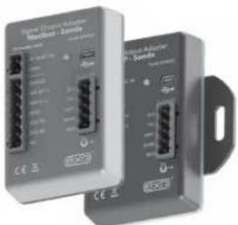
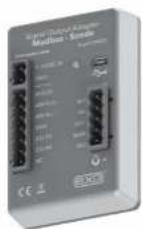
Two industrial electronic devices labeled 'Power Chain Adapter P. Scode' with ports and connectors (no visible text beyond labels)Delivering quality data where and when you need it most.
Introduction:
The 599825 is a communication adapter for the EXO multiparameter sonde platform. It converts the proprietary signal from the water quality sonde into a Modbus protocol over either RS 232 or RS-485 signals. The adapter simplifies integration into 3rd party SCADA systems, and also features a USB port that supports passthrough communication directly to the connected sonde. This feature allows configuration, calibration, and data transfer without having to disconnect the field cabling.

Adapter Overview:
Supply Power, 12 VDC Provided from external regulated power source (not included).
Modbus I/O Terminal Use either 485 (default) or RS-232 terminals.

Safety:
Do not attempt electrical wiring beyond your skill level. Follow all applicable code and regulations subject to electrical wiring and operation of the system.
Mini USB Connector
Used to configure adapter settings, provide power to the adapter, and passthrough communication to the attached sonde.

text_image
Signal Output Adapter Modbus - Sonde EXOwater.com 9-16VDC IN GND SHIELD 485-B (+) 485-A (-) GND 232-TX 232-RX NC Status LED YEL WHT BARE RED Magnetic Read Switch Used to rediscover attached sonde.
Getting Started
Mounting:
The adapter should be protected from the elements, and it is recommended it be mounted inside of a sealed enclosure with desiccant to prevent condensation.
The adapter includes a panel mount or a DIN rail mount in addition to self-adhesive hook and loop fastener. Any of the three methods can be used to securely mount the adapter. Use the provided Phillips screw to secure the panel or din rail mount:
Panel Mount
1:

2:

Back Front
DIN Rail Mount
| Status LED Indications | |
| Off No power | |
| On No Sonde connected | |
| Flashing at 1 Hz Sonde connected, everything normal | |
| Flashing at 1/10 Hz | Low power sleep (Will flash on for 1 second when magnetic switch is activated.) |
Configuration:
Connecting to the SOA Modbus Adapter:
Download the latest version of Kor Software from the YSI Software Downloads page. Disconnect the EXO from Kor before connecting the SOA via USB. With the SOA Modbus powered and connected via USB, click 'Manage Communication Adapters' under the |Instrument and Sensors| tab.

text_image
Modbus-Sonde Signal Output Adapter Input Type: Modbus Input: Size Range: 1000 Size: 500 Size Rate: 0 Size Rate: 0 Output: Size Range: 1000 Size Rate: 0 Output: Output: Output: Output: Output: Output: Output: Output: Output: Output: Output: Output: Output: Output: Output: Output: Output: Output: Output: Output: Output: Output: Output: Output: Output: Output: Output: Output: Output: Output: Output: Output: Output: Output: Output: Output: Output: Output: Output: Output: Output: Output: Output: Output: Output: Output: Output: Output: Output: Output: Output:Configuring the SOA Modbus Adapter
Once you are connected, Kor retrieves all of the current settings and displays them. To change a setting, modify the value of interest and click 'Apply All Settings.'

Wiring
Have the following ready:
• EXO Sonde
- Com Adapter
- Flying Lead Cable
- Flat blade screwdriver
• Power & SCADA Wires
natural_image
Exterior view of a cylindrical mechanical component with cutouts and a small label 'exo²' on the side (no other text or symbols visible)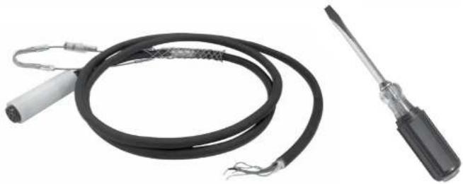
natural_image
Two types of electrical probes: a black coiled wire with terminal connectors and a black screwdriver (no text or symbols visible)
Next wire the flying lead cable, power, and Modbus ports as labeled:
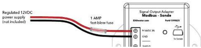
text_image
Regulated 12VDC power supply (not included) 1 AMP fast-blow fuse Signal Output Adapter Medbus - Sonde EXDwater.com Ford 119825 +1-5VDC IN GND To Sense
USB Passthrough Mode
The 599825 Modbus Adapter can function in a similar fashion as the 599810 USB communication adapter. It will power the device and provide limited power to the sonde. After the Modbus adapter is wired as shown in the previous configuration, connecting to the USB port will allow direct communications with the sonde using Kor Software.

flowchart
graph LR
    A["Laptop with 'Kor' icon"] --> B["USB"]
    B --> C["Device with USB cable"]
    C --> D["Wire cable"]
NOTE: USB utilizes Communication Device Class (CDC) and installs as com port on PC: "YSI SOA/DCP Gen2". The USB connection may also be used to update firmware on the adapter using Kor Software.

General Modbus Information
- Register references are to the typical Holding Registers. Depending on your SCADA system these may be the 400,000 registers, the 40,000 registers, or simply the register values defined in this document. In this document the register value will generally be used. In all cases the register value will be +1 from the address value.
- The Output adapter makes use of the Modbus Holding register system to transfer data. It will respond to the Modbus commands "Read Holding Registers", "Write Single Register" and "Preset Multiple Registers". For all other commands the 599825 Modbus Adapter will return an illegal function exception. In general if you attempt to read or write from to a reserved or unused area, the 599825 Modbus adapter will
- There are 3 main register areas to deal with the parameters:
- Parameter type
- Parameter status
- IEEE floating point parameter data (Scaled integer parameter data, available but not recommended for use.)
Each of these areas is 32 registers long, except for the floating point data area which is 32 register pairs long. The first register (or register pair for the floating point data) in each area corresponds to the first parameter, the second corresponds to the second parameter, etc.

General Modbus Information
| 40,000 Read Holding Address | 40,000 Read Holding Register | Read/Write | Description |
| 0 | 1 | Read/Write Single Reg | Sample Period: The period in seconds at which the SOA will sample the sonde data and update holding registers (value between 0-3600) |
| 1 | 2 | Write Only Single Reg | Force Sample: Write any value here to force the SOA to update holding registers with sonde data allow 15 seconds for values to show up in data registers |
| 2 | 3 | Write Only Single Reg | Force Wipe: Write any value here to force the connected sonde to run its wiper |
| 3-127 4-128 -- Unused - reserved for future special functions | |||
| 128-159 129-160 Read/Write | Parameter type: The PLC must write to this area to tell the SOA what parameters it wants. Up to 32 parameters can be written here. After the last parameter the PLC must write a "0. The table on the "Available Parameters Codes" page lists the valid parameter type codes. | ||
| 160-225 161-256 -- Reserved for future parameter type | |||
| 256-287 257-288 Read Only | Parameter status: The PLC can read back the values in these registers to check the status of the parameters. The value in register 257 corresponds to the parameter type in register 129 and so on. The meaning of the returned value is:0 - The parameter is available.1 - The parameter type has not been set (i.e. type = 0)2 - The parameter requested is not currently available. | ||
| 288-383 289-384 -- Reserved for future parameter status | |||
| 384-447 385-448 Read Only | IEEE 754 Floating point parameter data: This is the actual parameter data in floating point form. Two registers are used for each value to make up the 32 bits required for a 4 byte IEEE floating point number. The value in register pair 385:386 corresponds to the parameter type in register 129 and so on. It is highly recommended that this be used rather than the scaled integer format. | ||
| 448-639 449-640 -- Reserved for future IEEE floating point parameter data | |||
| Scaled Integer parameter data: The PLC should only read data from the SOA using this method if it cannot handle floating point data. Most PLCs can manipulate floating point values, so you should try to avoid reading scaled integer values. The value in register 641 corresponds to the parameter type in register 129 and so on. The values | |||

Registry Configuration
This section deals with mapping the water quality parameter types to the respective holding register 129-160. These are the measurement values generated by the water quality sonde. There are two methods to set the parameter map. The preferred method is to use the deployment templates available in any version of Kor. This standard functionality allows the parameters to be selected and saved. Alternatively, the registers may be directly written by the SCADA system.
In Kor Software |Deployment Settings| choose the parameters and sort order, then push the template to the sonde.
The complete list of parameters is shown in the left column and the selected parameters to output via the Modbus adapter are shown on the right. This template can be saved locally on the PC, but it must also be pushed down to the sonde for the settings to take effect. So be sure to apply the template to the sonde.
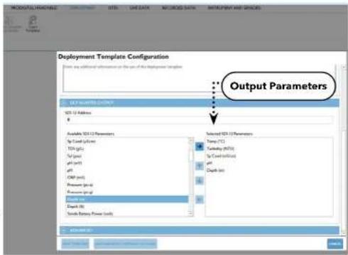
text_image
Deployment Template Configuration Start any additional information on the use of this Deployment Template Output Parameters ISO 12 Address Available ISO 12 Parameters Up Load (ppm) Down (ppm) Up (ppm) pH (ppm) pH (ppm) CMB (ppm) Pressure (ppm) Pressure (ppm) Dialysis (ppm) Direct (ppm) Send Battery Power (kW) Selected ISO 12 Parameters Temp (°C) Turbidity (MHz) Up Load (kHz) pH Depth (mm) Output Parameters End Subs End SubsNOTE: When deploying with connection to a SCADA system, use the 'Sample and Hold' logging mode to create a redundant log file inside the sonde. In 'Normal' mode the data will only be available to the SCADA system. See Section 3.7 for more information.
In the example below: Temp °C, Turbidity, SpCond, pH, and Depth M were chosen. This will automatically create a register map as follows:

Available Parameter Codes
The alternative setup method is to write these parameter codes using the SCADA system in the format indicated. The table below is the reference list of all available parameter codes for Read Holding Registers 129-160.
| Parameter Code | |
| Temperature, °C 1 | |
| Temperature, °F 2 | |
| Temperature, K | 3 |
| Conductivity, mS/cm 4 | |
| Conductivity, μS/cm 5 | |
| Specific Conductance, mS/cm | 6 |
| Specific Conductance, μS/cm | 7 |
| TDS, g/L 10 | |
| Salinity, PPT 12 | |
| pH, mV 17 | |
| pH 18 | |
| ORP, mV 19 | |
| Pressure, psia 20 | |
| Pressure, psig 21 | |
| Depth, m 22 | |
| Depth, ft 23 |
| Parameter Code | |
| Date, YYMMDD, | 53 |
| Time, HHMMSS | 54 |
| TDS, kg/L | 95 |
| NO3 (Nitrate), mV | 101 |
| NO3 (Nitrate), mg/L | 106 |
| NH4 (Ammonium), mV | 108 |
| TDS, mg/L | 110 |
| Chloride, mg/L | 112 |
| Chloride, mV | 145 |
| TSS, mg/L | 190 |
| TSS, g/L 191 | |
| Chlorophyll, μg/L | 193 |
| Chlorophyll, RFU | 194 |
| PAR, Channel 1 | 201 |
| PAR, Channel 2 | 202 |
| Rhodamine, μg/L | 204 |
| Parameter | Code |
| TAL-PE, RFU | 218 |
| Turbidity, FNU | 223 |
| TAL-PC, μg/L | 225 |
| TAL-PE, μg/L | 226 |
| fDOM, RFU | 227 |
| fDOM, OSU | 228 |
| Wiper Position, V | 229 |
| External Power, V | 230 |
| nLF Conductivity, mS/cm | 237 |
| nLF Conductivity, μS/cm | 238 |
| Wiper Peak Current, mA | 239 |
| Vertical Position, m | 240 |
| Vertical Position, ft | 241 |
| Chlorophyll, cells/mL | 242 |
| NitraLED, mg/L | 243 |
The subsequent values for the parameter map are displayed in IEEE floating point parameter format (IEEE 754). The Parameter data is stored in read only address 385-448. Two address are used for each value to make up the 32 bits required for a 4 byte IEEE floating point number. The value in address pair 385:386 corresponds to the parameter type in register 129, etc.
In our example let's assume the following values:
Temp 25.11°C, Turbidity 2.34 FNU, SpCond 3.02 ms/cm, pH 7.23, and Depth 1.45 M
| Read Holding Address | Read Holding Register | Read/Write | Value (IEEE 754) | Description |
| 384 | 385 | Read | 0xE147 | The least significant 16 bits of the 32-bit floating point value for 25.11 |
| 385 | 386 | Read | 0x41C8 | The most significant 16 bits of the 32-bit floating point value for 25.11 |
| 386 | 387 | Read | 0x47AE | The least significant 16 bits of the 32-bit floating point value for 3.02 |
| 387 | 388 | Read | 0x4041 | The most significant 16 bits of the 32-bit floating point value for 3.02 |
| 388 | 389 | Read | 0x5C29 | The least significant 16 bits of the 32-bit floating point value for 7.23 |
| 389 | 390 | Read | 0x40E7 | The most significant 16 bits of the 32-bit floating point value for 7.23 |
Advanced Configuration
The 599825 Modbus adapter will automatically sleep after 60 seconds of not being queried. To prevent the adapter from sleeping, query the adapter more frequently than 60 seconds. Alternatively program a sample interval into register 1. This is the interval the 599825 Modbus adapter will refresh its readings from the underwater sonde. It can be advantageous to sample at a 10 or 15 minute interval to extend the life of the sensors.
As an example a 10 minute (600 second) sample value in register 1 will query the sonde every 10 minutes to refresh the values in 385-448 IEE floating point registers. It is recommended you program a sample interval into the 599825 Modbus adapter half that of your scan interval. As an example if your SCADA will query the adapter every 20 minutes (1200 seconds) then it is recommended you write a 10 minute (600 seconds) sample value in address 1. This methodology will ensure the queried data is never more than 10 minutes old.
Activating the wiper: The EXO2/3 system can be equipped with a Central Wiper to clean the sensors. There are two different mechanisms to activate the wiper.
The first is to write any number into register #3, this will trigger the EXO sonde to wipe the sensors in both directions. 60 seconds should

Scaled Integer Range Table
| Parameter Code | Scale Low | Scale High | |
| Temperature, °C 1 -50 60 | 5.35 | ||
| Temperature, °F 2 -50 60 | 5.35 | ||
| Temperature, K | 3 0 6 | 55.35 | |
| Conductivity, mS/cm 4 0 | 655.35 | ||
| Conductivity, μS/cm 5 0 | 65535 | ||
| Specific Conductance, mS/cm | 6 0 6 | 55.35 | |
| Specific Conductance, μS/cm | 7 0 6 | 5535 | |
| TDS, g/L 10 0 65.535 | |||
| Salinity, PPT 12 0 65.535 | |||
| pH, mV 17 -1638.4 | 1638.35 | ||
| pH | 18 -27 | 7.768 | 39.767 |
| ORP, mV 19 -1638.4 | 1638.35 | ||
| Pressure, psia | 20 | -50 605 | 35 |
| Pressure, psig | 21 | -50 605 | 35 |
| Depth, m | 22 | -50 605 | 35 |
| Depth, ft | 23 | -50 605 | 35 |
| Battery, V | 28 0 6 | 5.535 | |
| Turbidity, NTU | 37 0 6 | 553.5 | |
| NH3 (Ammonia), mg/L | 47 0 6 | 55.35 | |
| NH4 (Ammonium), mg/L | 48 0 6 | 55.35 | |
| Date, DDMMYY 51 | N/A | N/A | |
| Date, MMDDYY | 52 | N/A N/A | |
| Date, YMMDDY | 53 | N/A N/A |
| Parameter | Code | Scale Low | Scale High |
| Chloride, mV | 145 | -1638.4 | 1638.35 |
| TSS, mg/L | 190 | 0 6553.5 | |
| TSS, g/L | 191 | 0 6.5535 | |
| Chlorophyll, μg/L | 193 | 0 655.35 | |
| Chlorophyll, RFU | 194 | 0 655.35 | |
| Rhodamine, μg/L | 204 | 0 6553.5 | |
| ODO, %Sat | 211 | 0 655.35 | |
| ODO, mg/L | 212 | 0 | 65.535 |
| ODO, %Sat Local | 214 | 0 | 655.35 |
| TAL-PC, RFU | 216 | 0 | 655.35 |
| TAL-PE, RFU | 218 | 0 | 655.35 |
| Turbidity, FNU | 223 | 0 | 6553.5 |
| TAL-PC, μg/L | 225 | 0 | 655.35 |
| TAL-PE, μg/L | 226 | 0 | 655.35 |
| fDOM, RFU | 227 | 0 | 655.35 |
| fDOM, QSU | 228 | 0 | 655.35 |
| Wiper Position, V | 229 | 0 | 65.535 |
| External Power, V | 230 | 0 65.535 | |
| nLF Conductivity, mS/cm | 237 | 0 | 655.35 |
| nLF Conductivity, μS/cm | 238 | 0 | 65535 |
| Wiper Peak Current, mA | 239 | 0 | 65.535 |
| Vertical Position, m | 240 | -50 605.35 |
2.16
Connect Sonde
Flow Cell
There are two versions of the EXO flow cell: EXO1/EXO1 ^5 flow cell (part #599080) and EXO2/EXO2 ^5 /EXO3/EXO3 ^5 flow cell [599201]. Flow rate through the flow cell is typically between 100 mL and 1 L per minute. Maximum flow rate depends on tubing type, size, and length. Maximum pressure for each flow cell is 25 psi. Flow cell volumes (without sensors installed) are approximately 410 mL for EXO1/EXO1 ^5 , and 925 mL for EXO2/EXO2 ^5 and EXO3/EXO3 ^5 .
text_image
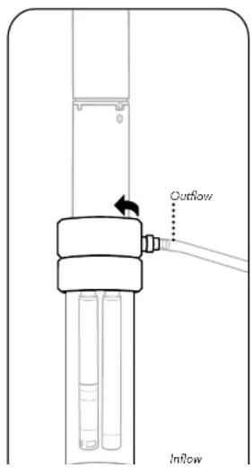
Outflow Inflow1 Inspect sonde and flow cell
Remove the sensor guard and/or calibration cup so that the sensors are exposed.
Make sure that the threads of the sonde and flow cell as well as all o-rings are clean and free of any particles such as sand, grit, or dirt.
2 Insert sonde into flow cell
Insert the sonde into the top of the flow cell. Be careful not to bump or scrape the sensors on the sides of the flow cell.
Screw the sonde into the flow cell by turning the sonde clockwise until it is hand-tightened into place; do not use a tool.
3 Connect tubing to flow cell
Install the Quick Connect tube fittings onto the flow cell by inserting them into the Quick Connect coupling body. They should snap into place.
Connect the tubing from your pump (not included) to the Quick Connect tube fittings, making sure that the tubing is pushed securely onto the fittings. The

Daisy Chaining
Sonde Expansion
It is possible to daisy chain up to three EXO2/EXO2 ^b sondes using the built-in topside auxiliary port. Below is a quick start guide for setting up sondes for long-term deployment in this application.
NOTE: Daisy chaining is only possible with EXO2 and EXO2 ^5 sondes.
NOTE: These instructions are for the DCP-SOA 1.0. With the new 2.0 model, you no longer have to be this meticulous about the order in which you connect the instruments. Simply hook all the components together and then use the magnetic activation on the side of the DCP-SOA 2.0 to allow it to reset and rebuild the map.

text_image
Subtemplate Template Configuration File path: C:\Program Files\123\Program Files\123\Program Files\123\Program Files\123\Program Files\123\Program Files\123\Program Files\123\Program Files\123\Program Files\123\Program Files\123\Program Files\123\Program Files\123\Program Files\123\Program Files\123\Program Files\123\ProgramFiles\123\Program Files\123\Program Files\123\Program Files\123\Program Files\123\Program Files\123\Program Files\123\Program Files\123\Program Files\123\Program Files\123\Program Files\123\Program Files\123\Program Files\123\Program Files\123\Program Files\90000000000000000000000000000000000000000000000000000000000000000000000000000000000000000000000000000 Subtemplate Templates File Path: C:\Program Files\123\Program Files\123\Program Files\123\Program Files\123\Program Files\123\Program Files\123\Program Files\123\Program Files\123\Program Files\123\Program Files\123\Program Files\123\Program Files\123\Program Files\123 Subtemplate Templates File Path: C:\Program Files\123\Program Files\123\Program Files\123\Program Files\123\Program Files\123\Program Files\123\Program Files\123\Program Files\123 Subtemplate Templates File Path: C:\Program Files\123\Program Files\123\Program Files\123\Program Files\123\Program Files\123 Subtemplate Templates File Path: C:\Program Files\123\Program Files\123\Program Files\123 Subtemplate Templates File Path: C:\Program Files\123\Program Files\123 Subtemplate Templates File Path: C:\Program Files\123\Program Files\123 Subtemplate Templates File Path: C:\Program Files\123 Subtemplate Templates File Path: C:\Program Files\123 Subtemplate Templates File Path: C:\Program Files\123 Subtemplate Templates File Path: C:\Program Files\123 Subtemplate Templates File Path: C:\Program Files\123 Subtemplate Templates File Path: C:\Program Files\123 Subtemplate Templates File Path: C:\Program Files\645 Subtemplate Templates File Path: C:\Program Files\645 Subtemplate Templates File Path: C:\Program Files\645 Subtemplate Templates File Path: C:\Program Files\645 Subtemplate Templates File Path: C:\Program Files\645 Subtemplate Templates File Path: C:\Program Files\645 Subtemplate Templates File Path: C:\Program Files\n645 Subtemplate Templates File Path: C:\Program Files\n645 Subtemplate Templates File Path: C:\Program Files\n645 Subtemplate Templates File Path: C:\Program Files\n645 Subtemplate Templates File Path: C:\Program Files\n645 Subtemplate Templates File Path: C:\Program Files\n645 Subtemplate Templates File Path: C:\Program Files\n6451 Set Deployment Times
Connect to each sonde individually via Kor. One by one, use the Deploy menu to Read Current Sonde Settings and make changes to the deployment templates. If using SDI-12 communications (recommended), set each sonde with a unique SDI-12 address.
2 Connect the Sondes
Remove power from the DCP adapter and remove all batteries from the instruments, then connect the 2-3 sondes in series using standard EXO field cables (connecting one sonde's communications connector with another sonde's topside auxiliary port).
NOTE: Total cable length cannot exceed 300 m, and the sondes themselves cannot exceed 250 m depth.
text_image
Auxiliary Port 6-Pin3 Connect Sondes to SOA-DCP
Using a flying lead cable, connect the topmost sonde to an EXO DCP Signal Output Adapter. Install batteries in the sonde furthest from the DCP adapter first. Then install batteries in the next sonde furthest from the adapter and then the sonde closest to
2.18
Sonde Clamping / Mooring
Long-Term Monitoring
In long-term monitoring applications, where the sonde will be left unattended for long periods of time, it is critical that you properly mount and protect your EXO sonde. This will ensure you receive quality data and that your instrument is not lost in a flood or other natural event. While there are many options available to you to secure your sonde for long-term monitoring, including mooring cages and protective housing, below you will find a general guide for the most common method - the deployment tube.
Vertical Deployment Tube
The most common configuration for a deployment tube, typically off a pier or other fixed location. Highly recommended for the highest quality data as it ensures a proper flow of water to the sensors, and avoids stagnation.
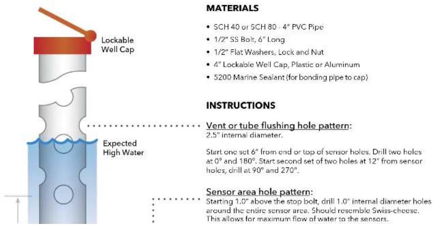
text_image
MATERIALS • SCH 40 or SCH 80 - 4" PVC Pipe • 1/2" SS Bolt, 6" Long • 1/2" Flat Washers, Lock and Nut • 4" Lockable Well Cap, Plastic or Aluminum • 5200 Marine Sealant (for bonding pipe to cap) INSTRUCTIONS • Vent or tube flushing hole pattern: 2.5" internal diameter. Expected High Water Start one set 6" from end or top of sensor holes. Drill two holes at 0° and 180°. Start second set of two holes at 12" from sensor holes, drill at 90° and 270°. Sensor area hole pattern: Starting 1.0" above the stop bolt, drill 1.0" internal diameter holes around the entire sensor area. Should resemble Swiss-cheese. This allows for maximum flow of water to the sensors.Horizontal Deployment Tube
In shallow water applications it is possible to deploy your EXO sonde horizontally. However, care must be taken that the sensors stay submerged and hydrated. This configuration has inherent risks such as sediment build up and is somewhat susceptible to flooding events even when properly fixed in place.
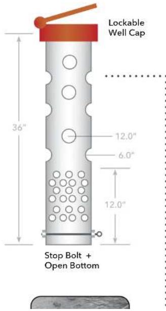
text_image
Lockable Well Cap 36" 12.0" 6.0" 12.0" Stop Bolt + Open BottomMATERIALS
• SCH 40 or SCH 80 - 4" PVC Pipe, 36" Long
• 1/2" SS Bolt or Eye Bolt, 6" Long
• 1/2" Flat Washers, Lock and Nut
- 4^th Lockable Well Cap, Plastic or Aluminum
• 5200 Marine Sealant (for bonding pipe to cap)
- Two heavy weighted slabs to support pipe
Chain to fixed object or anchor on shore
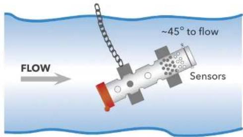
text_image
~45° to flow Sensors FLOWINSTRUCTIONS
Vent or tube flushing hole pattern:
Sonde Clamping Guide
Great care should be taken when securing an EXO sonde to other objects. The preference is to deploy the sonde inside of a PVC pipe without clamps as described previously. However, if clamping is desired, the sonde should never be mounted directly to a mooring line, steel cable or piling as the pressure from a band clamp will deform the sonde and potentially cause leaks.
NOTICE: Damage and leaks from improper clamping is not covered under warranty.
Preferred Clamping Areas

text_image
Recommended Clamp Design Provides Even Pressure Incorrect Clamping NOTICE: Under pressure from the band clamp, the sonde can become oblong, causing failure of the o-rings. Cable Cable Sonde Sond Band Clamp Band Clamp
natural_image
Black-and-white photo of a laptop and a cylindrical device on a workbench, with no visible text or symbols.3.1
Kor Software
Introduction

Interfacing with Kor Software Watch Videos Now
Kor Software and drivers require permissions for successful installation. Administrative privileges may be necessary for a business or networked PC.
System Requirements
Supported 32 bit (x86) and 64 bit (x64) Microsoft Operating Systems:
• Microsoft Windows 10 Home
• Microsoft Windows 10 Professional
• Microsoft Windows 10 Enterprise
• Microsoft Windows 10 Education
• Microsoft Windows 11 Home
• Microsoft Windows 11 Pro
• Microsoft Windows 11 Enterprise
• Microsoft Windows 11 Education
Ram Memory Requirement:
• Minimum of 2 GB of RAM installed
Hard Disk Free Space:
• Minimum of 500 MB of free hard drive space
Screen Resolution:
- 1024x768 or higher

Kor Software
Installation
Kor Software is supplied with all EXO Sondes on a USB flash drive. Installation will require administrative privileges.
NOTE: It is important to install Kor Software prior to connecting EXO hardware, as the required drivers are installed along with the software.
Follow these steps to complete the installation process:
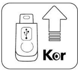
text_image
Kor- Insert the supplied USB flash drive into a USB port on your computer.
- Double-click Start.exe in the EXO DRIVE window to launch the installer.
- Click INSTALL DRIVERS and click INSTALL ALL to install all EXO hardware drivers. Follow the prompts to complete each driver installation.
NOTE: Administrative Privileges are needed to perform each driver installation.
- After drivers are installed, click BACK to return to the Kor Installer main menu.
- Click INSTALL APPLICATION and check the box to agree to license terms and conditions, and then click INSTALL.
NOTE: Administrative Privileges are needed to perform the software installation.
- After successful installation, close the Installer.
- Open the Kor Software program for the first time. You may be asked if you want to allow a program from an unknown publisher to make changes on the computer. If so, select YES.
NOTE: Administrative Privileges may be needed to run Kor Software for the first time; Administrative Privileges will not be needed for subsequent launches of the software.
Installation Troubleshooting:
Issue - Software Crash Solution

Kor Software
Instrument Connection Panel
Kor Software connection to any EXO device is established through the Instrument Connection Panel. There are two types of connection:
- Wired via USB cable
- Wireless via Bluetooth (not available for EXO Handheld)
Wired Connection:
There are a few ways to establish a wired connection to an EXO Sonde. The most common method involves using a USB Signal Output Adapter (SOA) which plugs into the sonde directly. Alternatively, one can use the EXO Handheld or EXO GO which connects to the sonde via a field cable and connects to the computer via a USB cable. The following instructions pertain to connection via the USB SOA:

natural_image
Line drawing of a mechanical connector with a cable inserted (no text or symbols)1 Connect the USB Cable to the Signal Output Adapter (SOA) and the PC
Remove the protective cap from the USB end of the SOA, and ensure that the connector is clean and dry. Insert the Mini USB end of the cable into the SOA connector and the USB A end of the cable into one of the PC's USB ports. The sonde should not be connected at this time.
Attaching the adapter to the PC causes a new device to be recognized. Windows automatically installs the drivers and creates a new COM port. Each new adapter that is attached creates a new COM port. To confirm that the SOA is successfully recognized as a COM port, open the Device Manager on the PC and view it under Ports.

2 Connect the SOA to the EXO Sonde
Remove the plug from the male 6-pin connector on the sonde. Apply a light layer of Silicone grease to the male pins on the sonde and the female connector on the USB-
Wireless Connection:
Every EXO Sonde includes a built-in Bluetooth chip which allows for wireless communication with a computer or mobile device that has Bluetooth capabilities. This is extremely convenient for calibration and sampling at the surface level. However, the Bluetooth communication is severed when the sonde is submerged under water. EXO GO provides a Bluetooth connection to an EXO Sonde that may be submerged. The following instructions pertain to connection via the EXO Sonde's internal Bluetooth.
NOTE: To wirelessly connect to an EXO Sonde, your computer must either have internal Bluetooth or a USB Bluetooth donglo.
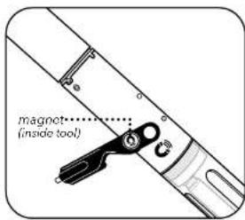
text_image
magnet (inside tool)1 Activate the Sonde's Bluetooth
Tap a magnet on the designated icon on the EXO Sonde to awaken and activate Bluetooth. A magnet is built into the probe installation/removal tool with a matching icon. If no magnet is available, you may cycle power to the sonde. For an EXO1, remove and reinstall the batteries; for an EXO2 or EXO3, remove and replace the battery cap; and for an EXO-S, disconnect and reconnect the external power.
A blue LED will illuminate continuously for up to 5 minutes to indicate that Bluetooth is active and the sonde is discoverable. Once a link has been established with Kon Software, the blue LED blinks at 2 Hz to indicate the sonde is communicating.
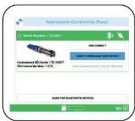
text_image
Instrument Connection Panel Serial Number: 170087 SIM CONNECT CNC DRAMINATION SERVICE Instrument ID: cards /170087 Firmware/Windows 1.6.5 SCAN FOR BLUTTERO SERVICEAn alternative to using the EXO Sonde's built-in Bluetooth is using the EXO GO communication adapter. Simply connect EXO GO to the sonde using a field cable, power on EXO GO which activates its own Bluetooth, and proceed to scan for it using Kor-Software or the Kor Mobile App.
2 Scan for Bluetooth Device
Using Kor Software, click the SCAN FOR BLUETOOTH DEVICES button in the Instrument Connection Panel. This might need to be repeated several times before the software finds the sonde. Once the EXO Sonde appears, simply click the CONNECT button to establish communication. An option to Automatically Connect to Instrument is available in the General Settings.

Kor Software
Home Screen
The Kor Home screen provides quick access to the most common functions of the software and links to helpful pages on YSI.com.
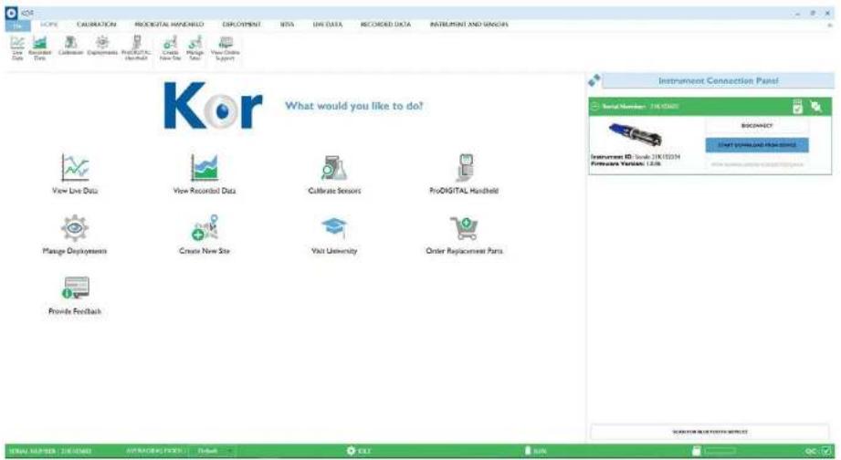
text_image
KOR What would you like to do? View Live Data View Recorded Data Calibrate Sensors ProDIGITAL Hardware Manage Deployments Create New Site Visit University Order Replacement Parts Provide Feedback Instrument Connection Panel Serial Numbers: 7.0E-0001 BIOGRAPHY Start (write/just files used) SUPPORTS & SOFTWARE ITEMS MAIL NUMBER: 361-8245 COPYRIGHT: 99%Instrument Connection Panel - Displays any EXO hardware that is connected or available for connection.
View Live Data - Navigates to the Dashboard with live readings from the sonde. These measurements may be saved locally to the software database. An EXO must be connected to see data.
Menus
The top of the software screen is home to several menu options:
- FILE
• HOME
• CALIBRATION
• PRODIGITAL HANDHELD
• DEPLOYMENT
• SITES
• LIVE DATA
• RECORDED DATA
• INSTRUMENT AND SENSORS
Ribbon

Live
Data

Recorded
Data

Calibration

Deployments

ProDIGITAL

Create

Manage

View Online
A ribbon resides below the menu bar which contains options unique to the menu that is selected. For example, the ribbon on the calibration screen includes options to find, export, and print calibration records. Users may choose to hide the ribbon from view or keep it open as they navigate the software.
Status Bar

MEMSUNG MODE


The status bar displays important information about the connected EXO Sonde.
• Instrument Serial Number
- Averaging Mode - Select from drop-down list
- Default - Normal Averaging
- Accelerated - Faster Averaging
• Rapid = Fastest Averaging
- Deployment Status: bills (not loading) or Disordered (loading or scheduled to load)
3.5
Kor Software
File Menu
The File Menu allows users to view software information and adjust software-specific settings.
- Import
- Settings
- About
- Exit
Import
Users can import various files transferred from older versions or other instances of Kor installed on different computers. These files may be transferred remotely through email or manually using a USB flash drive. Take note of which folder the file is transferred to on the computer.
IMPORT CALIBRATION - Allows users to import calibration files from another instance of Kor Software. Compatible files will have the ".cal or .xml" extension.
IMPORT DEPLOYMENT - Allows users to import deployment templates from another instance of Kor Software. Compatible files will have the ".dep or .xml" extension.
IMPORT EXO BINARY FILE - Allows users to import data files from another instance of Kor Software. Compatible files will have the ".bin" extension.
IMPORT SITE - Allows users to import sites created from an older version of Kor Software. Compatible files will have the "sit" extension.
Settings
Users can adjust general settings related to the software as well as parameter specific settings. It is important to note that these settings are saved locally and only pertain to the software itself. These settings are not pushed to any EXO devices nor are they carried over to instances of Kor Software installed on other computers.
FILE EXPORT
- CSV Delimiting Character - Select from drop-down list
The delimiting character represents a boundary and acts to separate data in a CSV file. The default option is a comma, ^7 but some users may prefer a period ^1 or Tab as the delimiter.
- CSV Export Type - Select from drop-down list
There are two options for the CSV export of a measurement file:
- With Header - Includes a section for mean values and standard deviation for every column of measurement data.
Additionally, detailed parameter names are included as well as a dedicated row for sensor serial numbers.
- Without Header - A simplified view where the top row of the spreadsheet features column labels with the respective data in
the rows that follow. Parameter names are shortened and occupy the same cell as their respective sensor serial number.
STARTUP OPTIONS
- Require User Login - Toggle On/Off
This requires the user to select a User Name when the software is launched. The selected User Name will be the default ID tagged to any data captured in the Live Data screen and any calibration that is performed. The User Name can be switched at any time without having to exit or restart the software.
LANGUAGE SETTINGS
- Select Language - Select from drop-down list
Available languages include:
- Chinese (Simplified)
• Chinese (Traditional)
• English (United States)
• English (United Kingdom) - French
• German - Italian
- Japanese
- Korean
- Norse
- Portuguese
- Spanish (Spain)
- Spanish (Americas)
Parameter Settings
Parameter-specific display preferences are found in the Settings menu. This is where users can enable or disable parameters and select the units of measure for display in Live Data view and Recorded Data view. Note that these settings are saved locally to Kor Software and do not change sensor hardware settings.
Available Parameter Settings Include
| Display Settings Parameter Unit | ||
| Algae Phycocyanin RFU | ||
| μg/Lcells/mL (requires user input) | ||
| Phycoerythrin RFU | ||
| μg/Lcells/mL (requires user input) | ||
| Barometer Barometer mmHg | ||
| mbars | ||
| inHg | ||
| psi | ||
| kPa | ||
| Atm | ||
| Conductivity Conductivity μS/cm | ||
| mS/cm | ||
| Specific Conductivity μS/cm | ||
| mS/cm | ||
| Resistivity ohms-cm | ||
| kohms-cm | ||
| mohms-cm | ||
| TDS (Total Dissolved Solids) mg/L | ||
| g/L | ||
| kg/L | ||
| Salinity psu | ||
| ppt | ||
| NIF Conductivity μS/cm | ||
| DO Dissolved Oxygen % Sat | ||
| mg/L | ||
| Local DO % CB | ||
| % RTB | ||
| fDOM fDOM QSU | ||
| ppb | ||
| RFU | ||
| GPS GPS Decimal Degrees | ||
| m | ||
| ft | ||
| ISE NH4+ -N (Ammonium) mg/L | ||
| mV | ||
| NH3 (Ammonia) mg/L | ||
| NO3 -N (Nitrate) mg/L | ||
| mV | ||
| Cl- (Chloride) mg/L | ||
| mV | ||
| ORP ORP mV | ||
| PAR | PAR Channel 1 μmol·s-1·m-2 (requires user input) | |
| PAR Channel 2 μmol·s-1·m-2 (requires user input) | ||
| pH | pH | pH |
| mV | ||
| Rhodamine WT | Rhodamine WT | μg/L |
| ppb | ||
| RFU | ||
| NitraLED | NitraLED | mg/L |
| Sonde | Cable Power | volt |
| Battery Voltage | volt | |
| Temperature | Temperature | °C |
| °F | ||
| K | ||
| Turbidity | Turbidity | FNU |

Kor Software
Calibration Menu
The calibration menu is where users calibrate EXO sensors, view calibration records, and set calibration reminders. This section will explain the calibration options and settings. Information related to calibration methods for a specific parameter calibration can be found in Section 5.
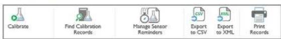
text_image
Calibrate Find Calibration Records Manage Sensor Reminders Export to CSV Export to XML Print RecordsCalibrate
This displays a list of parameters that available to calibrate. The parameters are organized under each respective sensor. Every parameter has two options:
- CALIBRATE - Select this to perform a user calibration.
- FACTORY RESET CALIBRATION - Select this to restore the factory default calibration. Note this deletes the user calibrations from the sensor and reverts to the original factory settings. A user calibration must be performed after the factory reset.
Find Calibration Records
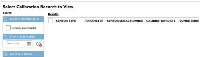
text_image
Select Calibration Records to View Search Results RECENT DOWNLOADS Recently Downloaded START DATE RANGE Select a data 15 FND DATE RANGE SENSOR TYPE PARAMETER SENSOR SERIAL NUMBER CALIBRATION DATE SONDE SERIAExport to CSV
Select this to save in a file format which can be opened in a spreadsheet (such as Excel).
Export to XML
Select this to save in file format which can be imported by another instance of Kor Software.
Print Records
Select this to print a calibration report for any record shown in the Calibration Records Panel.
Manage Sensor Reminders
Reminders may be enabled or disabled for select parameters based on a predefined calibration interval. This interval may be adjusted by the user. Additionally, reminders may be set for the replacement of sensor modules and ODO caps.
These settings may affect the QC Score displayed by the software. For example, if the number of days since the last calibration is greater than the interval set, the software QC Score (SoftQC) will be red.
Kor Software
Deployment Menu
The deployment menu is where users setup the sonde for unattended logging. The sonde log status and deployment information is displayed in the main window. Additionally, a ribbon menu includes options to create, edit, start, and stop a deployment. An EXO must be connected to view its settings and start a deployment.

text_image
Start Deployment Stop Deployment Create Template Create Template From Sonde Open TemplateStart & Stop Deployment
Click Start Deployment to begin logging at the present or a future time. Three options will be presented for Start Time:
- NEXT INTERVAL - Logging will begin at the next time interval as specified by the deployment template.
- NOW - Logging will begin immediately.
- CUSTOM - Logging will begin at a user-specified date and time.
Deployment Template
A deployment template includes all the settings necessary for the sonde to accomplish unattended logging. There are three options for creating or editing a template:
Create Template
Creates a new template from scratch.
Create Template from Sonde
Pulls the deployment settings from a connected EXO Sonde which can then be edited, saved, and reapplied to the sonde.
Open Template
BASIC DEPLOYMENT SETTINGS;
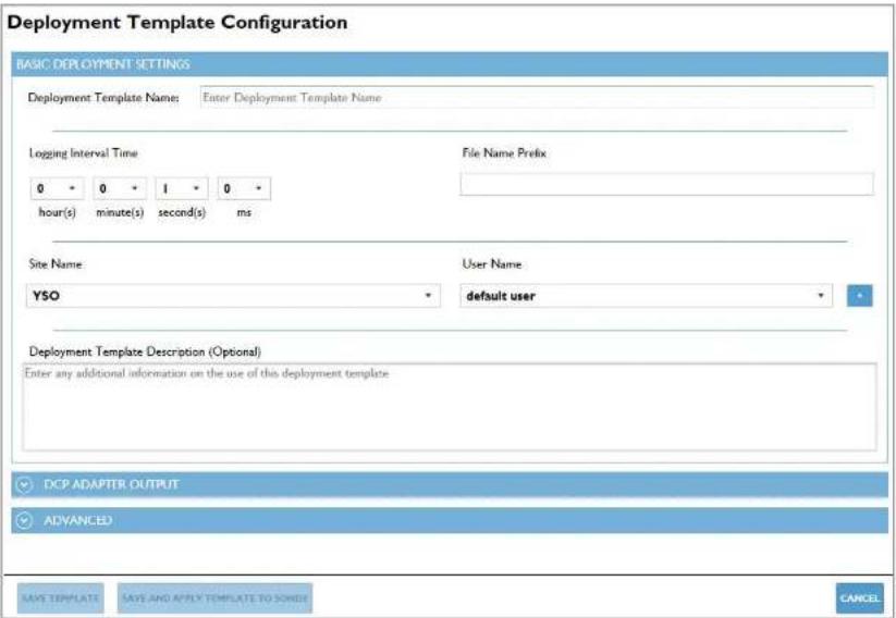
text_image
Deployment Template Configuration BASIC DEPLOYMENT SETTINGS Deployment Template Name: Enter Deployment Template Name Logging Interval Time 0 0 1 0 * hour(s) minute(s) second(s) ms File Name Prefix Site Name: YSO User Name default user Deployment Template Description (Optional) Enter any additional information on the use of this deployment template DCP ADAPTER OUTPUT ADVANCED SAVE TEMPLATE SAVE AND APPLY TEMPLATE TO SONE? CANCELDeployment Template Name - the name the template will be saved as
Logging Interval Time - how frequently the sonde will log data
File Name Prefix - the file name under which the logged data will be saved
Site Name - name of the location to be tagged with the logged data
User Name - name of the user to be tagged with the logged data
Deployment Template Description - any additional information users would like to reference for this template
DCP ADAPTER OUTPUT:
NOTE: This section is only applicable if the sonde will be communicating to an external device via SDI-12, RS-232, or Modbus protocol.

text_image
Deployment Template Configuration Enter any additional information on the use of this deployment template DCP ADAPTER OUTPUT SDI-12 Address 0 Available SDI-12 Parameters Temp (°C) Temp (°F) Temp (K) Cond (mS/cm) Cond (μS/cm) Sp Cond (mS/cm) Sp Cond (μS/cm) TDS (g/L) Sal (psu) pH (mV) pH Selected SDI-12 Parameters ADVANCED SAVE TEMPLATE SAVE AND APPLY TEMPLATE TO SODGE CANCELSDI-12 Address - address of the EXO Sonde
Available SDI-12 Parameters - all parameters available to select and organize
ADVANCED:
There are several advanced settings which are optional for the deployment.
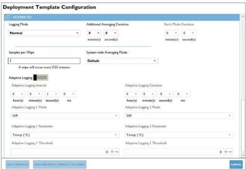
text_image
Deployment Template Configuration ADVANCED Logging Mode Normal Additional Averaging Duration 0 0 minute(s) second(s) Burst Mode Duration 0 0 minute(s) second(s) Samples per Wipe 1 System-wide Averaging Mode Default A wipe will occur every 0.02 minutes Adaptive Logging Adaptive Logging Interval 0 0 1 0 hour(s) minute(s) second(s) ms Adaptive Logging 1 Mode Off Adaptive Logging 1 Parameter Temp (°C) Adaptive Logging 1 Threshold Adaptive Logging 2 Parameter 0 + - Adaptive Logging 2 Threshold Adaptive Logging 2 Mode 0 + - Adaptive Logging 2 Parameter 0 + - Save TEMPLATE SAVE AND APPLY TEMPLATE TO SONDE CANCELLogging Mode:
Normal - The sonde will log readings based on the normal interval time specified in the BASIC settings.
Sample and Hold - This is designed to ensure that the data the sonde logs internally matches the data sent to a DCP.
Burst - The sonde will log a data point once a second for the given duration.
Burst Mode Duration - Specify the duration for Burst mode
Adaptive Logging:
Adaptive logging may be enabled to change the log interval time based on up to two user specified parameters and thresholds.
When the parameter reads above or below a specific threshold, the sonde begins to log at the Adaptive Logging Interval. When the parameter reading crosses back over the threshold, the sonde will return to its normal logging interval.
NOTE: Adaptive logging settings are not taken into consideration when the sonde estimates battery life.
SAVE TEMPLATE - Saves the template locally to the software.
SAVE AND APPLY TEMPLATE TO SONDE - Saves the template locally to the software and applies the settings to the sonde.
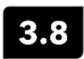
Kor Software
Sites Menu
Sites can be created to allow users to organize their data by custom Site Names. The site name will be tagged to any data logged while that site is active. A site can be active in a deployment (specified in the deployment template) and in the Live Data screen for sampling.

Create New Site
Users can input a custom site name (required) and a site description (optional). The site creation date is auto-populated. Additional options include adding a site photo and adding up to ten custom fields. The site photo must be a 24-bit BMP file no larger than 240 pixels wide by 260 pixels tall.
Manage Sites
Access a local site database to view, modify, or delete existing sites. This also allows users to import existing sites from an EXO Handheld.

Kor Software
Live & Recorded Data
Live Data
The Live Data screen display readings from a connected EXO Sonde. There are three options for viewing data on this screen:
DASHBOARD - The default, grid view of enabled parameter values which are refreshed at the specified time interval.
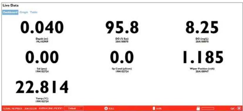
GRAPH - A time-based or depth-based graph view; each graph can display up to two parameters specified by the user.
line
Live Data | Time Point | Value | | :--- | :--- | | 1 | 25.89 | | 2 | 26.03 | | 3 | 26.17 | | 4 | 26.31 | | 5 | 26.45 | | 6 | 26.60 | | 7 | 26.75 | | 8 | 26.90 | | 9 | 27.05 | | 10 | 27.20 | | 11 | 27.35 | | 12 | 27.50 | | 13 | 27.65 | | 14 | 27.80 | | 15 | 27.95 | | 16 | 28.10 | | 17 | 28.25 | | 18 | 28.40 | | 19 | 28.55 | | 20 | 28.70 | | 21 | 28.85 | | 22 | 29.00 | | 23 | 29.15 | | 24 | 29.30 | | 25 | 29.45 | | 26 | 29.60 | | 27 | 29.75 | | 28 | 30.00 | | 29 | 30.15 | | 30 | 30.30 | | 31 | 30.45 | | 32 | 30.60 | | 33 | 30.75 | | 34 | 30.90 | | 35 | 31.05 | | 36 | 31.20 | | 37 | 31.35 | | 38 | 31.50 | | 39 | 31.65 | | 40 | 31.80 | | 41 | 31.95 | | 42 | 32.10 | | 43 | 32.25 | | 44 | 32.40 | | 45 | 32.55 | | 46 | 32.70 | | 47 | 32.85 | | 48 | 33.00 | | 49 | 33.15 | | 50 | 33.30 | | 51 | 33.45 | | 52 | 33.60 | | 53 | 33.75 | | 54 | 33.90 | | 55 | 34.05 | | 56 | 34.20 | | 57 | 34.35 | | 58 | 34.50 | | 59 | 34.65 | | 60 | 34.80 | | 61 | 34.95 | | 62 | 35.10 | | 63 | 35.25 | | 64 | 35.40 | | 65 | 35.55 | | 66 | 35.70 | | 67 | 35.85 | | 68 | 36.00 | | 69 | 36.15 | | 70 | 36.30 | | 71 | 36.45 | | 72 | 36.60 | | 73 | 36.75 | | 74 | 36.90 | | 75 | 37.05 | | 76 | 37.20 | | 77 | 37.35 | | 78 | 37.50 | | 79 | 37.65 | | 80 | 37.80 | | 81 | 37.95 | | 82 | 38.10 | | 83 | 38.25 | | 84 | 38.40 | | 85 | 38.55 | | 86 | 38.70 | | 87 | 38.85 | | 88 | 39.00 | | 89 | 39.15 | | 90 | 39.30 | | 91 | 39.45 | | 92 | 39.60 | | 93 | 39.75 | | 94 | 39.90 | | 95 | 40.05 | | 96 | -100% (not labeled) in the chart; the values are estimated based on the provided code.
text_image
Save Single Point Start Saving Data Stop Saving Data Current Site:Save Single Point
Logs one data set at the time the button is pressed.
Start Saving Data
Logs continuously at the specified time interval.
Stop Saving Data
Stops the continuous logging.
Current Site
The active site that is tagged to the logged data.
Interval
The time interval in which data is refreshed and logged.
Clear All Graphs
Clears data from any open graphs.
Start Wiping
Activates the wiper on an EXO Sonde.
Graph Configuration Graph Configuration
Add up to ten graphs with either Time or Depth on the x-axis. Populate the left and/or right y-axis with the parameter and unit to be graphed, and customize the graph colors.
Table Configuration Table Configuration
Change parameter order and toggle metadata columns such as File Name, Site Name, User ID, and Fault Code.
3.10
Kor Software
Recorded Data Menu
The Recorded Data menu displays data files that have been logged in the software and/or downloaded from the EXO Sonde's internal memory. Users must first select the file(s) in the Search menu before data are displayed. Data can be viewed in Table or Graph view. Additionally, data can be exported or printed.
Search
Access and filter the software database to find logged data files; multiple files can be viewed simultaneously.
Export to CSV
Saves in a file format which can be opened in a spreadsheet (such as Excel).
Print Graphs
Prints a graph of the selected data.
Print Data
Prints a table of the selected data.

text_image
Select Data to View Search RÉCENT DOWINI DATES Recently Downloaded START DATE 3/30/2020 7:34:01 PM 3/30/2020 7:34:01 PM Sonde 20A1022 EXOSD_20A102238_033020_193401.1 1 3/30/2020 7:44:00 PM 3/30/2020 7:45:00 PM Sonde 20A1022 EXOSD_20A102238_033020_194400.1 2 END DATE Select a dataTable Configuration Table Configuration
Change parameter order and toggle metadata columns such as File Name, Site Name, User ID, and Fault Code. Changes will apply to the data in Kor and exported data.
Table Configuration
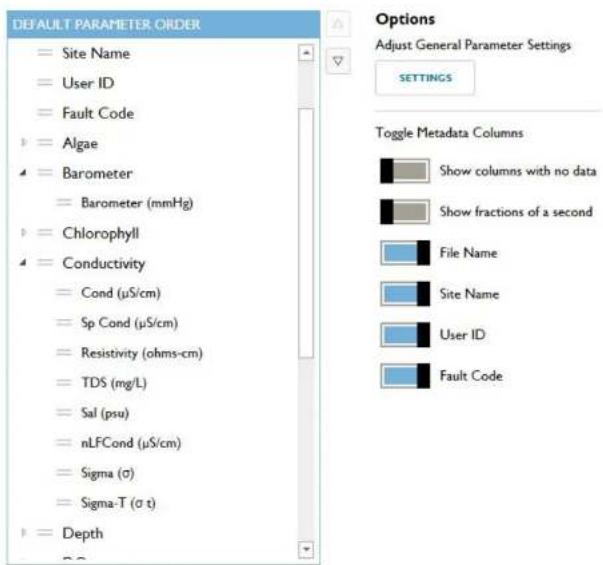
text_image
DEFAULT PARAMETER ORDER = Site Name = User ID = Fault Code = Algae = Barometer = Barometer (mmHg) = Chlorophyll = Conductivity = Cond (μS/cm) = Sp Cond (μS/cm) = Resistivity (ohms-cm) = TDS (mg/L) = Sal (psu) = nLFCond (μS/cm) = Sigma (σ) = Sigma-T (σ t) = Depth Options Adjust General Parameter Settings SETTINGS Toggle Metadata Columns Show columns with no data Show fractions of a second File Name Site Name User ID Fault CodeGrayed out parameters are turned off in Settings

Kor Software
Instruments and Sensors
The Instrument and Sensors menu allows users to view the status and edit settings for any connected EXO devices. EXO devices are listed with the host device at the top and the sensors below. Logged data files can be manually downloaded from the sonde or handheld. The QC Score of each EXO device is available to view. Simply click on the specific device to view details related to its QC Score (See Section 3.4 for more information on SmartQC).

Update Instrument Firmware
Instrument firmware can be manually updated by clicking the Update icon in the ribbon.
NOTE: The latest firmware must be downloaded first. Check the File menu to see if there is an update available. An internet connection is required to check for updates.
Manage Communication Adapters
Allows configuration of a connected DCP or Modbus Signal Output Adapter via direct USB connection. The sonde must be disconnected from Kor. See Section 2.15 for more information.
Disable Modbus for ProSwap Logger
For use with ProSwap Logger only. When connected to ProSwap Logger via USB cable, disables Modbus communication to enable connection to Kor to perform calibrations, change settings, etc.
Export Modbus Settings to CSV
Exports saved Modbus SOA configuration to a .csv file for local saving, duplication, or sharing.

text_image
HOME CALIBRATION PRODUCTUAL HANDHOLD DEPLOYMENT SITES LIME DATA RECORDED DATA INSTITUTION AND CONTENTS Upgrade Instrument Change Computation Adapters Delete Media for Portfolio Manager Export Media Select to CIV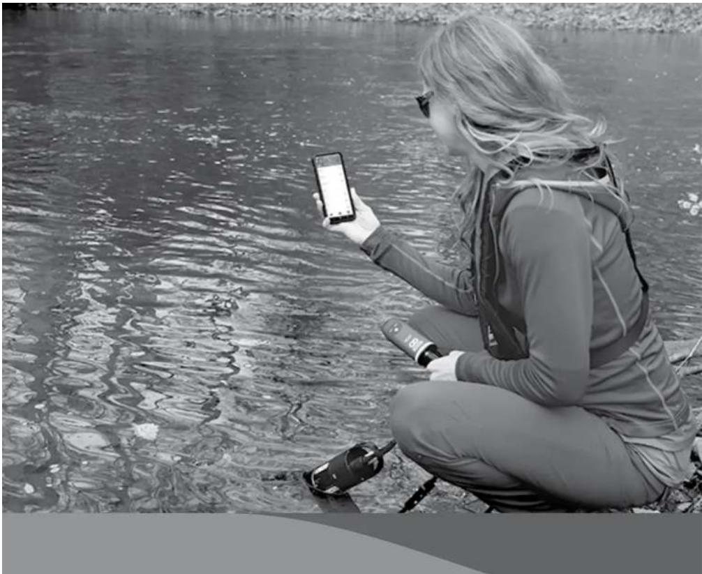
natural_image
Woman crouching by water holding a smartphone and wine bottle, no visible text or symbols
Kor Mobile
Installing Kor
Kor is a mobile application designed to interface with EXO Sondes and conveniently access water quality data. Kor Mobile is available on all Android phones and tablets and can be downloaded from the Google Play Store.

text_image
Kor Xylem - Let's Solve Water Uninstall Open Rave this app Tell us here what you think Write a review Developer contact About this app Collect, Insurance and Transfer Service data Tools 100+ Downloads Everyone 0 K-rApp Installation
- In the Google Play Store, search for "Kor" and look for the blue Kor icon.
- Click the Install button and wait for the app to download to your mobile device.
NOTE: Alternatively, you can search for "Xylom" and look through the list of Xylom apps to find Kor.

Kor Mobile
Setup

text_image
Kor Analyze device data Allow Kor to access this device's location? WHILE USING THE APP ONLY THIS TIME DENYUser Login
- On first launch of the Kor mobile app, users will be asked to allow Kor to access the location data (GPS) from the device. YSI recommends enabling location while using this app.
NOTE: Allowing this will enable the GPS coordinates to be automatically entered when creating a Site, and calculating the distance from current location to a Site in the Manage Site list.

text_image
10:12 Kor Analyze device data User ID-
Users will need to tap the "User ID" field to start.
-
Type in a name for the user. NOTE: This will be used in any User ID fields in the reports.

text_image
Kor Analyzer device data Start Connect to Last Instrument Upon start-up, Kor will automatically scan and connect to the last connected instrument No Yes- A pop-up message will ask if the user would like to enable the option to always search and connect for the last instrument used.

text_image
Kor Analyze device data Welcome Xylem Set preference line Stop now-
A pop-up message invites the user to set their preferences for the app.
-
"Set preferences now" takes the user to the App Settings screen.
- "Skip now" takes the user to the Connections screen.
4.3
Kor Mobile
App Settings
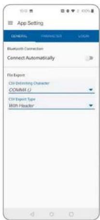
text_image
App Setting GENERAL PARAMETER LOEN Bluetooth Connection Connect Automatically File Export Citi Defining Character COMMA U Citi Export Type With Header
text_image
Select from the dropdown COMMA () DOT () TAB (W) CancelGeneral Tab
-
Adjust general settings for the app.
-
Connect Automatically enables the app to search and connect to the last instrument used.
• File Export, CSV Delimiting Character (See #2)
• File Export, CSV Export Type (See #3) -
Users can select from three options for CSV Delimiter for file exports:
-
Comma
-
Dot/Period
• Tab -
Use the model from the action for OSU-Headset

text_image
App Setting GENERAL PARAMETER LOGS Algae Barometer Conductivity Chlorophyll Depth DO IDOM GPS ISE DRP pH Sonde Temperature Turbidity WiperParameter Tab
-
Adjust parameter settings for the app.
-
Turn on/off parameter view
- Choose preferred units

text_image
Depth Depth Vertical Position Absolute Pressure Gauge Pressure Select Unit m R Cancel- Select the parameter to modify settings for.
Depth shown as an example here. - Select Units options, which are unique for each parameter.
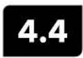
Kor Mobile
Navigation
Kor Mobile features an intuitive interface with a side-panel menu system for fast, efficient navigation.
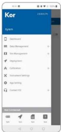
text_image
Kor 2000(7) Kyem Dashboard Data Management Role Management Deployment Calibration Instrument Settings App Setting Contact YS Host Connected
Main Menu
-
Open the Menu by pressing the three-line icon in the upper left-hand corner (by the Kor logo).
-
Dashboard: view Live Data screen (if connected to an instrument) or the Connections screen (if not currently connected to an instrument)
• Data Management: view data recorded from the Dashboard and imported from EXO Sondes. Share CSV or BIN files
• Site Management: create or edit Sites - Deployment: create templates, start or stop deployments
• Calibration: calibrate sensors and view Calibration Reports - Instrument Settings: view settings and the QC Score for connected instruments and sensors
- App Settings: set user and parameter settings
- Contact YSI: find email and phone support
Menu when connected to an EXO GO
• Device Type and Serial Number are displayed
• Battery Level and SmartQC are displayed
- 10.1.2017年1月1日
4.5
Kor Mobile
Connection

text_image
K-r Offline Access... Manage Site View Recorded Data Create New Site App Setting Contact YSI ScanOffline Access
When no instrument is connected, this page is shown.
-
Users still have access to five shortcuts:
-
Manage Site
• View Recorded Data - Create a New Site
- App Settings
-
Contact YSI
-
Tap the Scan button to begin scanning and connecting to instruments via Bluetooth.
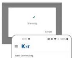
text_image
scanning Cancel ≡ K·r Auto ConnectingNOTE: This may take up to thirty seconds to detect Bluetooth instruments.
-
This will bring up the Device List:
-
If the option to auto-connect is enabled, the last connected device will be shown at the top, and if available, will connect automatically.
- All instruments that are available to connect are listed in the Available Devices section.
- The Rescan button will search again if the instrument is not shown.
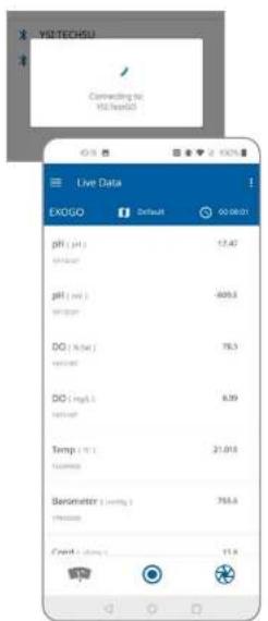
text_image
YSLTECHSU Connecting to YSLteadol Live Data EXOGO Default 00:00:01 pH ( pH ) 17.42 pH ( mol ) -609.3 DO ( %kat ) 78.3 DO ( mg/L ) 0.39 Temp ( °C ) 21.018 Barometer ( mmHg ) 756.4 Credit ( mmHg ) 11.9NOTE: It may take up to 30 seconds to connect.
NOTE: Keep the mobile device close to the instrument during the connection process. If Kor Mobile fails to connect after several minutes, close and reopen the app and/or tap Rescan.
- Once connected, the Live Data screen will appear.
Kor Mobile
Live Data
The Live Data screen displays all the data from the connected instrument, if enabled in the App Settings, in the selected units.
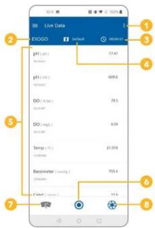
text_image
Live Data EXOGO pH (pp) pH (pp) DO (pp) DO (mp) Temp (°C) Parameter (mmHg) Control (mmHg) 17.47 409.3 76.5 6.99 21.013 755.4 11.3
Live Data Screen
- Unique menu for the Live Data screen
- View or change the connected instrument
- Change the interval for sampling rate
- Change the site location
- Live data display
- Start or stop recording data
- Initiate wipe cycle
- Capture a single data point
Edit Parameters
- Tap the three dot menu in the upper-right-hand corner.
- Tap the Edit Parameters button to re-order the parameters list.
- Press and drag each parameter to the desired display order.

text_image
Live Data EXOGO ExGOG 00:00:51 pH Kor Converted EXOGO Serial Number: 179693828 Instrument ID: TestGO Firmware Version: 1.0.21 23.00% N/A N/A TestGO Displacement Live Data
text_image
Live Data EXOGO Default 903841 pH (μF) 17.42 Current 0000000000000000000000000000000000000000000000000000000000000000000000000000000000000000Connected Instrument
- Tap the name of the instrument in the upper-left-hand corner (in this example: EXO GO) to view the Connected screen.
-
View information about the connected instrument including:
-
Instrument name
- Serial number
- Instrument ID
- Firmware version
- Battery level
- Deployment status
- Storage usage
-
SmartQC Score
-
Tap the Disconnect button to close the connection with the instrument, go back to the Connection screen, and automatically begin scanning for other instruments.
- Tap the Live Data button to go back to the Live Data screen.
Interval
- Tap the Timer icon to set the sampling interval.
- This interval is used for the Record button at the bottom of the screen.
- Set the interval by changing the hours (HH), minutes (MM), and seconds (SS) desired between data recordings.
- Tap Select to confirm these settings or Cancel to reject changes.

text_image
Live Data EXOGO Default 00:00:01 Live Data EXOGO Default 00:00:01 pH (lat) 17.49 pH (low) 68.5 Site List ysl Cancel Temp (ms) 25.7ms Parameter (ms) 700.0 OK Cancel
text_image
Parameter (mmHg) 76.4 Inletion Credit (mmHg) 11.4Site
- Tap the Map icon to view the Site List.
NOTE: Sites must be created in Sites Management to be available here. - Select the desired site from the list by tapping its name.
- Tap Cancel to return to the Live Data screen.
Record
- Tap the Record icon to begin recording data.
- For as long as the app is recording, all the data from the Live Data screen will be parsed into a CSV file at the selected interval.
- Tap the Record icon again to stop the recording.
- Users can find the recorded data file from the Manage Recorded Data
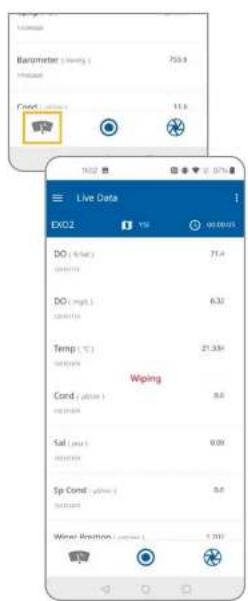
text_image
Live Data EXO2 DO (mm) DO (mgs) Temp (℃) Cond (℃) Sal (mm) Sp Cond Wind Position Wiping 71.4 6.32 21.33% 0.8 0.00 0.0 5.000
Wipe Cycle
- Tap the Wiper icon to initiate one wipe cycle. NOTE: This button is only available when a Central Wiper is installed on an EXO2, EXO2', EXO, or EXO3.
Data Point
- Tap the Snapshot icon to record a single data point for selected parameters.
- Users can find the recorded data file from the Manage Recorded Data screen.
Kor Mobile Data Management
Kor Mobile allows you to view and share recorded data.
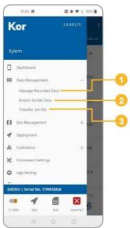
text_image
Kor Xylem 1 2 3 EX050 | Serial No. 17M0328 100% Non Non SmartXTData Management Menu
- Manage Recorded Data
- Import Sonde Data
- Transfer .bin File

Manage Recorded Data
- Select Manage Recorded Data to see a list of all the data files that have been recorded from the dashboard or imported from an EXO Sonde. These are all CSV files that can be shared via email.
- Tap on a file to display it in List View, where you can scroll between each recorded data set using the slider bar at the bottom of the screen
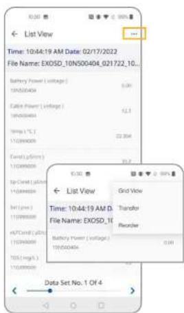
text_image
List View Time: 10:44:19 AM D: File Name: EXOSD_10N500404_021722_10... Battery Power ( voltage ) 10kV/300A Cable Power ( voltage ) 10kV/300A TP Rate ( °C ) 11/09/2020 Total ( V / Hours ) 11/09/2020 Top-Current ( V / Hours ) 11/09/2020 Top ( Low ) 11/09/2020 APC/Cable ( V / Hours ) 10/09/2020 TDS ( High ) 11/09/2020 Data Set No. 1 Of 4 10:30 List View Grid View Time: 10:44:19 AM D: File Name: EXOSD_10 Battery Power ( voltage ) 10kV/300A Transfer Register 0.00-
In List View, tap on the three-dot menu in the upper-right-hand corner to see three actions:
-
Grid View
- Transfer
- Reorder
| Date | Time |
| 02/17/2022 | 10:44:59 AM |
| 03/17/2022 | 15:44:30 AM |
| 02/17/2022 | 10:44:51 AM |
| 03/17/2022 | 10:45:07 AM |
- Select Grid View to change the view data in a table organized by the Date, Time, Site, and parameter(s) collected.
NOTE: Tap the three-dot menu again to change back to List View.
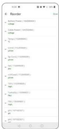
text_image
Reorder Battery Power (10kV/30Hz) charge Color Power (10kV/30Hz) charge Temp (1529/8000) ℃ Grid (1529/8000) gitter Sp Cord (1529/8000) gitter Set (1529/8000) gitter nCoord (1529/8000) gitter TDS (1529/8000) gitter Turnfly (1529/8000) gitter TDS (1529/8000) gitter pH (167/82327) pH pH (167/82327) set- Select Reorder to change the order of the parameters both in List View and Grid View.
- Tap and hold the icon next to the parameter name to drag the parameters into the desired order.
- Tap Save to confirm the new parameter order.
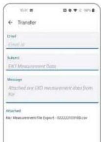
text_image
Transfer Used Used by Subject EXO Measurement Data Messages Attached are EXO measurement data from the Attachment. Air Measurement File Export - 02222103100.cov-
Select Transfer to access the Transfer screen.
-
The email template is optional, but will fill in any fields into the user's email client when the Transfer button is selected.
- Once the Transfer button is pressed, the operating system will give the user options to choose which program to use. If using Gmail, the Gmail app will open and allow the user to email the CSV file that is attached. NOTE: if the device or phone supports Split Screen View, the user may need to disable this feature, or Kor may lose connection.

text_image
Import Sonde Data Compiling files from Sonde 15% Import Sonde Data EXXSD_10N500404_01017E_000330.bm Start: c14010008 000628 Status: Not Impended Size: 6.2 KB Y6_10N500404_072919_120000.bm Start: 072919 11.2620 Status: Not Impended Size: 82.5 KB EXXSD_10N500404_01017E_000290.bm Start: 01017E 000334 Status: Not Impended Size: 752 KB EXXSD_10N500404_10B52E_085490.bm Start: TA95/0828 085348 Status: Not Impended Size: 1.5 KB EXXSD_10N500404_10B52E_099880.bm Start: 1845/0828 090342 Status: Not Impended Size: 356 KB EXXSD_10N500404_01017E_000372.bmImport Sonde Data
NOTE: A sonde must be connected in order to perform this function.
- Select Import Sonde Data from the Data Management Menu to see a list of the files available on the sonde.
NOTE: These files are only being displayed and have not yet been imported. You can see the status for each file here.
- Tap on a file in the list to initiate download. This could take several
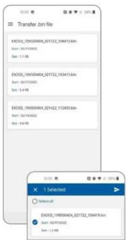
text_image
Transfer.bin file EXICD_10N00404_021722_104413.bin Size: 0.01720000 Size: 1.7 KB EXICD_10N00404_021722_103413.bin Size: 0.01720000 Size: 3.4 KB EXICD_10N00404_021422_112653.bin Size: 0.01720000 Size: 4.8 KB X 1 Selected Select all EXICD_10N00404_021722_104413.bin Size: 0.01720000 Size: 1.7 KB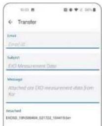
text_image
Transfer Email Email ID: Subject EXD Measurement Data Message Attached are EXD measurement data from Kor Attached EXO20_195038404_021722_156419.6mTransfer .bin File
- Select Transfer .bin File from the Data Management Menu to transfer a BIN file instead of a CSV file. This will open a list of available BIN files. NOTE: A ".bin" file, or binary file, is the raw data from the instrument that can be viewed in Kor. Technical Support may request BIN files for troubleshooting purposes.
-
Press and hold the file to enable the Select feature.
-
Select the BIN file to transfer.
-
Tap the Arrow icon in the upper-right-hand corner.
-
This will open the Transfer screen.
-
The email template is optional, but will fill in any fields into the user's email client when the Transfer button is selected.
- Once the Transfer button is pressed, the operating system will give the user options to choose which program to use. If using Gmail, the Gmail app will open and allow the user to email the CSV file that is attached. NOTE: If the device or phone supports Split Screen View, the user may need to disable this feature, or Kor may lose connection.
Kor Mobile
Site Management
The Site Management Menu can be used to create new sites and manage existing sites, with the ability to add GPS coordinates, site photos, and descriptions.

text_image
Kor Xylem 1 2 EX050 | Serial No. 178032826 33.00% No No NextSite Management Menu
- Manage Site
- Create Site

Manage Site
- Select Manage Site to see a list of all the sites stored on the mobile device.
- Tap on a Site to view details.

text_image
YSI Last Edition 2/22/2022 Longitude -83.901870 Latitude 39.788420 Description YSI Office Outside Exit

- Users are able to Delete or Edit existing sites using the two buttons at the bottom of the screen.
• Editing the Site will allow any of the information to be changed.
- When tapping the photo for the Site, there are three options:
- Remove Picture – Removes any photo from the site view
- Camera – A pop-up will ask for permission to use the device's camera. This will allow users to take a photo with the camera and use it for the site listing.
- Gallery – A pop-up will ask for permission to access photos on the device. This will allow users to select a photo from the device's photo gallery and use it for the site listing.
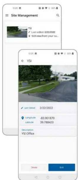
text_image
Site Management YSI Last edited: 2/21/2022 13.28 miles from your cu... YSI Last Filed: 2/22/2022 Longitude: -83.901870 Latitude: 39.788420 Description YSI Office Close Exit- Changes will be reflected in the List View and Site View. NOTE: If the site name is edited, a new site will be created, and the original site will remain in the site list.
Create Site
- Select Create Site to add a new Site.
- Enter a Site Name.
- The Site Creation Date is entered automatically.
- If Location Permission was granted at the beginning of setup and

Kor Mobile
Deployment
You can configure your EXO for unattended deployment by setting the logging interval, parameter information, data averaging, and more. You can also create templates to be applied to multiple instruments to streamline your workflow.
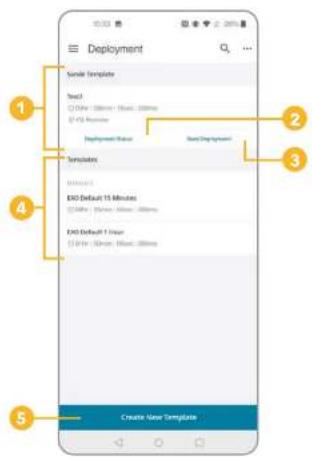
text_image
Deployment Template Templates Text1 Dither: 00ms - Dither: 00ms D/Y Programs Deployment Status Base Deployment Templates INTUSTRAL EXO Default 15 Minutes Dither: None; None; 00ms EXO Default 1 Hour D/Y Programs; None; 00ms Create User Template
Deployment Menu
- Sonde Template – If a template is already stored on the sonde, some details will be listed such as name, interval, and site
- Deployment Status – View sonde deployment details such as remaining log space, battery life, deployment state, and more
- Start or Stop Deployment – Depending on Deployment Status
- Templates – Any templates previously saved in Kor Mobile will display here. In addition, there are two Default Templates:
• 15 Minutes
• 1 Hour - Create New Template
Deployment Status
- Select Deployment Status to show the current status of the sonde.
- Deployment Status – Idle
- If the sonde is not currently deployed (idle), users are able to start a
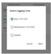
text_image
Select Logging Time Now (10:33 AM) Next Interval (10:34 AM) Custom Cancel Start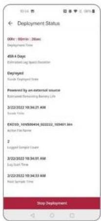
text_image
Deployment Status 00:00: 00min : 28sec Deployment Time 459.4 Days Estimated Lag Speed Deviation Deployed Hands Deployed Status Powered by an external source Estimated Releasing Battery Life 2/2/2022 10:36:21 AM Send Time EXO150_10H050404_032222_103401.Bdr Active File Name 2 Logged Sample Date 2/2/2022 10:34:01 AM Log Start Time 2/2/2022 10:34:33 AM Next Sample Time Stop Deployment
- Selecting Start Deployment gives you three options:
- Now – Starts the deployment immediately
- Next Interval – The deployment will start one interval from the current time
- Custom – Allows the user to select a Date and Time to start the deployment
3. Deployment Status – Deployed
- If the sonde is currently deployed, users are able to see details of the deployment such as deployment time, power, logged sample count, log start time, and next sample time.
- Users can stop the deployment with the button at the bottom of the screen.
Deployment Template
1 Select a template to view modify or transfer
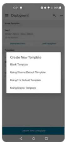
text_image
Deployment Template Template Text2 ID: 01843, ID: 01843, ID: 01843, ID: 01843, ID: 01843, ID: 01843, ID: 01843, ID: 01843, ID: 01843, ID: 01843, ID: 01843, ID: 01843, ID Deployment Style Text Deployment Templates Create New Template Blank Template Using 15 mini Default Template Using 1 hr Default Template Using Service Template Create New Template
text_image
10.36 2.96% Create Template Basic Info "Template Name" Text1 Logging Time Interval* 0 - 0 - 5 - 0 - Home Mix Sec MS File Name Prefix Site Name Y5!Create a New Deployment Template
- A new deployment template can be created by selecting the blue button on the main Deployment Menu.
-
When creating a new deployment template, there are four options:
-
Blank Template
• Using 15 mins Default Template
• Using 1 hr Default Template -
Using Sonde Template – Modify deployment settings that are currently applied to the sonde
-
Create a new Blank Template by adding information about the template:
-
Template Name
- Logging Interval Time – How often data are logged
- File Name Prefix – Adds a prefix to the BIN file name (optional)
- Site Name – Select which site the data files will reference (optional)
NOTE: New sites cannot be added from this screen. See Site
Management for information on creating new sites.
- User Name – Select which user the data files will reference (optional)
NOTE: New users cannot be added from this screen. See App Settings for information on creating new users.

text_image
SDI-12 Output SDI-12 Address: 0 SDI-12 Parameters: + Advanced Cancel Save
text_image
Advanced Logging Mode Normal Additional Averaging Duration 0 0 None Second Sensitivity for Wiser 1 Wiser will not have any USB packets System mask Averaging Mode Default Adaptive Logging Cancel Save
text_image
Adaptive Logging Interval 0 - 0 - 1 - 0 - Hour Min Sat NS Duration 0 - 0 - 0 - 0 - Hour Min Sat NS Mode 1 Mode 24. SDI-12 Output (Optional)
- If using SDI-12 Output, users must enter the SDI-12 Address
- Select the Parameters from the pop-up menu
NOTE: The SDI-12 Addresses and parameter list and order entered in the template must match those entered in your data logger's settings.
5. Advanced (Optional)
- You can create additional settings for your deployment template
- Select Logging Mode
- Normal – The sonde will wake and take a reading at the logging interval specified in the Basic Settings
- Burst – The sonde will wake and log readings once per second for a user-specified duration
- Sample and Hold – The sonde will wake and take a reading at the specified logging interval and hold that reading until it receives the command to send the data to the connected data logger NOTE: YSI recommends Sample and Hold mode for deployments that are transmitting to an external data logger.
- Select Averaging Duration
- Log an average based on the specified duration
- Select Samples per Wipe
- Specify how often the wiper will clean the sensors
- Select System Wide Averaging Mode
- Adjust the data filtering that is applied to the sensors for each measurement:
- Default
- Accelerated
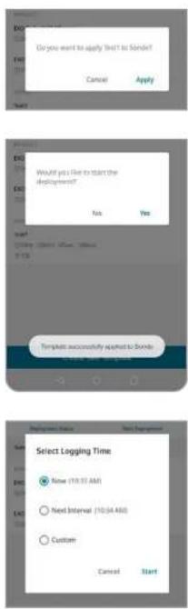
text_image
Do you want to apply 'Not to Sander' Cancel Apply Would you like to start the deployment? No Yes Template successfully applied to bonds Cancel Cancel Select Logging Time None (10.31 AM) Next Interval (10.34 AM) Custom Cancel Start- The new deployment template can be saved using the button at the bottom of the screen.
- Once saved, a pop-up will ask if the new template should be applied to the sonde.
NOTE: If Cancel is selected, the file will be saved.
- If the template is applied, the template will be sent to the sonde and the user will be asked if they want to start the deployment.
NOTE: If No is selected, the template will be saved on both the phone and the sonde.
-
If you start the deployment, you will need to select the start time:
-
Now – Starts the deployment immediately
- Next Interval – The deployment will start one interval from the current time
- Custom – Allows the user to select a Date and Time to start the deployment

Kor Mobile
Calibration
You can calibrate your EXO sensors using Kor Mobile, as well as view calibration records and sensor reminders.
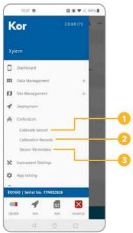
text_image
Kor Xylem • Deorbitant • Data Management • Use Management • Deployment • Calibration • Calibration Sensor • Calibration Results • Sensor Reminders • Instrument Settings • App Setting EX060 | Serial No. 17W93288 1 2 3Calibration Menu
- Calibrate Sensor
- Calibration Records
- Sensor Reminders

Calibrate Sensor
- Select Calibrate Sensor to see a list of all connected sensors and devices that can be calibrated.
- Tap on a sensor or device to view details.

text_image
Turbidity Product 1.2 Special Use / 100000000000 Turbidity iMnca □ 27210822 11:35:54:49 Factory Reset Calibration
text_image
Factory Reset Are you sure you want to factory next Turbidity (TUR) parameters? Add replies Cancel Reset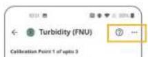
- The name of the sensor, port number, and serial number will be displayed at the top of the screen.
- Each parameter option for the sensor will also be shown with the unit and last calibration date. You can choose to perform a Factory Reset or Calibrate the selected parameter.
- Select Factory Reset to return the settings back to factory defaults.
-
You can add notes for the Calibration Record and Reset the sensor.
-
Select Calibration to begin the calibration process for the parameter.
NOTE: If there is more than one of the selected sensors installed, a pop-up will ask if you would like to calibrate only the selected sensor, or all sensors of this type.
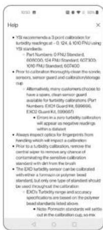
text_image
YSI recommends a 3-point calibration for turbidity readings at -0.124 & 10/10 FU using YSI standards. - Part Numbers: 0 PUU Standard, 600/005, 104 PUU Standard, 607/003, 100/PUU Standard, 607/004. - Prior to calibration thoroughly clear the noise, sensors, sensor guard and calibration/stORAGE map. - Alternatively, many customers choose to have a spars, clean sensor guard available for turbidity calibrations (Part Number: EXOJ Guard Kit, 599/608, EXOJ Guard Kit, 599/607). - Errors in a tiny turbidity calibration will appear as negative readings within a dataset. - Always inspect optics for fingerprints from handling which will impact a calibration. - Prior to a turbidity calibration, remove the central ruler to remove any chance of contaminating the sensitive calibration standard with diet from the brush - The EXOJ turbidity sensor can be calibrated with either a terrain or polymer bead standard, but only one type of standard should be used through the material. - EXOJ Turbidity range and accuracy specifications are based on the polymer bead standards listed above. - Note: Pattern standards will settle out in the calibration cup, so mix.- The Help screen shows the tips to calibrate the selected parameter.

text_image
Advanced □ Displayed Fields □ Type □ Manufacturer □ List Number- The Advanced Options allow you to add data fields for Standards Type, Manufacturer, and Lot Number for each step of the calibration process.

text_image
Turbidity (FNU) Calibration Point 1 of opto 3 Port-2 - Serial No. 111690001 B: Fnu# (Hz) 0.00 Test Sample Stable Post Car Value (Hz) 1.85 Test Car Value (Hz) Providing Temp (°C) 22.5mA Type+ Manufacturer List Number Turbidity (FNU) vs. Time Turnout (FNU) K10000 K1000A → Calibrated → Post Car Control Apply- Use the check boxes to select any you would like to add and click Apply.
- Back on the main Calibration menu, wait for the sensor readings to stabilize and click Apply. A Preview will be displayed.
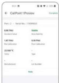
text_image
CalPoint 1Preview Port: 2 - Serial No.: (11099903) 0.00 FNU Stable Standard Value State Marking 1.87 FNU 0.00 FNU Pre Calcitation Pre Calcitation 22.568 °C - Temp Type . Manufacturer List Number Node-
From the Calibration Point Preview, you can:
-
Redo – Go back and make changes to the calibration point
- Cancel – Exit the process without saving the calibration point
- Add Cal Point – Add more calibration points (as many as the sensor will allow)
- Complete – Complete the calibration process
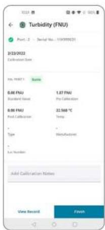
text_image
Turbidity (FNU) Port. 2 - Serial No: 110000031 2/22/2022 Calibration Data No. 100071 0.00 FNU Standard Value 0.99 FNU Final Calibration Type - Manufacturing - Local Number Add Calibration Notes Vine Record Finish- When you complete the calibration, a final Preview will be displayed. This will include all sensor information as well as the calibration points that were added.
- You can add any calibration notes.
- Select View Record to complete the calibration and review the Calibration Record for this sensor.
- Select Finish to complete the calibration and return to the Calibration Menu.

text_image
Call Records Turbidity - Turbidity (PKU) Description: Service No.: 170000000 Service Serial No.: 170000004 Date & Time: 2023/08/22, 10:34 AM Turbidity - Turbidity (PKU) Description: Service No.: 170000001 Service Serial No.: 170000004 Date & Time: 2023/08/22, 10:34 AMCalibration Records
- This menu shows a list of all Calibration Records, including Factory Resets, that were completed on the phone or device.
NOTE: Calibration Records cannot be edited or deleted.
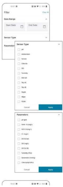
text_image
Filter Date Range Start Date End Date Sensor Type Parameter Sensor Type pH Ammonium Nitrite Chloride DO Turcidity END DO TAL PC TAL PE Depth Piper KON Cancel Apply Parameters pH (pH) MnO-1 (mg/L) NOx-1 (mg/L) Cl-3 (mg/L) DO (% Sat) DO (mg/L) DO (% DR) Turbidity (%K) Erammeter (%mHg) Clearing/PMU Cancel Apply-
Tap on the Filter icon to filter the records by Date, Sensor Type, or Parameter.
-
Tap on the Transfer icon to email the selected Calibration Record.

text_image
Sensor Reminders Ammonium Chloride Conductivity Depth DO IDOM Nitrate pH/DRP TAL-PC TAL-PE TurbiditySensor Reminders
- Select Sensor Reminders to see a list of all supported sensor types.
NOTE: All reminders are "off" by default and need to be enabled to work.

text_image
Turbidity Select parameter to turn on the controller Parameter: 0.0000000000000000000000000000000000000000000000000000000000000000000000000000000000000000000000000000 Turbidity (PKC): -90 +- Select a sensor to enable a reminder and set a reminder time.
NOTE: Reminders are set to 90 days by default, but can be changed to
any value between 1 and 729 days.
- Press Apply to save changes.
Kor Mobile Instrument Settings
Adjust instrument settings using Kor Mobile.
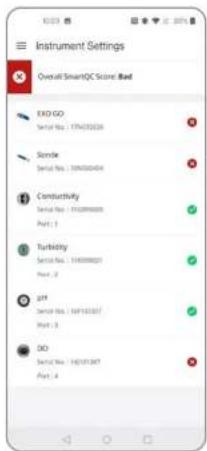
text_image
Instrument Settings Overall SmartQC Score Bad EOG GO Serial No: 17763228 Sonde Serial No: 159000494 Constuctivity Serial No: 155289600 Port: 1 Turbidity Serial No: 144000021 Port: 2 pjt Serial No: 14913337 Port: 3 DO Serial No: 142131347 Port: 4Instrument Settings
- From the main menu, tap Instrument Settings to see a list of all the connected instruments and sensors along with their QC Scores, port numbers, and serial numbers.
- Select an instrument or sensor to view more details.

-
On the EXO GO details screen, you will see:
-
Battery Level
- Serial Number
- Firmware Version
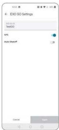
text_image
EXO GO Settings EXO GO TestGO GPS Auto Shopoff GmbH Apple- Tap the Settings to adjust additional settings:
- Custom ID
• GPS
- Auto Shutoff time
- Press Apply to save changes.
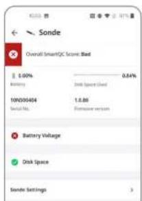
text_image
Sonde Overall SmartQC Score: Bad 1.00% Battery Disk Space Sold 10X03454 1.88 Serial No. Excessive version Battery Voltage Disk Space Sonde Settings-
On the Sonde details screen, you will see:
-
Battery Level
• Used Internal Storage Level - Serial Number
- Firmware Version
- QC Score
- Instrument Settings
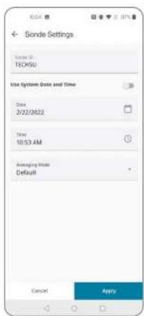
text_image
Sonde Settings Sonde ID: TECHSU Use System Date and Time Date 2/22/2022 Time 10:53 AM Ameraging Mode Default Cancel Apply-
Tap the Settings to adjust additional settings:
-
Custom ID
- Date and Time
-
Averaging Mode
-
Press Apply to save changes.
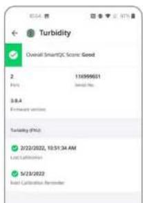
text_image
Turbidity Overall Smart/2C: Score: Good 2. 15999601 PVD: Standard Pos. 58.4 Frequency variation Turbidity (PVD) 3/22/2022, 10:51:34 AM Last Calibration 3/23/2022 Last Calibration Parameter-
On a Sensor details screen, you will see:
-
Port Number
- Serial Number
- Firmware Version
- QC Score
- Last Calibration Date
- Next Calibration Reminder (if enabled)

text_image
Conductivity Overall SmartQC Score Based 1 112099000 Port: Standard No. 3.0.5 Temperature range Calibration Int 2/17/2020 Low Calibration CT Settings ← CT Settings Reference Temp. 20 °C 25 °C End Temperature 5.75 Off Temperature Field 0.76 Up Current, Temp >: 0.04- Some sensors have additional settings:
- Conductivity/Temperature Sensor has options for the Reference Temperature, Cell Constant, TDS Conversion Factor, and Specific Conductance Temperature Coefficient

text_image
DO Overall SmartQC Score Bed 4 14/01/087 Port Serial No. 3.0.0 Sensor Cap Settings Calibration (bit) Factory Load Updated: 95%2014 C0030695 41D1F192 405564F0 3BD3F4AB BE1193FC 3C774CD3 BE4521DE KC- Dissolved Oxygen Sensor has options for the Sensor Cap Settings. This shows all K Values, DO Gain, and Cap Serial Number. These can be updated when a new Sensor Cap is installed.
- Press Apply to save changes.
4.12
Kor Mobile
Contact YSI
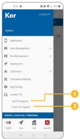
text_image
Kor 2.0.0.0 [71] Xylem Dashboard Data Management Site Management Deployment Calibration Instrument Settings App Setting Contact YSI Call YSI Support Email YSI Support EXOGO | Serial No. 178032826 18.00% N/A N/A SmartSCContact YSI
- Call YSI Support - Opens the phone app with the YSI phone number
- Email YSI Support - opens the phone email client with the support email address filled in
natural_image
Close-up of multiple cylindrical mechanical components arranged in a row (no visible text or symbols)5.1
EXO Sensors
Overview
The EXO product line includes sensors that detect a variety of physical, chemical, and biological properties of water. EXO sensors are designed to collect highly accurate data under ever-changing conditions.
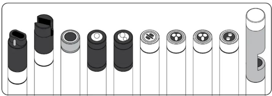
natural_image
Illustration of various cylindrical battery modules arranged in a row, with no visible text or symbols.Data Filtering
All EXO sensors share some common embedded software, including the filtering of real-time data. Sensors acquire environmental data at a constant rate, and use this stream of data as the input to the filtering algorithm that produces results seen by the user. EXO sondes collect data from the EXO sensors and are able to output data at rates up to 4 Hz.
Basic Rolling Filter
The filter is fundamentally a rolling or window average of past acquired inputs to the filter, such that as a new data value is added to the summation, the oldest data value is removed, and the total summation is divided by the total number of data values. It is a simple average, just rolling or moving in time. Starting with the February 2014 software release, different rolling time windows for the filter are now supported.
*TIP: Enable the Vertical Position parameter in the Depth unit options to view the real-time position of the sonde in the water column. This is helpful in profiling applications to ensure the sonde is lowered to the desired depth without waiting for the Depth data to stabilize.
NOTE: Making any changes to the Averaging Mode will stop a deployment. As a sonde takes measurements, it compares now readings to those taken in the previous 2-30 seconds (depending on the selected option). If the new reading is not significantly different than past measurements, then it merely factors into the rolling average with older data points to create a smooth curve. If the new reading is significantly different than past measurements, then it restarts the rolling average of data points.
To quickly check a sonde's Averaging Mode setting in Kor Software, check the bottom status bar and the word Default, Accelerated, or Rapid will be displayed adjacent to the sonde's serial number. To access Averaging Mode in Kor Mobile, tap Instrument Settings in the left stack menu, tap the sonde, then Sonde Settings. To access Averaging Mode with the handheld, press the Deploy button, select Sonde Settings, and then Averaging.
Adaptive Filtering
The drawback to a basic rolling filter is that response time to an impulse event is delayed, and the more entries in the average summation, the longer the delay for the result to converge on the true value. To correct this, the filter algorithm monitors the new data arriving and compares it to the current averaged result, looking for indication of an impulse event. When new data deviate from the average by more than a predetermined tolerance, the number of data entries within the rolling average is reduced to a minimum count and the remaining values are flushed with the new data. The result is a more accurate capture of the impulse event data, entirely eliminating the inherent delay caused by the rolling average.
Outlier Rejection
Every time a newly acquired data value is added, the rolling average entries are scanned for outlier data. Although such data has already been determined to fall within the tolerances defined above, the remaining worst offenders are removed from the rolling average calculation. This outlier rejection allows for smoother continuous data results.
Calibration Stability
During calibration, the filtering is active as described, plus an additional feature works to provide stability feedback to the user. When the user attempts to calibrate a sensor, the sudden changes in environment are perceived as impulses or plunge events and the filtering reacts accordingly. The results immediately show the value of the solution, and after a few moments, the filter
Calibration
Basic Overview

EXO Sensor Calibration
Watch Videos Now
EXO sensors (except temperature) require periodic calibration to assure high performance. Calibration procedures follow the same basic steps with slight variations for particular parameters. Calibration procedures described in this section will mainly focus on using Kor Software. Refer to Section 7.4 for calibration procedures using the EXO Handheld display and Section 4.10 for calibration procedures using a mobile device.
NOTE: All EXO sensors should be user calibrated before initial use.

text_image
Fill to line 2 Fill to line 1Calibration set-up
For accurate results, thoroughly rinse the EXO calibration cup with water, and then rinse with a small amount of the calibration standard for the sensor you are going to calibrate. Two to three rinses are recommended. Discard the rinse standard, then refill the calibration cup with fresh calibration standard. Alternatively, rinse the cal cup and sensors with deionized water, then dry with a lint-free cloth before filling with fresh calibration standard. Fill the cup to approximately the first line with a full sensor payload or the second line with small sensor payload. Recommended volumes will vary, just make certain that the sensor is submerged. Be careful to avoid cross-contamination with other standards.
Begin with clean, dry probes installed on the EXO sonde. Install the clean calibration guard over the probe(s), and then immerse the probe(s) in the standard and tighten the calibration cup onto the EXO sonde. We recommend using one sonde guard for calibration procedures only, and another sonde guard for field deployments. This ensures a greater degree of cleanliness and accuracy for the calibration procedure.
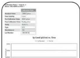
text_image
Conversion Rate 1 - Up to 1 Source: ISO-0000000000000000000000000000000000000000000000000000000000000000000000000000000000000000000000000000 Conversion Rate Positive / Positive Down / Down Pro Collection Rate Positive / Positive Down / Down Type Type Multifactor List Provider Up Call (p/Time) vs. Time Up Call (p/Time) vs. TimeBasic calibration in Kor Software
Go to the Calibrate menu in Kor Software. This menu's appearance will vary depending on the sensors installed in the sonde. Select the sensor you are going
Factory Reset Calibration
A Factory Reset Calibration can be performed to return the sensor gain and offset to factory specifications. Performing a Factory Reset Calibration will allow the user to start a calibration with default sensor metadata values. A new calibration of the sensor will then help with additional troubleshooting, if needed.
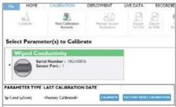
text_image
File: HOPE CALIBRATION DEPLOYMENT LIVE DATA RECORDED Calibration Fact Calibration Research Manage Sensor Report To 100 Report to 10% Select Parameter(s) to Calibrate Wiped Conductivity Serial Number : 18C1000% Sensor Part : 1 PARAMETER TYPE LAST CALIBRATION DATE Up Cost (USD)Performing a Factory Reset Calibration in Kor:
Step 1
Click on the Calibration tab or button.
Step 2
Click the turn-out arrow next to the parameter desired.

text_image
Are You Sure! Are you sure you would like to factory reset the calibration for the selected parameter? Enter calibration notes: YES NOStep 3
Click the Factory Reset Calibration button.
Step 4
Type any desired notes into the pop-up window and then click the Yes button to confirm the action.

Performing a Factory Reset Calibration in the Handheld:
Step 1
Click the Calibration button.
Step 2
Calibration
Calibration Report
The Calibration Report is a record of the calibration for an EXO sensor. The report contains quality assurance information including date and time of calibration, date of previous calibration, sensor firmware version, type of calibration performed, standard used, and QC Score.
Calibration Reports are saved in the Kor Software database on the computer or the EXO Handheld that was used during calibration (not on the sonde or the sensors). All reports can be accessed and viewed through the Calibration Records menu in Kor Software.
Sample Reports:
1-point calibration of specific conductance
on EXO Conductivity/Temperature probe

text_image
Calibration Record: Sensor Type: Wiped Conductivity And Temperature Last Calibration Time:1-point calibration of percent saturation
on EXO Optical Dissolved Oxygen probe
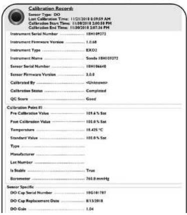
text_image
Calibration Records Sensor Type: DO Last Calibration Time: 11/21/2018 6:09:59 AM Calibration Start Time: 11/28/2018 2:00:58 PM Calibration End Time: 11/30/2018 5:07:34 PM Instrument Serial Number: 13H109272 Instrument Firmware Version: 1.0.68 Instrument Type: BXO2 Instrument Name: Sonde 1BH103272 Sensor Serial Number: 1BH106648 Sensor Firmware Version: 2.0.6 Calibrated By: Unknown Calibration Status Completed QC Score Good Calibration Poles #1 Pre Calibration Value: 109.6 % Sat Post Calibration Value: 100.0 % Sat Temperature: 16.425 °C Standard Value: 100.0 % Sat Type: Manufacturer: Last Number: Is Stable True Boremeter: 765.0 mmHg Sensor Specific DO Cap Serial Number: 18G101787 DO Cap Replacement Date: 8/13/2018 DO Gale: 1.04
SmartQC
Overview
SmartQC is a mechanism to normalize different sensors and to assess the current state of individual sensor performance relative to factory-defined performance parameters. Every EXO sensor has an embedded microprocessor which, along with calibration metadata, enables EXO to warn users of calibration errors or when a sensor is unable to be calibrated due to age, fouling, or damage, for example. For any sensor a QC Score is presented as red, yellow, or green:

A green SmartQC Score means the sensor is calibrated properly and all parameters used to assess its performance state are within factory-defined limits.

A yellow SmartQC Score means that the sensor will still perform within factory-defined limits, but that during calibration enough of an adjustment was required to suggest that the sensor is drifting from those limits or may soon require some adjustments, such as a new DO cap. A yellow QC Score might also result from variations in calibration standards and operators. One's comfort with a yellow score is case-dependent: for long-term deployments a yellow score is not optimal. For deployments of a couple of weeks or for spot-sampling, a yellow score may be perfectly acceptable, depending upon the sensor in question. This is addressed for individual sensors throughout the EXO Manual.

A red SmartQC Score means that the sensor is not performing within factory-specified limits. Also, in some cases a red QC Score might mean that a component of the sensor is due to be replaced (such as a DO cap), or the user has defined some other limit, such as the term expired since the most recent calibration. These examples are captured under the term SoftQC because they are set by the user in Kor software, and such settings will override a green SmartQC Score when using the software.
The way in which EXO assesses the calibration metadata is dependent upon the sensor type, and examples of information used include signal to noise ratio, signal gain, raw millivolts, and cell constants. "Gain" is one of the most common principles applied in the SmartQC system, and one might think of gain as m in the linear relationship y = mx + b where x is the real-time parameter result computed from a particular factory setting and y is the same parameter but modified and computed from a setting as defined by the user's calibration.
For example suppose that during a calibration the % ODO saturation is calculated from the factory settings to be 92% . This would be x . This same setting may be calculated to be 97% during the user's calibration, and this would be y . The gain, or m , would be calculated to be 1.054, and in this specific example that would be reported in the calibration worksheet as the ODO Gain
5.5
Conductivity / Temperature
Sensor Overview
The EXO combination conductivity and temperature sensor should be installed in nearly all sonde applications. Not only will this sensor provide the most accurate and fastest response temperature data, but it will also provide the best data for the use in temperature compensation for the other EXO probes. The conductivity data is used to calculate salinity, non-linear function (nLF) conductivity, specific conductance, and total dissolved solids, and compensate for changes in density of water (as a function of temperature and salinity) in depth calculations if a depth sensor is installed.
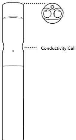
text_image
Conductivity CellSpecifications
Conductivity
| Default Units μS/cm, mS/cm | |
| Temperature | |
| Operating | -5 to +50°C |
| Storage | -20 to +80°C |
| Range 0 to 200,000 μS/cm | |
| Accuracy | 0-100,000 μS/cm: ±0.5% of reading or 1 μS/cm, whichever is greater; 100,000-200,000 μS/cm: ±1% of reading |
| Response T63<2 sec | |
| Resolution | 0.1 to 10 μS/cm range dependent |
| Sensor Type 4-electrode nickel cell | |
Temperature
The temperature sensor uses a highly stable and aged thermistor with extremely low-drift characteristics. The thermistor's resistance changes with temperature. The measured resistance is then converted to temperature using an algorithm. The temperature sensor receives a multi-point NIST traceable wet calibration and the accuracy specification of 0.01^ C is valid for expected life of the probe. No calibration or maintenance of the temperature sensor is required, but accuracy checks can be conducted against a NIST-traceable temperature probe supplied by the user.
Conductivity Electrodes
The conductivity sensor uses four internal, pure-nickel electrodes to measure solution conductance. Two of the electrodes are current driven, and two are used to measure the voltage drop. The measured voltage drop is then converted into a conductance value in millisiemens (millimhos). To convert this value to a conductivity value in millisiemens per cm (mS/cm), the conductance is multiplied by the cell constant that has units of reciprocal cm (cm^-1) . The cell constant for the conductivity cell is approximately 5.1/ cm ± 10% . For most applications, the cell constant is automatically determined (or confirmed) with each deployment of the system when the calibration procedure is followed.
Temperature Compensation
EXO sensors have internal thermistors for quality assurance purposes. Turbidity uses the internal thermistor for temperature compensation, while all other EXO sensors reference the C/T probe for temperature compensation. To display and log temperature, a C/T probe must be installed in an EXO sonde. Thermistor readings are logged in the sonde's raw data-viewable in Kor Software-but are not included in data exported to Excel.
Conductivity = This is a measurement of water conductance from the drive and sense electrodes on the conductivity electrode. The output is in mS/cm or S/cm. Note that the conductivity of solutions of ionic species is highly dependent on temperature, and the conductivity output is NOT compensated for temperature.
Specific Conductivity = When Specific Conductance is selected, the sonde uses the temperature and raw conductivity values associated with each determination to generate a specific conductance value compensated to 25^ C by default. Both the Temperature Coefficient and reference temperature can be adjusted in the advanced sensor menu under calibration.
nLF Conductivity - The non-linear function (nLF) is defined by the ISO 7888 standard and is applicable for the temperature compensation of electrolytic conductivity of natural waters. This convention is typically used in German markets.
5.6
Conductivity / Temperature
Calibration
Clean the conductivity cell with the supplied soft brush before calibrating (see Section 6.7). A clean and dry Conductivity sensor will read zero in air, with an allowable tolerance of 3 S / cm .
Also, review the basic calibration description in Section 5.2.
This procedure calibrates conductivity, non-linear function (nLF) conductivity, specific conductance, salinity, and total dissolved solids.
A variety of standards are available based on the salinity of your environment. Select the appropriate calibration standard for your deployment environment; we recommend using standards greater than 1 mS/cm (1000 S/cm) for greatest stability.
Four conductivity standard into a clean and dry or pre-rinsed EXO calibration cup. YSI recommends filling the calibration cup up to the second marked line to ensure the standard is above the vent holes on the conductivity sensor. Immerse the probe end of the sonde into the solution, gently rotate and/or move the sonde up and down to remove any bubbles from the conductivity cell.
Allow at least one minute for temperature equilibration before proceeding.
In the Calibrate menu, select the Conductivity sensor and then select the parameter you wish to calibrate. These parameters may include conductivity, nLF conductivity, specific conductance, or salinity. Calibrating any one option automatically calibrates the other parameters. After selecting the option of choice (specific conductance is normally recommended), enter the value of the standard used during calibration. Be certain that the units are correct (microsiemens, not millisiemens).
Observe the Pre Calibration Value readings and the Data Stability, and when they are Stable, click Apply to accept this calibration point.
NOTE: If the data do not stabilize after 40 seconds, gently rotate the sonde or remove/reinstall the cal cup to make sure there are no air bubbles in the conductivity cell.
Click Complete. View the Calibration Summary screen and QC Score. Click Exit to return to the sensor calibration menu.
Rinse the sonde and sensor(s) in tap or purified water and dry.
SmartQC for Conductivity/Temperature Sensors
The SmartQC Score for conductance is based on a gain factor, which is then computed into a cell constant that appears on the Calibration Report. The gain may drift over time due to aging electrodes and wear, and this will ultimately affect the cell constant.

An ideal cell constant is dependent upon the type of conductivity sensor; there are two types of conductivity sensors (wiped and non-wiped) on the EXO platform:
- For non-wiped conductivity [599870], the ideal cell constant = 5.1/cm ± 10%
The CT sensor can be evaluated in air when it is new, and as the sensor ages this may be a useful tool for assessing its drift from factory performance. To perform an air check:
- Clean the sensor thoroughly.
- Perform a Factory Reset Calibration.
- Rinse the sensor with DI water and dry it thoroughly.
- Observe sensor readings in air. They should be very close to zero. While this is a subjective assessment, if the user has an idea of what air readings were when the sensor was new, monitoring this on occasion can provide clues as to whether the sensor is aging out of use.
Guidance on interpretation of the SmartQC Score for this sensor is as follows:

Green: Gain is within acceptable limits. Calibration was performed successfully and resulted in a gain within factory specified limits.

Yellow: The gain has drifted a minor amount from factory specified limits. The sensor is still reporting correctly but adjustments may need to be made. If a user calibration results in a yellow QC Score, perform the following actions:
- Thoroughly clean the sensor and ensure that all debris is removed from the surfaces of the sensor. Refer to Section 6.7 for additional information on how to properly clean the sensor in order to avoid damaging the sensor.
- Next, perform a Factory Reset Calibration to reset the gain and cell constant to their factory default values. This is described in Section 5.2.
- Check specific conductivity readings in air, and verify they are less than 1 S/cm. If reading higher in air, thoroughly clean the sensor, and allow it to dry completely before checking in air again.
- Complete another calibration on the sensor using fresh standard solution.
5.7
Wiped Conductivity / Temperature
Sensor Overview
Biofilms, barnacles, and algal growth are common culprits of poor data quality, clogging up conductivity cells and coating sensor optics. While the EXO Central Wiper can mechanically remove biofouling from other sensors to maintain data integrity over long deployment periods, in particularly high fouling environments the EXO Wiped C/T sensor provides superior conductivity data by avoiding stagnant readings and reducing the impact of micro-environments.
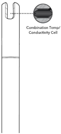
text_image
Combination Temp/ Conductivity CellEXO Wiped C/T Considerations
Sensor performance and specifications are well suited for continuous monitoring applications, where the EXO sonde is installed at a fixed location. For sampling and vertical profiling applications the standard Conductivity Temperature probe [part #599870] which has a much faster temperature response should be used.
The Wiped C/T will have a different cell constant than the standard Conductivity probes. A nominal cell constant of 0.469/cm +/-0.05 is typical on wiped conductivity.
The EXO Central Wiper [599090] must have the wiper shaft seal serviced in the past year to use with the-wiped C/T probe. The wiper will work harder grooming the sensor, therefore if your wiper hasn't had the shaft seal properly maintained there is a chance it could stall mid deployment.
Specifications
Conductivity
| Default Units μS/cm, mS/cm | |
| Temperature | |
| Operating | -5 to +50°C |
| Storage | -20 to +80°C |

Wiped Conductivity / Temperature Calibration and Deployment
Calibration
A wet calibration of your new conductivity sensor should be completed before initial use. It is recommended that you complete a single point calibration in a standard similar to the conductivity readings that you expect to measure. It is recommended not to use standards below 1,000 S/cm for fresh water applications as they can become easily contaminated. The temperature sensor cannot be user calibrated. Best practice is to periodically test the performance of the temperature sensor against a NIST traceable thermometer at several reference points.
NOTE: All EXO sensors should be user calibrated before initial use.
Deployment Setup
The Wiped C/T sensor is optimized for continuous monitoring where a variety of environmental fouling conditions would affect the performance of the sensor without wiping. Numerous solutions can be employed to mitigate the effects of biofouling. These can include the use of copper tape, anti-fouling guards, anti-fouling paints, as well as local techniques developed for site specific challenges. However, none of these options can be directly applied to the conductivity cell of the Wiped C/T sensor. Using the Central Wiper to groom the conductivity cell before readings prevents biofouling-induced drift of the conductivity cell.
The sensor includes a new central wiper brush [part #599673]. A brush's wear and replacement intervals vary greatly based on specific application challenges, but 2-12 months use has been observed. Below are three examples of brush wear that will occur with use. It is recommended the wiper brush be replaced before it reaches level 3 for optimal cleaning. We recommend using a new wiper brush with the initial deployment.
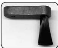
Level 1- New brush, minimal "splay"

Level 2- Moderate splaying, have spare ready
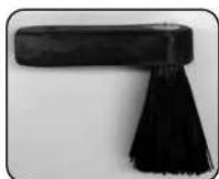
Level 3- Excessive splay, replace to prevent stalling of wiper
NOTICE: It is not recommended using Wiped C/T in conjunction with EXO Ammonium, Nitrate, or Chloride electrodes as they are protected with a guard which accelerates the brush splay.
SmartQC for Wiped Conductivity/Temperature Sensors
The SmartQC Score for conductance is based on a gain factor, which is then computed into a cell constant that appears on the Calibration Report. The gain may drift over time due to aging electrodes and wear, and this will ultimately affect the cell constant.
An ideal cell constant is dependent upon the type of conductivity sensor; there are two types of conductivity sensors (wiped and non-wiped) on the EXO platform:
- For wiped conductivity [599827], the ideal cell constant = 0.469/cm ± 0.05
Guidance on interpretation of the SmartQC Score for this sensor is as follows:

Green: Gain is within acceptable limits. Calibration was performed successfully and resulted in a gain within factory specified limits.

Yellow: The gain has drifted a minor amount from factory specified limits. The sensor is still reporting correctly but adjustments may need to be made. If a user calibration results in a yellow QC Score, perform the following actions:
- Thoroughly clean the sensor and ensure that all debris is removed from the surfaces of the sensor. Refer to Section 6.7 for additional information on how to properly clean the sensor in order to avoid damaging the sensor.
- Next, perform a Factory Reset Calibration to reset the gain and cell constant to their factory default values. This is described in Section 5.2.
- Check specific conductivity readings in air, and verify they are less than 1 S/cm. If reading higher in air, thoroughly clean the sensor, and allow it to dry completely before checking in air again.
- Complete another calibration on the sensor using fresh standard solution.
If the QC Score remains yellow, the sensor is still able to be used, but the user should monitor this sensor during calibrations, including looking at the cell constant on the Calibration Reports.

Red: The gain has drifted significantly from the factory specified limits, and the sensor may not report correct values. If a user calibration results in a red QC 5core, perform the following actions:
- Verify that the standard value used during calibration was entered correctly. If the value was not entered correctly, the resulting QC Score would show a red value due to the gain changing significantly.
- Thoroughly clean the sensor and ensure that all debris is removed from the surfaces of the sensor. Refer to Section 6.7

Depth and Level
Sensor Overview
EXO measures depth of water with a non-vented strain gauge. (See Section 8 if your sonde is equipped with vented level.) A differential strain gauge transducer measures pressure with one side of the transducer exposed to the water and the other side exposed to a vacuum. We calculate depth from the pressure exerted by the water column minus atmospheric pressure. Factors influencing depth measurement include barometric pressure, water density, and temperature. Calibration in the atmosphere "zeros" the sensor with respect to the local barometric pressure. A change in barometric pressure will result in a zero shift unless the transducer is recalibrated to the new pressure.
EXO sondes have intake openings to allow water to act on the strain gauge. The EXO1 and EXO1 ^1 intake is located above the label of the sonde. The EXO2, EXO2 ^5 , EXO3, and EXO3 ^5 intake openings are two small holes on the face of the sonde bulkhead.

natural_image
Pure diagram of a mechanical component with no text, numbers, or symbolsDepth Sensor Location relative to other water quality sensors (see EXO sonde label)
Depth Sensor Location 27.2 cm (EXO1), 13.9 cm (EXO2) to WQ Sensors

Location of Depth Sensor
Depth sensors on the EXO2 and EXO3 sondes are not on center. When deploying the sonde vertically, take care to ensure the sonde is redeployed in same position. Often a marker pin inside a PVC pipe is used. In horizontal deployments, take care to ensure the redeployments are always in the same orientation. This is especially important for the EXO2 and EXO3 sondes because the depth sensor is off-axis.
To assist with consistent horizontal orientation, the EXO2 and EXO3 sondes have an indentation at the top of the sonde for a marker or positioning pin.
The sonde should be installed with at least 1 cm of water above the intake ports. If a conductivity sensor is installed, the depth will be compensated automatically for changes in the density of water as temperature and salinity change.
Depth Configuration
EXO sondes must be ordered with a specific depth sensor option: 599xx50x-00 = no depth 599xx50x-01 = 0-10 m depth
599xx50x-02 = 0-100 m depth 599xx50x-03 = 0-250 m depth 599xx50x-04 = 0-10 m vented level
The depth configuration must be chosen at time of ordering. Once a sonde is shipped with a depth configuration it cannot be changed by the user.
5.10
Depth and Level Calibration
NOTE: This calibration option is available only if your sonde is equipped with an integral depth sensor or a vented level sensor.
For the calibration, make certain that the depth sensor or vented level sensor is in air and not immersed in any solution. Also, review the basic calibration description in Section 5.2:
In the Calibrate menu, select Depth and then select Calibrate.
0 is the only acceptable calibration value. An offset may be entered under the Depth sensor settings. See "Advanced" below.
Observe the Pre Calibration Value readings and the Data Stability, and when they are Stable, click Apply to accept this calibration point. This process zeros the sensor with regard to current barometric pressure.
Click Exit to return to the sensor calibration menu.
For best performance of depth measurements, users should ensure that the orientation of the sonde remains constant while taking readings. This is especially important for vented level measurements. Keep the sonde still and in one position while calibrating.
Advanced
Configure Depth Settings by selecting the Depth Sensor under the Instrument and Sensors menu.
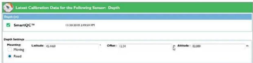
text_image
Latest Calibration Data for the Following Sensor: Depth Depth (m) SmartQC™ 11/30/2018 2:49:59 PM Depth Settings Mounting: Laxitude: 45.4469 Offset: 12.34 Altitude: 82.089 m Moving FixedSmartQC for Depth
The SmartQC Score for depth and vented level is based upon an expected offset that would be computed by the sensor at the time of calibration.
Guidance on interpretation of the SmartQC Score for this sensor is as follows:

Green: The offset computed during the calibration is within factory specified limits.

Yellow: The offset computed during the calibration is near the threshold of factory specified limits. If a user calibration results in a yellow QC Score, perform the following actions:
- If the sensor is being deployed at high altitudes, the computed offset during calibration may be outside of the factory specified limits. The data collected by the depth sensor at higher elevations is not incorrect; simply the offset is outside of normal lower-elevation ranges. At higher elevations, all sensors may experience the yellow QC Score and a green QC Score may never be attainable.
- Ensure that the sensor is free of debris. If there is debris clogging the inlet, use water to clear the inlet. Use care to avoid damaging the thin pressure membrane. Refer to Section 6.5 for additional information on how to properly clean the instrument in order to avoid damaging the sensor.
- Make sure that the sensor was completely dry before performing the calibration. If needed, use a can of compressed air to dry off the sensor to perform a better calibration. Do NOT stick any tools or utensils inside the pressure sensor vent hole. The sensor membrane is extremely thin and easily punctured.
- Perform a Factory Reset Calibration to restore the offset to factory calibrated values and then perform another calibration.
- Vented Only: Verify that the tube exposed to atmospheric conditions is properly connected to a desiccant canister or connected to a dummy plug to prevent moisture from entering the vent tube. If moisture accumulates in the vent tube, calibrations will not be accurate. Information on how to connect a desiccant container to a vented level sonde can be found in Section 8.
If the QC Score is still yellow after performing another calibration, the sensor is still able to be used. The user should continue to monitor the sensor for additional drift away from the factory defaults.

Red: The offset computed during the calibration is outside of factory specified limits. If a user calibration results in a red QC Score, perform the following actions:
5.11
Dissolved Oxygen
Sensor Overview
The principle of operation of the EXO Optical Dissolved Oxygen sensor is based on the well-documented concept that dissolved oxygen quenches both the intensity and the lifetime of the luminescence associated with a carefully chosen chemical dye. The EXO DO sensor operates by shining a blue light of the proper wavelength on this luminescent dye which is immobilized in a matrix and formed into a disk. The blue light causes the immobilized dye to luminesce and the lifetime of this dye luminescence is measured via a photodiode in the probe. To increase the accuracy and stability of the technique, the dye is also irradiated with red light during part of the measurement cycle to act as a reference in the determination of the luminescence lifetime.


Sensor Cap

Sensor without Sensor Cap
When there is no oxygen present, the lifetime of the signal is maximal; as oxygen is introduced to the membrane surface of the sensor, the lifetime becomes shorter. Thus, the lifetime of the luminescence is inversely proportional to the amount of oxygen present and the relationship between the oxygen pressure outside the sensor and the lifetime can be quantified by the Stern-Volmer equation: (Tzero/T)-1 versus O_2 pressure.
For most lifetime-based optical DO sensors, this Stern-Volmer relationship is not strictly linear (particularly at higher oxygen pressures) and the data must be processed using analysis by polynomial non-linear regression. Fortunately, the non-linearity does not change significantly with time so that, as long as each sensor is characterized with regard to its response to changing oxygen pressure, the curvature in the relationship does not affect the ability of the sensor to accurately measure oxygen for an extended period of time.
Specifications
Units % Saturation, mg/L, % CB, % RTB
Variables that Affect DO Measurements
Variables that could affect dissolved oxygen measurements include temperature, salinity, and barometric pressure. Temperature and salinity are compensated for during instrument calibration and field use with real-time readings from the EXO Conductivity/Temperature sensor and/or instrument software settings.
Barometric pressure relates to the pressure of oxygen in the calibration environment, and barometric pressure changes due to a change in altitude or local weather. Generally the effect of barometric pressure is overcome by proper sensor calibration to a standard pressure.
DO can be reported in mg/L (equivalent to ppm), calculated by the sensor using standard methods. There are three options for reporting DO % in Kor Software: %Sat, %CB, and %RTB. Local DO refers to dissolved oxygen calibrated to 100% at a specific location without correcting for barometric pressure. Normally a dissolved oxygen percent saturation (%Sat) calibration is based on readings from a barometer or a user specified value of barometric pressure. Only when barometric pressure is 760 mmHG will the DO sensor calibrate to 100%; any other pressure reading can result in a calibration and output less or greater than 100%.
ODO % Sat = Direct DO measurement provided by the sensor, corrected with temperature and local barometric (Saturation) pressure at the time of calibration: (local mmHg / 760 mmHg) x 100 = %5at
Some users prefer to measure a dissolved oxygen percentage that is specific to a particular location without the effect of barometric pressure influencing their readings. With that in mind, YSI offers two parameters available for users that wish to measure Local DO:
ODO % CB = Local DO value calculated from the barometric pressure value entered at the time of calibration. This (Calibrated Barometer) is only relevant for monitoring applications where the DO sensor cannot receive a continuous barometric pressure input during the deployment.
ODO % RTB = Local DO value calculated from the barometric pressure readings from the real-time barometer (Real-Time Barometer) that is built into a handheld. This is relevant for sampling applications where the DO sensor receives continuous barometric pressure input from the handheld meter and readings are updated accordingly.

Dissolved Oxygen
Calibration
First review the basic calibration description in Section 5.2.
ODO % Sat and ODO % local - 1-point
Place the sonde with sensor into either water-saturated air or air-saturated water:
(a) Water-saturated air: Ensure there are no water droplets on the DO sensor or the thermistor. Place into a calibration cup containing about 1/8 inch of water that is vented by loosening the threads. (Do not seal the cup to the sonde.) Wait 10-15 minutes before proceeding to allow the temperature and oxygen pressure to equilibrate. Keep out of direct sunlight.
(b) Air-saturated water: Place into a container of water which has been continuously sparged with an aquarium pump and air stone for one hour. Wait approximately 5 minutes before proceeding to allow the temperature and oxygen pressure to equilibrate.
In the Calibrate menu, select ODO, then select ODO % Sat or ODO % local (% CB or % RTB.) Calibrating in ODO % Sat automatically calibrates ODO mg/L and ODO % local and vice versa.
NOTE: ODO % RTB is only available when the sonde is connected to the EXO Handheld or EXO GO. The barometric pressure will automatically populate in the calibration window.
For % CB, enter the current barometric pressure in mm of Hg (Inches of Hg x 25.4 = mm Hg).
NOTE: Laboratory barometer readings are usually "true" (uncorrected) values of air pressure and can be used "as is" for oxygen calibration. Weather service readings are usually not "true", i.e., they are corrected to sea level, and therefore cannot be used until they are "uncorrected". An approximate formula for this "uncorrection" (where the BP readings MUST be in mm Hg) is: True BP = [Corrected BP] - [2.5 * (Local Altitude in ft above sea level/100)]
Observe the Pre Calibration Value readings and the Data Stability, and when they are Stable, click Apply to accept this calibration point.
Click Complete. View the Calibration Summary screen and QC Score. Click Exit to return to the sensor calibration menu.
mg/L - 1-point
Place the sonde with sensor in a container which contains a known concentration of dissolved oxygen in mg/L and that is within ± 10% of air saturation as determined by one of the following methods:
- Winkler titration
ODO % Sat, ODO % local or mg/L - 2-point (or zero point)
Normally it is not necessary to perform a 2-point calibration for the DO sensor, and the procedure is not recommended unless (a) you are certain that the sensor does not meet your accuracy requirements at low DO levels and (b) you are operating under conditions where you are certain to be able to generate a medium which is truly oxygen-free.
For ODO % Sat or ODO % local, calibrate your sonde at zero oxygen and in water-saturated air or air-saturated water. For ODO mg/L, calibrate your sonde at zero oxygen and a known concentration of oxygen within ±10% of air-saturation. The key to performing a 2 point calibration is to make certain that your zero oxygen medium is truly oxygen-free:
- If you use nitrogen gas for the zero-point calibration, make certain that the vessel you use has a small exit port to prevent back diffusion of air and that you have completely purged the vessel before confirming the calibration.
- If you use sodium sulfite solution for the zero-point calibration, a solution can be made by dissolving approximately 8-10 grams of sodium sulfite into 500~mL of tap water. Mix the solution thoroughly. It may take the solution 60 minutes to be oxygen-free.
Place the sonde with DO and temperature sensors in the zero-oxygen medium.
In the Calibrate menu, select ODO, then select either ODO % Sat, ODO % CB, ODO % RTB, or ODO mg/L.
Select Zero from the Standard Value drop-down window.
Observe the Pre Calibration Value readings and the Data Stability, and when they are Stable, click Apply to accept this calibration point.
- If you used sodium sulfite solution as your zero calibration medium, you must thoroughly remove all traces of the reagent from the probes and wiper prior to proceeding to the second point. We recommend that the second calibration point be in air-saturated water if you use sodium sulfite solution.
Next place the sensors in the medium containing a known oxygen pressure or concentration and wait at least 10 minutes for temperature equilibration. Click Add Another Cal Point. Then enter either the barometer reading in mm Hg (for ODO %) or the actual concentration of oxygen as determined from a Winkler titration (for ODO mg/L), for instance. Observe the Pre Calibration Value readings and the Data Stability, and when they are Stable, click Apply to accept this calibration point.
Click Complete. View the Calibration Summary screen and QC Score. Click Exit to return to the sensor calibration menu.
SmartQC for Optical Dissolved Oxygen Sensors
Dissolved Oxygen (DO) calculations are derived from polynomial equations based on the K1-K7 coefficients that are provided with each new EXO Dissolved Oxygen sensor cap. Each sensor has been thoroughly tested during the production process to generate these unique calibration coefficients. Calibration of the probe essentially changes these coefficients. The DO SmartQC
Score is based on a gain factor, which relates to the magnitude of coefficient change. The gain may drift as the sensor gets older and the optics begin to fade and may also be affected by the degradation of or damage to the unique material that is on the face of the sensor. If a zero-DO calibration is performed, SmartQC also calculates a zero-DO coefficient change.
Guidance on interpretation of the SmartQC Score for this sensor is as follows:

Green: Gain is within acceptable limits. Calibration was performed successfully and resulted in a gain within factory specified limit.

Yellow: The gain or zero-DO calibration coefficient has drifted a minor amount from the factory specified limits. The sensor is still reporting correctly but adjustments may need to be made. If a user calibration results in a yellow QC Score, perform the following actions:
- Thoroughly clean the sensor and ensure that all debris is removed from the surfaces of the sensor. Refer to the Section 6.9 of the manual for additional information on how to properly clean the instrument in order to avoid damaging the sensor.
- If the sensor has been left in dry air for longer than eight hours, it must be rehydrated. To rehydrate, soak the DO sensor cap in warm (room temperature) tap water for approximately 24 hours. Following the soak, calibrate the sensor and store it in a moist environment.
- Ensure that proper calibration procedures were followed. Typical errors include not allowing enough time for the calibration chamber to come to equilibrium with the atmosphere or the chamber was not of adequate humidity. Time to equilibrate to an air-saturated water chamber may also not have been adequate. It is recommended to allow between 10-15 minutes for equilibration.
- Check the lens cap for scratches. If there are scratches, the resulting gain after calibration may change because the amount of membrane remaining on the lens cap has changed.
- If a new lens cap was installed, a. ensure that the new calibration coefficients were entered into the sensor using either the handheld or Kor Software. The software will calibrate the sensor and also compute the QC Score based on the old lens cap coefficients if the values are not changed after installation of the new lens cap.

Red: The gain or zero-DO calibration coefficient has drifted significantly from the factory specified limits and the sensor may not report correct values. If a user calibration results in a red QC Score, perform the following actions:
- Thoroughly clean the sensor and ensure that all debris is removed from the surfaces of the sensor. Occasionally, thin films from sediment may affix to the lens cap surface and will affect readings and calibrations. Refer to the Section 6.9 of the manual for additional information on how to properly clean in order to avoid damaging the sensor cap.
- If the sensor has been left in dry air for longer than eight hours, it must be rehydrated. To rehydrate, soak the DO sensor cap in warm (room temperature) tap water for approximately 24 hours. Following the soak, calibrate the sensor and store it in a moist environment.
- Ensure that proper calibration procedures were followed. Gross errors can cause the gain to change significantly from factory default values. Errors in calibration include sealing the calibration cup to the sonde completely, allowing the calibration setup to equilibrate in the sun, or not properly saturating the air environment with water.
- Inspect the lens caps for coating loss on the sensor window. If the sensor cap has excessive coating loss to the point that calibration is being affected, replace the sensor lens cap. Re-enter the calibration coefficients, execute a Factory Reset Calibration and perform a calibration on the newly installed sensor lens cap.
- Verify that proper calibration coefficients were entered if the sensor lens cap was replaced.
- If a zero-DO calibration was performed, perform a Factory Reset Calibration and redo the 2-point calibration procedure. Allow for ample time for the sensor to equilibrate to both zero and 100% saturation values.
If the OC Score returns to red after the above steps were attempted, please contact YSI Technical Support for further assistance.

fDOM
Sensor Overview
The EXO fDOM (Fluorescent Dissolved Organic Matter) sensor detects the fluorescent component of DOM (Dissolved Organic Matter) when exposed to near-ultraviolet (UV) light.
Colored Dissolved Organic Matter
Users might wish to quantify colored dissolved organic matter (CDOM) in order to determine the amount of light which is absorbed by stained water and thus is not available for photosynthesis. In most cases, fDOM can be used as a surrogate for CDOM.
Quinine Sulfate
A surrogate for fDOM is quinine sulfate, which, in acid solution, fluoresces similarly to dissolved organic matter. The units of fDOM are quinine sulfate units (QSUs) where 1 QSU = 1 ppb quinine sulfate and thus quinine sulfate is really an indirect surrogate for the desired CDOM parameter.


CAUTION
Δ UV LIGHT
Do not look
directly at the end the of sensor when it is active.
The EXO fDOM sensor shows virtually perfect linearity ( R^2=1.0000 ) on serial dilution of a colorless solution of quinine sulfate. However, on serial dilution of stained water field samples, the sensor shows some underlinearity. The point of underlinearity in field samples varies and is affected by the UV absorbance of the DOM in the water. Testing shows that underlinearity can occur at fDOM concentrations as low as 50 QSU. This factor means that a field sample with an fDOM reading of 140 QSU will contain significantly more than double the fDOM of a sample that reads 70 QSU. This effect—good linearity in colorless quinine sulfate solution, but underlinearity in stained field samples—is also exhibited by other commercially available fDOM sensors and thus the performance of the EXO sensor is likely to be equivalent or better than the competition while providing the advantages of easy integration into a multiparameter package and automatic mechanical cleaning when used in monitoring studies with an EXO2 or EXO3 sonde.
Specifications
5.14
fDOM
Calibration Standards
Quinine Sulfate Solution for fDOM Sensor
⚠ WARNING: Before using a quinine sulfate reagent (solid or solution) or sulfuric acid reagent, read the safety instructions provided by the supplier. Take extra precautions when making dilutions of concentrated sulfuric acid, as this reagent is particularly dangerous. Remember that only trained personnel should handle chemicals.
Preparation
Use the following procedure to prepare a 300~ g / L solution of quinine sulfate (300 QSU) that can be used to calibrate the EXO fDOM sensor for field use:
- Purchase solid quinine sulfate dihydrate (CAS# 6119-70-6) with a high purity (>99%).
NOTE: YSI uses quinine sulfate dihydrate produced by Acros Organics (Thermo Fisher Scientific, acros.com) for factory calibration of fDOM sensors. For best results, purchase from this manufacturer.
-
Purchase 0.1 N (0.05 M) sulfuric acid (CAS# 7664-93-3), to avoid the hazards and introduced error of diluting concentrated sulfuric acid to make this reagent.
-
Weigh 0.100 g of solid quinine sulfate dihydrate and quantitatively transfer the solid to a 100-mL volumetric flask. Dissolve the solid in about 50 mL of 0.05 M (0.1 N) sulfuric acid ( H_2SO_4 ), dilute the solution to the mark of the volumetric flask with additional 0.05 M sulfuric acid, and mix well by repeated inversion. This solution is 1000 ppm in quinine sulfate (0.1%) and can be stored in a darkened or amber glass bottle for up to 2 years unopened, and 6 months with regular use.
NOTE: For lowest possible error when weighing the quinine sulfate dihydrate, use an analytical balance. Note that more error will be introduced if using instruments with low precision.
- Transfer 0.3 mL of the 1000 ppm solution to a 1000 mL volumetric flask and then fill the flask to the top graduation with 0.05 M sulfuric acid. Mix well to obtain a solution of 300 g/L (300 QSU or 100 RFU).
NOTE: Using a lab-grade volumetric flask and high-precision pipet, such as a volumetric pipet or micropipette, will decrease the amount of error introduced in this step.
- The dilute standard prepared in the previous step should be used within 90 days of preparation and should be discarded immediately after exposure to EXO's metal components.
Degradation of quinine fluorescence by copper and chloride
NOTICE: Exposure of the quinine sulfate solution to any copper-based component of the EXO sonde and sensors (primarily

fDOM Calibration
Review the basic calibration description in Section 5.2.
NOTE: User calibration is required to ensure the sensor is performing optimally. LED degradation over time is natural, but is corrected with this procedure.
Before calibrating, be certain that the sensing window is clean (cleaning instructions, Section 6.6).
This procedure calibrates fDOM RFU or fDOM QSU/ppb. If the user has both units selected, then this procedure must be performed twice, once for each unit, to completely calibrate the parameter.
For 2-point calibrations, the first standard must be clear water (0 g/L). The second standard should be a 300 g/L quinine sulfate solution. For detailed instructions for mixing this solution, see Section 5.14.
NOTE: Do not leave sensors in quinine sulfate solution for a long time. A chemical reaction occurs with the copper on the sonde (wiper assembly, sonde bulkhead, copper tape) that degrades the solution and causes it to drift. Also, start with very clean sensors, as the presence of chloride and halide ions (from estuarine or seawater, conductivity standards, and Zobell solution) can compromise QS fluorescence.
QSU - 1- or 2-point
Pour the correct amount of clear deionized or distilled water into the calibration cup. Immerse the probe end of the sonde in the water.
In the Calibrate menu, select fDOM, then select QSU/ppb. Select either a 1- or 2-point calibration. Enter 0 for first standard value and 300 g/L for second standard value.
Observe the Pre Calibration Value readings and the Data Stability, and when they are Stable, click Apply to accept this calibration point.
Remove the Central Wiper before proceeding to the next step.
Next place the sensors in the correct amount of 300 g/L quinine sulfate standard in the calibration cup. Click Add Another Cal Point in the software. Observe the Pre Calibration Value readings and the Data Stability. While stabilizing, verify that no air bubbles reside on the sensing face of the sensor. If there are bubbles, gently shake or move the sensor to dislodge. When data are Stable, click Apply to accept this calibration point.
SmartQC for fDOM Sensors (RFU or QSU)
The SmartQC Score for IDOM is based on a gain factor and an offset factor. Both of these values may change as the sensor and the optics age.
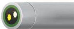
Guidance on interpretation of the SmartQC Score for this sensor is as follows:

Green: Gain and offset are within acceptable limits. Calibration was performed successfully and results are within factory specified limits.

Yellow: The sensor gain or offset is near the threshold of calibration limits. If a user calibration results in a yellow QC Score, perform the following actions:
- Perform a Factory Reset Calibration and complete a recalibration.
a. If performing a 1-point calibration, use fresh, clear water.
b. If performing a 2-point calibration, use fresh, clear water and freshly made quinine sulfate solution. - Ensure that the standard value was entered correctly. Calibration of fDOM is temperature dependent; make sure the appropriate value from the table in Section 5.14 was entered during calibration for either RFU or QSU.
- Ensure that the sensor is free of contamination. Refer to Section 6.6 for additional information on how to properly clean the sensor in order to avoid damage.
- Ensure the copper tape and the central wiper brush are removed from the sonde. Copper quenches fluorescence of quinine sulfate, which will interfere with the calibration.
If the QC Score returns to yellow, the sensor is still able to be used, but the user should monitor this sensor during calibrations for any further drift.

Red: The sensor gain or offset are outside of factory specified limits. If a user calibration results in a red QC Score, follow the same steps described above for a yellow QC Score.
If the QC Score remains red, please contact YSI Technical Support for further assistance.
5.16
ISEs: Ammonium, Nitrate, & Chloride Sensors Overview
NOTE: Ammonium, nitrate, and chloride ion-selective electrodes (ISEs) should be used in freshwater applications only at depths of less than 55 feet (17 meters) and less than 25 psi.
The ammonium and nitrate sensors use a silver/silver chloride wire electrode in a custom filling solution. The internal solution is separated from the sample medium by a polymer membrane, which selectively interacts with ammonium or nitrate ions. When the sensor is immersed in water, a potential is established across the membrane that depends on the relative amounts of ions in the sample and the internal solution. This potential is read relative to the Ag/AgCl reference electrode.

text_image
Guarded Sensor Tip Replaceable Sensor BaseSpecifications
Ammonium - NH _4
| Units mg/L-N, mill volts | |
| Temperature | |
| Operating | 0 to 30°C |
| Storage | 0 to 30°C |
| Depth 0 to <55 ft (0 to <17 m) | |
| Range 0 to 200 mg/L-N | |
| Accuracy | ±10% of reading or ±2 mg/L-N, whichever is greater |
| Response T63<30 sec | |
| Resolution 0.01 mg/L | |
| Sensor Type lon-selective electrode | |
| Conductivity <1500 μS/cm | |
10.1 NO
Specifications (continued)
Chloride - Cl
| Units mg/L-Cl, millivolts | |
| Temperature | |
| Operating | 0 to 30°C |
| Storage | 0 to 30°C |
| Depth 0 to <55 ft (0 to <17 m) | |
| Range 0 to 1,000 mg/L-Cl | |
| Accuracy | ±15% of reading or ±5 mg/L-Cl, whichever is greater |
| Response T63<30 sec | |
| Resolution 0.01 mg/L | |
| Sensor Type lon-selective electrode | |
| Salinity 30 psu | |
NOTE: Qualification testing for chloride was performed in a stirred calibration solution. Due to the solid state nature of the chloride ISE, the sensor exhibits moderate flow dependence. Mitigation can be achieved by stirring during calibration.
The chloride sensor uses a solid-state membrane attached to a conductive wire. This sensor operates in a similar fashion to the ammonium and nitrate sensors.
For all ISEs, the linear relationship between the logarithm of the ammonium, nitrate or chloride activity and the observed voltage, as predicted by the Nemst equation, is the basis for the determination.
Ammonium is calculated from the pH, salinity, and temperature readings. If a pH sensor is not in use, the instrument will assume the sample is neutral (pH 7) for the calculation. If a conductivity sensor (salinity) is not in use, the instrument will use the salinity correction value entered in the ammonium sensor calibration screen for the calculation.
NOTE: A pH sensor must be installed in order to receive representative ammonia (NH3) readings (assuming all sensors are calibrated and in good working order).
Replaceable Sensor Module
The EXO ammonium, chloride, and nitrate sensors have a unique design that incorporates a user-replaceable sensor tip (module) and a reusable sensor base that houses the processing electronics, memory, and wet-mate connector. This allows users to reduce the costs associated with these sensors by only replacing the relatively inexpensive module periodically and not the more costly base.
The connection of the module to the sensor base is designed for one connection only and the procedure must be conducted in an indoor and dry environment. Once installed the module cannot be removed until you are prepared to replace it with a new module. See Section 6.14 for detailed instructions.
The typical life expectancy of an ISE is three to six months, depending on use.
D
5.17
ISEs: Ammonium, Nitrate, & Chloride Calibration
This procedure calibrates the EXO Ammonium, Chloride, or Nitrate sensor. The sensors can be calibrated to one, two or three points. The 3-point calibration method assures maximum accuracy when the temperature of the media to be monitored cannot be anticipated; we strongly recommend a 3-point calibration for best performance of ISEs. Review the basic calibration description in Section 5.2
The temperature response of ion-selective electrodes is not as predictable as that of pH sensors. Therefore, be sure to carry out a 3-point calibration the first time you use the sensor. This will provide a default setting for the effect of temperature on your sensor. After this initial calibration, you can use the less time-consuming 2-point and 1-point routines to update the 3-point calibration. However, we strongly recommend a new 3-point calibration after each deployment of 30 days or longer.
Due to the nature of ion-selective electrodes, it is recommended that they be used for sampling purposes for the greatest accuracy. Using an ISE in long-term deployments is possible, but it's important to note that drift occurs over an extended period of time. Collecting grab samples from the site is encouraged to correct for drift. Additionally, sample readings should be taken after sensors have fully stabilized. Calibrating in a continuously stirred solution from 1 to 5 minutes has shown to improve sensor performance. For best performance sensors should be calibrated as close to the expected field conditions as possible.
For more I5E precautions, drift, and accuracy notes please see I5E Precautions at the end of this section.
Calibration Options (Ammonium Example)
1-point
Perform the 1-point option only if you are adjusting a previous calibration. If a 2-point or 3-point calibration has been performed previously, you can adjust the calibration by carrying out a 1-point calibration.
2-point
Perform the 2-point option to calibrate the ammonium sensor using only two calibration standard solutions. In this procedure, the ammonium sensor is calibrated using a 1mg / L NH_4^+ - N and 100mg / L NH_4^+ - N calibration standard solutions. A 2-point calibration procedure (as opposed to a 3-point procedure) can save time if the temperature range of the media being monitored is known and stable:
3-point
Perform the 3-point option to calibrate the ammonium sensor using three calibration standard solutions, two at ambient
Ammonium Pre-calibration
Soaking
EXO Ammonium Sensors are shipped in a dry container. Before initial use the sensor membrane needs to be soaked in the ammonium standard solution that is closest in value to your expected measurement range [part #003841, #003842, or #003843]. Most users find it useful to soak the sensors overnight; shorter soaking times may be used if the sensor output is monitored and is fully stabilized.
In addition to initially soaking the sensor, users may also see improved performance if the ammonium sensor is soaked in the standard solution after field deployments. This process helps remove any interfering ions from the sensor membrane.
After the activation process the sensor should be rinsed thoroughly and the following calibration precautions should be observed.
The ammonium sensor should be calibrated using solutions of known total ammonium-nitrogen content or YSI Standards.
If a two point calibration protocol is used, the temperature of the standards should be as close as possible to that of the environmental medium to be monitored. The recommended calibration procedure
is one involving three solutions. Two of the solutions should be at ambient temperature while the third should be at least 10^ C different from ambient temperature. This protocol minimizes the effects of taking readings at temperatures that are significantly different from ambient laboratory temperatures.
| part #003841 1 mg/L |
| part #003842 10 mg/L |
| part #003843 100 mg/L |
Calibration Tip
Exposure to the high ionic content of pH buffers can cause a significant, but temporary, drift in the Ammonium, Nitrate, and Chloride sensors. Therefore, when calibrating the pH/ORP probe, YSI recommends that you use one of the following methods to minimize errors in the subsequent readings:
A. When calibrating pH, remove ISEs from the sonde bulkhead and plug the ports. After pH calibration is complete, replace the ISEs and proceed with their calibration with no stabilization delay.
B. Calibrate pH first, immersing all of the probes in the pH buffers. After calibrating pH, place the probes in 100 mg/L nitrate or
Ammonium 3-point
NOTICE: Do not expose electrodes to high-conductivity solutions. Exposure will reduce data quality and response of the sensors. During calibration of other sensors, remove the ISEs or cover them with a rubber shipping cap to avoid exposing them to conductivity standards, Zobell solution, pH buffer, or any solution with significant conductivity.
In the Calibrate menu, select Ammonium, then select Calibrate.
Pour a sufficient amount of 1 mg/L NH _4^+ -N calibration standard solution at ambient temperature in a clean and dry or pre-rinsed calibration cup. Carefully immerse the sensor end of the sonde into the solution, making sure the sensor's tip is in solution by at least 1 cm. Allow at least 1 minute for temperature equilibration before proceeding.
Observe the Pre Calibration Value readings and the Data Stability, and when they are Stable, click Apply to accept this calibration point.
Rinse the sensors in deionized water between changes of the calibration solutions. Pour a sufficient amount of 100 mg/L of NH_4^+-N calibration standard solution at ambient temperature into a clean, dry or pre-rinsed calibration cup and carefully immerse the sensor end of the sonde into the solution. Allow at least 1 minute for temperature equilibration before proceeding.
Click Add Another Cal Point in the software. Observe the Pre Calibration Value readings and the Data Stability, and when they are Stable, click Apply to accept this calibration point.
Rinse the sensors in deionized water between changes of the calibration solutions. Immerse the sensor end of the sonde in the pre-chilled 1 mg/L NH _2^+ -N calibration standard solution ensuring that the temperature is at least 10 ^ C different than ambient. Allow at least 1 minute for temperature equilibration before proceeding.
Click Add Another Cal Point in the software. Observe the Pre Calibration Value readings and the Data Stability, and when they are Stable, click Apply to accept this calibration point.
Click Complete. View the Calibration Summary screen and QC Score. Click Exit to return to the sensor calibration menu Rinse the sonde in tap or purified water.
Nitrate 3-point
Nitrate ISE modules are shipped moist in a shipping cap with a wet sponge. For the best performance, after installing the new module, soak the sensor tip overnight in the nitrate standard closest in value to your expected measurement range [part #003885,
Chloride Standard for Chloride Sensor

WARNING: Read and follow all the safety instructions and MSDS documentation supplied with the chemical before proceeding. Remember that only trained personnel should handle hazardous chemicals.
Preparation
Use the following procedure to prepare 10 and 1000 mg/L chloride reagents for the EXO Chloride sensor. (Nitrate and Ammonium standards can be purchased from YSI or other laboratory supply companies.)
1000 mg/L Standard
- Purchase solid sodium chloride from a supplier.
- Accurately weigh 1.655 grams of anhydrous sodium chloride and transfer into a 1000~mL volumetric flask.
- Add 0.5 grams of anhydrous magnesium sulfate to the flask.
NOTE: A hydrated form of magnesium sulfate can be used, as hydrated forms tend to be easier to dissolve. However, calculate the equivalent weight to use of the hydrated form (using the molecular weight including the water molecules) that equals the 0.5 g mass of anhydrous magnesium sulfate. - Add 500 mL of water to the flask, swirl to dissolve all of the reagents. Dilute to the volumetric mark with water.
NOTE: Use precise methods to weigh masses and transfer solids and liquids. Any error introduced during these steps factors into the overall error of the calibration standard. - Mix well by repeated inversion and then transfer the 1000 mg/L standard to a storage bottle.
Alternatively, simply add 0.5 grams of anhydrous magnesium sulfate to a liter of a 1000 mg/L chloride standard from a certified supplier.
10 mg/L Standard
- Accurately measure 10 mL of the above 1000 mg/L standard solution into a 1000 mL volumetric flask.
- Add 0.5 grams of anhydrous magnesium sulfate to the flask.
- Add 500 mL of water, swirl to dissolve the solid reagents, and then dilute to the volumetric mark with water.
Mix well by repeated inversion and then transfer the 10 mg/L standard to a storage bottle. - Rinse the flask extensively with water prior to its use in the preparation of the standard.
Sensor Drift
The ion-selective electrodes have the greatest tendency to exhibit calibration drift over time. This drift should not be a major issue for sampling studies where the instrument can be frequently calibrated. However, if the sensor is used in longer-term deployments,
Sensor Accuracy Specifications
The typical accuracy specification for the sensors (+/-10% of reading or 2 mg/L which ever is greater for ammonium and nitrate and ±15% of reading or 5 mg/L which ever is greater for chloride) refer to sampling applications where only minimal time has elapsed between calibration and field use.
To maintain accuracy specifications for EXO sensor, we recommend that users calibrate sensors in the lab in standards with temperatures as close to the ambient temperature of the field water as possible.
All ion-selective electrodes are subject to the interaction of species with the sensor membrane, which are similar in nature to the analyte. These interfering species thus include other halide ions (fluoride, bromide, and iodide) as well as other anions.
Despite the potential problems with interference when using ISEs, it is important to remember that almost all interfering species produce an artificially high reading. Thus, if the sensor indicates the presence of only small quantities, it is unlikely that the reading is erroneously low because of interference. Unusually high readings (which could be due to interfering ions) should be confirmed by laboratory analysis after collection of water samples.
ISE Precautions
Ion-selective electrodes may not stabilize as rapidly as pH sensors. Be sure to allow plenty of time for the readings to come to their final values during all calibration routines.
Ion-selective electrodes generally drift more than pH sensors. To check for this drift, read the sensor's value in a calibration standard solution at the end of each deployment.
Ammonium and nitrate standards are good growth media for a variety of microorganisms. This growth can significantly reduce the nitrogen content of your standards, an effect that is particularly important for the 1mg / L solution. It is best to use new standards for each calibration, but if you decide to save your solutions for reuse, we recommend refrigerated storage to minimize the growth of these organisms.
Remember that the ammonium, nitrate, and chloride sensors will take longer to stabilize after exposure to high conductivity solutions such as a pH buffer. To accelerate the recovery process, soak the sensor in 100 mg/L ammonium or nitrate standard solution or 1000 mg/L Cl- standard solution for a few minutes after exposure. In addition, be particularly careful that readings are stable during subsequent calibrations.
SmartQC for ISEs
ISE algorithms are derived from three independent coefficients (called J, S, and A) as well as mV, temperature and salinity. J, S, and A are the calibrated coefficients and S specifically is concentration of the analyte being detected by the sensor. S is the coefficient whose gain factor is the basis of SmartQC for these sensors.
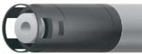
Guidance on interpretation of the SmartQC Score for this sensor is as follows:

Green: Gain and offset are within acceptable limits. Calibration was performed successfully and results are within factory specified limits.

Yellow: The 5 gain is near the threshold of calibration limits. If a user calibration results in a yellow QC Score, perform the following actions:
- Perform a Factory Reset Calibration and re-do the calibration.
- If the sensor had not been properly stored it may be necessary to rehydrate the reference junction, as described in Section 6.13.
- Pre-calibration soaking is advisable for ISEs, especially if a non-green SmartQC Score occurs. Pre-soak the ISE tip in its higher concentration calibration solution for at least 12 hours prior to trying another calibration.
- During calibration, ensure that the standard solutions were thermally equilibrated, meaning that the temperature was stable and not changing during calibration. Sometimes putting the solutions in a water bath can help ensure this.
- Ensure that the standard value was entered correctly.
- It is imperative that the sensors, calibration cup, and sonde guard are all very clean when calibrating.
- Since these modules have a relatively short lifespan, a prior user may have entered an expiration date into the software for when the sensor should be replaced. Check to see if that date is near.
- Ensure that the sensor is free of debris. Refer to Section 6.13 for additional information on how to properly clean the sensor in order to avoid damage.
If the QC Score remains yellow, the sensor is still able to be used, but ISE's are the one case where a yellow-scored sensor should not be used for a continuous deployment, because the period of time before it would become red is probably short. It can be used for spot sampling, and should be recalibrated before each day's use.

Red: The S gain is significantly outside of factory specified limits. If a user calibration results in a red QC Score, follow the same steps described above for a yellow QC Score. If the QC Score remains red, it is likely time to replace the sensor
5.18
NitraLED UV Nitrate
Sensor Overview
The EXO NitraLED UV Nitrate Sensor measures nitrate as nitrogen while compensating for interferences from organic matter in freshwater environments. Refer to the NitraLED Handbook for a complete guide on sensor operation and best practices.

text_image
CAUTION UV LIGHT Do not look directly at the end the of sensor when it is active.Specifications
| Units Measured NO3N (Nitrate-N) in mg/L | |
| Light Source UV LED (x2) | |
| NominalWavelengths | 235 nm,275 nm |
| Pathlength 10 mm | |
| Temperature | |
| Operating | 5 to 35°C |
| Storage | -20 to +80°C |
| Measurement Range ^1 | 0 to 30 mg/L-N |
| MinimumDetection Limit | 0.01 mg/L-N |
| Accuracy ^1 | |
| 0-10 mg/L | ± 0.1 mg/L-N or 5% of reading, w.i.g. (within 2°C)± 0.4 mg/L-N or 5% of reading, w.i.g. (full temp range)± 7% of reading |
| 10-30 mg/L | |
| Response ^2 | T95<30 sec |
| Resolution 0.01 mg/L-N | |
Theory of Operation
UV-nitrate sensors have not supplanted traditional analytical methods such as ion-chromatography for quantitative analysis, but have become common practice as an invaluable screening method due to their inherent advantages of being chemical free and field deployable. Traditional UV photometers use lamps such as xenon, mercury or deuterium which suffer from high power requirements and remain bulky and expensive. However, recent advances in UV-LED technology have made possible truly miniature UV sources which do not suffer the shortcomings of traditional lamps.
YSI's NitraLED employs a UV-LED (center wavelength 235 nm) to generate UV-C optical radiation transmitted across an optical gap of 10 mm where the transmitted optical signal is collected by a UV-enhanced photodiode. The signal is converted to absorbance using the following equation:
Absorbance
$$ \equiv - \log_ {1 0} (I _ {1} / I _ {0}) $$
Where, I_1 is the incident UV radiation and I_2 is the transmitted UV radiation.
Concentration, c, is calculated through the Beer-Lambert Law:
c - Absorbance /eL
Where, is the absorptivity and L is the optical path length.

text_image
Incident Light (Ic) 235 nm Light Source Path Length (L) 10 mm Optical Gap Concentration (c) Molar Absorptivity (ε)Interferences from Non-Intended Attenuating Species
Interference from other non-intended attenuating species needs to be accounted for in any UV absorbance measurement. For YSI's NitraLED, interference correction is loosely adapted from a Standard Method for measuring nitrate in wastewater. As indicated in the method, use of this screening method is primarily intended for uncontaminated natural waters and potable water supplies where natural organic matter (NOM) and turbidity are understood to be the primary sources of optical interference.
The correction is said to be loosely-adapted because this method calls for a nitrate absorbance of 220 nm, but YSI uses 235 nm, and also because this method calls for the filtration of suspended particles (turbidity) but YSI measures turbidity via YSI's EXO Turbidity sensor and applies an internal correction since filtration is impractical for an in situ measurement for most monitoring stations. Utilizing absorption information at 235 nm instead of 220 nm has advantages for this application in that the longer wavelength leaves ample signal "head room" to accommodate for such attenuating species as NOM and turbidity. For example, a concentration of 20 mg/L NO _3 -N (which is considered high) will only use approximately half of the total available signal headroom at a wavelength of 235 nm, but would use practically 100% of the total available signal headroom at 220 nm.
To address interference from natural organic matter, the NitraLED contains an additional 275 nm LED that is introduced into the transmission beam path. The basis of the correction is that both, nitrate and NOM absorb at 235 nm, but only natural organic matter will absorb at 275 nm. This information is used to perform an internal, subtractive correction.
Other Attenuating Species Not Covered in Interference Correction
There are other constituents that absorb in the UV region of the spectrum (e.g. Cl ^+ , Br, HS ^- , I, S 2 O 3^- ) which are known to be a problem in brackish and coastal waters. For other interfering species, those that are not specifically called out in the Standard Method are not addressed for this freshwater-version of the sensor.
Though reported literature values vary significantly for the respective concentrations and absorbances of these seawater constituents ^2 a more pragmatic assessment reveals that users can expect false nitrate readings as high as 0.5 mg/L. For example, YSI deployed sensors into full concentrations (measured salinity of 33 PSU) of Instant Ocean ^ and Gulf of Maine seawater samples which resulted in false nitrate readings of 0.48 mg/L and 0.28 mg/L respectively. Therefore, users should be aware of these unaccounted for interferences if the sensor is to be deployed in saltwater, brackish waters or even in freshwater systems prone to seawater incursions.
For those users who have additional knowledge of the constituent components within a particular water body prone to seawater
Installation on EXO2 / EXO3
These instructions are relevant for NitraLED installation on EXO2 and EXO3 Sondos. The NitraLED Sensor is compatible with EXO1; however, the Sensor Brace and Wiper Brush are not compatible, nor required, for NitraLED use on EXO1.
NOTE: For those with the EXO1 Sonde, it is important to understand the limitations of unattended monitoring without a wiper. Data can be impacted by fouling or even a bubble on the sensor lens, so YSI recommends EXO1 use ONLY under low fouling conditions and short-term deployments or for spot sampling applications. Reference the NitraLED Handbook for more information.
CAUTION: EXO NitraLED emits UV-B/C radiation within the optical cell. Personal protective equipment (PPE) for UV light, including safety glasses and gloves, should be worn when interfacing with a powered sensor.
STEP 1: INSTALL CENTRAL WIPER
The Central Wiper must be removed from the bulkhead to install the new spacer o-ring. Roll the o-ring up the wiper probe until it seats under the wiper brush guard.
Once equipped with the new spacer o-ring, the Central Wiper can be installed on the EXO bulkhead.
STEP 2: INSTALL SENSORS
The NitraLED sensor is unique in that it must be installed in a specific port on the EXO2 and EXO3:
- For EXO2/EXO2 ^i , install the sensor in Port 6
- For EXO3/EXO3 ^2 , install the sensor in Port 4
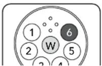
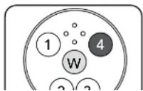
STEP 3: INSTALL SENSOR BRACE
Slide the Sensor Brace, from the NitraLED Sensor Kit [608090] or Sensor Brace Kit [608609], over the sensors. The top of the Sensor Brace should line up with the seam on the brush guard.
NOTE: Make sure the Sensor Brace is seated approximately 0.5 cm below the optical sensor faces.
While holding the Brace in place, carefully pull each of the three larger o-rings over the sensors and fit into the grooves. Once the o-rings are fully seated around the Sensor Brace, installation is complete.
STEP 4: INSTALL NitraLED WIPER BRUSH
Remove old wiper brush by loosening the set screw with a 1/20" hex key. Clean any residue from wiper shaft.
Slide the NitraLED Wiper Brush onto the wiper shaft until fully seated. The wiper shaft has a "D" shape and is sometimes referred to as the D shaft. The wiper brush fits on the D shaft only one way.
DO NOT tighten the set screw yet.
Slowly and gently rotate the Brush counter-clockwise by hand until the NitraLED brush arm is seated within the sensing window of the NitraLED Sensor.
NOTE: Be careful when manually rotating the wiper brush. Quick movements and/or excessive force can damage the wiper motor.
Make sure the NitraLED brush arm is fully contained within the NitraLED sensing window. In this position, tighten the set screw on the UVN Wiper Brush using the 1/16" hex key. After tightening, gently rock the brush to ensure a snug fit against the D shaft and tighten more if necessary.
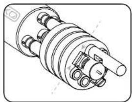
natural_image
Technical line drawing of a mechanical assembly with no visible text or symbols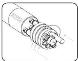
natural_image
Technical line drawing of a mechanical component with no visible text or symbols
text_image
NitraLED Sensor5.19
NitraLED UV Nitrate
Calibration and Site Correction
Review the basic calibration description in Section 5.2.
Before calibrating, be certain that the sensing window is clean (cleaning instructions, Section 6.6).

CAUTION: EXO NitraLED emits UV-B/C radiation within the optical cell. Personal protective equipment (PPE) for UV light, including safety glasses and gloves, should be worn when calibrating.
NOTE: For more guidance on calibration and use of the EXO NitraLED sensor, refer to the NitraLED Handbook.
An EXO Turbidity sensor must be installed during calibration, site correction, deployment of the EXO NitraLED sensor. YSI recommends calibrating the turbidity sensor just before calibrating NitraLED. For best results, users should deploy EXO NitraLED with the same turbidity sensor with which it was calibrated.
| Item No. Description |
| 608072 5 mg/L NO3-N standard |
| 608073 10 mg/L NO3-N standard |
YSI recommends a 2 point calibration at 0 and 5 or 10 mg/L NO3-N using YSI standards:
The standard for Calibration Point #2 should be selected based on which is closer to the expected measurement value. Laboratory prepared NO3-N in Type I water may be used as an alternative to YSI standards. While other standards may be used, such solutions may have interfering species that could result in a calibration that is not optimal for the EXO NitraLED sensor.
Calibration Point #1 at 0 mg/L:
Place the sonde into a clean calibration cup containing Type 1 distilled water with NO added minerals. The software or handheld will show a graph while the sensor is stabilizing. Make sure the "Standard Value" is equal to zero (0). When the Data Stability indicates "Stable" click "Apply" in the software or "Accept Calibration" on the handheld. In the software, select "Add Another Cal
Site-Specific Correction
The NitraLED sensor uses a second LED to compensate for interferences from organic matter. Additionally, the EXO Turbidity sensor (which is required for use) readings are used to correct for turbidity interference. These corrections are class-based using common species for both turbidity and NOM (Natural Organic Matter).
Users may achieve better results with NitraLED by performing an optional site-specific correction using Kor Software. This process will fine tune the NitraLED sensor to compensate for the specific interferences present at the monitoring location.
Collect a Sample and Determine the Nitrate Value
- Obtain a grab sample from the intended deployment site. A least 1 liter is recommended to complete the process.
- Determine the Nitrate of the sample in mg/L NO3-N using an independent and approved method.
Perform a Correction Using Kor Software
NOTE: Make sure both the EXO Turbidity and NitraLED sensors have been recently calibrated before proceeding with the site-specific correction.
- Connect the sonde to Kor Software. Navigate to the Calibration menu and select NitraLED; then select Corrections.
- Enter the Nitrate value in mg/L of the site sample that was determined by independent methods.
- Pour the raw site sample into a beaker or container and use a stir bar and stir plate to keep the sediment suspended.
- With the probe guard installed, insert the EXO sensors in the raw sample and wait for readings to stabilize. Because this raw sample may have significant debris, readings might be continuously moving; however, the values should plateau over time.
- Check the turbidity value. At this stage, users can choose to correct for turbidity based on the raw sample reading or use the default, class-based turbidity coefficients which are pro-programmed in every EXO NitraLED sensor. YSI typically recommends applying corrections based on the raw site sample if turbidity values are greater than 15 FNU.
NOTE: The default class based coefficients may not represent the species of turbidity or NOM for the user's site. Thus even at low turbidity, (less than 15 FNU), the best results may be achieved by performing the full site specific correction.
-
After applying the site-specific or default turbidity correction, remove the sonde from the raw sample, rinse with Type I water, and dry with lint free wipes before moving to the next step.
-
Filter the site sample using a 0.45 μm filter. A vacuum pump or peristaltic pump can be used to expedite this process.
A Place the EXO sensors in the filtered sample
SmartQC for NitraLED Sensors
The SmartQC Score for NitraLED is based on a gain factor and an offset factor. Both of these values may change as the sensor and the optics age,
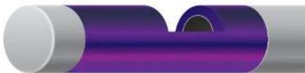
natural_image
Abstract 3D rendering of a purple cylindrical object with a dark circular hole, no text or symbols presentGuidance on interpretation of the SmartQC Score for this sensor is as follows:

Green: Gain and offset are within acceptable limits. Calibration was performed successfully and results are within factory specified limits.

Yellow: The sensor gain or offset is near the threshold of calibration limits. If a user calibration results in a yellow QC Score, perform the following actions:
- Perform a Factory Reset Calibration and complete a recalibration.
a. For calibration point 1, the 0 mg/L NO3-N standard, use Type I water or commercially purchased distilled water with NO minerals added. DO NOT USE commercially purchased Reverse Osmosis, Deionized, or Distilled Water with Minerals added.
b. For calibration point 2, use YSI NitraLED calibration standards 5 mg/L NO3-N [Item# 608072] or 10 mg/L NO3-N [Item# 608073] for best results. These standards are free of the interfering species that would result in a less than optimal calibration.
c. Allow standards to temperature acclimate before calibration. This can minimize bubbles during calibration, especially when the standards are cold and need to warm.
-
Ensure that the standard value was entered correctly.
-
Ensure that the sensor is free of contamination. Refer to Section 6.6 for additional information on how to properly clean the sensor in order to avoid damage.
-
Remove the central wiper brush and thoroughly clean the brush guard. Contaminants can reside within the bristles of the wiper brush and the small gaps of the plastic brush guard.
If the QC Score returns to yellow, the sensor is still able to be used, but the user should monitor this sensor during calibrations for any further drift.

Red: The sensor gain or offset are outside of factory specified limits. If a user calibration results in a red QC Score, follow the same steps described above for a yellow QC Score.

pH and ORP
Sensor Overview
Users can choose between a pH sensor or a combination pH/ORP sensor to measure these parameters. pH describes the acid and base characteristics of water. A pH of 7.0 is neutral; values below 7 are acidic; values above 7 are alkaline. ORP designates the oxidizing-reducing potential of a water sample and is useful for water which contains a high concentration of redox-active species, such as the salts of many metals and strong oxidizing (chlorine) and reducing (sulfite ion) agents. However, ORP is a non-specific measurement—the measured potential is reflective of a combination of the effects of all the dissolved species in the medium. Users should be careful not to overinterpret ORP data unless specific information about the site is known.
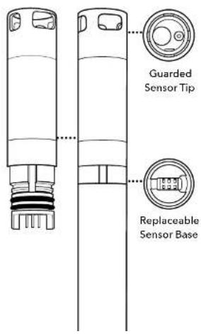
text_image
Guarded Sensor Tip Replaceable Sensor BaseSpecifications
pH
| Units pH units | |
| Temperature | |
| Operating | 5 to +50°C |
| Storage | 0 to 60°C |
| Range 0 to 14 units | |
| Accuracy | ±0.1 pH units within ±10°C of calibration temperature;±0.2 pH units for entire temp range |
| Response T63<3 sec | |
| Resolution 0.01 units | |
| Sensor Type Glass combination electrode | |
ORP
Replaceable Sensor Module
The EXO pH and pH/ORP sensors have a unique design that incorporates a user-replaceable sensor tip (module) and a reusable sensor base that houses the processing electronics, memory, and wet-mate connector. This allows users to reduce the costs associated with pH and pH/ORP sensors by only replacing the relatively inexpensive module periodically and not the more costly base.
The connection of the module to the sensor base is designed for one connection only and the procedure must be conducted in an indoor and dry environment. Once installed the module cannot be removed until you are prepared to replace it with a new module. See Section 6.14 for detailed instructions.
Users must order either a pH or pH/ORP sensor. Once ordered the sensor is only compatible with like-model sensor modules. For example, if a pH sensor is purchased initially, then the user must order a replaceable pH sensor module in the future; it cannot be replaced with a pH/ORP module.
Electrodes
EXO measures pH with two electrodes combined in the same probe: one for hydrogen ions and one as a reference. The sensor is a glass bulb filled with a solution of stable pH (usually 7) and the inside of the glass surface experiences constant binding of H^+ ions. The outside of the bulb is exposed to the sample, where the concentration of hydrogen ions varies. The resulting differential creates a potential read by the meter versus the stable potential of the reference.
The ORP of the media is measured by the difference in potential between an electrode which is relatively chemically inert and a reference electrode. The ORP sensor consists of a platinum button found on the tip of the probe. The potential associated with this metal is read versus the Ag/AgCl reference electrode of the combination sensor that utilizes gelled electrolyte. ORP values are presented in millivolts and are not compensated for temperature.
Signal Quality
Signal conditioning electronics within the pH sensor module improve response, increase stability, and reduce proximal interference during calibration. Amplification (buffering) in the sensor head is used to eliminate any issue of humidity in the front-end circuitry and reduce noise.
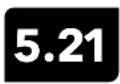
pH Calibration
1-point
Select the 1-point option to calibrate the pH probe using one calibration standard.
NOTE: While a 1-point pH calibration is possible, YSI recommends using a 2 or 3-point calibration for greater accuracy.
2-point
Select the 2-point option to calibrate the pH probe using two calibration standards. In this procedure, the pH sensor is calibrated with a pH 7 buffer and a pH 10 or pH 4 buffer depending upon your environmental water. A 2-point calibration can save time (versus a 3-point calibration) if the pH of the media to be monitored is known to be either basic or acidic.
3-point
Select the 3-point option to calibrate the pH probe using three calibration standards. In this procedure, the pH sensor is calibrated with a pH 7 buffer and both the pH 10 and the pH 4. The 3-point calibration method assures maximum accuracy when the pH of the media to be monitored cannot be anticipated.
Review the basic calibration description in Section 5.2.
Pour the correct amount of pH buffer in a clean and dry or pre-rinsed calibration cup. Carefully immerse the probe end of the sonde into the solution, making sure the sensor's glass bulb is in solution by at least 1 cm. Allow at least 1 minute for temperature equilibration before proceeding.
In the Calibrate menu, select pH or pH/ORP, then select Calibrate.
NOTE: Observe the temperature roading. The actual pH value of all buffers varies with temperature. Enter the correct value from the bottle label for your calibration temperature for maximum accuracy. For example, the pH of one manufacturer's pH 7 Buffer is 7.00 at 25°C, but 7.02 at 20°C.
If no temperature sensor is installed, user can manually update temperature by entering a value.
SmartQC for pH Sensors
The SmartQC Score for pH is based on both a gain and an offset. The offset calculation is based on the millivolts recorded during sensor calibration.
Guidance on interpretation of the SmartQC Score for this sensor is as follows:
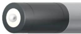

Green: Gain and offset are within acceptable limits. Calibration was performed successfully and results are within factory specified limits.

Yellow: Either the gain or the offset is near the threshold of factory specified limits. If a user calibration results in a yellow QC Score, perform the following actions:
- Ensure that all debris is removed from the surfaces of the sensor. Refer to Section 6.12 for information on proper sensor cleaning in order to avoid damaging the sensor.
- Verify that there are no cracks or visual damage to the glass bulb.
- A yellow score can result from a contaminated standard; ensure that all buffers are clear (not cloudy) and free of debris, and that the calibration cup was clean.
- A Factory Reset Calibration should be performed.
- The electrolyte solution inside the sensor may be partially depleted which causes the millivolt values to drift over the range of calibration. This is not a user-addressable problem, but to prevent it make sure that sensor modules are stored in the same bottle of solution that was shipped with the new modules. Avoid storage of sensor modules in distilled or deionized water.
- If the sensor is new, make sure that there are no air bubbles in the pH bulb. Sensors actually do have air in the reference solution, but if the sensor is in the upright position, as it should be during calibration, an air bubble should not be in the bulb. If air bubbles are found, shake the sensor gently to encourage electrolyte solution to flow into the bulb and the air to rise to the top (where it will not be visible).
- Check the delta slope and mV per decade. Generally, the delta slope should be ≥ 165 mV, and the mV per decade should not deviate by more than 5 units from an ideal of 59.16 (assumes the calibration was performed at or near 25°C). See "Additional Information" below.
If the QC Score returns to yellow, the sensor (or module) is still able to be used but one should be cautious if a long-term deployment is planned. With a yellow QC Score it is more acceptable to use the sensor for discrete sampling because the mV value can be easily monitored under those conditions. In either case, the user should monitor this sensor during calibrations and perform periodic calibration checks for any further drift. Finally, the sensor could be reconditioned by soaking it in a bleach
Additional QC Information for pH
The calibration worksheet provides information that can be useful for assessing performance of the pH modules with age. Two useful parameters shown there are the "delta slope" and the "mV per decade." In general the practice is to not use a pH module where the delta slope is less than 165 mV, and the mV per decade deviates by more than 5 units from an ideal of 59.16. However, these ranges assume a calibration was performed at or near to 25°C. For users who wish to better understand the underlying principles for these guidelines, and perhaps to establish their own acceptance criteria, read on.
The Nernst equation is a well-established relationship that governs pH:
E = E_- + 2.3RT/ F * pH
Where
E = millivolts output
E_v = a constant associated with the reference electrode
T = temperature of measurement in Kelvin
R = the universal gas constant
ηF – the Faraday constant
In simplified y = mx + b form, the relationship is (mV output) = (slope) x (pH) + (intercept). Using this form note that the term 2.3RT/ηF is the slope, and it is sometimes called the Nernst potential.
The absolute value of the Nernst potential, at 298 K (25°C), is 59.16 mV/pH unit. At standard temperature, then, when one would change the pH from 7 to 8, the mV change is expected to be -59.16. Extrapolating further, from pH 7 to pH 10, the mV change would be
3 * -59.16 = -177.3 mV/pH unit.
Similarly, from pH 7 to pH 4 the change would be +177.3 mV/pH unit.
Returning to the Nernst equation, note that these slopes are temperature-dependent. During calibration the mV values for two standard buffer solutions are experimentally established and used by the sonde's software to calculate the slope and intercept of the plot of mV vs. pH. Once this calibration has been performed, the mV output of the probe in any sample can be converted by the sonde into a pH value, as long as the calibration and the reading are carried out at the same temperature.
How can one apply this information for QC?
First, use the temperature compensation to determine what the slope should be for the calibration that was just performed. A calibration performed at 23^ C, for instance, should have a slope of (296/298)^*59.16 , or 58.76. The calibration worksheet shows "mV per decade" between calibration points, such as from 4 to 7 and 7 to 10.
It is not unusual for the mV per decade to deviate from the ideal predicted by the Nernst equation, but typically it should not deviate more than 4 to 5 mV per decade. In this example, if the mV per decade is 56.51, that would be acceptable to most users. If it were instead 53.43, that could be cause for concern.
Another valuable piece of information on the calibration worksheet is in the "Delta slope," which is the change in mV per decade across the range being measured. As stated above, in an ideal scenario at standard temperature, the "delta slope" going from pH 7 to pH 4 would be +177.3, and going from pH 7 to pH 10 it would be -177.3. If, as in our example here, the calibration was performed at 23°C, and therefore the a slope of 58.75 were calculated, then the delta slope from pH 7 to pH 4 would be 3 * 58.75 = 176.25, and the delta slope from pH 7 to pH 10 would be -176.25.
In general it is advisable that the delta slope should not deviate more than about 12-15 from the ideal. So a delta slope for pH 7 to pH 4 of 161 would be considered unacceptable to most users in the present example.
In practice, people don't usually do these calculations, but rather apply a rule of thumb that states, for a laboratory-based calibration where temperature is often near 25^ C, the delta slope should always be ≥165 .
With a better understanding of the Nernst equation, however, users can monitor the changes in the mV per decade and delta slope, and look for big changes from prior calibration worksheets. These changes, even when the SmartOC Score is green, can be useful indicators of changes in the performance of the pH module with age.
ORP Calibration
Review the basic calibration description in Section 5.2.
Pour the correct amount of standard with a known oxidation reduction potential value (we recommend Zobell solution) in a clean and dry or pre-rinsed calibration cup. Carefully immerse the probe end of the sonde into the solution.
In the Calibrate menu, select pH/ORP, then select ORP to Calibrate.
Observe the Pre Calibration Value readings and the Data Stability, and when they are Stable, click Apply to accept this calibration point.
NOTICE: Do not leave sensors in Zebell solution for a long time. A chemical reaction occurs with the copper on the sonde (central wiper assembly, copper tape). While the reaction does not impact calibration, it will degrade the sonde materials over time. Discard the used standard.
Click Complete. View the Calibration Summary screen and QC Score. Click Exit to return to the sensor calibration menu.
Rinse the sonde in tap or purified water and dry the sonde.
Effect of temperature on ORP
The oxidation reduction potential value shows an inverse relationship with temperature. This effect must be accounted for when calibrating the EXO ORP sensor with an ORP standard. YSI recommends using Zobell solution for calibration, but other standards may be used. Refer to the table included with your ORP standard instructions for the mV value that corresponds to the temperature of the standard.
SmartQC for ORP Sensors
The SmartQC Score for ORP is based on an offset from 0 mV.
Guidance on interpretation of the SmartQC Score for this sensor is as follows:

Green: Offset is within acceptable limits. Calibration was performed successfully and results are within factory specified limits.

Yellow: The sensor offset is near the threshold of factory specified limits. If a user calibration results in a yellow QC Score, perform the following actions:
- Perform a Factory Reset Calibration. Complete a recalibration using freshly-prepared Zobell solution. Incorrect mixing of the Zobell solution can cause errors in calibration.
- The electrolyte solution in the sensor may be partially depleted causing shifts to the millivolt readings. This is not a user-addressable problem, but to prevent it make sure that sensor modules are stored in the same bottle of solution that was shipped with the new modules. Avoid storage of sensor modules in distilled or deionized water.
- ORP calibration is temperature-dependent so make sure that the correct standard value was entered, using the instructions that came with the Zobell solution.
- Ensure that the sensor is free of debris. Refer to Section 6.12 for information on proper sensor cleaning in order to avoid damaging the sensor.
If the QC Score returns to yellow, the sensor is still able to be used, but the user should monitor this sensor during calibrations for any further drift. Consideration should be made to eventually replacing the pH/ORP sensor module.

Red: The sensor offset is outside of factory specified limits. If a user calibration results in a red QC Score, follow the same steps described above for a yellow QC Score.
If the QC Score remains red after the Factory Reset Calibration and recalibration, or after replacement of the module and performing a calibration, please contact YSI Technical Support for further assistance.

Rhodamine
Sensor Overview
Rhodamine WT is a fluorescent dye commonly used for time of travel and tracer studies, which provide insight into the hydrological behavior of water bodies. The Rhodamine sensor is a dual-LED fluorescence sensor, featuring one LED for low concentrations and one for higher concentrations. This innovative design allows the sensor to detect very low concentrations of Rhodamine WT while maintaining a wide measurement range.

Specifications
| Units RFU, μg/L | |
| Temperature | |
| Operating | -5 to +50°C |
| Storage | -20 to +80°C |
| Range | 0 to 100 RFU0 to 1,000 μg/L |
| Accuracy ± 5% or 0.1 μg/L w.i.g. | |
| Response T63<2 sec | |
| Resolution | 0.01 RFU0.01 μg/L |
| Linearity r | >0.999 for Rhodamine WT across full range |
| Sensor Type | Optical, fluorescence |

Rhodamine
Calibration
For best performance assure that the sensor face is clean prior to calibration. We advise that new sensors should be calibrated before use, and calibration checks and the user's own tolerance of drift should be used to determine when recalibration is necessary.
YSI does not offer Rhodamine WT standards. Users will prepare their own calibration standards by diluting a 2.5% solution of Rhodamine WT. YSI recommends using Bright Dyes Fluorescent FWT Red 25 – Liquid (item # 106023) from Kingscote Chemicals.
The accuracy of the sensor will be directly influenced by the accuracy of the standard solutions used to calibrate the sensor. Preparation of the following solutions requires precise measurement equipment including graduated pipets and volumetric flasks.
A 4-point calibration procedure is necessary to ensure proper performance over the entire 0–1,000 g/L range of the sensor. The sensor is calibrated to values in g/L. The sensor can also report in units ppb and RFU.
An EXO Conductivity/Temperature sensor must be installed. The effect of temperature on the Rhodamine sensor electronics and the fluorescence of Rhodamine WT can be significant; however, the combination of these two factors is automatically taken into account by the sensor firmware providing temperature compensated readings. This means the "Standard Values" entered during the calibration procedure should match the concentration of the solutions prepared regardless of temperature variance.
Preparation of Rhodamine WT Dye Solutions
Purchase Rhodamine WT as a 2.5% solution to follow the procedure below. Note that there are many types of Rhodamine–make sure Rhodamine WT is selected. If a 2.5% solution cannot be obtained commercially, prepare it from a liquid solution to a 2.5% final concentration, or adjust the dilutions below accordingly. Kingscote Chemicals (Miamisburg, OH, 1-800-394-0678) has historically offered a 2.5% solution (item #106023) that works well with this procedure. It should be stored in the refrigerator when not in use.
NOTE: Preparation of the following solutions requires precise measurement equipment including graduated pipets and volumetric flasks.
STEP 1: Propane a 125 mm/1000 stock solution of Phosphorus WT
STEP 2: Prepare a 25 g/L standard solution* of Rhodamine WT
Depending on the amount (volume) of calibration solution you want to produce, use the following instructions:
For 1,000 mL of 25 μg/L solution:
Transfer 0.2 mL or 200 μL of the 125 mg/L Rhodamine WT base solution into a 1,000 mL volumetric flask. Fill the flask to the 1,000 mL volumetric mark with deionized or distilled water and mix well to produce a standard solution that is 25 μg/L of Rhodamine WT.
For 500 mL of 25 μg/L solution:
Transfer 0.1 mL or 100 μL of the 125 mg/L Rhodamine WT base solution into a 500 mL volumetric flask. Fill the flask to the 500 mL volumetric mark with deionized or distilled water and mix well to produce a standard solution that is 25 μg/L of Rhodamine WT.
*This solution can be stored in the refrigerator (4°C). Its degradation is much more rapid than the base solution and should be used or discarded within 30 days.
STEP 3:
NOTE: The second calibration standard solution* must be at least 125 μg/L, but no more than 1,000 μg/L.
Kor Software will not allow for calibration point #4 outside of the 125-1,000 g/L range. YSI recommends preparing a calibration solution closest to the expected measurement range within these limits.
Refer to the table below to determine the amount of 125 mg/L Rhodamine WT base solution to transfer to a volumetric flask. The columns represent the desired concentration of the standard solution, while the rows represent the desired amount (volume) of standard solution that users would like to produce.
| Concentration | |||||
| 125 μg/L 25 | 0 μg/L 500 μg/L | 1000 μg/L | |||
| Volume | 500 mL 0.5 | mL 1.0 mL 2.0 | mL 4.0 mL | ||
| 1000 mL 1.0 | mL 2.0 mL 4.0 | mL 8.0 mL | |||
Calibration of Rhodamine Sensor
Rhodamine is a dual-LED sensor that requires a 4-point calibration; 2 points for each LED. Calibration point #1 is simply a zero solution (typically DI water). Calibration points #2 and #3 are identical, using the same 25~ g / L Rhodamine WT solution. Calibration point #4 can be any concentration equal to or greater than 125~ g / L , but no more than 1,000~ g / L . For best practices, rinse and dry between standard solutions.
NOTE: Before proceeding with the calibration
• make sure all sensors, guards, and calibration cups are clean
• make sure an EXO Conductivity/Temperature sensor is installed
STEP 1: Calibration Point #1 at 0 g/L
Place the sonde into a clean calibration cup containing distilled or deionized water. The software or handheld will show a graph while the sensor is stabilizing. Make sure the "Standard Value" is equal to zero (0). When the Data Stability indicates "Stable", click "Apply" in the software or "Accept Calibration" on the handheld. In the software, select "Add Another Cal Point" and proceed to Step 2.
STEP 2: Calibration Point #2 at 25 g/L
Place the sonde into a clean calibration cup containing the prepared 25 g/L standard. Make sure the "Standard Value" is equal to 25. When the Data Stability indicates "Stable", click "Apply" in the software or "Accept Calibration" on the handheld. In the software, select "Add Another Cal Point" and proceed to Step 3.
NOTE: Keep the sensors submerged in the 25 g/L standard solution as you proceed to calibration point #3.
STEP 3: Calibration Point #3 at 25 g/L
With the sensors still in the 25 g/L standard solution, make sure the "Standard Value" is still equal to 25. When the Data Stability indicates "Stable", click "Apply" in the software or "Accept Calibration" on the handheld. In the software, select "Add Another Cal Point" and proceed to Step 4.
SmartQC for Rhodamine Sensors
The SmartQC Score for Rhodamine is based on gain factor and an offset factor. Both of these values may change as the sensor and the optics age.
Guidance on interpretation of the SmartQC Score for this sensor is as follows:
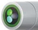

Green: Gain and offset are within acceptable limits. Calibration was performed successfully and results are within factory specified limits.

Yellow: The sensor gain or offset is slightly outside of calibration limits. If a user calibration results in a yellow QC Score, perform the following actions:
- Perform a Factory Reset Calibration and complete a recalibration.
- Ensure that the standard value was entered correctly. Calibration points #2 and #3 must be set at 25 g/L. Calibration point #4 must be set at a minimum of 125 g/L, but no greater than 1,000 g/L.
- Ensure that the sensor is free of contamination. Refer to Section 6.6 for additional information on how to properly clean the sensor in order to avoid damaging the sensor.
If the QC Score returns to yellow, the sensor is still able to be used, but the user should monitor this sensor during calibrations for any further drift.

Red: The sensor gain or offset are significantly outside of factory specified limits. If a user calibration results in a red QC Score, follow the same steps described above for a yellow QC Score.
If the QC Score remains red, please contact YSI Technical Support for further assistance.

Total Algae
Sensor Overview
The Total Algae (TAL) sensors are dual channel fluorescence sensors. The "channels" are for chlorophyll and phycocyanin (TAL-PC), or chlorophyll and phycocerythrin (TAL-PE), which are measured in the water. Each sensor thus yields two data sets: for TAL-PC, one results from a blue-emitting LED that excites chlorophyll (chl) molecules, and the second results from an orange excitation beam that excites the phycocyanin (PC) accessory pigment. The TAL-PE sensor is similar, also having the chlorophyll channel, but rather than an orange-emitting LED there is a slightly blue-shifted beam that excites phycocerythrin (PE).

natural_image
Simple line drawing of a test tube with a circular inset showing two colored dots (no text or symbols)Specifications
| Units | |
| Chlorophyll | RFU, μg/L Chl |
| PC | RFU, μg/L PC |
| PE | RFU, μg/L PE |
| Temperature | |
| Operating | -5 to +50°C |
| Storage | -20 to +80°C |
| Range | Chl: 0-100 RFU, 0-400 μg/L Chl*;PC: 0-100 RFU, 0-100 μg/L*;PE: 0-100 RFU, 0-280 μg/L^ |
| Response T63<2 sec | |
| Resolution | Chl: 0.01 RFU, 0.01 μg/L Chl;PC: 0.01 RFU, 0.01 μg/L;PE: 0.01 RFU, 0.01 μg/L |
| Sensor Type Optical, fluorescence | |
| Linearity | Chl: r^2 >0.999 for serial dilution of Rhodamine WT solution across full range;PC: r^2 >0.999 for serial dilution of Rhodamine WT solution across full range;PE: r^2 >0.999 for serial dilution of Rhodamine WT |
Total Algae Sensor Units
The TAL sensors generate data in RFU or g/L of pigment (chl, PC or PE) units, with RFU as the default. When using either RFU or g/L, the sensor's response is highly linear: a reading of 50 of either unit represents twice as much fluorescence detected as a reading of 25, for example, if the temperature is constant.
However, users are advised to use default RFU, which stands for Relative Fluorescence Units. RFU is used to set sensor output relative to a stable secondary standard, rhodamine WT dye, which normalizes the sensor's output on a 0-100% scale. RFU calibration allows for the best comparisons of data from sensor to sensor, and also enables users to monitor for sensor drift and edaphic factors such as biofouling or declining sensor optical performance over time as the LEDs age. Another reason to use RFU is the excellent linearity once the channels are calibrated with Rhodamine WT, which translates to optimized accuracy of measurements.
The g/L output generates an estimate of pigment concentration that is based upon correlations we built between sensor outputs and extracted pigments from laboratory-grown blue-green algae. Synonymous with parts per billion (ppb), g/L is still in common use by regulatory agencies, but has the drawback that it is very dependent upon the composition of the algal population, the time of day, the physiological health of the algae, and a number of other environmental factors. So if two populations of algae yield a reading of 50 g/L of chlorophyll, it does not mean that those populations are equivalent in the number of cells, for instance. Further, since algal populations can regulate their intracellular pigment concentrations, the g/L of pigment per cell changes with season, time of day, and population dynamics. Thus the challenge with the g/L unit is user expectations: it should not be expected that g/L will necessarily correlate well with pigment extractions that customers perform themselves, and it should not be expected that a doubling of g/L necessarily represents a doubling of the algal population.
RFU is likewise affected by those dynamics: a doubling of RFU does not necessarily mean there has been an exact doubling of an algal population. But it is generally more clear to users that an RFU is detecting a change in relative fluorescence signal, which can occur for a number of reasons in situ.
In any case, many users are required for regulatory compliance to deliver data in g/L, and in waters where the algal populations are fairly predictable or stable from year to year, with respect to species compositions, good correlations can be built. So users are advised to assess whether the pigment concentration delivered by the sensor is reasonable and acceptable for the algal populations and environment with which they work.
That assessment should start with calibration of both RFU and g / L channels with rhodamine WT, as described in the next section. Next, with samples collected from the site of interest, measure both RFU and g / L with the sensor(s). Observing careful handling and preservation of the samples, as soon as possible extract the pigments from the samples, using standardized or preferred methods to determine pigment g / L in each sample. The extraction date may be used to assess how RFU and g / L delivered by the sensor
Measuring cells/mL with EXO TAL Sensors
Similar to g/L, some users have a requirement to report cell/mL data for blue-green alga monitoring, even though in reality these measurements vary widely from algal population to algal population in situ. In Kor Software, there is the capability to have the sonde deliver this unit for the PC and PE channels, based upon user-applied correlations.
When selecting the TAL sensor in the Instruments and Sensors tab of the software, there is a "TAL-PC Phycocyanin Settings" window (or TAL-PE if that is the sensor in use). There are two radio buttons that appear when that window is opened:
• Use legacy cells/mL relationship
• Build my own cells/mL relationship
The first option was designed for users that were accustomed to this unit in our legacy 6-Series sondes, and who want their EXO data to tightly match the cells/mL data generated by these older sondes. The algorithm applied to "match" these outputs across sonde platforms is proprietary, and it is highly advisable that when using this unit at some point users actually test the validity of the outputs for their applications. This can be done by collecting grab samples and comparing actual cells/mL using microscopy or plating as appropriate.
A better method would be to use the second option of building one's own cells/mL relationship. This makes a module appear wherein users can enter an RFU measurement alongside a corresponding cells/mL measurement that has been made for the exact same sample, using microscopy or whatever method the user prefers. The software will derive the relationship between the columns entered by the user and will apply that equation to all subsequent measurements to deliver the cells/mL unit in the sonde's output.
From time to time and place to place, the validity of this correlation can be tested, verified, or validated by collecting grab samples and comparing in vitro measurements of cells/ml, with the in situ values delivered by the sonde. Since every application is different, each user should determine the best method to generate and verify sensor correlations.
In all cases, proper calibration of the sensor with Rhodamine WT is necessary for the most reliable outputs, and for comparison of data from sensor to sensor.

Total Algae
Calibration
For best performance assure that the sensor face is clean prior to calibration. We advise that new sensors should be calibrated before use, and calibration checks and the user's own tolerance of drift should be used to determine when recalibration is necessary.
Users will prepare their own calibration standards. Rhodamine WT is a secondary standard (the actual pigments would be primary standards). It is used because of its stability and affordability. The units that the sensor delivers are in either RFU (recommended) or g / L pigment equivalent units. We strongly recommend using RFU, but in either case Table A below must be used to derive the calibration values that the user will enter during the process outlined below. Use of this table requires a temperature measurement, and the best way to do this is to have an EXO conductivity/temperature sensor on the sonde bulkhead during calibration. In general fluorescence is inversely related with temperature, and this effect will be accounted for to optimize the accuracy of your calibration by using the following table.
| Chlorophyll0.625 mg/L Rhodamine | Phycocyanin0.625 mg/L Rhodamine | Phycoerythrin0.025 mg/L Rhodamine | ||||
| Solution Temperature (°C) | Chl RFU | μg/L chlorophyll | PC RFU | μg/L phycocyanin | PE RFU | μg/L phycoerythrin |
| 30 14.0 56.5 11.4 | 11.4 37.3 104.0 | |||||
| 28 14.6 58.7 13.1 | 13.1 39.1 109.0 | |||||
| 26 15.2 61.3 14.1 | 14.1 41.0 115.0 | |||||
| 24 15.8 63.5 15.0 | 15.0 43.0 120.0 | |||||
| 22 | 16.4 66 16.0 16.0 45.0 126.0 | |||||
| 20 | 17.0 68.4 17.1 17.1 47.0 132.0 | |||||
| 18 17.6 70.8 17.5 | 17.5 | 49.2 138.0 | ||||
| 16 18.3 73.5 19.1 | 19.1 | 51.4 144.0 | ||||
| 14 18.9 76 20.1 | 20.1 | 53.6 150.0 | ||||
Step 1: Prepare Rhodamine WT Dye Solution
Purchase Rhodamine WT as a 2.5% solution to follow the procedure below. Note that there are many types of Rhodamine–make sure Rhodamine WT is selected. If a 2.5% solution cannot be obtained commercially, prepare it from a solid or liquid solution to a 2.5% final concentration, or adjust the dilutions below accordingly. Kingscote Chemicals (Miamisburg, OH, 1-800-394-0678) has historically had a 2.5% solution [item #106023] that works well with this procedure. It should be stored in the refrigerator when not in use.
NOTE: Preparation of the following solutions requires precise measurement equipment including graduated pipets and volumetric flasks.
- For any TAL sensor calibration, prepare a 125 mg/L solution of Rhodamine WT. Transfer 5.0 mL of the 2.5% Rhodamine WT solution into a 1000 mL volumetric flask. Fill the flask to the volumetric mark with deionized or distilled water and mix well to produce a solution that is approximately 125 mg/L of Rhodamine WT. Transfer to a storage bottle and retain it for future use.
*This solution can be stored in the refrigerator (4°C). Its degradation will depend upon light exposure and repeated warming cycles, but solutions used 1-2 times a year can be stored for up to two years. Users should implement their own procedures to safeguard against degradation.
-
For calibration of any chlorophyll channel (on either the TAL-PC or the TAL-PE sensor) and the TAL-PC phycocyanin channel, prepare a 0.625 mg/L solution of Rhodamine WT. Transfer 5.0 mL of the 125 mg/L solution prepared in step one into a 1000 mL volumetric flask. Fill the flask to the volumetric mark with deionized or distilled water. Mix well to obtain a solution that is 0.625 mg/L of Rhodamine WT. Use this solution within 24 hours of preparation and discard it after use.
-
If using a TAL-PE sensor, additionally prepare a 0.025 mg/L solution of Rhodamine WT for calibration of the phycoerythrin channel. Transfer 0.2 mL of the 125 mg/L solution prepared in step one into a 1000 mL volumetric flask. Fill the flask to the volumetric mark with deionized or distilled water. Mix well to obtain a solution that is 0.025 mg/L of Rhodamine WT. Use this solution within 24 hours of preparation and discard it after use.
Step 2: Select the pigment and channel to be calibrated
Step 3: Perform a two-point calibration
Step 3a: Calibration at zero
The zero point is always calibrated first. Place the sonde, loaded with a TAL and an EXO temperature sensor, into a clean calibration cup containing clean water. It is not required that this be deionized or even distilled water; it must be free of any particles that might fluoresce and interfere with the calibration process. Thus distilled water is typically what users prefer to have that assurance.
The software or handheld will show a graph while the sensor is stabilizing, and the temperature will also be shown. Temperature is not needed for the zero point; the user must enter a "Standard Value" of 0. When the Data Stability indicates "Stable", click to "Apply" the calibration. Next select "Add Another Cal Point" and proceed to Step 3b.
Step 3b: Calibration with Rhodamine WT
The same basic procedure will be followed, but using Kor Software, Kor Mobile, or the EXO Handheld will require that users enter the temperature-compensated standard value for the calibration solution. In all cases, the reading from the EXO Conductivity/ Temperature sensor is the most reliable to use, and the value for the standard can be derived from the Table A provided above.
As an example, assume that you will calibrate the chlorophyll RFU channel, and that the temperature measured in the 0.625 mg/L rhodamine WT solution is 22°C. This temperature will show up on the calibration screens using the Kor Software, and can be seen on the handheld's dashboard screen as well. The first standard value entered during calibration will be 0, since that standard will be water (see Step 3 below). The second standard value will be 16.4, as derived from Table A using a temperature of 22°C. Alternatively, if you intend to use the μg/L unit, the second standard value would be 66 for this example. Using the same 0.625 mg/L rhodamine WT solution to calibrate the PC channel will yield a second standard value of 16.0 RFU or 16 μg/L. You will enter these values when you perform the calibration.
Upon entering the Table A-derived value, wait for the sensor to show "Stable" and then click on "Apply". Now choose "Complete Calibration" and then "Exit."
Note that throughout this process users had options to "Redo a cal point" or to "View Calibration Worksheet." So for any channel and a given unit of interest, a point can be redone at any time without having to exit out to the beginning of the process.
However, to now calibrate other units for either the same or different pigment channels, this process must be started again at Step 2.
Re-zeroing the TAL Sensor
Oftentimes users will perform a "cal check" in water to assess if the sensor has drifted beyond an acceptable limit defined by that user. When drift has occurred ideally a two-point calibration should be performed. However, when there isn't an opportunity to prepare the rhodamine solutions and perform a two-point calibration, or if users are mainly interested in accuracy at the lower end of the sensor's range, they may choose to re-zero the sensor.
Historically referred to as a "single-point calibration," doing a calibration with water only resets the zero value, called here "re-zeroing" the sensor. The main advantage of doing this is speed, and users should be aware that re-zeroing the sensor does not reset the second point entered during the most recent two-point calibration. The consequence is that drift error will be alleviated at and near zero, but more error can accumulate in the measurement the farther away from zero the measured value is. The amount of that error can be different from sensor to sensor, and use case to use case. It is dependent upon how much that second point may drift, which is not always equivalent to how much the zero point drifts.
For many users, especially those with sites where pigment is rarely detected and values are at or near zero most of the time, the far-from-zero accumulation of error is a non-issue. For others, a single point calibration may not be acceptable. A single-point calibration is an option in the software and is performed exactly the same way as the two-point calibration, using water as the standard and waiting for the value to stabilize before applying it. Rather than adding a second calibration point, the user would exit after the water calibration.
SmartQC for TAL Sensors
The SmartQC Score for any TAL sensor is based on an offset from 0 RFU, and a gain factor. Each individual channel (Chlorophyll, Phycocyanin, Phycoerythrin) has a unique offset and gain factor. It is possible to have a green SmartQC Score for calibration of one channel, but a yellow or red SmartQC Score for the second channel. In this case the TAL sensor SmartQC
that is shown in Kor Software will appear as the worst QC Score (yellow or red), and one must look at the individual channels to investigate where the issue is. Thus the steps outlined here are for each channel, and for each unit calibrated within that channel.
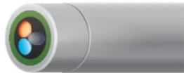
Guidance on interpretation of the SmartQC Score for this sensor is as follows:

Green: Gain and offset are within acceptable limits. Calibration was performed successfully and results are within factory specified limits.

Turbidity
Sensor Overview
Turbidity is the indirect measurement of the suspended solid concentration in water and is typically determined by shining a light beam into the sample solution and then measuring the light that is scattered off of the suspended particles. Turbidity is an important water quality parameter and is a fundamental tool for monitoring environmental changes due to events like weather-induced runoff or illicit discharges. The source of the suspended solids varies (examples include silt, clay, sand, algae, and organic matter) but all particles will impact light transmittance and result in a turbidity signal.

Specifications
| Default Units FNU | |
| Temperature | |
| Operating | -5 to +50°C |
| Storage | -20 to +80°C |
| Range 0 to 4000 | FNU |
| Accuracy | 0-999 FNU: 0.3 FNU or ±2% of reading, whichever is greater;1000-4000 FNU: ±5% of reading ^2 |
| Response T63<2 sec | |
| Resolution | 0-999 FNU: 0.01 FNU1000-4000 FNU: 0.1 FNU |
| Sensor Type Optical, 90° scatter | |
| Optics:Excitation | 860±15 nm |
1 ASTM D7315-07a "Test Method for Determination of Turbidity Above 1 Turbidity Unit (TU) in Static Mode."
The EXO Turbidity sensor employs a near-infrared light source and has been characterized as a nephelometric near-IR, non-ratiometric sensor in accordance with ASTM Method D7315-07a. This method calls for this sensor type to report values in formazin nephelometric units (FNU), which is the default calibration unit for the EXO sensor. Users are able to change calibration units to nephelometric turbidity units (NTU). The EXO Turbidity sensor values in FNU and NTU units are equivalent; changing the reported unit does not alter the measured value.
Turbidity is one of the most misunderstood measurements in environmental monitoring. In reality the turbidity sensor is not much different from other optical sensors: differences in outcomes with different standards, sensors and environments can be a result of differing optical components and geometries, and the impact of different environmental factors upon the measurement technologies themselves. Thus like many optical measurements, where a light beam is passing through a sample in an environment of changing temperature, etc., turbidity is best monitored with consistent use of standards, technology platforms, and practices to compare outcomes for scientific conclusions.
Among the many factors that can impact turbidity measurements, users should be aware of three over which they have some control. These are the use of recommended YSI standards, preventing fouling, and using sound and consistent calibration practices.
Turbidity Standards
Turbidity sensors of many types, from many manufacturers, are often calibrated with formazin. Considered the "gold standard" for turbidity calibration there is the perception that all turbidity sensors will read consistently in formazin. In practice this has led to the belief that two different sensors of different types (design or manufacturer, for instance), if calibrated in formazin, would yield the same FNU when used to measure a sample. When sensors are of the same fundamental design, using the same type of light source and with detection of scattering at the same angles of incident light, this is more likely to be true, especially if measuring an actual formazin solution. However, with field samples this rule does not always hold; different manufacturer's sensors calibrated with the same formazin solutions can yield slightly different readings from the same field samples. There can be a number of reasons for this, including how the raw data are post-processed.
Due to the challenges of preparation and disposal of formazin, polymer-based standards are now preferred as turbidity standards. As with formazin, it is the case that field readings will vary between different models of turbidity sensors even when they are calibrated with the same standards. This is true of the popular AMCO-AEPA standards upon which YSI's standards solutions are based, and which were used to determine the Specifications shown below.
Further, if YSI sensors are calibrated with the non-YSI standard AMCO-AEPA solutions, sensor specifications may differ from those
Preventing Fouling
Turbidity measurements are vulnerable to both biofouling and non-biological fouling. This is because of the high sensitivity and resolution of measurements, which can be affected by any changes to the sensor face that light must pass through. Any obstruction of that light path will affect measurements, and even bubbles on the sensor's face can affect measurements. Low-range measurements (e.g. <100 FNU) are especially susceptible to these effects.
As such it is imperative in continuous monitoring applications that anti-fouling tools be employed. The Central Wiper used with the EXO2, EXO2 ^5 , EXO3, and EXO3 ^5 sondes is highly effective in combating fouling during continuous monitoring, and can be aided by strategies like C-spray and copper tape on the sensors. Even during spot-sampling applications such as with EXO1 and EXO1 ^5 it is very important that users pay attention to the sensor faces so that they are not trapping bubbles during measurements.
Calibration Practices
The following section describes in detail how to calibrate EXO turbidity sensors. Before calibrating, be certain that the probe is very clean and free of debris. Solid particles, particularly those carried over from past deployments, will contaminate the standards and can cause either calibration errors and thereby errors in measurement.
The cleaning instructions in Section 6.6 should be helpful for preventing contamination, but another recommendation we make is to have a sonde guard and a calibration cup devoted solely to turbidity calibration.
Finally, never calibrate turbidity without the sonde guard. The sonde guard ensures the minimum pathlength for turbidity measurement. If one is using the copper anti-fouling guard for a deployment, then that is the guard that should be used during turbidity calibration (don't use the standard black guard).
Note that the level of patina on your copper guard may affect the turbidity readings. Calibrate turbidity using the copper guard used for deployment, but make sure it is clean.

Turbidity
Calibration
Tools and Practices
YSI Turbidity standards that are based upon AMCO-AEPA polymer are the basis of SmartQC and EXO turbidity sensor specifications, and therefore should be used for turbidity sensor calibration. Gallon bottles are available as follows:
| Item No. | Description |
| 608000 | 0 FNU |
| 607200 | 12.4 FNU |
| 607300 | 124 FNU |
| 607400 | 1010 FNU |
Standards should be selected based upon the range in which one is expected to work. For low-turbidity waters, one might use 0 and 12.4 for a two-point calibration. If turbidities might exceed the lower ranges 0 and 124 should be used for a two-point calibration (not 0 and 1010 for reasons described below), and 0, 124 and 1010 for a three-point calibration. There is not a calibration standard beyond 1010 FNU at this time.
The FNU of each bottle can change with production batches, and as such the label of the bottle should always be checked for the FNU that should be entered into the software or handheld during calibration.
In some cases it may be acceptable to use deionized or distilled water rather than YSI's 0 FNU standard. Beware, however, that distilled water from some sources has been shown to not be 0 FNU. Calibration with a non-zero standard can cause negative readings when the sensor is used in waters that actually are clear. Non-zero readings also can occur if the calibration equipment (e.g. sonde guard, calibration cup) is not sufficiently clean.
Some users will have a preference, if not a requirement, for use of formazin standards. Examples may be formazin prepared according to Standard Methods for the Treatment of Water and Wastewater (Section 2130 B), or Hach StablCal™ of various NTUs. These standards are acceptable for a two-point calibration. However, users who anticipate working in higher turbidities and who choose to use a formazin standard for the third point may see yellow SmartQC Scores during that calibration. The sensor can still be used, but since the algorithms for calibration were developed with Y5I's polymer beads there may be less perfect alignment of the gain factors when using formazin.
Performing a 2-point calibration
Pour the 0 FNU standard (or deionized or distilled water) into the clean calibration cup and immerse the probe end of the sonde into the standard. The sonde should have the sonde guard on, and if one will deploy with the copper anti-fouling guard that is likewise the guard that should be used during calibration. Pay careful attention while submersing the sensors to not trap bubbles on the face of the turbidity sensor(s).
In either Kor Software or the handheld's Calibration menu, select Turbidity to calibrate.
Enter 0.0 (or some offset value between 0.0 and 1.0) as the first calibration value. While the sensor is still stabilizing one may wipe the sensors (using the button in the software or menu option on the handheld) to remove any bubbles. When the data are Stable, select the option to "Apply calibration" for this point.
It is advised at this point that the sensors, sonde guard, and calibration cup be rinsed with a small amount of the standard that will be used for the second calibration point. Discard this rinse, and then fill the cup with the second calibration standard. Click Add Another Cal Point in the software.
Place the sensors into the second calibration standard, and follow the same steps to wipe and obtain a stable reading. Use the value on the label of the YSI standard bottle for the FNU of the second calibration point.
When the data are Stable, select the option to "Apply calibration" for this point. Select the option to complete the calibration and observe the SmartQC Score in the calibration worksheet. In Kor Software, color indicators will also make the QC Score apparent.
Rinse the sonde with water and discard all used turbidity standards.
Performing a 3-point calibration
The steps for a three-point calibration are the same as describe above, but note that:
- The first point must always be 0 FNU, followed by the second standard (5-200 FNU) and then third (400-4200 FNU).
• Always use the same type of standard for the two non-zero points. Both must be YSI polymer, or both must be formazin. - It is critically important, between the second and third calibration points, to rinse the sensors, sonde guard, and calibration cup with water, blot them dry with a lint-free material, and then do a rinse (at least once) with the standard for the third calibration point.
SmartQC for Turbidity Sensors
The turbidity response is nonlinear across the sensor's range, and a proprietary algorithm that employs up to five terms is used during calibration and for generation of the SmartOC Score. Three of those terms are the actual calibration points, and those calibration points must read within an absolute range set within the sensor (this is slightly different than the concept of an
offset that is used for SmartQC on most sensors). Two of the terms are calculated from the ratios of the calibration points, and likewise must be within an absolute range set within the sensor. The result is that the SmartQC calculation for turbidity is slightly different depending upon whether one does a 1, 2, or 3 point calibration. Since each individual term used by the algorithm must fall within an absolute range SmartQC is most reliable when the YSI standards, upon which these algorithms were built, are used.
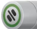
Guidance on interpretation of the SmartQC Score for this sensor is as follows:

Green: A green SmartQC Score means that the point for a single-point calibration is within the specified range. For a two-point calibration a green SmartQC Score means that both calibration points, as well as the slope between them, is within the specified range for each term. For a three-point calibration a Green SmartQC Score means that all three calibration points, as well as the slope between the first two points and the slope between the second two points, are within the specified ranges for each term.

Yellow: A yellow SmartQC Score can result if any one of the five terms of interest is outside of the factory-specified range. If a user calibration results in a yellow QC Score, perform the following actions:
- Perform a Factory Reset Calibration and re-do the calibration.
- If a two-point calibration was performed, make sure that the second point is between 5-200 FNU.
- If a three point calibration was performed with formazin, make sure that each calibration point was within the specified ranges of 0-1 FNU, 5-200 FNU, and 400-4200 FNU.
- If a three point calibration was performed with YSI's polymer standards, make sure the correct values from the bottles were entered during calibration. For example, make sure the EXO values, and not the 6-Series values, were entered from the label.
- Make sure you are using YSI's polymer standards. Difficulties in calibration may occur if AMCO-AEPA standards that were not produced for YSI instruments are used. These will not have a YSI label on them.
- It is imperative that the sensors, calibration cup, and sonde guard are all very clean when calibrating turbidity.
- Customers who use the 12.4 NTU standard to calibrate will often see a yellow QC Score, even with a perfect calibration.
- Always use an EXO calibration cup and EXO probe guard with bottom plate during the turbidity calibration.

Total Suspended Solids
Calculation
Please follow the process below to calculate TSS,
NOTE: This process cannot be performed via the EXO handheld. It must be done using Kor Software.
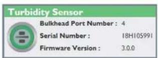
Step 1
Make sure the turbidity probe is installed in the sonde.
Step 2
In Kor Software, connect to the sonde, and navigate to Instrument and Sensors>Turbidity. The correlation table appears under the Turbidity Settings header.
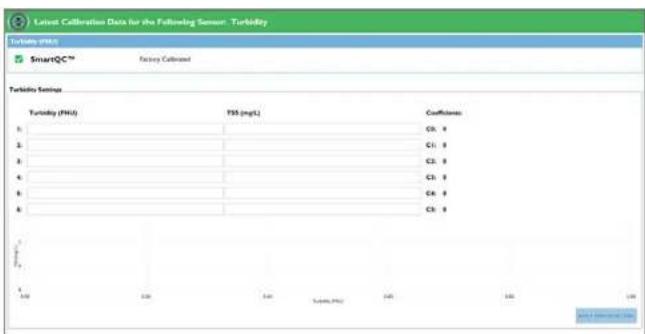
text_image
Latest Calibration Data for the Following Sensor: Turbidity Turbidity (FUU) 500 500 500 500 500 500 500 500 500 500 500 500 500 500 500 500 500 500 500 500 500 500 500 500 500 500Step 3
Type in the turbidity NTU/FNU values and the corresponding TSS
The following table provides the basic concepts of the theory of the algebraic structure.

text_image
Are You Sure? Are you sure you would like to apply the configuration settings? Applying incorrect configuration settings may result in inaccurate sensor data. YES NO Success The following coefficients were applied to the sensor: C0: -39.9999999999701 C1: 0.49999999998457 C2: 2.87989425420495E-14 C3: -2.53466133601138E-16 C4: 1.07214151836942E-18 C5: -1.76242441376105E-21 OKStep 4
The message below will be displayed, asking for confirmation that the settings should be applied. Click Yes.
Step 5
A message box appears which states that the coefficients have been successfully applied to the sensor. The coefficients are also displayed.
Step 6
TSS values will now be displayed on the Dashboard based on the values entered via Kor and saved to the turbidity probe.
Step 7
If the TSS parameter is not displayed on the Dashboard, go to File>Settings>Turbidity, and click the "-" sign next to TSS Disabled to activate the TSS parameter. A "+" sign will appear and TSS Enabled will be displayed. Click Save and return to the Dashboard.
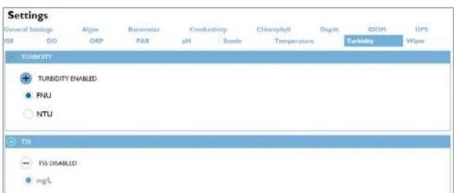
text_image
Settings General Settings Algae Banometer Conductivity Chamnophyll Depth RDOH GPS ISE DO ORF PAR pH Sonds Temperature Turbidity Wiper TURBIDITY + TURBIDITY ENABLED ● FNU ○ NTU TSI - TSS DISABLED ● mg/L
text_image
01/08/19 09:36:14AM Turbidity Display None TSS mg/l TSS g/LStep 8
The units to display TSS will need to be activated separately in the EXO handheld. To add the TSS parameter to the handheld, navigate to Handheld>Display>Units>Turbidity>TSS and choose which unit to display. Click "Esc" to return to the live data dashboard. TSS will be displayed.
If you wish to view the TSS coefficients in the handheld, navigate to Calibration>Turbidity>Setup and the TSS coefficients will be displayed.

text_image
01/08/19 09:38:31AM Dashboard Log One Sample 23.257 °C 730.4 mmHg 86.0 DO % 7.34 DO mg 0.1 SPC μS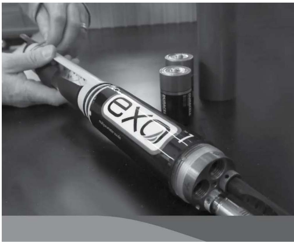
natural_image
Close-up of a hand holding a EXO fuel injector with two batteries nearby (no visible text or symbols on the main subject)6.1
Sonde
Storage

EXO Maintenance
Watch Videos Now
Proper sonde storage helps to ensure proper sonde operation. To keep sondes in their best working order, users must follow these instructions. This section will identify storage as "long-term" or "short-term." Long-term denotes storage during times of long inactivity (over winter, end of monitoring season, etc.). Short-term denotes storage during times the sonde will be used at a regular interval (daily, weekly, biweekly, etc.).
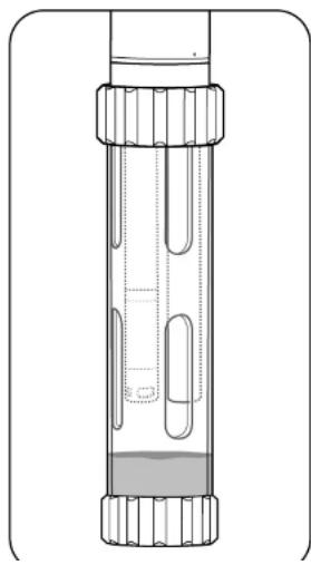
natural_image
Technical line drawing of a cylindrical mechanical component with flanged ends and internal cutouts (no text or symbols)1 Short-term storage
For interim storage, users should keep sensors moist, but not submerged; submersion during storage may produce sensor drift. Users should aim for a storage environment of water-saturated air (100% humidity) for the sensors.
Place approximately 0.5 in (1 cm) of tap or environmental water in the bottom of the calibration cup. Do not use deionized or distilled water because it can damage pH sensors and ISEs if installed. Then place the sonde with all of its sensors into the cup and close it tightly to prevent evaporation. Users can also use a moist sponge to create a humid environment.
Ensure that unused sensor ports are properly protected with port plugs. The sonde itself should be stored in dry air.
To protect the cable connector, either leave the cable installed on the connector, or install the port plug. This is especially important for sondes with level; users should always keep the cable connector of vented sondes dry. (See Section 8.5)

Sonde Maintenance
Like all precision equipment, EXO sondes work most reliably when users maintain them properly. A proper inspection and cleaning can prevent several issues, including leaks. When performing general maintenance on the sonde, also check this manual's depth and connector sections. Use only the recommended materials to service instruments. Each sonde comes with a maintenance kit, including proper lubricants and replacement o-rings. Users can order replacement o-ring kits [part #599680 or 599681] or tool kit [599594] from the manufacturer or an authorized distributor.

text_image
Diagram of a flashlight with warning symbol and magnified detail view1 Inspect and service o-rings
User-serviceable o-rings are located in the EXO sonde battery compartments. Perform a thorough visual inspection of o-rings each time they are exposed. Carefully look for grit, hair, etc. on the o-ring and mating surfaces and wipe away any contamination with a lint-free cloth. Without removing them from their grooves, lightly grease each o-ring with silicone lubricant. Replace any damaged o-rings.
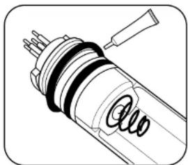
natural_image
Technical line drawing of a mechanical component with no visible text or symbols2 Replace o-rings
If the above inspection reveals a damaged (split, cracked, or misshapen) o-ring, remove it. Wipe the groove clean with alcohol and a lint-free cloth. Grease the o-ring by drawing it between your lightly greased thumb and index fingers. Place the o-ring in its groove, being careful to not roll or twist it, and lightly grease the surface. Inspect the o-ring for contamination.
NOTICE: Do not apply excess grease to the o-rings. This can cause contamination and scal failure.
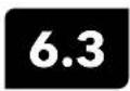
Sonde
Replace EXO1 Sonde Bail
Sonde bails provide users with a handle for convenient transport and an attachment point for cable strain reliefs. If an EXO1 bail breaks due to impact or standard wear and tear throughout the life of the sonde, a user can easily replace it. We also recommend attaching the cable's strain relief mechanism to the bail.

natural_image
Diagram of a mechanical tool or device with directional arrows indicating movement (no text or symbols)1 Remove battery cover
Twist the battery cover counterclockwise until free. Then slide off the battery cover.
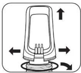
natural_image
Diagram of a mechanical device with directional arrows indicating rotation or movement (no text or symbols)2 Remove bail
Spread the sides of the bail away from the connector, pull the bail over the posts on top of the sonde, and remove the o-ring from its groove and discard.

Sonde
Replace EXO2 and EXO3 Sonde Bail
Sonde bails provide users with a handle for convenient transport and an attachment point for cable strain reliefs. If an EXO2 or EXO3 bail breaks due to impact or standard wear and tear throughout the life of the sonde, a user can easily replace it. We also recommend attaching the cable's strain relief mechanism to the bail.
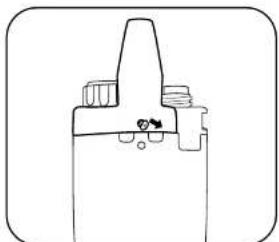
natural_image
Pure mechanical component diagram without any text, numbers, or symbols1 Remove bail
Use a small screwdriver to remove two screws on the sides of the bail.
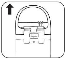
natural_image
Pure mechanical cross-section diagram without any text, numbers, or symbolsOnce screws are removed, lift the bail off the sonde.
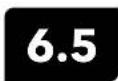
Depth and Level Sensor
Maintenance and Storage
EXO depth and level sensors access the water through small holes (ports) located in the sonde body or bulkhead. Although users cannot access them directly, proper storage and maintenance will help to ensure reliable operation. Depth sensors can be stored dry, in water-saturated air, or submerged in clean water. However, be sure that the water does not contain solutions that are corrosive. This can cause damage to the sensor's strain gauge.

text_image
EXO1 EXO2/FXO31 Locate depth ports
The two EXO1/EXO1 ^5 depth ports are located above the EXO label. The EXO2/EXO2 ^5 /EXO3/EXO3 ^5 depth ports are located on the metal bulkhead face itself, in the largest open area between ports.
2 Clean depth ports
Although users cannot directly access the depth/level sensors, they should periodically clean them with the syringe included in the EXO tool kit [599594]. Fill the syringe with clean water and gently force water through one of the ports. Ensure that water flows from the other hole. Continue flushing the port until the water comes out clean.
NOTICE: Do not insert objects in the depth ports, as this may cause damage to the transducer not covered under the warranty.
3 Level sensor storage
Users can store these sensors either dry or submerged in clean water. However,

Standard Optical Sensors
Maintenance and Storage
Standard optical sensors include Turbidity, Total Algae, fDOM, Rhodamine, and NitraLED sensors; these optical sensors are very low maintenance. This section identifies storage as "long-term" or "short-term." Long-term denotes storage during times of long inactivity (over winter, end of monitoring season, etc.). Short-term denotes storage during times the sonde will be used at a regular interval (daily, weekly, biweekly, etc.).
NOTE: It is important to make sure the sensor connector is lubricated prior to installation. Maintain connectors as instructed in Section 6.17.
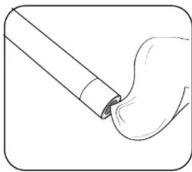
natural_image
Simple line drawing of a brush applying paint to a curved surface (no text or symbols)1 Clean sensing window
Optical sensors require minimal maintenance. Users should periodically inspect the optical surface at the tip of the sensor and wipe it clean with a non-abrasive, lint-free cloth if necessary. As much as possible, prevent scratches and damage to the sensing window.
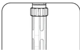
natural_image
Pure diagram of a cylindrical object with internal structure, no text or symbols present2 Long- and short-term storage
Optical sensors require minimal precautions. Users can either remove the sensors or leave them installed in the sonde for long- and short-term storage. If left installed on the sonde, follow guidelines for sonde storage. If users remove them from the sonde, the sensors may be stored in dry air in their shipping cap (to protect against physical damage).
6.7
Conductivity / Temperature Sensor
Maintenance and Storage
EXO Conductivity and Temperature (C/T) sensors require little maintenance or special attention for storage. As much as possible, prevent impact to the sensor's exposed thermistor. This section will identify storage as "long-term" or "short-term." Long-term denotes storage during times of long inactivity (over-wintering, end of monitoring season, etc.). Short-term denotes storage during times the sonde will be used at a regular interval (daily, weekly, biweekly, etc.).
NOTE: It is important to make sure the sensor connection is lubricated prior to installation. Maintain connectors as instructed in Section 6.17.

natural_image
Simple line drawing of a cylindrical object with a downward arrow and a textured base (no text or symbols)1 Clean electrode channels
The only parts of the C/T sensor that require special maintenance are the channels leading to the internal electrodes. Dip the sensor's cleaning brush (included in the sonde maintenance kit) in clean water, insert at top of channels, and sweep the channels 15-20 times. If deposits have formed on the electrodes, use a mild solution of dish soap and water to brush the channels. If necessary, soak in white vinegar to aid cleaning. Rinse the channels with clean water following the sweepings or soak.

natural_image
Simple line drawing of a cylindrical object with a flanged top and side grooves (no text or symbols)2 Short-term storage
When in regular field use, the sensor should remain installed on the sonde in an environment of water-saturated air. Place approximately 0.5 in (1 cm) of tap or environmental water in the bottom of the calibration cup. Do not use deionized or distilled water because it can damage pH sensors and ISEs if installed. Insert the ponds into the cup and account it on tickby to prevent gas extraction (Mare

Dissolved Oxygen Sensor Storage
EXO DO sensors require separate storage instructions from other optical sensors due to their sensing membranes. This section will identify storage as "long-term" or "short-term." Long-term denotes storage during times of long inactivity (over winter, end of monitoring season, etc.). Short-term denotes storage during times the sonde will be used at a regular interval (daily, weekly, biweekly, etc.).
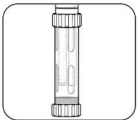
natural_image
Illustration of a laboratory test tube with stoppers and tubing (no text or labels)1 Short-term storage
When in regular field use, the DO sensor should remain installed on the sonde. Place approximately 0.5 in (1 cm) of tap or environmental water in the bottom of the calibration cup. Do not use deionized or distilled water because it can damage pH sensors and ISEs if installed. Insert the sonde into the cup and screw it on tightly to prevent evaporation. (More information in "Short-Term Sonde Storage" Section 6.1.)
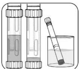
natural_image
Illustration of two test tubes and a beaker with liquid, no text or symbols present2 Long-term storage
If pH sensors and ISEs have been removed, the DO sensor can be left installed in the sonde and submerged in clean water in the calibration cup. Screw the cup on tightly to prevent evaporation. Users may also store the DO sensor by itself in two ways. One, submerge the sensing end of the sensor in a container of water; occasionally check the level of the water to ensure that it does not evaporate. Two, store the sensor in water-saturated air.
We do not recommend storing the sensor with the connector end unmated or

Dissolved Oxygen Sensor
Maintenance and Rehydration
EXO optical Dissolved Oxygen (DO) sensors require unique maintenance instructions due to their sensing membranes. Users should routinely perform these steps in order to achieve the highest levels of sensor accuracy. DO sensor caps have a typical life of 12 months. After this point, users should replace the DO membrane cap. As caps age, accuracy may be reduced, ambient light rejection suffers, and response times can be affected.
NOTE: It is important to make sure the sensor connector is lubricated prior to installation. Maintain connectors as instructed in Section 6.17.
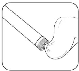
natural_image
Illustration of a tool interacting with a curved object, no text or symbols present1 DO membrane maintenance
Users should periodically inspect the optical surface at the tip of the sensor and wipe it clean with a non-abrasive, lint-free cloth if necessary. Never use organic solvents to clean an EXO DO sensor.
As much as possible, prevent scratches and damage to the sapphire sensing window. Avoid getting fingerprints on the window. If necessary, wash with warm water and dish soap and rinse with DI water.
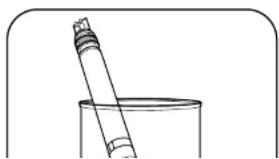
natural_image
Simple line drawing of a pipette and a beaker in a container (no text or symbols)2 Sensor rehydration
Users should always store DO sensors in a moist or wet environment in order to prevent sensor drift. However, should DO sensors be left in dry air for longer than eight hours, they must be rehydrated. To rehydrate, soak the DO sensor cap in warm (room temperature) tap water for approximately 24 hours. Following this

Dissolved Oxygen Sensor
Sensor Cap Replacement
Follow these instructions to replace the sensor cap on an EXO optical Dissolved Oxygen sensor once the previous cap has exhausted its usable life (typically about one year). The DO sensor cap [part #599110-01] is shipped in a humidified container, and should be stored in a 100% humid environment.
NOTE: Keep the instruction sheet shipped with the DO sensor cap as it contains the unique coefficients required for calibration. If the sensor cap dries completely, follow instructions to rehydrate it.

natural_image
Diagram of a cylindrical pipe with a textured inner layer and black arrows indicating direction (no text or symbols)1 Remove current sensor cap
Rotate the sensor cap with your fingers counterclockwise until free.
If possible, do not use any tools during this process. However, should the cap be immovable after use, carefully twist the sensor cap with pliers until it breaks loose.
NOTICE: Do not use pliers on the sensor body, and take great care not to damage the sensor threads.
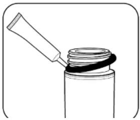
natural_image
Simple line drawing of a mechanical component with a handle and ring (no text or symbols)2 Replace o-ring
Without using tools, remove the previous o-ring (pinch the o-ring out, then roll it upwards over the threads) and discard it. Clean the o-ring groove with a lint-free cloth to make sure it is free of debris. Visually inspect the new o-ring for nicks, tears, contaminants, or particles; discard damaged o-rings. Without twisting it, carefully install the new o-ring over the threads and into its groove, then apply a thin coat of silicone lubricant to the o-ring only.
4 Configure sonde for new cap
Connect the sonde to Kor and navigate to the Instrument and Sensors tab. Select the DO sensor.

text_image
Latest Calibration Data for the Following Sensor: DO DO (S.CR) SmartQC™ Factory Calibrated DO (mg/L) SmartQC™ Factory Calibrated DO (lb max) SmartQC™ Factory Calibrated Sensor Cap Settings Data Lost Updated : 328/01/14 K1 : C#1/C#N7 K5 : S#1/BEA6 K2 : #C#PANC K6 : IC#74C03 K3 : #HA5DE K7 : DM421CE K4 : #HDAAB KC : BF DO Gain : Csp SN : 22E19174 APPLY ERROR ITEMSIn the DO screen, enter the unique membrane cap coefficients found on the instruction sheet shipped with the DO sensor cap. Click Apply Sensor Settings to save the changes.
5 Store sensor cap
Using Kor Software, calibrate the sensor with the new calibration coefficients.
NOTE: The Cap SN will updated after the user disconnects and reconnects the sonde to Kor Software.
NOTE: Calibration coefficients are associated with specific individual sensor ranges
6.11 pH and pH/ORP Sensors Storage and Rehydration
pH and pH/ORP sensors have two specific storage requirements: they should not be stored in distilled or deionized water and their reference electrode junction should never dry out. This section will identify storage as "long-term" or "short-term." Long-term denotes storage during times of long inactivity (over-wintering, end of monitoring season, etc.). Short-term denotes storage during times the sonde will be used at a regular interval (daily, weekly, biweekly, etc.).

natural_image
Illustration of a laboratory test tube with liquid and stoppers (no text or labels)1 Short-term storage
When in regular field use, the sensor should remain installed on the sonde in an environment of water-saturated air. Place approximately 0.5 in (1 cm) of tap or environmental water (not deionized or distilled) in the bottom of the calibration cup. Deionized or distilled water can damage pH and pH/ORP sensors if it contacts the sensor bulb. Insert the sonde into the cup and screw it on tightly to prevent evaporation. (More information in "Short-Term Sonde Storage" Section 6.1.)

natural_image
Line drawing of a cylindrical connector with a flanged end and internal slots (no text or symbols)2 Long-term storage
Remove the sensor from the sonde and insert its sensing end into the bottle that the sensor was shipped in. Install the bottle's o-ring and cap then tighten. This bottle contains a 2 molar solution of pH 4 buffer. If this solution is unavailable, users may store the sensor in tap water.
NOTICE: Do not store the pH or pH/ORP sensor in Zobell solution, DI, or distilled water.

pH and pH/ORP Sensors
Maintenance
pH and pH/ORP sensors will require occasional maintenance to clear contamination from the sensing elements. These contaminants can slow the sensor's response time. Clean the sensors whenever deposits, biofouling, or other contamination appear on the glass, or when the sensor's response time slows perceptibly. Remove the sensor from the sonde before performing the following cleaning steps. Do not attempt to physically scrub or swab the glass bulbs. The bulbs are very fragile and will break if pressed with sufficient force.
NOTE: It is important to make sure the sensor connector is lubricated prior to installation. Maintain connectors as instructed in Section 6.17.
Replace depleted sensor module as instructed in Section 6.14.
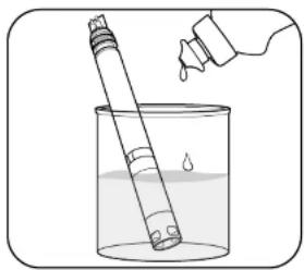
natural_image
Illustration of a test tube being poured into a beaker with liquid, no text or symbols present1 Soak in dishwashing liquid solution
Soak the sensor for 10-15 minutes in a solution of clean tap water and a few drops of dishwashing liquid. Following the soak, rinse the sensor with clean water and inspect. If contaminants remain or response time does not improve, continue to the HCI soak.
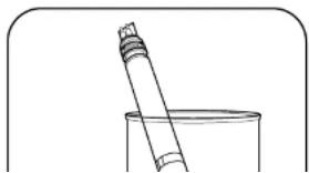
natural_image
Simple line drawing of a pipette and a beaker (no text or symbols)2 Soak in HCl solution
Soak the sensor for 30-60 minutes in one molar (1 M) hydrochloric acid (HCl). This reagent can be purchased from most distributors. Following the HCl soak, rinse the sensor in clean tap water and allow it to soak for an hour in clean water. Stir the water occasionally. Then, rinse the sensor again in tap water and test response time. If response time does not improve or you suspect biological contamination

ISE Maintenance and Storage
EXO Ammonium, Nitrate, and Chloride sensors utilize ion-selective electrodes (I5Es) to monitor these parameters. This section will identify storage as "long-term" or "short-term." Long-term denotes storage during times of long inactivity (over-wintering, end of monitoring season, etc.). Short-term denotes storage during times the sonde will be used at a regular interval (daily, weekly, biweekly, etc.) Replace depleted sensor module as instructed in Section 6.14.
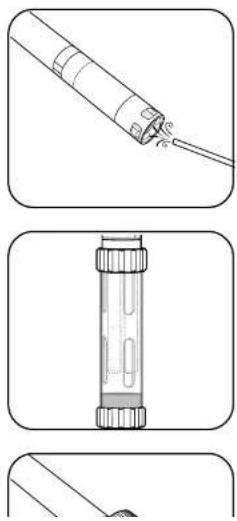
natural_image
Three-step diagram showing a pipe being inserted into a container, with no text or symbols present.1 Sensor maintenance
Ammonium or Nitrate sensor: When deposits, biofouling, or other contamination appear on the membrane, users should gently remove them with a fine jet of deionized water or rinsing in alcohol followed by soaking in the high standard calibration solution. Gently dab dry with a lint-free tissue.
Chloride sensor: When deposits, biofouling, or other contamination appear on the membrane, users should gently remove them by washing with alcohol and/or gently polishing with fine emery paper (400 grit or higher) in a circular motion to remove deposits or discoloration, then thoroughly washing with deionized water to remove any debris.
NOTICE: The ion-selective membranes are very fragile. Do not use coarse materials (e.g. paper towels) to clean the membranes, as these could permanently damage the sensor. The exception is fine emery paper for the chloride sensor, noted above.
2 Short-term storage
When in regular field use, the sensor should remain installed on the sonde in an environment of water-saturated air. Place approximately 0.5 in (1 cm) of tap or environmental water (not deionized or distilled) in the bottom of the calibration cup. Deionized or distilled water can damage ISEs if it contacts the sensor membrane. Insert the sonde into the cup and screw it on tightly to prevent evaporation. (More information in "Short-Term Sonde Storage" Section 6.1.)
6.14 Sensor Module Replacement
EXO pH, pH/ORP, Ammonium, Nitrate, and Chloride sensors feature replaceable sensor modules [part #599795, 599797, 599743-01, 599744-01, 599745-01] due to the electrolyte-depleting characteristics necessary to make such measurements. We recommend that users replace these modules as necessary—typically 12 to 18 months for pH and ORP and three to six months for ISEs, when stored properly. Working life will depend on the conditions of the deployment environment. Perform this procedure in a clean, dry laboratory environment.

natural_image
Diagram of a mechanical assembly with a tool and rotating component (no text or symbols)1 Remove old sticker and plug
Peel off and discard the old sticker that covers the junction of the sensor body and the module. Then, with a small, flat-blade screwdriver, remove the small rubber plug from the gap in the hard plastic ring at the base of the sensor module.

CAUTION: Always exercise extra care when using sharp or potentially harmful instruments.
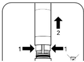
text_image
1 2 12 Remove and discard old sensor module
To remove, perform two motions simultaneously.
- With your fingers, squeeze the sensor module's hard plastic ring so that it compresses the gap left by the rubber plug.
- Steadily pull the sensor module straight back from the sensor body, rocking slightly if necessary.
NOTICE: The set of removing the old cancer module randoms the x rings on the
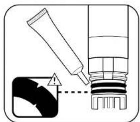
natural_image
Diagram showing a tool applying material to a mechanical component with an arrow indicating direction (no text or symbols present)4 Inspect and service new sensor module's o-rings
Ensure that the two o-rings are not nicked or torn and have no contaminants or particles on them. If the user detects damage, carefully replace them with the extras included in the sensor module kit. Then apply a thin coat of silicone grease to each o-ring, taking care not to get any grease on the gold connector pins. If a user removes a sensor module that is in good working order, replace the o-rings before use.
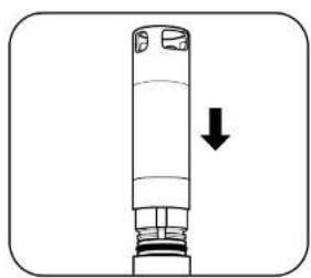
natural_image
Simple line drawing of a cylindrical mechanical component with an arrow indicating downward motion (no text or symbols)5 Insert new sensor module
Align the prongs on the base of the module with the slots in the sensor body. The sensor module is keyed to insert in only one orientation. Once the module is aligned, press it firmly into position until it clicks. Do not twist the module during installation; press it straight in to prevent damage the pins. Wipe away any excess grease from the assembled components.

natural_image
Diagram of a vertical cylindrical device with an arrow indicating rotation or movement (no text or symbols)6 Apply new sticker
Wrap the junction of the sensor module and the body with the new sticker included in the sensor module kit. This sticker helps keep the sensor module junction clean and retains the rubber plug throughout deployment.
On the sticker, use a permanent marker to write the date the replacement module was installed, as a reminder.

EXO Central Wiper
Maintenance and Storage
Follow these instructions to replace the wiper brush assembly or brush guard component on the Central Wiper.
We recommend changing the brush between deployments to avoid sediment carryover, which can compromise calibration and data collection. For long- and short-term storage, the wiper requires minimal precautions. Users can either remove the wiper or leave it installed in the sonde. If left installed on the sonde, follow guidelines for sonde storage. If users remove it from the sonde, the wiper may be stored in dry air in its shipping cap to protect against physical damage.
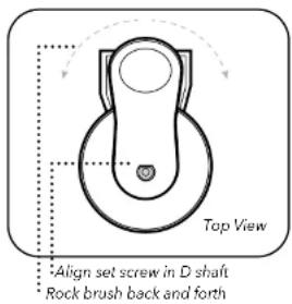
text_image
Top View Align set screw in D shaft Rock brush back and forth1 Replace wiper brush
Loosen set screw with a 0.050 inch Allen wrench. Remove old brush assembly and clean any residue from wiper shaft and wiper end cap.
Install new brush assembly, gently pressing the wiper arm down against the shoulder on the wiper shaft.
Tighten set screw to a torque of 4 inch-pounds. While tightening, gently and slowly rock the brush to ensure a tight fit against the D shaft.
Check snugness of wiper by gently rocking 5 degrees in either direction.
2 Replace brush guard
In Kor Software, go to Run > Dashboard. Click the Wipe Sensors button to ensure proper wiper park position.
Mark the position of the old guard with a marker.
Loosen the #6 screw with a 7/64 inch Allen wrench, remove the old guard and clean any residue from motor housing.
Remove the cover on adhesive strip on the inside of the new brush guard.
Carefully install the new brush guard in same position as old guard—with brush centered in well. Tighten screw until snug, but do not overtighten. (The adhesive helps to hold the guard in place.)
Central Wiper O-Ring Replacement
In order to minimize the chance of water infiltration, YSI recommends annual replacement of the wiper shaft o-rings inside the EXO Central Wiper. This replacement must be performed by a YSI Authorized Service Center. EXO Authorized Service Centers are located in the United States and around the world. Please refer to the YSI website (YSI.com/Repair) for your nearest Authorized Service Center.
SmartQC for the Central Wiper
The central wiper has a QC Score based on the expected voltage of the sensor when seated in the central wiper housing. Users may adjust the seating location by selecting Wiper in the Calibration menu and selecting Jog Left or Jog Right. The seating location should be centered within the housing (brush guard)

natural_image
3D rendered mechanical component with beige and black sections, no visible text or symbolsGuidance on interpretation of the SmartQC Score for this sensor is as follows:

Green: The voltage when the wiper is seated in its housing is within the factory specified limits.

Yellow: The voltage when the wiper is seated in its housing is slightly outside of the factory specified range. If the wiper has a yellow QC Score, perform the following actions:
- Perform a Factory Reset Calibration.
- Calibrate the central wiper so that it seats itself in the correct location.
- Perform a series of wipes on the sonde to ensure that the wiper continues to reseat itself in the correct location after each wipe. Do not manually adjust the central wiper. The wiper calibration will associate a voltage to a location.
Manually moving the wiper will negate the calibration. To perform a sensor wipe:
a. In Kor: On Live Data screen, click the "Start Wiping" button
b. On the Handheld: Click the "Calibration" button, select "Wipe Sensors".
If the central wiper continues to show a yellow QC Score after recalibration, it is still able to be used and will wipe all of the sensors properly. However, the wiper may be nearing its time to be serviced in the factory.

Red: The voltage when the wiper is seated in its housing is outside of the factory specified limits. If the wiper has a red QC

EXO Field Cable Maintenance and Storage
EXO field cables are rugged and provide years of reliable service when properly maintained. As with all field cables, they are most vulnerable at their connectors. Take extra caution to protect the connectors from debris and physical harm.

natural_image
Illustration of two cables with connectors and a cable, no text or symbols present1 Inspect and clean cables
Inspect the cable's connectors for contamination and remove any detected debris with a blast of compressed air. Periodically inspect the cable for nicks and tears to ensure best performance.
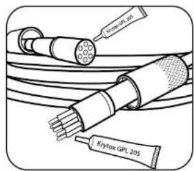
text_image
Cerex GPL 201 Krypton GPL 2052 Lubricate cable connectors
Prior to installation, users should apply a thin coat of silicone grease to both connector ends of the cable and the connector of the sonde. Proper lubrication will help prevent damage to the connectors.
NOTICE: Only a small coating of grease is recommended; connectors should appear shiny. Too much grease is not recommended as it can encourage contamination.

Connectors
Maintenance and Storage
EXO sondes utilize wet mate connectors that greatly reduce problems associated with traditional underwater connectors. However these connectors must be properly maintained to reap the full benefit of this design. Following these instructions will minimize most potential issues.
Never stick any foreign object into a female connector. Use only silicone grease to lubricate the mating surfaces of the connectors.
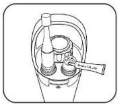
natural_image
Line drawing of a mechanical device with no visible text or symbols1 Female 6-pin connectors
These connectors are located on field cables, the EXO2 accessory connector, and the EXO Handheld. Periodically inspect the connectors for signs of contamination. If you detect debris, remove it with a gentle blast of compressed air. Prior to initial installation, or when dry, apply a light coat of Silicone grease to the flat rubber mating surface on top of the connector. When not in use, always install the connector's plug.
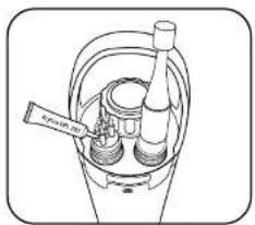
text_image
Spiral pump2 Male 6-pin connectors
These connectors are located on field cables and topside sonde connectors. Periodically inspect the connectors for signs of contamination. If you detect debris, carefully remove it. Prior to initial installation, or when dry, apply a light coat of Silicone grease to the rubber mating surfaces of the connector (including the rubber portions of the pins). When not in use, always install the connector's plug.
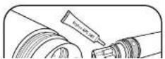
3 Sensor connectors (4-pin)
These connectors are located on sonde bulkheads (sockets) and sensors. Periodically inspect the female portions of these hermaphroditic connectors and

Anti-Fouling Equipment Maintenance
Many components on EXO sondes are made of an anti-fouling copper alloy material that discourages the growth of aquatic organisms. However, longer deployment intervals and highly productive waters can result in biofouling of any equipment, so periodic cleaning may be required.
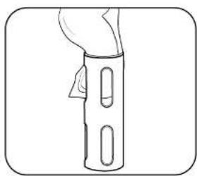
natural_image
Line drawing of a hand holding a cylindrical object with two oval cutouts (no text or symbols)1 Remove minimal biofouling
Remove the anti-fouling sonde guard from the sonde. If the guard is covered in a thin layer of slime or filaments, wipe away the biofouling with a cloth soaked in clean water and a few drops of a dishwashing liquid that contains a degreaser. Rinse the guard with clean water and inspect.

natural_image
Simple line drawing of a cylindrical container with internal oval structures (no text or symbols)2 Soak to remove heavy biofouling
Remove the anti-fouling sonde guard from the sonde. If the guard is covered in a thick layer of filaments or barnacles, soak the guard for 10-15 minutes in a solution of 1:1 white vinegar to clean water. Following the soak, rinse the guard with clean water and inspect.

Flow Cell
Maintenance
There are two versions of the EXO flow cell: EXO1 flow cell [part #599080] and EXO2 / EXO3 flow cell [599201], also compatible with EXO-S sondes. Flow rate of the flow cell is typically between 100 mL and 1 L per minute. Maximum flow rate depends on tubing type, size, and length. Maximum pressure for each is 25 psi.
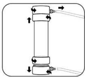
natural_image
Pure mechanical diagram of a cylindrical component with directional arrows indicating force or movement (no text or symbols)1 Disassemble flow cell
To clean the flow cell after use, unscrew and remove the sonde from the flow cell.
Take apart the flow cell by unscrewing the base from the locking ring. Remove the flow cell tube by gently pulling the base and the tube apart. The locking ring will remain on the tube due to the stainless steel retaining ring.
Repeat the same steps to remove the top of the flow cell from the flow cell tube.

natural_image
Simple line drawing of three mechanical components: a curved blade, a cylindrical shaft, and a cylindrical housing (no text or symbols)2 Clean flow cell
Use water and a mild detergent and water to wipe clean the flow cell parts.

Storage Cases Packing Options
EXO sondes are built with the most rugged and durable materials to safeguard against the risks of water monitoring. Out of the water, the EXO Hard-Sided Carrying Case provides a secure manner in which to store your EXO equipment for travel or until the next trip into the field. As seen below, the EXO Hard-Case provides the perfect safe storage solution, though we do offer several case options.
EXO1, EXO2 and EXO3 Storage Solutions
Within the heavy-grade plastic frame, protective foam form fits your EXO sondes. Additionally, the handheld and detached sensors rest safely within foam housing. The central portion of the case allows users to securely stow other miscellaneous items.
There are two separate versions, one which will hold an EXO1 sonde [599020-01], and another that holds an EXO2 or EXO3 sonde [599020-02]. Both versions include wheels for your convenience. It is important to note, however, that with greater durability comes increased size and weight. The dimensions of the EXO Hard-Sided Carrying Case are larger than those of the 6-Series cloth case, and it weighs approximately double.
Due to their smaller size, EXO1, EXO3, and all EXO-S sondes are compatible with both the hard-sided and soft-sided carrying cases, and users should choose the storage solution that is tailored to their individual circumstances. The EXO2, on the other hand, is larger and can only occupy the EXO2/EXO3 hard-sided case. In terms of carrying capacity, both the hard and soft cases are unable to hold multiple EXO2 or EXO3 sondes. The soft-sided case may hold multiple EXO1 or EXO-S sondes.
While the EXO hard-sided cases are designed exclusively for EXO sondes and equipment, the cloth YSI case was originally intended for use with the A-Series

natural_image
Open black hard-shell case containing a handheld tool and mechanical components (no visible text or symbols)EXO Hard-Sided Wheeled Carrying Case
599020-01 (EXO1) and
599020-02 (EXO2 / EXO3)
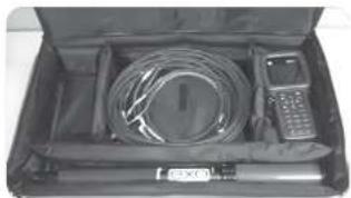
natural_image
Open hard-shell case containing a coiled cable, a handheld device, and a small meter (no visible text or symbols)EXO1 configuration, Soft-Sided Case
Ultimately, while the EXO equipment is built to withstand harsh field environments, we recommend users take care to safely store their systems while not in use. Both the EXO Hard-Sided Carrying Case and the cloth YSI case are viable options, but other non-YSI products may better suit more specialized user needs. (See Appendix below for more information.)

natural_image
Exterior view of a large hard-shell electronic device (no visible text or symbols)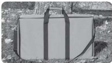
natural_image
Black-and-white photo of a large rectangular object wrapped in black straps, lying on grassy ground (no text or symbols visible)| Item Description Part #’s | |
| EXO1 Wheeled Carrying Case #599020-01 | |
| EXO2 or EXO3 Wheeled Carrying Case #599020-02 |
| Item Description Part # | |
| 6-Series Carrying Case, Soft Sided (EXO1, EXO2 or EXO3 Sonds and equipment) | #696162 |
Appendix: Pelican Cases
Pelican storage cases are another option for EXO users. This third party storage solution is an option for those that prefer to create their own cases for specific purposes. Two Pelican models work the best for storing EXO equipment, the Pelican 1600 and 1700. These cases can be purchased online through a number of portals but do require the user to personally customize the foam interior to fit our sondes and equipment.
Pelican-1600 Pelican-1700


natural_image
Person using a metal detector in water, no visible text or symbols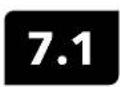
EXO Handheld
General Operation
Keypad and Navigation

text_image
Navigation 12 11 Handheld Deploy Calibration Data 10 Esc 5 9 3 ENTER 8 4 ? 6 7| 1 Handheld: Opens the Setup menu.Use to adjust system settings. | 7 ON/OFF: Push and hold to turn the handheld on or off. |
| 2 Exit/Escape key: Exits to the Dashboard screen. In an alpha/numeric entry screen, push to return to the | 8 Right arrow key: Navigates right in an alpha/numeric entry screen. In the Dashboard screen, |
Startup
Push the ⏻ key to turn on the handheld. If the handheld does not turn on, make sure that the battery pack is correctly installed and charged. Push and hold the ⏻ key for 1.5 seconds to turn off the handheld.
Navigation
The EXO handheld contains menus to change user-defined options, functions, and parameters. Use the arrow keys
(▲ and ▼) to highlight different options within menus and sub-menus, then push the ← key to select the option. Push the ◀ key to return to the previous menu.
Push the ☑ key to return to the Dashboard screen. To enable or disable an option, highlight the option and then push the ☑ key. Enabled functions appear as a circle with a dot ☐ or a box with a check mark ☑ disabled functions appear as an empty circle ☐ or box ☐
Alpha/numeric entry
When displayed, enter information into a numeric or alpha/numeric entry screen. Once the information has been entered, highlight ENTER, then push the ← key.
NOTE: When in an alpha/numeric screen, the ◀ key is for alpha/numeric navigation only. Push the 📄 key to return to the previous menu.
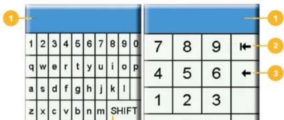
text_image
1 2 3 4 5 6 7 8 9 0 q w e r t y u i o p a s d f g h j k l z x c v b n m SHIFT 7 8 9 ← 4 5 6 ← 1 2 3Dashboard screen description
The Dashboard screen shows the live measurements for units selected in the ▼→ Display → Units menu. If more measurements are selected than can be displayed on the Dashboard screen, a scroll bar will be shown. Use the ▲ and ▼arrow keys to view additional measurements.
The message area shows status messages, error messages, and information about selected functions.
text_image
06/06/16 11:07:50AM Dashboard Log One Sample 21.956 °C 729.0 mmHg 86.2 DO % 0.1 SPC μS cm 7.45 pH 0.79 FNU 0.00 TSS mg L -0.452 PC RFU -0.45 PC ug L -0.058 Chl RFU -0.23 Chl ug L -0.231 fDOM RFU 0.05 fDOM QSU 0.000 DEP mTaking Sampling Measurements
For the highest accuracy, calibrate the instrument before taking measurements (Calibration).
- Create a Site List for logged data (if applicable). (Logging).
- Set the logging method (single or continuous) (Logging).
- Set the Auto Stable parameters (if applicable) (Auto Stable).
- Verify that sensors and/or port plugs are correctly installed in all sonde ports.
- Install the sensor guard
- Insert the sensors into the sample.
NOTE: Make sure to submerge the sensors completely. If using a depth sensor, submerge to where the cable assembly attaches to the sonde.
- Move the bulkhead of the sonde in the sample to release any air bubbles.
- Wait for the sensor/s to stabilize in the sample.
- On the Dashboard screen, press ENTER to begin logging (single or continuous) (Logging).
NOTE: An option to change the Site appears once is pressed on the Dashboard screen to begin logging, as does an option to wipe sensors prior to taking a reading if a wiper is installed.

EXO Handheld
Handheld Menu
Push Handheld key to view and adjust instrument settings. Highlight a sub-
menu then push the ← key to view the sub-menu options.
Pre-defined or user selected options are noted within brackets ([]). See Alpha/numeric entry.
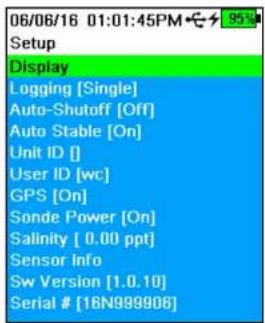
text_image
06/06/16 01:01:45PM Setup Display Logging [Single] Auto-Shutoff [Off] Auto Stable [On] Unit ID [] User ID [wc] GPS [On] Sonde Power [On] Salinity [ 0.00 ppt] Sensor Info Sw Version [1.0.10] Serial # [16N999906]Use the Handheld menu to:
- Setup or change display settings
- Configure logging options (Logging)
- Set an auto-shutoff time for the Handheld
- Change the auto-stable settings
• View and adjust the Unit ID
• View and adjust the User ID
• Tum GPS mode on or off
• Turn power to the sonde on or off
• View sensor specific information (Sensor info)
• View the software version (Software version)
• View the handheld serial number (Serial #)
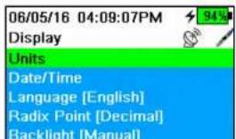
text_image
06/05/16 04:09:07PM 94% Display Units Date/Time Language [English] Radix Point [Decimal] Backlight [Manual]Handheld Display menu
The Handheld Display menu has options to view or change measurement units, date/time, language, radix point, backlight mode, and display brightness.
Use the Display menu to:

text_image
06/06/16 01:26:14PM Date/Time Date Format [MM/DD/YY] Date [06/06/18] Time Format [12-hour] Time [01:26:09PM]Date/Time
→ Display → Date/Time
For accurate logging and calibration data, set the date and time for the EXO handheld.
Date/Time options:
- Set YY/MM/DD, MM/DD/YY, DD/MM/YY or YY/DD/MM date format
- Set the current date
- Select 12 or 24 hour time format
- Set the current time
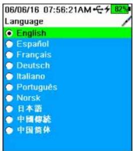
text_image
06/06/16 07:56:21AM Language English Español Français Deutsch Italiano Português Norsk 日本語 中国傳統 中国简体Display Language
→ Display → Language
The EXO handheld is shipped with English as the default language. When the language setting is changed, the handheld will take 10 to 20 seconds to update the language settings.
Included languages
- French
• German - Italian
- Japanese
- Norwegian
- Portuguese
- Simplified Chinese
- Spanish
• Traditional Chinese

Display Backlight
→ Display → Backlight
In Automatic mode, the keypad backlight will turn off 60 seconds after the last key is pushed. Once any key is pushed, the keypad backlight will turn back on and remain on for another 60 seconds of inactivity.
When Manual mode is selected, the handheld backlight key is used to turn the keypad backlight on or off.
NOTE: In low light conditions, set the backlight to remain on using Manual mode.
Display Large Graphs
→ Display
For larger graphical displays of data, select the Large Graphs check box and then push the ← key.

text_image
06/05/16 04:09:07PM Display Units Date/Time Language [English] Radix Point [Decimal] Backlight [Manual] Large Graphs Brightness:Display Brightness
→ Display → Brightness
The screen display brightness can be adjusted to accommodate lighting conditions and to conserve battery power.
Select Brightness and then use the ◀ and ▶arrow keys to adjust the screen brightness.
NOTE: In bright conditions, set the screen brightness to 75%

text_image
06/05/16 04:40:54PM Logging ✓ Use Site List Site [Yellow Springs] Site Order [Date] □ Continuous Mode Log Interval [00:00:05.00]Logging
→ Logging
The Logging menu has options for user-defined sites to be included with the logged data. When the Site List is enabled, select which site to save data to when logging.
Highlight Use Site List check box and push the 📋 to enable the Site List feature.
Select Site to access the Site List menu, where new sites can be added and previously saved sites can be edited or deleted.
Select Site Order to change how the site names are arranged in the Site List, either by name, date, or distance.
Continuous Mode (interval logging): When Continuous mode is enabled, the handheld will log data at a specified interval until stopped. Edit the logging time interval by selecting Log Interval. The Dashboard screen will display Start Logging... when in Continuous mode.
One Sample Logging: When Continuous mode is not selected, the Dashboard screen will display Log One Sample. A single sample will be logged each time the icon is pushed when in the Dashboard screen.
NOTE: An option to change the Site appears once the pressed on the Dashboard screen to begin logging, as does an option to wipe sensors before taking a measurement if a wiper is installed.
Auto-Shutoff
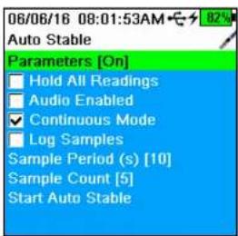
text_image
06/06/16 08:01:53AM Auto Stable Parameters [On] Hold All Readings Audio Enabled Continuous Mode Log Samples Sample Period (s) [10] Sample Count [5] Start Auto StableAuto Stable
→ Auto Stable
Auto Stable indicates when a measurement is stable and can be monitored for each parameter.
Sensors with Auto Stable enabled will have A or S flash beside the measurement on the Dashboard screen.
A will flash green when the measurement is stable
A s will flash red when a measurement is unstable
Hold All Readings: After all sensors have reached their stability criteria, the measurements will be held or 'locked' on the display. If disabled, the sensor measurements will continue to change in real time.
Audio Enabled: An audio alert will sound when stability is reached.
Continuous Mode: The EXO handheld will continuously check sensor values against the stability criteria even after the sample period and sample count have been met.
Log Samples: Logs the sample/s defined by the Sample Period to memory.
Sample Period: Time interval between the sensor measurements (sample) that are used to determine stability. Set the interval in seconds (1 to 900).
Sample Count: Number of consecutive samples required for stability (1 to 10).
Auto Stable Parameters
06/05/16 04:20:20PM
Auto Stable Temperature
→ Auto Stable → Parameters
Enter the stability value, then select Use Percent or Use Meas. Units.
This threshold is used to compare the last reading with the previous. The smaller

text_image
06/05/16 04:09:07PM Display Units Date/Time Language [English] Radix Point [Decimal] Backlight [Manual] Large Graphs Brightness:Unit ID
The Unit ID is specific to the instrument and is used to identify calibration files, Site Lists, Configuration Files, and Data files transferred from the handheld to a PC.
User ID

The User ID is a record of who used the Handheld to record data or calibrate sensors. This metadata is stored with each calibration record.
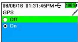
GPS

Use the GPS menu to turn the Global Positioning System On or Off. The symbol is displayed when a GPS signal is received.
When enabled, the GPS coordinates will be saved with calibration records and logged data.
NOTE: GPS data will be most accurate when there is a clear line of sight to satellites. GPS will not typically receive a signal while inside a building.
NOTE: Disabling GPS will conserve handheld battery power.
| 06/06/16 08:16:37AM | |
| Sensor Diagnostics | |
| Sensor: | Handheld |
| Mfg S/N: | 16N999906 |
| S/W Ver: | 1.0.10 |
| PCB S/N: | 15110010 |
| Supply V: | 11.73 |
| ETime s: | 2982.970 |
| Baro (mmHg): | 729.5 |
| GPS Date: | 00/00/00 |
| GPS Time: | 00:00:00 |
| GPS Lat: | 0.00000* |
| GPS Long: | 0.00000* |
| GPS Alt (m): | 0.0 |
Sensor info

→ Sensor info
The Sensor info menu displays information about the handheld and each connected sensor. Use this menu to view sensor settings, measurement data, Smart QC Scores, and software/hardware information. Use the ▲ and ▼row keys to scroll through information about each component.
NOTE: This is a helpful menu to review when troubleshooting with a technical support representative.
Software (Sw) Version

→ Sw Version
This menu displays the EXO handheld software version currently installed on the instrument.
NOTE: The latest instrument software version can be downloaded using the Kor Software program available from YSI.com.
EXO Handheld
Deploy Menu
Use the Deploy ⚙️ key to configure sonde deployment settings, view the current status of a deployment, or to start or stop a deployment.
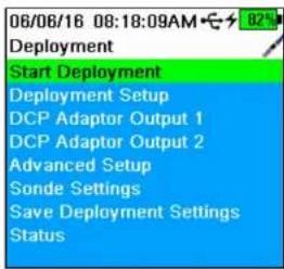
text_image
06/06/16 08:18:09AM Deployment Start Deployment Deployment Setup DCP Adaptor Output 1 DCP Adaptor Output 2 Advanced Setup Sonde Settings Save Deployment Settings StatusUse the Deployment menu to
- Start or stop a sonde deployment
- Setup deployment options
- Setup DCP adapter outputs (for external data loggers)
- Access advanced setup options
■ View or change sonde specific settings - Save updated settings to sonde without starting deployment
• View current sonde configuration
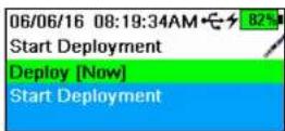
Start Deployment
→ Start Deployment
Select when the sonde begins logging measurements autonomously in the Start Deployment menu.
Deploy: Setup when the sonde will begin collecting data. Select Now to immediately begin autonomously data collection or select Next Interval to begin collecting data on the next logging interval. Select Custom Time to have the sonde begin data collection at a specified time.
Start Deployment: Select to begin collecting data with the current deployment
-
-
-
-
-
-
-
-
-
-
-
-
-
-
-
-
-
-
-
-
-
-
-
-
-
-
-
-
-
-
-
-
-
-
-
-
-
-
-
-
-
-
-
-
-
-
-
-
-
-
-
-
-
-
-
-
-
-
-
-
-
-
-
-
-
-
-
-
-
-
-
-
-
-
-
-
-
-
-
-
-
-
-
-
-
-
-
-
-
-
-
-
-
-
-
-
-
- 99.
-
-
-
-
-
-
-
-
-
-
-
-
-
-
-
-
-
-
-
-
-
-
-
-
-
-
-
-
-
-
-
-
-
-
-
-
-
-
-
-
-
-
-
-
-
-
-
-
-
-
-
-
-
-
-
-
-
-
-
-
-
-
-
-
-
-
-
-
-
-
-
-
-
-
-
-
-
-
-
-
-
-
-
-
-
-
-
-
-
-
-
-
-
-
-
-
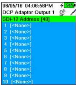
text_image
Terminal interface showing SDI-12 address list with 10 numbered
text_image
06/05/16 04:04:09PM Advanced Setup Mode [Normal] Burst Duration [00:00:00.00] Avg. Duration [00:00:00.00] Wipe Interval [1] Adaptive Logging [Off]
DCP Adaptor Outputs
→ DCP Adapter Output (1 or 2)
The Data Collection Platform (DCP) Adapter Output menu is for users who have a DCP Adapter and are connecting a sonde to an external data logger. Use the DCP Adapter menu to setup how the sonde interacts with the data logger.
Set the address to a number (0-9) or a single letter (A-Z) so that the data logger can identify from which source the data should be pulled.
Set which parameters the data logger will record and the order in which that data is collected. Refer to the main user manual to learn more about DCP adapter functions:
NOTE: The sonde and the data logger must be set with the same parameters, in the same order.
Advanced Setup
→ Advanced Setup
The Advanced Setup menu offers advanced users additional deployment settings for sonde data collection.
Advanced Setup Mode
→ Advanced Setup → Mode
This advanced menu allows users to customize how the instrument logs data.
Sample & Hold: This mode is helpful when connecting a sonde to a data logger. In this mode the sonde saves collected data to an internal SD card, which can
06/05/16 04:04:16PM
Adaptive Logging
Interval [00:00:01.00]
Duration [00:00:00.00]
Parameter 1 [pH]
Mode 1 [Off]
Threshold 1 [0.00]
Parameter 2 [
Mode 2 [Off]
Threshold 2 [0.00]

Advanced Setup Wipe Interval

→ Advanced Setup → Wipe Interval
Set the interval (in measurements) between when sensors are wiped.
Advanced Setup Adaptive Logging

→ Advanced Setup → Adaptive Logging
The Adaptive Logging option is used to temporarily change the defined sonde logging interval if one or two specified parameters exceed a user-defined threshold. This feature is helpful for capturing additional data during events (floods, illicit discharges, algal blooms, etc.).
When data exceeds set thresholds during a logging interval (defined in Deployment Setup), the logging interval will automatically increase to a user-specified frequency. Once data fall back within threshold limits, the logging interval will return to its defined settings.
Assign Adaptive Logging for up to two parameters by selecting Parameter 1 and/or Parameter 2. Select Mode to choose if Adaptive Logging will activate if a parameter rises above or dips below a set threshold.
Set the new logging interval when these parameters exceed the set threshold. Also, set the duration the sonde will continue collecting data at the modified logging interval.
NOTE: When adaptive logging is enabled, all memory and battery life estimates are no longer accurate.
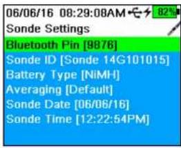
text_image
06/06/16 08:29:08AM Sonde Settings Bluetooth Pin [9876] Sonde ID [Sonde 14G101015] Battery Type [NiMH] Averaging [Default] Sonde Date [06/06/16] Sonde Time [12:22:54PM]Sonde Settings

→ Sonde Settings
View or change sonde-specific settings in the Sonde Settings menu, including the sonde date and time, bluetooth pin number, battery type, and averaging mode.
Use the Sonde Settings menu to
- Assign a bluetooth pin number
• View or change the Sonde ID - Select the sonde battery chemistry
- Access Sonde Settings
- Set the sonde date and time
- Save Deployment Settings
• View the Deployment Status
NOTE: After the sonde settings have been entered, highlight Save
Deployment Settings and push the ← key.

text_image
06/06/16 08:30:04AM Averaging Mode ● Default ● Accelerated ● RapidSonde Settings Averaging

→ Sonde Settings → Averaging
Default mode provides optimum data filtering for all sensors and the highest accuracy during unattended monitoring at a fixed location. This mode has up to 40 seconds of filtering on sensors.
NOTE: All sensors ship in default mode.
In Accelerated mode, sensors record data with a smaller rolling average window (5-10 seconds), so changes in sensor response are more quickly observed. Accelerated mode is recommended when the sensors are moving through the
EXO Handheld
Calibration Menu
Push the 🔒 key to access the Calibration menu. Highlight a sub-menu then push the ⏻ key to view sub-menu options.
NOTE: Only sensors installed in the sonde will appear on the Calibration menu scree
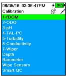
text_image
06/05/16 03:36:47PM 94% Calibration 1-fDOM 2-ODO 3-pH 4-TAL-PC 5-Turbidity 6-Conductivity 7-Wiper Depth Barometer Wipe Sensors Smart QCUse the Calibration menu to:
- Calibrate sensors
- Setup sensors for calibration
- Restore default calibrations
- Set a Calibration Reminder
- Wipe sensors
• View Smart QC scores
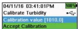
Calibration Screen Layout
The calibration screen has the same basic layout for each parameter.
Calibration value: The value to which the sensor will be calibrated.
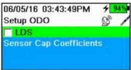
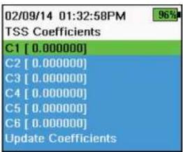
text_image
02/09/14 01:32:58PM 96% TSS Coefficients C1 [ 0.000000] C2 [ 0.000000] C3 [ 0.000000] C4 [ 0.000000] C5 [ 0.000000] C6 [ 0.000000] Update CoefficientsSensor-Specific Setup Menus
Setup ODO
→ODO → Setup
LDS: Last Digit Suppression (LDS) rounds the Dissolved Oxygen (DO) value to the nearest tenth, e.g. 8.27 mg/L becomes 8.3 mg/L.
Sensor Cap Coefficients: The sensor cap coefficients must be updated after sensor cap replacement to maintain Optical Dissolved Oxygen (ODO) accuracy. Update the sensor cap coefficients using the Handheld and the coefficient sheet provided with the new sensor cap.
Update sensor cap coefficients by entering the K1-K7 and KC values from the sensor cap calibration sheet. When the values have been entered, highlight
Update Coefficients and push the key to save the coefficients. Alternatively, coefficients can be entered into the Kor Software application and loaded into the instrument.
Setup Turbidity TSS Coefficients
→ Turbidity → Setup
TSS Coefficients are calculated in Kor by entering turbidity and Total Suspended Solids (TSS) correlation data.
Measure turbidity and take a grabsample for laboratory analysis of TSS to obtain a value pair for the correlation. At least two and up to six value pairs can be entered into Kor.
Update TSS coefficients by entering the C1-C6 values in the TSS Coefficients sub-menu. When the values have been entered, highlight Update Coefficients
and push the ← key to save the coefficients. Alternatively, coefficients can be entered into the Kor Software application and loaded into the instrument.
NOTE: For highest accuracy, obtain 6 values pairs and calculate new coefficients for each unique sampling site.

Setup Conductivity
→ Conductivity → Setup
Temp Ref (Temperature Reference): The reference temperature is used to calculate temperature-compensated specific conductance readings. The default Temperature Reference value is 25 °C (77 °F). Set the Temperature Reference to a different value by selecting Temp Ref and entering a value between 15.00 °C (59 °F) and 25.00 °C (77 °F).
%/°C (Percent per degree Celsius): Percent per degree Celsius is the temperature compensating coefficient used for Specific Conductance readings. The default is 1.91% based on KCl standards. To change the coefficient, enter new value between 0 and 4%.
TDS Constant: The total dissolved solids (TDS) constant is a multiplier used to calculate an estimated Total Dissolved Solids (TDS) value from conductivity. The multiplier is used to convert specific conductance in mS/cm to TDS in g/L. The default value is 0.65. Enter a new value between 0 and 0.99.
This multiplier is highly dependent on the nature of the ionic species present in the water sample. To be assured of moderate accuracy for the conversion, you must determine a multiplier for the water at your sampling site. Use the following procedure to determine the multiplier for a specific sample:
- Determine the specific conductance of a water sample from the site.
- Filter a portion of water from the site.
- Carefully measure a volume of the filtered water. Completely evaporate to yield a dry solid.
- Accurately weight the remaining solid.
- Divide the weight of the solid (in grams) by the volume of water used (in liters) to yield the TDS value in g/L for the site.
Conductivity
A conductivity/temperature sensor must be installed for accurate temperature compensation and measurements of all parameters. Temperature calibration is not available or required for accurate temperature measurements.
The conductivity/temperature sensor can measure and calculate conductivity, specific conductance (temperature compensated conductivity), salinity, non-linear function (nLF) conductivity, TDS, resistivity, and density. Calibration is only available for specific conductance, conductivity, and salinity. Calibrating one of these options automatically calibrates the other conductivity/temperature parameters listed above. For both ease of use and accuracy, YSI recommends calibrating specific conductance.
Conductivity calibration

text_image
05/19/16 01:50:04PM 70% Calibrate Sp. Cond. Calibration value [ 1000] Accept Calibration Press ESC to Abort Last Calibrated 04/29/16 02:31:22PM Actual Readings 22.9 °C 1014 SPC-uS/cm Post Cal Value 1000 SPC-uS/cm SPC-uS/cm 1034.6 1007.3 980.0 Ready for point- If necessary, clean the conductivity cell with the supplied soft brush. See full EXO User Manual for more details on sensor maintenance.
- Perform the related Calibration setup on the previous page.
- Place the correct amount of conductivity standard into a clean and dry or pre-rinsed calibration cup.
NOTE: Select the appropriate calibration standard for the conductivity of the sampling environment. Standards greater than 1 mS/cm (1000 S/cm) are recommended for the greatest stability. For fresh water applications, calibrate to 1,000 or 10,000 S. For salt water applications, calibrate to 50,000 S.
- Carefully immerse the sensors into the solution. Make sure the solution is above the vent holes on the side of the standard conductivity sensor, or above the sensor face of the Wiped conductivity sensor.
- Gently rotate and/or move the sensor up and down to remove any bubbles from the conductivity cell. Allow at least one minute for temperature equilibration before proceeding.
- Push the 🔒 key, select Conductivity, then select Specific Conductance.
NOTE: Calibrating any conductivity calibration option will automatically calibrate the other options. Specific conductance is
NOTE: If the data is not stabilized after 40 seconds, gently rotate the sensor or remove/reinstall the calibration cup to make sure that no air bubbles are in the conductivity cell.
NOTE: If the actual measurement data is about 1/2 if the expected calibration value, the conductivity sensor is not completely submerged. Add more calibration standard to the calibration cup.
NOTE: If you get calibration error messages, check for proper sensor immersion, verify the calibration solutions is fresh, the correct value has been entered into the EXO Handheld, and/or try cleaning the sensor.
- Rinse the Sonde bulkhead and sensors in clean water then dry.
Barometer
The barometer is factory calibrated and should rarely need to be recalibrated. The barometer is used for DO calibration, and %Local measurements. Verify that the barometer is accurately reading "true" barometric pressure and recalibrate as necessary.
Laboratory barometer readings are usually "true" (uncorrected) values of air pressure and can be used "as is" for barometer calibration. Weather service readings are usually not "true", i.e. they are corrected to sea level and cannot be used until they are "uncorrected". Use this approximate formula:
True BP in mmHg=[Corrected BP in mmHg] - [2.5* (Local altitude in ft. above sea level/100)]
Example:
Corrected BP = 759 mmHg
Local altitude above sea level = 978 ft
True BP = 759 mmHg - [2.5*(978ft/100)] = 734.55 mmHg

Barometer calibration
-
Push the 🔒 key, then select Barometer.
-
Select Calibration value then enter the correct "true" barometric pressure.
Dissolved oxygen
ODO % Saturation calibration requires the current "true" barometric pressure. Make sure that the barometer is reading accurately and recalibrate the barometer as necessary.

text_image
05/19/16 01:34:55PM G 77% Calibrate ODO Calibration value [97.3] Accept Calibration Barometer [739.5] Press ESC to Abort Last Calibrated 05/19/16 11:08:37AM Actual Readings 23.1 Ref °C 98.1 DO % Post Cal Value 97.3 DO % DO % 97.7 96.2 0 150 Ready for pointDO% Sat and DO% Local - water saturated air calibration
NOTE: This method calibrates the instrument's DO % Set measurement or DO % Local measurement if DO % CB (Calibrated Barometer) or % RTB (Real-Time Barometer) is enabled in the sensor setup menu. See Section 5.11 Dissolved Oxygen Sensor Overview for more information on these units. Use the % RTB unit to calculate local DO from live readings from the handheld's internal barometer.
NOTE: Calibrating in DO % Sat, % CB, or % RTB automatically calibrates the mg/L and ppm measurement. For both ease of use and accuracy, we recommend that you calibrate DO % Sat, % CB, or % RTB and not mg/L.
- Place a small amount of clean water (1/8 inch) into the calibration cup.
- Make sure there are no water droplets on the ODO sensor cap or temperature sensor.
- Attach the sensor guard to the bulkhead and carefully place the guard/sensor into the calibration cup. Partially tighten the calibration cup to the bulkhead.
NOTE: Do not fully tighten the calibration cup to the bulkhead. Atmospheric venting is required for accurate calibration.
NOTE: Make sure the ODO and temperature sensors are not immersed in water.
- Turn the instrument on and wait approximately 5 to 15 minutes for the air in the storage container to be completely saturated with water.
- Push the ⚙ key, then select ODO. Select DO%. This will calibrate the

text_image
05/19/16 02:11:33PM 79% Calibrate ODO Calibration value [ 7.80] Accept Calibration Salinity [ 0.00] Press ESC to Abort Last Calibrated 05/19/16 11:08:37AM Actual Readings 23.1 Ref °C 8.59 DO mg/L Post Cal Value 7.80 DO mg/L 8.8 8.2 7.6 DO mg/L Ready for point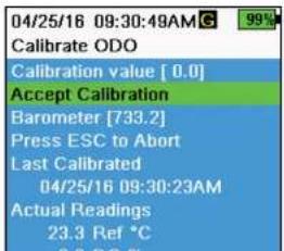
text_image
04/25/16 09:30:48AM Calibrate ODO Calibration value [ 0.0 ] Accept Calibration Barometer [733.2] Press ESC to Abort Last Calibrated 04/25/16 09:30:23AM Actual Readings 23.3 Ref °CDO mg/L calibration
- Place the ODO and conductivity/temperature sensor into a water sample that has been titrated by the Winkler method to determine the dissolved oxygen concentration in mg/L.
- Push the ⚪ key, then select ODO. Select DO mg/L.
- Select Calibration value.
- Enter the dissolved oxygen concentration of the sample in mg/L.
- Observe the actual measurement readings for stability (white line on graph shows no significant change for 40 seconds), then select Accept Calibration. "Calibration successful!" will be displayed in the message area.
- Rinse the bulkhead and sensors in clean water then dry.
DO zero point calibration
- Place the ODO and Conductivity/Temperature sensors in a solution of zero DO.
NOTE: A zero DO solution can be made by dissolving approximately 8-10 grams of sodium sulfite into 500~mL of tap water. Mix the solution thoroughly. It may take the solution 60 minutes to be oxygen-free.
-
Push the ⚫ key, then select ODO. Select Zero.
-
Observe the actual measurement readings for stability (white line on graph shows no significant change for 40 seconds), then select Accent
pH/ORP
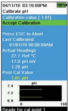
bar
| Time (min) | pH | |---|---| | 0 | 7.4 | | 30 | 7.2 | | 60 | 6.9 | | 90 | 7.2 | | 120 | 7.2 | | 150 | 7.01 |pH calibration 1-point
NOTE: If performing a 1-point calibration, use buffer 7 (6.86) as your calibration point for highest accuracy.
NOTE: Observe the pH mV readings during calibration to understand the condition and response of the pH sensor. In buffer 7, pH mVs should be between -50 and +50. In buffer 4, the mVs should be a +165 to 185 away from the pH 7 mV value. In buffer 10, the mVs should be a -165 to -185 away from the pH 7 mV value. Ideal slope is -59 mV per pH unit.
- Perform the Calibration setup.
- Fill the calibration cup to the appropriate level with pH 7 buffer solution (or 6.86 if using NIST buffers).
- Carefully immerse the probe end of the sensors into the buffer solution.
- Push the ⚙ key, then select pH or pH/ORP.
NOTE: If using a pH/ORP sensor, select pH/ORP, then pH. - Allow at least one minute for temperature stabilization. The Calibration value will automatically be adjusted based on the selected buffer set and temperature. Alternatively, the Calibration value can be manually entered.
- Observe the actual measurement readings for stability (white line on graph shows no significant change for 40 seconds), then select Accept Calibration. "Ready for cal point 2" will be displayed in the message area.
- After calibrating to the first point, select Finish Calibration for a 1-point calibration or continue on to the 2-3 point calibration procedure.
pH calibration 2- or 3-point

text_image
04/11/16 03:20:02PM Calibrate pH Calibration value [ 4.00 ] Accept Calibration Finish Calibration Press ESC to Abort Last Calibrated 01/01/70 00:00:00AM Actual Readings 22.6 Ref °C 155.9 pH mV 4.34 pH Post Cal Value 4.00 pH pH 4.5 4.2 3.9 262 412 Ready for cal point 2NOTE: if performing a 2- or 3-point calibration, one point should be in buffer 7; however, the calibration points can be in any order.
- Perform steps 1-7 of the pH calibration 1-point procedure (1-Point pH Calibration).
- Rinse the sensor 2-3 times with a small amount of pH 4 or pH 10 buffer solution.
- Rinse, then fill the calibration cup to the appropriate level with the buffer solution that is the same value (pH 4 or pH 10) used to rinse the sensor.
-
Carefully immerse the sensors into the solution.
-
Allow at least one minute for temperature stabilization. The Calibration value will automatically be adjusted based on the selected buffer set and temperature. Alternatively, the Calibration value can be manually entered.
-
Observe the actual measurement readings for stability (white line on graph shows no significant change for 40 seconds), then select Accept Calibration. "Ready for cal point 3" will be displayed in the message area.
-
After calibrating to the second point, select Finish Calibration for a 2-point calibration or continue with an additional buffer to complete a 3-point calibration. The procedure will automatically finish after calibrating using a third buffer.

text_image
05/19/16 02:29:18PM 37 calibration Calibrate ORP Calibration value [234.5] Accept Calibration Press ESC to Abort Last Calibrated- Obtain/prepare a standard with a known oxidation reduction potential (ORP) value.
NOTE: YSI recommends Zobell solution.
Depth
NOTE: This calibration option is available only if your sondo is equipped with a depth sensor. For the calibration, make sure that the depth sensor is clean and in air, not immersed in any solution. For highest accuracy, keep the bulkhead still and in one position while calibrating.
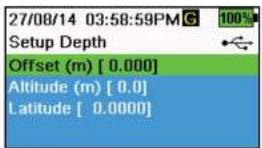
text_image
27/08/14 03:58:59PMG 100% Setup Depth Offset (m) [ 0.000] Altitude (m) [ 0.0] Latitude [ 0.0000]Setup Depth
→ Depth → Setup
Offset: Depth offset can be used if referencing water elevation against a known datum. If a depth offset is entered (in meters), the output value will shift by the value of the offset.
Altitude/Latitude: To compensate for atmospheric pressure based on elevation and gravitational pull, enter the local altitude in meters relative to sea level and latitude in degrees where the EXO handheld is sampling.
Altitude effect: Varying altitudes cause approximately 90 mm change from sea level to 8000 m. A 100 m change causes 1.08 mm of change to the readings.
Latitude effect: Varying latitudes cause a 200 mm change in depth from equator to pole.
Depth calibration
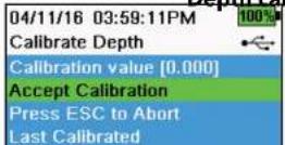
- If applicable, enter the depth offset, altitude, and latitude.
NOTE: Depth offset allows you to set the depth measurement to something other than zero. If the depth offset is used, the depth measurement will be adjusted by the offset after calibration. Enter

text_image
04/11/16 03:41:01PM Calibrate Turbidity Calibration value [1010.0] Accept Calibration Finish Calibration Press ESC to Abort Last Calibrated 04/11/16 03:35:43PM Actual Readings 1005.3 FNU Post Cal Value 1010.0 FNU FNU 1030.2 1005.9 981.5 118 268 Ready for cal point 3Turbidity calibration 1-, 2- or 3-point
NOTE: The sensor guard must be installed for the turbidity sensor calibration.
NOTE: When performing a turbidity calibration, the first point must be zero. Select Calibration Value and enter 0.00.
- Perform the Calibration setup. Rinse the sensor 2-3 times with a small amount of 0 FNU (NTU) standard.
- Fill the calibration cup to the appropriate level with 0 FNU (NTU) standard (clear deionized or distilled water is suitable). Immorse the sensors into the water.
NOTE: With the calibration cup empty (i.e. no sensor guard or sensors), filling the calibration cup to line 1 will provide a sufficient amount of solution for calibration. - Push the 🔊 key, then select Turbidity.
- Select Calibration Value and enter 0.00.
- Observe the data points readings for stability with the 0 FNU (NTU) standard (white line on graph shows no significant change for 40 seconds), then select Accept Calibration. "Ready for cal point 2" will be displayed in the message area.
- Select Finish Calibration to complete a 1-point calibration or continue for the 2- or 3-point calibration.
- Rinse the sensors, calibration cup, and sensor guard 2-3 times with a small amount of standard #2. Discard the standard after each rinse.
- Fill the calibration cup to the appropriate level with standard #2. Immerse the sensors in the second calibration standard.
- Select Calibration Value and enter the value of the second calibration standard.
ISEs: Ammonium, Nitrate, & Chloride
Before performing the calibration, review Calibration setup.
The ISEs can be calibrated to one, two or three points. A 2-point calibration without chilling a third calibration solution is extremely accurate and is the preferred method. However, if there is a large temperature variation during sampling, a chilled third calibration point is recommended.
Higher calibration accuracy can be obtained if the standards used have a least one order of magnitude difference between them. For example, 1 mg/L and 10 mg/L or 10 mg/L and 100 mg/L.
mV information for the ISE calibration
Ammonium mV values
- NH_4 1 mg/L = 0 mV +/- 20 mV (new sensor only)
- NH_3100mg / L = 90 to 130mV > 1mg / L mV value
- The mV span between 1 mg/L and 100 mg/L values should be ≈ 90 to 130 mV.
The slope should be 45 to 65 mV per decade.
Nitrate mV values
- NO _2 1 mg/L = 200 mV +/- 20 mV (new sensor only)
- NO_3 , 100mg / L = 90 to 130mV < 1mg / L mV value
- The mV span between 1 mg/L and 100 mg/L values should be ≈ 90 to 130 mV.
The slope should be -45 to -65 mV per decade.
Chloride mV values
- Cl 10 mg/L = 225 mV +/- 20 mV (new sensor only)
- Cl 1,000 mg/L = 80 to 130 mV < 10 mg/L mV value
- The mV span between 10 mg/L and 1000 mg/L values should be ≈ 80 to 130 mV.
The slope should be -40 to -65 mV per decade.
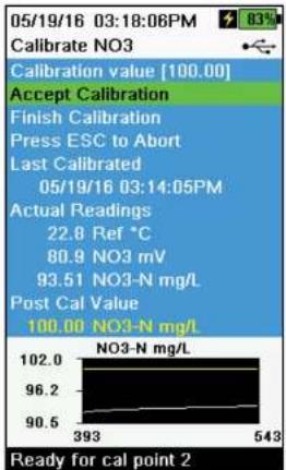
text_image
05/19/16 03:18:06PM Calibrate NO3 Calibration value [100.00] Accept Calibration Finish Calibration Press ESC to Abort Last Calibrated 05/19/16 03:14:05PM Actual Readings 22.8 Ref °C 80.9 NO3 mV 93.51 NO3-N mg/L Post Cal Value 100.00 NO3-N mg/L NO3-N mg/L 102.0 96.2 90.5 393 543 Ready for cal point 2ISE calibration 3-point
- Perform the Calibration setup. Rinse the sensor 2-3 times with a small amount of standard #1.
NOTE: It is best to calibrate in order of increasing concentration (e.g. if using 1 mg/L and 100 mg/L standards, calibrate with 1 mg/L first). - Push the key, then select the applicable ISE.
- Carefully immerse the sensors into a solution of standard #1.
- Allow the temperature of the standard to stabilize, then select Calibration value. Enter the calibration value that corresponds to standard #1.
- Observe the actual measurement readings for stability (white line on graph shows no significant change for 40 seconds), then select Accept Calibration. "Ready for cal point 2^* will be displayed in the message area."
- Select Finish Calibration to complete a 1-point calibration. Otherwise, continue the calibration procedure to complete at least a 2-point calibration.
NOTE: A 2-point calibration is extremely accurate and is the preferred method. - Rinse the sensor 2-3 times with a small amount of standard #2. Discard the standard after rinsing.
- Carefully immerse the sensors into a fresh solution of standard #2.
- Allow the temperature of the solution to stabilize then select Calibration value. Enter the calibration value that corresponds to standard #2.
- Observe the actual measurement readings for stability (white line on graph shows no significant change for 40 seconds), then select Accept Calibration. "Ready for cal point 3" will be displayed in the message area.
- Select Finish Calibration to complete a 2-point calibration. Otherwise, continue the calibration procedure to complete a 3-point calibration.
NOTE: To calibrate with a chilled third standard, see Chilled third calibration
Chilled third calibration point
The 3-point calibration method assures maximum accuracy when the temperature of the media to be monitored cannot be anticipated. If you must perform a chilled 3-point calibration, the following procedure requires one portion of the high concentration calibration solution and two portions of the low concentration calibration solution.
The high concentration solution and one of the low concentration solutions should be at ambient temperature. The other low concentration solution should be chilled to less than 10 °C ( 50 °F ) to prior calibration point.
See ISE calibration 3-point on previous page.
- When "Ready for cal point 3" is displayed in the message area during ISE calibration, place the proper amount of chilled 1 mg/L standard (10 mg/L for the chloride) into a clean, dry or pre-rinsed calibration cup.
- Carefully immerse the sensor into the solution. Allow for temperature equilibration. If necessary, select Calibration value to manually enter the standard #3 value.
- Once the readings are stable, select Accept Calibration. "Calibration successful!" will be displayed in the message area.
fDOM & Total Algae (TAL) Sensors
For more information on fDOM and Total Algae (TAL) Calibration, please review the full EXO User Manual.
- Push the 🔒 key, then select fDOM or TAL
Wipe Sensors

→ Wipe Sensors
Highlight Wipe Sensors on the Calibration menu and push the ENTER to wipe the sonde sensors.
NOTE: An EXO Central Wiper must be installed to activate this command.
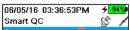
Smart QC

→Smart QC
7.5
EXO Handheld
Data Menu
Push the ☐ key to access the Data menu. Highlight a sub-menu then push the ⬆ key to view sub-menu options.
Use the Data menu to view data recorded via the Handheld dashboard.
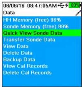
text_image
06/06/16 08:47:05AM 83% Data HH Memory (free) 96% Sonde Memory (free) 99% Quick View Sonde Data Transfer Sonde Data View Data Delete Data Backup Data View Cal Records Delete Cal RecordsUse the Data menu to
• View available handheld memory
• View available sonde memory
• View handheld and sonde data
- Transfer data files from sonde to Handheld
- Delete data
- Backup data to USB
• View calibration records
- Delete calibration records
Quick View Sonde Data

→ Quick View Sonde Data
View logged data that has been selected in the data filter settings. Use the ▲
and arrow keys to scroll through rows of individual data sets. Use the he
and ▶arrow keys to view additional data for each data set.

Transfer Data Filter

Transfer Sondo Data
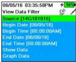
text_image
06/05/16 03:35:58PM View Data Filter Source [14G101015] Begin Date [06/05/16] Begin Time [00:00:00AM] End Date [06/06/16] End Time [00:00:00AM] Show Data Graph DataView Data Filter

→ View Data
Use the View Data Filter menu to view and graph logged data over a specified time period. Enter the desired filter criteria, then select Show Data or Graph Data to view the tabular or graphical data. If necessary, use the ▲ and ▼row keys to scroll through the data.
Source: View data recorded on the Handheld or sonde.
Site: View data from one site or all sites.
Begin/End: View data within specified date and time ranges.
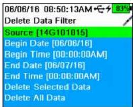
text_image
06/06/16 08:50:13AM Delete Data Filter Source [14G101015] Begin Date [06/06/16] Begin Time [00:00:00AM] End Date [06/07/16] End Time [00:00:00AM] Delete Selected Data Delete All DataDelete Data

→ Delete Data
Use the Delete Data Filter menu to select specific data to be deleted from memory. Enter the desired filter criteria, then select Delete Selected Data to permanently delete the data.
Select Delete All Data to permanently delete all logged data from the EXO Handheld.
Rackun Data

text_image
06/06/16 08:55:01AM View Cal Records Calibrate Conductivity Date: [MM/DD/YY] 06/06/16 Time: 08:14:33AM Sensor Type: CT Sensor: 14G101408 Sw Version: 3.0.0 Method: Restore Calibration Default Calibrate Status: Default Cal Restored!
text_image
06/06/16 08:56:23AM 83% Delete Cal Records This will permanently delete the GLP file from this instrument. Are you sure you want to delete the GLP file?View Calibration Records

→ View Cal Records
Use this menu to view all calibration records stored in memory. Use the ▲ and ▼ arrow keys to scroll through different calibration records.
Calibration information includes the sensor type, the calibration date and time, and the calibration status. Records may also contain optional information, such as User ID and Sonde ID.
WARNING: The calibration record memory is finite and will overwrite the oldest record once the memory is full.
NOTE: Periodically upload calibration records to a PC to retain a permanent copy.
Delete Calibration Records

→ Delete Cal Records
Use this menu to delete only the Calibration Record file. Sensor calibrations and logged data will not be affected.
Highlight 'Yes' or 'No' and push the ← key to confirm the selection.
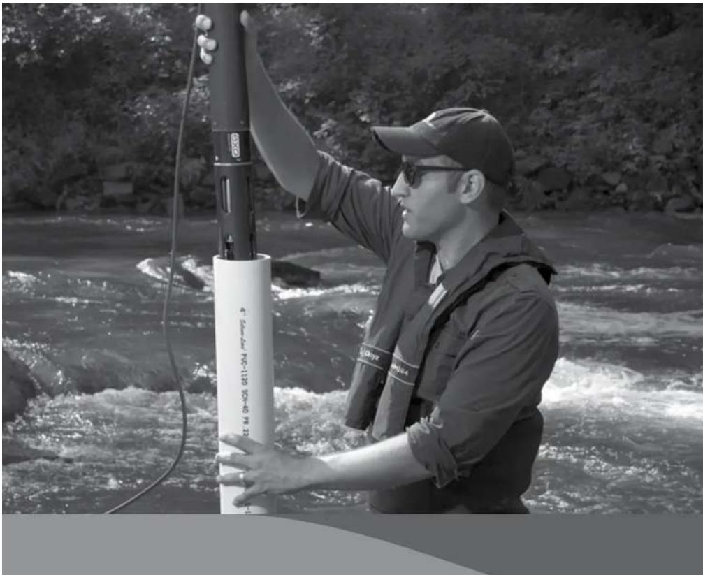
natural_image
Person in life vest and cap working on a river raft with a vertical device (no visible text or symbols)8.1
Vented Level Sonde
Overview
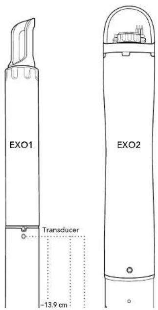
text_image
EXO1 Transducer -13.9 cm EXO2NOTE: EXO3 sondes do not come equipped with a vented level option.
Like EXO depth sensors, level sensors use a differential transducer with one side exposed to the water. However, unlike the depth sensors which have their back side sealed in a vacuum, the other side of the level transducer is vented to the atmosphere.
Because of this venting to the surface the transducer will only measure the water pressure exerted by the water column. Thus, the vented level option for depth measurement eliminates errors due to changes in barometric pressure because the barometric pressure is being seen on both sides of the pressure sensor. This is accomplished by using a special sensor that has been vented to the outside atmosphere by way of a tube that runs through the sonde and cable. This tube must remain open and vented to the outside atmosphere to function. No foreign objects can block the openings.
NOTICE: Never expose the sonde or the cable to the atmosphere for more than a few minutes without an active desiccant or connector dummy plug in place. Moisture or high humidity air entering the vent tubes can condense and block the tube, affecting accuracy; it could also cause damage to the transducer that is
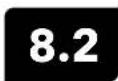
Vented Level Sonde
Installation
When installing a vented level sonde, users must ensure that the sonde never exceeds an operational depth of 10 meters. Provisions for floods, astronomical tides and severe storm events should be factored in.
NOTICE: Exposing the depth sensor to depths greater than 10 meters could result in damage to the pressure sensor that is not covered by the warranty.

natural_image
Pure technical diagram of a mechanical component without any text, numbers, or symbols- Indentation for location or - positioning pin to ensure - consistent horizontal orientation
Location of Depth Sensor
For best measurement accuracy when installing a sonde, the sonde's orientation and position must remain fixed.
When deploying the sonde vertically, take care to ensure the sonde is redeployed in the same position. Use a location pin or suspend the sonde using materials that cannot stretch (chain, wire rope) to ensure a fixed location.
Depth sensors on the EXO2 sondes are not on center. In horizontal deployments, take care to ensure the redeployments are always in the same orientation.
To assist with consistent horizontal orientation, the EXO2 sonde has an indentation at the top of the sonde for a location or positioning pin.
NOTICE: Never band clamp a sonde. This can lead to the sonde body becoming warped and taking on water.
EXO1 Depth Sensor Reference Points (see diagram in Section 8.1)
- From bottom of sensor guard (metal or plastic) to transducer diaphragm: \~34.8 cm / \~13.7 inches
- From face of sensor endcap to transducer diaphragm: -27.2 cm / -10.7 inches
- From face of connector bulkhead to transducer diaphragm: -13.9 cm / -5.5 inches
8.3
Vented Cables and Desiccants
Installation
Cables
Vented cables for EXO have a maximum length of 33 meters, so when connecting a sonde to a data logger, users should use a junction box to reach further distances. In the junction box, the EXO cable can connect to the desiccant, as well as another cable running to the data logger or DCP device.
- Avoid bending vented cables sharply to prevent the inner tube from kinking. (Min. bend radius 20.3 cm/8 in.)
- EXO vented cables have a reduced length to prevent tube damage from their own weight.
- EXO vented cables do not have wet-mate connectors—any water or humidity entering the vent tube will cause damage to the pressure sensor that is not covered by the warranty.
- EXO vented cables are not equipped with the barbed fitting for small desiccant cartridges.
Desiccants
NOTICE: All EXO sondes with vented level require the use of a desiccant. Any damage to the sensor due to the lack of desiccant use is not covered under warranty.
Two desiccant systems are available, a cartridge kit (YSI 6108) and a canister kit (YSI 6109). For all EXO sondes we strongly recommend the 6109 canister kit. The 6109 desiccant canister
text_image
Hose Mounting brackets FittingInstalling YSI 6109 Desiccant Canister
- Remove the 1/8'' NPT plugs from the stainless steel fittings on the canister.
- Install the 1/8" NPT to 1/8" hose fittings into the stainless steel fittings located on the side of the desiccant canister. Do not over-tighten.
- Place the plugs over the fittings on the canister until you are ready to use the canister.
- Using suitable screws fasten the canister mounting brackets to an appropriate support
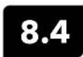
Vented Level Sonde
Calibration
NOTE: This calibration option is available only if your sonde is equipped with a vented level sensor.
For the calibration, make certain that the vented level sensor is in air and not immersed in any solution. Orient the sonde in the same position as it will be deployed. Also, never calibrate a vented level depth sensor with a non-vented cable.
line
| Depth (cm) vs Time | Value | | ----------------- | ----- | | Top | 100 | | Bottom | 50 |In the desktop Kor Calibrate menu, select Depth, then select Depth m to calibrate.
NOTE: If a depth offset is entered, the output value will shift by the value of the offset. Users may use an offset if referencing a water elevation against a known datum.
Observe the Pre Calibration Value readings and the Data Stability, and when they are Stable, click Apply to accept this calibration point. This process zeros the depth sensor.
Click Exit to return to the sensor calibration menu.
For best performance of vented level measurements, users should ensure that the orientation of the sonde remains constant while taking readings. Keep the sonde still and in one position while calibrating.
Advanced
Configure Depth Settings by selecting the Depth Sensor under the Instrument and Sensors menu.
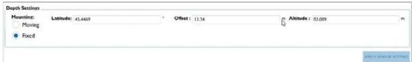
text_image
Depth Settings Mounting: Latitude: 45.4469 Offset: 12.34 Altitude: 82.009 Moving Fixed
Vented Level Sonde
Maintenance and Storage
Short-term Storage
NOTICE: It is important that the air in a sonde's vent tube remains dry at all times.
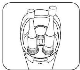
natural_image
Technical line drawing of a mechanical component with three cylindrical parts and concentric rings (no text or symbols)Level Sensor Storage
Users can store these sensors either dry or submerged in clean water. However, regardless of storage method or length, ensure the vent tube remains dry. Always attach the port plug to the cable connector, or leave the cable installed with a cap over the desiccant's vent.
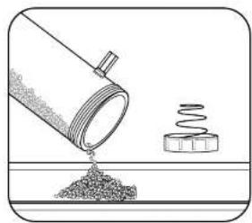
natural_image
Illustration of a pipe pouring granular material into a container with a spring attached (no text or symbols)Level Desiccant Maintenance
Active desiccant is blue; saturated desiccant is pink or rose red. When the desiccant closest to the sonde begins to turn pink, you should replace (YSI 6108), or regenerate (YSI 6109) the desiccant cartridge.
To regenerate desiccant, remove it from the cartridge and heat it for one hour at 200°C (about 400°F); then cool it an airtight container before refilling. Also heat the felt filters at 100°C (about 200°F) for 30 minutes. The desiccant will turn blue following a successful recharge.
Connectors Maintenance
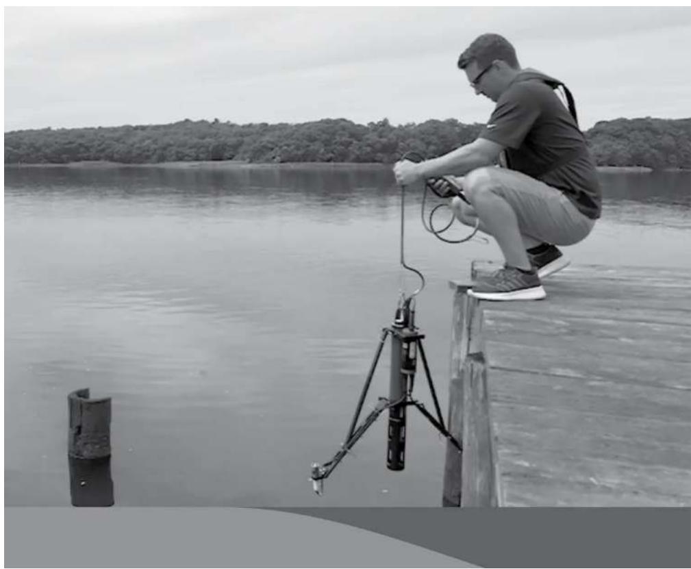
natural_image
Man sitting on a wooden pier using a handheld device near a lake, with a tree-lined shore in the background (no text or symbols visible)9.1
EXO PAR
Introduction
PAR Sensor
Some users of the YSI EXO sonde may wish to incorporate a photosynthetically active radiation (PAR) sensor into their field monitoring equipment. This sensor can be added to the YSI EXO2 sonde in the form of a special adapter engineered by YSI's Integrated System & Services division. This appendix is designed to give potential users of this PAR adapter information on how the system is configured and the steps necessary to acquire and log PAR data with the EXO PAR adapter.
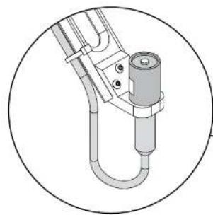
natural_image
Technical line drawing of a mechanical assembly with a cylindrical component and pipe fitting (no text or symbols)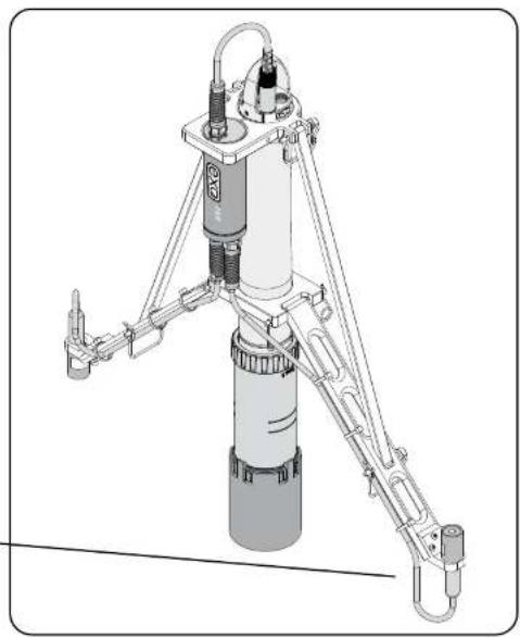
natural_image
Technical line drawing of a mechanical device with articulated arms and a cylindrical body (no text or symbols)C.
Components
The EXO PAR Systems consists of 3 main parts: The EXO PAR adapter cylinder and cables, the black plastic frame system and calibration cup extender, and the Li-Cor PAR sensors.
The EXO PAR system attaches to the EXO2 sonde via an upper and lower clamp system. The EXO PAR adapter attaches to the AUX port on the top bulkhead of the EXO2 sonde.
NOTE: In order for the EXO PAR adapter to be recognized, it must be plugged into the AUX port before applying power to the sondc.
For shipment and storage, the EXO PAR system can fold its sensor and support arms in, along the body of the EXO2 sonde.
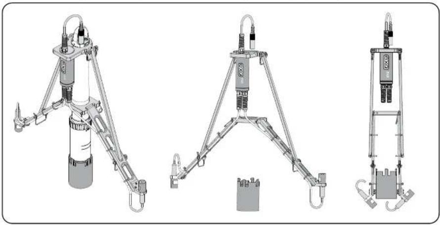
natural_image
Three technical line drawings of a mechanical device with articulated arms and labeled components (no text or symbols present)
EXO PAR
Installation
Attach EXO Calibration Cup Extender
Once you've unpacked the EXO PAR system, attach the EXO calibration cup extender to the bottom of your calibration cup. It simply clicks on by inserting the bottom of the calibration cup into the top of the extender and pushing down on a hard surface.
The calibration cup extender provides you the extra height you will need to prevent your PAR sensors and cables from impacting the ground. It's ideal for in lab use but we recommend using a lab stand as well for stability, to prevent your sonde and PAR system from tipping over and potentially causing damage.

CAUTION: Potential pinch hazard, be mindful of fingers.
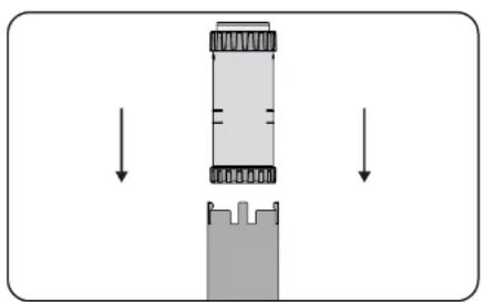
natural_image
Diagram showing a mechanical assembly with downward arrows indicating motion or force direction (no text or symbols)Push down to mate the extender onto the calibration cup.

natural_image
Pure diagram of a vertical structure with internal components, no text or symbols presentThe extender merged with the calibration cup.
- The top of the upper clamp should align with the yellow bulkhead of the sonde (where the blue meets the yellow). Proper alignment is necessary so that the PAR sensor arms are deployed at the correct angle
NOTICE: Proper alignment of clamps is necessary to prevent damage.
natural_image
Technical line drawings of mechanical components, including a spring-loaded assembly and a mounted device with a central component (no text or symbols present)Align the upper clamps with the yellow bulkhead of the sonde
NOTE: In order for the EXO PAR adapter to be recognized, it must be plugged into the AUX port before applying power to the sondo.
- The bottom of the lower clamp should align with the upper edge of the top chamfer on the clear plastic section covered with the black "EXO" sonde label. Again proper alignment is necessary so the PAR sensor arms are deployed so that the PAR sensor faces axis is parallel to the sonde axis.
NOTICE: Proper alignment of clamps is necessary to prevent damage.

natural_image
Pure electrical circuit lines without any symbols- Once you have the EXO PAR system secured to the EXO2 sonde body it is time to deploy the sensor arms. To do so simply lift the arms and install the pins where the two arms meet, as shown.

natural_image
Mechanical linkage diagram showing a chain with springs and connecting rods (no text or labels)Lift the arms and install the pins where the two arms meet

CAUTION: Potential pinch hazard, be mindful of fingers.
- After you have installed the upper and lower clamps, it's time to address cable management. There are two cables that connect to your PAR sensors coming from the EXO PAR adapter cylinder. Supplied with your EXO PAR system will be several black, UV resistant Zip Ties. Fasten the sensor cables to the EXO PAR frame support arms as follows: (3 locations)
NOTE: Dummy plugs are supplied for these cable's connectors, plug these connectors when sensors are removed or if only deploying 1 of your 2 PAR sensors. When not in use, the plugs can be stored in the calibration cup extension.
EXO PAR
Setup
Now that your EXO PAR system is installed, it's time to connect your EXO PAR Sonde to either your PC running Kor Software or your EXO handheld system. For PC applications, you can use the Bluetooth functionality of the EXO to connect with Kor. For EXO handheld applications, you will need to connect an EXO field cable between the EXO communications bulkhead connector and the EXO handheld communications bulkhead connector. The EXO field cable comes in differing lengths depending on your needs, its part number is; 599040-xx (the -xx signifies the cable length; ex -2 equals 2 meters) Cable lengths start at 2 meters.
If the EXO PAR sonde is connecting to a data logger, you can use the EXO flying lead cable, part number 599008-xx (again the xx signifies the cable length) flying lead cables start at 10 meters. You will also need the EXO DCP adapter to connect to a data logger, part number 599820.
Each LI-Cor PAR sensor is supplied with a Certificate of Calibration, shown below. The calibration certificate contains the multipliers for the sensor. YSI uses the in water multiplier for our EXO adapter, providing PAR engineering units out as data. In the following sections, we will review where and how to end this multiplier into either Kor Software or the EXO handheld display.
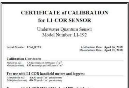
text_image
CERTIFICATE of CALIBRATION for LI-COR SENSOR Underwater Quantum Sensor Model Number: LI-192 Serial Number: UWQ0723 Calibration Date: April 06, 2018 Manufacture Date: April 05, 2018 Calibration Constants: Output (in-air): 7.3 micrometers per 1000 μmol s⁻¹ m⁻² Output (in-worst): 5.53 micrometers per 1000 μmol s⁻¹ m⁻² For use with LI-COR handheld meters and loggers: Multiplier (in-air) : -136.53 μmol s⁻¹ m⁻² per micromap Multiplier (in-worst) : -180.75 μmol s⁻¹ m⁻² per micromapSetup Kor Software
In the following steps we will cover the setup of the PAR sensor utilizing the YSI Kor software.
- You will first need to enable the PAR(s) sensor in Kor. To do so you will need to select File, and then select Settings, and from the list of parameters select PAR and you will see the screen below if done correctly. From this window you can enable either the PAR sensor or sensors by clicking the boxes shown.

text_image
Settings General Settings Algae Parameter Constructing Chromosome Depth IDOM GPS ISO GO ORP PAS pH Radiamine WT NetsLED Snads Temperature Turbidity Wiper CAM Channel 1 (nmol l⁻¹ m⁻¹) On Channel 2 (nmol l⁻¹ m⁻¹) On View Unit Data ProDIGITAL Handheld Visit University OK Cancel PRODIGITAL HANDIBLES UNIFORMS UNIFORMS UNIFORMS UNIFORMS UNIFORMS UNIFORMS UNIFORMS UNIFORMS UNIFORMS UNIFORMS UNIFORMS UNIFORMS UNIFORMS UNIFORMS UNIFORMS UNIFORMS UNIFORMS UNIFORMS UNIFORMS UNIFORMS UNIFORMS UNIFORMS UNIFORMS UNIFORMS UNIFORMS UNFORMS UNFORMS UNFORMS UNFORMS UNFORMS UNFORMS UNFORMS UNFORMS UNFORMS UNFORMS UNFORMS UNFORMS UNFORMS UNFORMS UNFORMS UNFORMS UNFORMS UNFORMS UNFORMS UNFORMS UNFORMS UNFORMS UNFORMS UNFORMS UNFORMS UNORMS UNFORMS UNFORMS UNFORMS UNFORMS UNFORMS UNFORMS UNFORMS UNFORMS UNFORMS UNFORMS UNFORMS UNFORMS UNFORMS UNFORMS UNFORMS UNFORMS UNFORMS UNFORMS UNFORMS UNFORMS UNFORMS UNFORMS UNFORMS UNFORMS UNFINES PRODIGITAL HANDIBLES PRODIGITAL HANDIBLES PRODIGITAL HANDIBLES PRODIGITAL HANDIBLES PRODIGITAL HANDIBLES PRODIGITAL HANDIBLES PRODIGITAL HANDIBLES PRODIGITAL HANDIBLES PRODIGITAL HANDIBLES PRODIGITAL HANDIBLES PRODIGITAL HANDIBLES PRODIGITAL HANDIBLES PRODIGITAL HANDIBLES PRODIGITAL HANDIBLES PRODIGITAL HANDIBLES ProDIGITAL HANDIBLES PRODIGITAL HANDIBLES PRODIGITAL HANDIBLES PRODIGITAL HANDIBLES PRODIGITAL HANDIBLES PRODIGITAL HANDIBLES PRODIGITAL HANDIBLES PRODIGITAL HANDIBLES PRODIGITAL HANDIBLES PRODIGITAL HANDIBLES PRODIGITAL HANDIBLES PRODIGITAL HANDIBLES PRODIGITAL HANDIBLES PRODIGITAL HANDIBLES PRODIGATAL HANDIBLE S PRODIGATAL HANDIBLE S PRODIGATAL HANDIBLE S PRODIGATAL HANDIBLE S PRODIGATAL HANDIBLE S PRODIGATAL HANDIBLE S PRODIGATAL HANDIBLE S PRODIGATAL HANDIBLE S PRODIGATAL HANDIBLE S PRODIGATAL HANDIBLE S PRODIGATAL HANDIBLE S PRODIGATAL HANDIBLE S PRODIGATAL HANDIBLE S PRODIGATAL HANDIBLE S PRODIGATAL HANDIBLE S ProDIGATAL HANDIBLE S PRODIGATAL HANDIBLE S PRODIGATAL HANDIBLE S PRODIGATAL HANDIBLE S PRODIGATAL HANDIBLE S PRODIGATAL HANDIBLE S PRODIGATAL HANDIBLE S PRODIGATAL HANDIBLE S PRODIGATAL HANDIBLE S PRODIGATAL HANDIBLE S PRODIGATAL HANDIBLE S PRODIGATAL HANDIBLE S PRODIGATAL HANDIBLE S PRODIGATAL HANDIBLE S PRODIGITAL HANDIBLE S PRODIGITAL HANDIBLE S PRODIGITAL HANDIBLE S PRODIGITAL HANDIBLE S PRODIGITAL HANDIBLE S PRODIGITAL HANDIBLE S PRODIGITAL HANDIBLE S PRODIGITAL HANDIBLE S PRODIGITAL HANDIBLE S PRODIGITAL HANDIBLE S PRODIGITAL HANDIBLE S PRODIGITAL HANDIBLE S PRODIGITAL HANDIBLE S PRODIGITAL HANDIBLE S PRODIGITAL HANDIBERSEnable the PAR sensor in Kor

text_image
HOME CALIBRATION DOCUMENT Device Status Overall System QC Score - Signal Number: (2196190) Framework Version: 1.0K Configuration: EXCO if part fails One Spces User: 8000 Coordactivity Sensor Red blood Part Number : 1 Serial Number : QH11E1787 Framework Version : 50.8 DO Sensor Red blood Part Number : 1 Serial Number : QH11E174 Framework Version : 50.8 PAR Sensor Red blood Part Number : 1 Serial Number : RIN180003 Framework Version : 1.05 Ducts Sensor Red blood Part Number : 1 Serial Number : DZ018140 Framework Version : 50.8 Latest Calibration Data for the Following Sensor: PAR PAR Settings Channel 1 Multiplier (unitless * cm * per μL) : -284.04 Channel 2 Multiplier (unitless * cm * per μL) : -327.01Enter the multipliers into Kor software.
- Now your PAR sensor(s) are ready to use. You can now see PAR data begin to show up in your Kor Dashboard.
text_image
HOME CALIBRATION DEVELOPMENT LINE DATA RECORDED DATA INSTRUMENT AND SENSORS Live DataSetup the EXO Handheld Display
In the following section we will cover setting up EXO PAR utilizing the EXO Handheld Display.
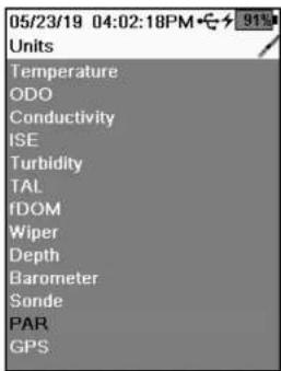
text_image
05/23/19 04:02:18PM 91% Units Temperature ODO Conductivity ISE Turbidity TAL fDOM Wiper Depth Barometer Sonde PAR GPSSelect PAR from the list of Units
- You will first need to enable the PAR sensor(s) in the EXO Handheld. To do so you will need to select Handheld, and then select Display, and from the list of Units select PAR.

Enable sensors
- On the next screen you can enable either the PAR sensor or sensors by clicking the boxes shown.
- Using the Calibration Certificate supplied with your Li-Cor PAR sensor, you will now enter the multipliers into EXO Handheld
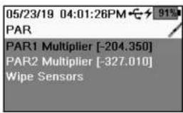
text_image
05/23/19 04:01:26PM PAR PAR1 Multiplier [-204.350] PAR2 Multiplier [-327.010] Wipe SensorsEnter the multipliers exactly as they are on the certificates
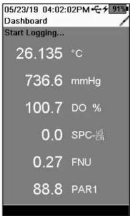
text_image
05/23/19 04:02:02PM Dashboard Start Logging... 26.135 °C 736.6 mmHg 100.7 DO % 0.0 SPC-US 0.27 FNU 88.8 PAR1PAR data on EXO Handheld Display
-
From the Calibration Certificate you will use the In Water multiplier that is listed under the Handheld Meters and Loggers section. You will enter the multipliers exactly as they are on the certificates in the fields shown for Channel 1 and Channel 2 shown. If you are only using one PAR sensor, the default channel will be Channel 1. Leave the default value in Channel 2, which will be (1).
-
Now your PAR sensor(s) are ready to use. You can now see PAR data begin to show up in your EXO Handheld Display.
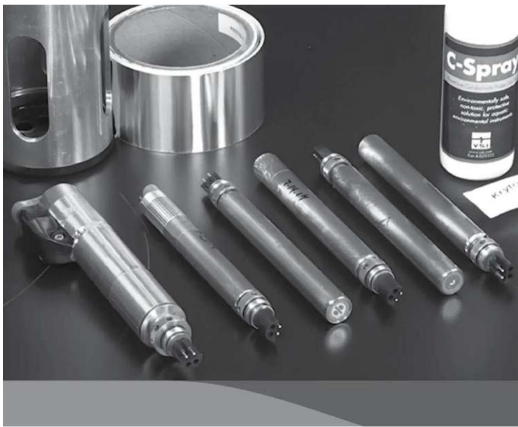
natural_image
Black-and-white photo of various industrial spray tubes and a C-Spray container on a dark surface (no visible text or symbols)10.1
Ordering EXO Sondes and Accessories
Telephone: 800 897 4151 (USA)
+1 937 767 7241 (Globally) Monday through Friday, 8:00
AM to 5:00 ET
Fax: +1 937 767 9353 (orders)
Email: info@ysi.com
Mail: YSI Incorporated 1725 Brannum Lane
Yellow Springs, OH 45387 USA
Y\$I.com
When placing an order please have the following available:
- YSI account number (if available)
- Name and phone number
- Purchase Order or Credit Card number
- Model Number or brief description
- Billing and shipping addresses
- Quantity
EXO1 Sondes
| YSI Item # Description |
| 599501-00 EXO1 Sonde, No Depth, 4 Sensor Ports |
| 599501-01 EXO1 Sonde, 10 meter Depth, 4 Sensor Ports |
| 599501-02 EXO1 Sonde, 100 meter Depth, 4 Sensor Ports |
| 599501-03 EXO1 Sonde, 250 meter depth, 4 Sensor Ports |
| 599501-04 EXO1 Sonde, 10 meter vented level depth, 4 Sensor Ports |
| 577501-00 EXO1 ^§ Sonde, No Battery, No Depth, 4 Sensor Ports |
| 577501-01 EXO1 ^§ Sonde, No Battery, 10 meter Depth, 4 Sensor Ports |
| 577501-02 EXO1 ^§ Sonde, No Battery, 100 meter Depth, 4 Sensor Ports |
| 577501-03 EXO1 ^§ Sonde, No Battery, 250 meter Depth, 4 Sensor Ports |
EXO2 Sondes
| YSI Item # Description |
| 599502-00 EXO2 Sonde, No Depth, 7 Sensor Ports, Central Wiper Compatible |
| 599502-01 EXO2 Sonde, 10 meter depth, 7 Sensor Ports, Central Wiper Compatible |
| 599502-02 EXO2 Sondc, 100 meter depth, 7 Sensor Ports, Central Wiper Compatible |
| 599502-03 EXO2 Sonde, 250 meter depth, 7 Sensor Ports, Central Wiper Compatible |
| 599502-04 EXO2 Sondc, 10 meter-vested level depth, 7 Sensor Ports, Central Wiper Compatible |
509502 04 EVO2 Condo 10 motor-vented level depth 7 Cancer Porto Control Wires Compostible
EXO Handheld
| YSI Item # Description |
| 599960 EXQ Handheld Display |
EXO GO
| YSI Item # Description |
| 577400 EXO GO Bluetooth Adapter |
EXO Signal Output Adapters
| YSI Item # Description |
| 599820 EXO Signal Output Adapter - Data Collection Platform (DCP) 2.0 |
| 599825 EXO Signal Output Adapter - Modbus |
| 599810 EXO Signal Output Adapter - USB (Necessary for firmware updates.) |
EXO Cables
| YSI Item # Description |
| 599040-2 EXO 2 meter Field Cable |
| 599040-4 EXO 4 meter Field Cable |
| 599040-10 EXO 10 meter Field Cable |
| 599040-15 EXO 15 meter Field Cable |
| 599040-33 EXO 33 meter Field Cable |
| 599040-66 EXO 66 meter Field Cable |
| 599040-100 EXO 100 meter Field Cable |
| 599040-150 EXO 150 meter Field Cable |
| 599040-200 EXO 200 meter Field Cable |
| 599040-250 EXO 250 meter Field Cable |
| 599040-300 EXO 300 meter Field Cable |
| 599008-10 EXO 10 meter Flying Lead Cable |
| 599008-15 EXO 15 meter Flying Lead Cable |
| 599008-33 EXO 33 meter Flying Lead Cable |
| 599008-66 EXO 66 meter Flying Lead Cable |
EXO Sensors & EXO Central Wiper
| YSI Item # Description |
| 599870 EXO Conductivity/Temperature Sensor |
| 599827 EXO Wiped Conductivity/Temperature Sensor |
| 577601 EXO pH Sensor Assembly, Guarded |
| 577611 EXO pH/ORP Sensor Assembly, Guarded |
| 577602 EXO pH Sensor Assembly, Unguarded |
| 577612 EXO pH/ORP Sensor Assembly, Unguarded |
| 599710 EXO Ammonium Sensor Assembly,Guarded |
| 599711 EXO Chloride Sensor Assembly, Guarded |
| 599709 EXO Nitrate Sensor Assembly, Guarded |
YSI Item # Description
| 599100-01 EXO Optical DO Sensor |
| 599101-01 EXO Turbidity Sensor |
| 599102-01 EXO Total Algae - PC Sensor |
| 599103-01 EXO Total Algae - PE Sensor |
| 599104-01 EXO fDOM Sensor |
| 577614 EXO Rhodamine Sensor |
| 599090-01 EXO Central Wiper |
| 608040 EXO NitraLED Sensor |
| 608090 EXO NitraLED Sensor Kit |
EXO Replaceable Sensor Tips
| YSI Item # Description |
| 577603-01 EXO pH Sensor Replacement Module, Guarded (User replaceable tip for 577601) |
| 577603-02 EXO pH Sensor Replacement Module, Un-Guarded (User replaceable tip for 577602) |
| 577613-01 EXO pH/ORP Sensor Replacement Module, Guarded (User replaceable tip for 577611) |
| 577613-02 EXO pH/ORP Sensor Replacement Module, Un-Guarded (User replaceable tip for 577612) |
| 599744-01 EXO Ammonium Sensor Replacement Module, Guarded (User replaceable tip for 599710) |
| 599743-01 EXO Nitrate Sensor Replacement Module, Guarded (User replaceable tip for 599709) |
| 599745-01 EXO Chloride Sensor Replacement Module, Guarded (User replaceable tip for 599711) |
EXO PAR
| YSI Item # Description |
| 351070 EXO PAR Adapter Assembly |
| 351073 EXO PAR, Upper Clamp |
| 351074 EXO PAR, Lower Clamp |
| 351075 EXO PAR, Wide Extension Arm (Lower) |
| 351076 EXO PAR, PAR Sensor Bracket |
| 351077 EXO PAR, Narrow Extension Arm (Upper) |
| 351087 EXO PAR, Clip-on Calibration Cup Extender |
EXO General Accessories
| VOLI. II | B. 1.1 | VOLI. II | B. 1.1 |
EXO Anti-fouling Accessories
| YSI Item # Description |
| 599867 EXO Anti Fouling C/T Screen |
| 599563 EXO1 Anti-Fouling Guard |
| 599564 EXO2 / EXO3 Anti-Fouling Guard |
| 599663 EXO2 / EXO3 Probe and Sonde protective sleeves |
| 6189-AF Copper tape kit |
| C-SPRAY Protective probe solution, 100 mL bottle |
Calibration Standards and Solutions
| YSI Item # Description | YSI Item # | Description | |
| 065270 Conductivity Cal. - 1,000 umhos/cm (quart) | 003821 | pH 4 Buffer - Box of 6 pints | |
| 065272 Conductivity Cal. - 10,000 umhos/cm (quart) | 003822 | pH 7 Buffer - Box of 6 pints | |
| 065274 Conductivity Cal. - 100,000 umhos/cm (quart) | 003823 | pH 10 Buffer - Box of 6 pints | |
| 060907 Conductivity Cal. - 1,000 umhos/cm (8 ea, pint) | 603824 | Assorted pH Buffers - 2 pints of 4 - 2 pints of 7 - 2 pints of 10* | |
| 060911 Conductivity Cal. - 10,000 umhos/cm (8 ea, pint) | 003841 | Ammonium Cal Solution - 1 mg/L (500 mL) | |
| 060660 Conductivity Cal. - 50,000 umhos/cm (8 ea, pint) | 003842 | Ammonium Cal Solution - 10 mg/L (500 mL) | |
| 061320 Zobell Solution - For ORP cal. - 125 mL | 003843 | Ammonium Cal Solution - 100 mg/L (500 mL) | |
| 061321 Zobell Solution - For ORP cal. - 250 mL | 003885 | Nitrate Standard - 1 mg/L (500 mL) | |
| 061322 Zobell Solution - For ORP cal. - 500 mL | 003886 | Nitrate Standard - 10 mg/L (500 mL) | |
| 608072 NitraLED Calibration Standard - 5 mg/L | 003887 | Nitrate Standard - 100 mg/L (500 mL) | |
| 608000 | Turbidity Std. - 0 NFU, 0 NTU - 1 Gallon | ||
| 607200 | Turbidity Std. - 12.4 FNU - 1 Gallon | ||
| 607300 | Turbidity Std. - 124 FNU - 1 Gallon | ||
| 608073 NitraLED Calibration Standard - 10 mg/L | 607400 | Turbidity Std. - 1010 FNU - 1 Gallon | |

natural_image
Black-and-white photo of miniature workers in hard hats inspecting a circuit board (no text or symbols visible)
Health and Safety
Chemicals
NOTE: For additional health, safety, and disposal information about reagents, download the MSDS documents for the chemical in question from the EXO manufacturers' websites: www.vsi.com or www.wtw.de.
First Aid for all solutions
| Inhalation | Move to fresh air. If breathing is difficult, give oxygen. If symptoms persist, seek medical attention. |
| Skin Contact | Remove contaminated clothing and wash.Wash exposed area with soap and water for at least 15 minutes.If irritation persists, seek medical attention. |
| Eye Contact | Rinse eyes immediately with large amounts of water, also under eyelids, for at least 15 minutes. If irritation persists, seek medical attention. |
| Ingestion | Wash out mouth with water and then drink plenty of water. If symptoms persist, seek medical attention. |
Ammonium Solutions
3841, 3842, and 3843
Ingredients: Water, Ammonium Chloride, Lithium Acetate Dihydrate, Sodium Azide, Hydrochloric Acid
Nitrate Solutions
3885, 3886, and 3887
Ingredients: Water, Potassium Nitrate, Magnesium Sulfate Heptahydrate, Gentamycin Sulfate
Inhalation: Avoid breathing vapors or mists. Ensure adequate ventilation is available before handling.
Skin: Wear lightweight protective clothing, gloves, and apron.
Eyes: Wear safety glasses with side-shields or face shield. Contact lenses should not be worn when working with these solutions.
Ingestion: May be harmful if swallowed. Wear a mouth cover or face shield when there is splashing. Keep away from food and drink.
First Aid: See box at left.
Conductivity Solutions
3161, 3163, 3165, 3167, 3168, and 3169
Ingredients: Water, Potassium Chloride
Inhalation: Avoid breathing urea or mica. Inhalation of dust may cause irritation
pH 4.00, 7.00, 10.00 Buffer Solutions
3821, 3822, and 3823
pH 4 Ingredients: Water, Potassium Hydrogen Phthalate, Red food coloring
pH 7 Ingredients: Water, Potassium Phosphate Monobasic, Sodium Hydroxide, Yellow food coloring
pH 10 Ingredients: Water, Potassium Hydroxide, Disodium EDTA dihydrate, Potassium Borate, Potassium Carbonate, Bromphenol Blue Sodium Salt, Bromphenol Green Sodium Salt
Inhalation: Avoid breathing vapors or mists. Inhalation of dust may cause irritation of respiratory tissues. Ensure adequate ventilation is available before handling.
Skin: Exposure may cause irritation with repeated exposure. Wear rubber or neoprene gloves.
Eyes: Can cause irritation and potential eye damage with repeated exposure. Wear safety glasses with side-shields or face shield. Contact lenses should not be worn when working with these solutions.
Ingestion: May cause nausea, vomiting, or diarrhea. Wear a mouth cover or face shield when there is splashing. Do not swallow. Do not induce vomiting.
First Aid: See First Aid table.
Zobell Solution
3682
Ingredients: Potassium Chloride, Potassium Ferrocyanide Trihydrate, Potassium Ferricyanide
Inhalation: Inhalation of dust may cause irritation of respiratory tissues. Ensure adequate ventilation is available before handling.
Skin: Exposure may cause irritation. Wear lightweight protective clothing, gloves, boots, and apron.
Eyes: May cause irritation. Wear safety glasses with side-shields or face shield.
Ingestion: May cause an upset stomach. Wear a mouth cover or face shield when there is splashing. Keep away from food and drink. Do not swallow. If large amount is ingested and person is conscious, induce vomiting.
First Aid: See First Aid table.
Ultraviolet Light
The fDOM and NitraLED sensors radiates ultraviolet light (UV light) which can be harmful to the eyes even during brief periods of exposure. Do not look into the light at the tip of the probe and wear protective eyewear when handling UV LEDs.
Lithium-Ion Battery Handling

WARNING: Failure to exercise care when handling this product and to comply with the following conditions and guidelines could result in product malfunction, excessive heat, fire, property damage, and ultimately injury.
- DO NOT alter, puncture, or impact battery or related components.
• DO NOT directly connect the terminals with metal objects.
- DO NOT expose the battery to extreme temperatures or direct extended exposure to sunlight.
• Always disconnect batteries when not in use and for long term storage.
- Store batteries in a non-conductive and fireproof container.
- For best results, store the battery at approximately 50% of the capacity.
If at any time the battery becomes damaged, hot, or begins to balloon or swell, discontinue charging (or discharging) immediately. Quickly and safely disconnect the charger. Then place the battery and/or charger in a safe, open area way from flammable materials. After one hour of observation, remove the battery from service. DO NOT continue to handle, attempt to use, or ship the battery. Failure to follow these procedures can cause damage to the battery, personal property or cause serious injury.
Damaged or swollen batteries can be unstable and very hot. DO NOT touch batteries until they have cooled. In the event of a fire use a Class A, B, or C fire extinguisher. DO NOT use water.
If the internal battery fluid comes into contact with your skin, wash the affected area(s) with soap and water immediately. If it comes into contact with your eye(s), flush them with generous amounts of water for 15 minutes and seek immediate medical attention.
11.2
Radio Frequency
Xylem certifies that the EXO product line has been tested and complies with the following radio frequency (RF) interference standards and are approved for use in the following countries:
• United States: FCC Part 15 compliant
• Canada: RSS compliant
• European Union (EU): CE compliant
• Australia: CISPR 11 compliant
• New Zealand: CISPR 11 compliant
• Republic of Korea: Radio Waves Act compliant
• Japan: TELEC Radio Law compliant
• Brazil: Anatel certification compliant
Reference the Declaration of Conformity in the next section for further details.
Bluetooth wireless technology and similar approvals and regulations can be country-specific. Check local laws and

regulations to insure that the use of wireless products purchased from Xylem or its subsidiaries are in full compliance.
11.3 Declarations of Conformity
The undersigned hereby declares that the products listed below conform with all applicable requirements of FCC Part 15 for the U.S. and Industry Canada (IC) ICES-003 for Canada.
Manufacturer: YSI Incorporated, a Xylem brand
1725
Brannum
Lane
Yellow Springs, OH 45387 USA
Equipment name: EXO Sondes (EXO1, EXO2 and EXO3), EXO Handheld (V2) and EXO GO
Model numbers: 599501-xx, 599502-xx, 599503-xx, 599960, 577400
Intentional Radiators: EXO Sondes (EXO1, EXO2 and EXO3) contain a Bluetooth module:

FCC
ID
216Q-PAN10
EXO GO contains a Wi-Fi/Bluetooth module:
FCC
ID:
6514A-RN42
Regulations: • FCC 47 CFR Part 15

IC
ICES-003

Gregory Popo/Quality Manager
January 14 ^th , 2019
The undersigned hereby declares that the products listed below conform to all applicable Essential Requirements of the listed Directives and carry the CE mark accordingly.
Manufacturer: YSI Incorporated, a Xylem brand
1725 Brannum Lane
Yellow Springs, OH 45387 USA
Equipment name: EXO Sondos (EXO1, EXO2 and EXO3), EXO Handheld (v2) and EXO GO
Model numbers: 599501-xx, 599502-xx, 599503-xx, 599960, 577400, 577502-xx, 577503-xx
Accessories/Sensors: 57760x-(xx), 57761x-(xx), 599008-xx(x), 599020-xx, 599040-xx(x), 599080,
599090-xx, 59910x-xx, 599110, 599210, 599316, 599357, 599431-xx,
599469, 59947x, 59952x, 599555, 59956x, 59959x, 5996xx, 5997xx-(xx),
5998xx, 599951-xx, 608040, 608080, 608085
Intentional Radiators: EXO Sondes (EXO1, EXO2 and EXO3) contain a Bluetooth module.

The EXO GO (577400) contains a Bluetooth module.
Nemko Certified Body ID#CE 2302.
Directives:
•EMC 2014/30/EU •RED 2014/53/EU •LVD 2014/35/EU REACH (EC) No. 1907/2006
•R&TTE 1999/5/EC •WEEE 2012/19/EU •RoHS 2011/65/EU
Harmonized Standards:
• EN61326-1:2013, Electrical equipment for measurement, control and laboratory use -
EMC requirements - Part 1: General requirements
• EN 61326-2-3:2013, Electrical equipment for measurement, control and laboratory use - EMC requirements -
Part 2-3: Particular requirements - Test configuration, operational conditions and performance criteria for transducers with integrated or remote signal conditioning
• EN 60950-1:2006 + A11:2009 + A12:2011 + A1:2010 + A2:2013, Information technology equipment - Safety -
Part 1: General requirements
- EN 300 328 V2.1.1:2017, Wideband transmission systems; Data transmission equipment operating in the 2,4 GHz ISM band and using wide band modulation techniques; Harmonized Standard covering the essential requirements of article
The undersigned hereby declares that the products listed below conform with the Australian and New Zealand Electromagnetic Compatibility (EMC) requirements for generic products to be used in residential, commercial, and light industrial environments, and carry the C-Tick mark accordingly.
Manufacturer: YSI Incorporated, a Xylem brand 1725 Brannum Lane Yellow Springs, OH 45387 USA
Equipment name: EXO Sondes (EXO1, EXO2 and EXO3), EXO Handheld (v2) and EXO GO Model numbers: 599501-xx, 599502-xx, 599503-xx, 599960, 577400
Accessories/Sensors: 599090-xx, 599100-xx, 599101-xx, 599102-xx, 599104-xx, 599118-xx, 599800, 599810, 599870, 599040-xx, 599008-xx, 577641
Intentional Radiators: EXO Sondes (EXO1, EXO2 and EXO3) contain a Bluetooth module.
EXO GO (577400) contains a Bluetooth module. Nemko Certified Body ID#CE 2302.
Regulations:
• Australian ACMA Standards for C-Tick mark, Section 182 of the Radiocommunications Act 1992.
• New Zealand RSM Standards, Radiocommunications Act 1992.
• Telecommunications Labeling, Notice 2001 under section 407 of the Australian Telecommunications Act 1997.
Standards:
- EN61326-1:2006, Electrical equipment for measurement, control, and laboratory use - EMC requirements - Part 1: General Requirements.
• ACMA Radio Communications (Short Range Devices), 2004.
• AS/NZ 4268, 2008.
• Radio Communications (Electromagnetic Radiation - Human Exposure) Standard, March 2003.

Gregory Ponn Quality Manager
The undersigned hereby declares that the products listed below conform with all applicable requirements of the Radio Waves Act of Korea, for intentional radiators.
Manufacturer: YSI Incorporated, a Xylem brand
1725
Brannum
Lane
Yellow Springs, OH 45387 USA
Equipment name: EXO Sondes (EXO1, EXO2 and EXO3) and EXO GO
Model numbers: 599501-xx, 599502-xx, 599503-xx, 577400
Intentional Radiators: EXO Sondes (EXO1, EXO2 and EXO3) contain the PAN1026 Bluetooth module.
Broadcasting and certification number R-C-XYL-EXO1 (for EXO1), R-C-XYL-EXO2 (for EXO2) and R-C-XYL-EXO3-PAN1026 (for EXO3).
EXO GO (577400) contains a Bluetooth module. Broadcasting and certification number KCC-CRI-AEP-RN-42.
Type Identification: LARN8-IO2Y2402/2480TR0.000003F1D79 (EXO1)
LARN8-IO2Y2402/2480TR0.00001F1D79(EXO2)
LARN8-IO2Y2402/2480TR0.001F1D79
(EXO3)
LARN8-IO2Y2402/2480TR0.00003F1DG1D79 (EXO Handheld)
Regulation: Radio Waves Act of the Republic of Korea.
Class A device (Broadcasting and communication equipment for office work).
Seller and user shall be noticed that this equipment is suitable for electromagnetic equipment for office work (Class A) and it can be used outside the home.
KCC notice 2012-12. Radio device using 2400-2483.5 MHz and 5725-5825 MHz.
The undersigned hereby declares that the products listed below conform with all applicable requirements of the Radio Regulations of China, for intentional radiators.
Manufacturer: YSI Incorporated, a Xylem brand
1725
Brannum
Lane
Yellow Springs, OH 45387 USA
Equipment name: EXO Sondes (EXO1, EXO2 and EXO3) and EXO GO
Model numbers: 599501-xx, 599502-xx, 599503-xx, 577400
Intentional Radiators: The EXO GO (577400) contains a Bluetooth module.

CMIIT ID: CMIIT ID: 2018DJ6806 (EXO1, EXO2, EXO3)
CMIIT ID: 2018DJ2145 (EXO GO)
Regulation: Radio Regulations of the People's Republic of China.
A级设备(办公用广播和通讯设备)
Class A device (Broadcasting and communication equipment for office work).
Seller and user shall be noticed that this equipment is suitable for electromagnetic equipment for office work (Class A) and it can be used outside the home.

Gregory Popp, Quality Manager
June 12 ^th , 2020
The undersigned hereby declares that the products listed below conform with all applicable requirements of TELEC and Radio Law of Japan for intentional radiators.
Manufacturer: YSI Incorporated, a Xylem brand
1725
Brannum
Lane
Yellow Springs, OH 45387 USA
Equipment name: EXO Sondes (EXO1, EXO2 and EXO3) and EXO GO
Model numbers: 599501-xx, 599502-xx, 599503-xx, 577400
Intentional Radiators: EXO Sondes contain transmitter module with certification number:

MIC
ID:
[R]202-LSE095
EXO GO contains transmitter module with certification number:
MIC
ID:
[R]201-125709
Regulations: TELEC; Article 38-24 Paragraph 1 of the Radio Law.
Gregory Popp, Quality Manager
January 14 ^th , 2019
The undersigned hereby declares that the products listed below conform with all applicable requirements of the Anatel Regulations of Brazil for intentional radiators.
Manufacturer: YSI Incorporated, a Xylem brand
1725
Brannum
Lane
Yellow Springs, OH 45387 USA
Equipment name: EXO Sondes (EXO1, EXO2 and EXO3) and EXO GO
Model numbers: 599501-xx, 599502-xx, 599503-xx, 577400
Intentional Radiators: Intentional Radiators: EXO Sondes (EXO1, EXO2 and EXO3) contain the
PAN1026 Bluetooth module: Certificate of Homologation No. 01640-18-08838;
Certificate of Conformity No. 00106288.
EXO GO (577400) contains the RN42 Bluetooth module:
Certificate of Homologation No. 00436-18-08838;
Certificate of Conformity No. 00099335.
Regulations: Anatel; Transceptor de Radiacao Restrita - Categoria II

Gregory Popp, Quality Manager
January 14 ^th , 2019
11.4 Instrument Warranty
Warranty Card
Register your product with the online warranty card: www.YSI.com/warranty
Warranted against defects in workmanship and materials when used for their intended purposes and maintained according to instructions and exclusive of batteries and any damage caused by defective batteries.
Two years: cables; conductivity, temperature, depth, and optical sensors; electronics base for pH, pH/ORP, ammonium, chloride, and nitrate sensors; and accessories
One year: optical DO membranes and replaceable reagent modules for pH and pH/ORP; EXO GO
Three months: replaceable reagent modules for ammonium, chloride, and nitrate
Regular maintenance of sondes and sensors, such as replacing damaged o-rings, is described in the Maintenance section of this manual. Users are expected to follow these guidelines to keep their equipment in good and proper working order and to protect the warranty on the product. Damage due to accidents, misuse, tampering, or failure to perform prescribed maintenance is not covered.
This warranty does not include batteries or damage resulting from defective batteries. As documented in the Maintenance section of this manual, batteries should be removed from all sondes and handheld when the product is not in use. Since many battery manufacturers will repair or replace any equipment that has been damaged by their batteries, it is essential that leaky or defective batteries be retained with the damaged product until the manufacturer has evaluated the claim.
Product(s) must be sold by and received from Xylem or an authorized representative or distributor. The warranty period starts when the instrument is received. The warranty period for chemicals and reagents is determined by the expiration date printed on their labels. Within the warranty period, we will repair or replace, at our sole discretion, free of charge, any product that we determine to be covered by this warranty.
To exercise this warranty, write or call your local representative, or contact Technical Support. Send the product and proof of purchase, transportation prepaid, to the Authorized Service Center selected by the manufacturer. Repair or replacement will be made and the product returned transportation prepaid. Repaired or replaced products are warranted for the balance of the original warranty period, or at least 90 days from date of repair or replacement.
11.5
Instrument Service
Cleaning and Packing
Product Return Form
Find the product return form online: www.YSI.com/Repair
Cleaning Instructions
Before they can be serviced, equipment exposed to biological, radioactive, or toxic materials must be cleaned and disinfected. Biological contamination is presumed for any instrument, probe, or other device that has been used with body fluids or tissues, or with wastewater. Radioactive contamination is presumed for any instrument, probe or other device that has been used near any radioactive source.
Cleaning Certificate
Find the cleaning certificate on the back of the online product return form: www.YSI.com/Repair
If an instrument, probe, or other part is returned or presented for service without a Cleaning Certificate, and if in our opinion it represents a potential biological or radioactive hazard, our service personnel reserve the right to withhold service until appropriate cleaning, decontamination, and certification has been completed. We will contact the sender for instructions as to the disposition of the equipment. Disposition costs will be the senders responsibility.
When service is required, either at the user's facility or at the manufacturer, the following steps must be taken to insure the safety of our service personnel:
- In a manner appropriate to each device, decontaminate all exposed surfaces, including any containers. 70% isopropyl alcohol or a solution of 1/4 cup bleach to 1 gallon tap water are suitable for most disinfecting. Instruments used with wastewater may be disinfected with .5% Lysol® if this is more convenient to the user.
- The user shall take normal precautions to prevent radioactive contamination and must use appropriate decontamination procedures should exposure occur.
- If exposure has occurred, the customer must certify that decontamination has been accomplished and that no radioactivity is detectable by survey equipment.
- Cleaning must be completed and certified on any product before returning.
11.6
Instrument Service
Recycling
Batteries
The user must remove and dispose of alkaline batteries when they no longer power the EXO1 sonde, EXO2 sonde, or EXO Hand-held. Disposal requirements vary by country and region, and users are expected to understand and follow the battery disposal requirements for their specific locale.
The circuit board in these instruments may contain a manganese dioxide lithium "coin cell" battery that must be in place for continuity of power to memory devices on the board. This battery is not user serviceable or replaceable. When appropriate, an authorized service center will remove this battery and properly dispose of it, per service and repair policies.
Rechargeable Li-Battery Pack
(1) When the battery is worn out, insulate the terminals with adhesive tape or similar materials before disposal.
(2) Dispose of batteries in the manner required by your city, county, state or country. For details on recycling lithium-ion batteries, please contact a government recycling agency, your waste-disposal service, or visit reputable online recycling sources such as www.batteryrecycling.com.
This product must not be disposed of with other waste. Instead, it is the user's responsibility to dispose of their waste equipment by handing it over to a designated collection point for the recycling of waste electrical and electronic equipment. The separate collection and recycling of your waste equipment at the time of disposal will help to conserve natural resources and ensure that it is recycled in a manner that protects human health and the environment.
For more information about where you can drop off your waste equipment for recycling, please contact your local city office, or your household waste disposal service. DO NOT ship batteries to YSI.
Manufacturer
We are committed to reducing the environmental footprint of our products. While materials reduction is the ultimate goal, we also
Xylem |'zīləm|
1) The tissue in plants that brings water upward from the roots; 2) a leading global water technology company.
We're a global team unified in a common purpose: creating advanced technology solutions to the world's water challenges. Developing new technologies that will improve the way water is used, conserved, and re-used in the future is central to our work. Our products and services move, treat, analyze, monitor and return water to the environment, in public utility, industrial, residential and commercial building services settings. Xylem also provides a leading portfolio of smart metering, network technologies and advanced analytics solutions for water, electric and gas utilities. In more than 150 countries, we have strong, long-standing relationships with customers who know us for our powerful combination of leading product brands and applications expertise with a strong focus on developing comprehensive, sustainable solutions.
For more information on how Xylem can help you, go to www.xylem.com