MegaPix DWC-MVT4Wi6 - Surveillance Camera Digital Watchdog - Free user manual and instructions
Find the device manual for free MegaPix DWC-MVT4Wi6 Digital Watchdog in PDF.

User questions about MegaPix DWC-MVT4Wi6 Digital Watchdog
0 question about this device. Answer the ones you know or ask your own.
Ask a new question about this device
Download the instructions for your Surveillance Camera in PDF format for free! Find your manual MegaPix DWC-MVT4Wi6 - Digital Watchdog and take your electronic device back in hand. On this page are published all the documents necessary for the use of your device. MegaPix DWC-MVT4Wi6 by Digital Watchdog.
USER MANUAL MegaPix DWC-MVT4Wi6 Digital Watchdog
MEGApix® 4MP outdoor vandal dome IP camera with analytics
DWC-MVT4Wi28
DWC-MVT4Wi36
DWC-MVT4Wi6
natural_image
Close-up of a white surveillance camera with multiple camera modules and a 'DW' logo on the top (no text or symbols on the device itself)User's Manual

text_image
Safety Information
text_image
CAUTION RISK OF ELECTRIC SHOCK, DO NOT OWNER. CAUTION: TO REDUCE THE RISK OF ELECTRIC SHOCK, DO NOT REMOVE COVER (OR BACK) NO USER SERVICEABLE PARTS INSIDE. REFER SERVICING TO QUALIFIED SERVICE PERSONNEL.
Warning
this symbol influences that dangerous village.
consuming a risk of electric shock is present within
This

Precaution
the declaration point symbol is intended to set the
use to the presence of important operating and
maintenance (preventing) instructions in the literature
accompanying the app is one.
WARNING
To prevent damage which may result in fire or electric shop
Bamom, do not impose this appliance to wear or moisture.
WARNING
-
Be sure to use only the standard adapter that is specified in the specification sheet. Using any other adapter could cause fire, electrical shock, or damage to the product
-
incorrectly connecting the power supply or replacing battery may cause explosion, fire, electric shock, or damage to the product.
-
Do not connect multiple cameras to a single adapter. Exceeding the capacity may cause excessive heat generation or fire
-
Securely plug the power cord into the power receptacle. Insecure connection may cause fire
-
When installing the camera, fasten it securely and firmly A falling camera may cause personal injury.
-
Do not place conductive objects to.g. screw drivers, coins, metal items, etc.I or containers filled with water on top of the camera. Doing so may cause personal injury due to fire electric shock, or failing objects.
-
Do not install the unit in humid, dusty, or soaty locations. Doing so may cause fire or electric shock
-
If any unusual smells or smoke came from the unit, stop using the product, immediately disconnect the power source and contact the service center. Continued use in such a condition may cause fire or electric shock
-
If this product falls to operate normally, contact the nearest service center. Never disassemble or modify this product in
Precaution
Operating
- Before using, make sure power supply and all other parts are
properly corrected
- While operating, if any abnormal condition or malfunction is observed, stop using the camera immediately and contact your dealer.
Headline
Hannling
- Do not disassemble or temper with parts inside the camera. - Do not drop the camera or subject it to shock or vibration as this can damage the camera.
-Clean the clear dome cover with extra care. Scratches and
dust can turn the quality of the camera image.
Installation and Storage
- Da not install the camera in areas at extreme temperature.
exceeding the allowed range.
- Avoid installing in buried or dusty environments.
- void installing in place where radistance is present
- Avoid installing in places where there are strong magnetic
yeing and electric signals
- awari, instelling in place where the owners were online subject:
to strong vibrations
- Never expose the camera to rain or water.
Important Safety Instructions
-
Read these instructions. - All safety and operating instructions should be read before installation or operation.
-
Keep these instructions. The safety, operating and use instructions should be retained for future reference.
-
Hood all warnings. - All warnings on the product and in the operating instructions should be adhered to.
-
Follow all instructions. - All operating and use instructions should be followed.
-
Do not use this device near water. For example: near a bath tub, wash bowl, kitchen sink, laundry tub, in a wet basement; near a swimming pool; etc.
-
Clean only with dry cloth. Unplug this product from the wall outlet before cleaning. Do not use liquid cleaners.
-
Do not block any ventilation openings. Install in accordance with the manufacturer's instructions. Slots and openings in the cabinet are provided for ventilation, to ensure reliable operation of the product, and to protect it from over-heating. The openings should never be blocked by placing the product on bed, sofa, rug or other similar surfaces. This product should not be placed in a built-in installation such as a bookcase or rack unless proper ventilation is provided and the manufacturer's instructions have been adhere to.
-
Do not install near any heat sources such as radiators, heat registers, or other apparatus (including amplifiers) that produce heat.
-
Do not defeat the safety purpose of the polarized or grounding-type plug. A polarized plug has two blades with one wider than the other. A grounding type plug has two blades and a third grounding prong. The wide blade or the third prong are provided for your safety. If the provided plug does not fit into your outlet, consult an electrician for replacement.
-
Protect the power cord from being walked on or pinched particularly at plugs, convenience receptacles, and the point where they exit from the apparatus.
-
Only use attachments/accessories specified by the manufacturer.
-
Use only with cart, stand, tripod, bracket, or table specified by the manufacturer, or sold with the apparatus. When a cart is used, use caution when moving the cart/apparatus combination to avoid injury from tip-over.
-
Unplug the apparatus during lightning storms or when unused for long periods of time.
-
Refer all servicing to qualified service personnel. Servicing is required when the apparatus has been damaged. In any way, such as power supply cord or plug is damaged, liquid has been spilled or objects have fallen into the apparatus, the apparatus has been exposed to rain or moisture, does not operate normally, or has been dropped.


Disposal of Old Appliances
-
When this crossed-out wheel bin symbol is attached to a product it means the product is covered by the European Directive 2002/96/EC.
-
All electrical and electronic products should be disposed of separately from the municipal waste stream stream in accordance to lives designated by the government or the local authorities.
-
The correct disposal of your old appliance will help prevent potential negative consequences for the environment and human health.
-
For more detailed information about disposal of your old appliance, please contact your city office, waste disposal service or the shop where you purchased the product.
Table of Contents
1 Product & Accessories....6
2 Parts and Description....7
3 Installation....8
4 Cabling....9
5 Live View 10
6 Camera Configuration....11
6.1 System Configuration....11
6.1.1 Basic Information....11
6.1.2 Date and Time 11
6.1.3 Local Config....12
6.1.4 Storage 12
6.2 Image Configuration 17
6.2.1 Display Configuration 17
6.2.2 Video / Audio Configuration 19
6.2.3 OSD Configuration 20
6.2.4 Video Mask 21
6.2.5 RCI Configuration 22
6.2.6 Lens Control 23
6.3 PTZ Configuration 24
Alarm Configuration 24
6.4.1 Motion Detection 24
6.4.2 Other Alarms 25
6.4.3 Alarm Is 27
6.4.3 Alarm In 27
6.4.4 Alarm Out 29
6.4.5 Alarm Server 28
6.5 Video Analytics Configuration 29
6.5.1 Object Removal 29
6.5.2 Exception 3
6.5.3 Line Crossing 32
6.5.4 Inclusion .... 38
6.5.5 Crowd Density Detection .... 37
6.5.6 People Intrusion 39
6.5.7 People Counting 40
Table of Contents (Continue)
6.6 Network Configuration 44
6.6.1 CTP/IP 44
6.6.2 Port 45
6.5.3 Server Configuration 45 6.5.4 DONS 45
6.5.5 SNMP 47
6.6.6 802.1x 48
6.6.7 RTSP 49
6.6.8 UPnP 50
6.6.9 E-mail 50
6.6.11 HTTPS 52
6.6.12 P2P (Optional) 54
6.6.13 QoS 54
6.7 Security Configuration 54
6.7.1 User Configuration 54
6.7.2 Online Users 56
6.7.3 Block and Allow Lists 56
6.7.4 Security Management 56
6.7 Maintenance Configuration 57
6.8 configuration 57
6.8.1 Backup and restore 57
6.8.2 Reboot 58
6.6.3 Upgrade 58
6.6.4 Operation log ....58
7 Search 60
7.1 Image Search 60
7.2 Video Search 62
7.2.1 Local video search 62
7.2.2 SD card video search 63
8 Appendix....66
9 Dimensions....68
10 Warranty Information....69
11 Limits and Exclusions....70
1 Product & Accessories
natural_image
Front view of a white surveillance camera with black lens and multiple LEDs (no visible text or symbols)| Default Login Information | |
| Username: admin | Password: admin |
WHAT'S IN THE BOX
| QSG Manual |  | 1 Set | Tapping Screws FA 4x35 - 4pcs | 1 Set | |
| Mounting Template |  | 1 Set | Plastic Flugs - 4pcs | 1 Set | |
| Waterproof Cap |  | 1 Set | Torx Wrench | 1 Set | |
| Rubber Plug | [W320] | 1 Set |
2 Parts and Description

text_image
Diagram of a sensor or connector with four labeled wires connected to a central component| 1 | Network Cable | 3 | MIC IN Cable |
| 2 | CVBS Cable | 4 | Power Cable |

flowchart
graph TD
    A["Monitor"] --> B["Network Cable"]
    B --> C["PC Monitor"]
    B --> D["DC12V Device"]
    D --> E["Wireless Cable"]
* 1 It is recommended to install the water-proof cap for network cable connection.
* 2 If the PoE network switch is used to connect the camera that supports PoE power supply, DC12V power supply is not required.
3 Installation
- Before installing the camera, make sure the mounting surface can bear three times the weight of your camera.
- Do not let the cables get caught in improper places or the electric line cover to be damaged. This may cause a breakdown or fire.
- For the installation process, remove the camera's dome cover by loosening the screws at the base of the dome.
- Using the mounting template sheet or the camera itself, mark and drill the necessary holes in the wall or ceiling.
- Pass the wires through and make all necessary connections. See cabling section for more information.
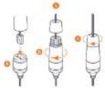
- To use the camera's water proof wiring:
a. Install the LAN cable into 'a'.
b. 'b' will be assembled to 'a' with a 1/4 turn.
c. Thread 'c' tightly to 'b'.Adjust the camera to obtain an optimum angle by loosening the
- Secure the camera to the mounting surface with the provided screws.
- Adjust the camera to obtain an optimum angle by using the camera's three axis

text_image
10mm x 20mm 3.5mm x 40mm ① ② ③ ④ ⑤ ⑥
text_image
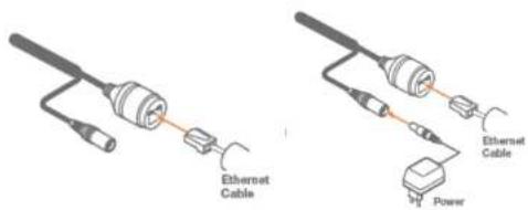
Pan: 0° - 260° Tilt: 0° - 60°4 Cabling
- NETWORK CONNECTIONS - If you are using a PoE Switch, connect the camera using an Ethernet cable for both data and power.
- NETWORK CONNECTIONS - If you are using a non-PoE switch, connect the camera to the switch using an Ethernet cable for data transmission and use a power adapter to power the camera.
text_image
Ethernet Cable Power Ethernet CableUse the diagram below to connect all external devices to the camera:

flowchart
graph TD
    A["Monitor"] --> B["Network Cable"]
    B --> C["DC12V"]
    C --> D["Monitor"]
    D --> E["Display"]
* 1 It is recommended to install the water-proof cap for network cable connection.
* 2 If the PoE network switch is used to connect the camera that supports PoE power supply. DC12V power supply is not required.
5 Live View
To log In to the camera, open an Internet Explorer page and input the camera's IP address. If you are connecting to the camera for the first time, be sure to download the ActiveX control. After downloading, a login window will pop up as shown below.

text_image
DW DIGITAL WATCHDOG Complete Service Solution Name: admin Password: ****** Stream Type: 250x1440 Mbps Language: English Remember me LightInput the username and password to log in.

The default username is "admin"; the default password is "admin".
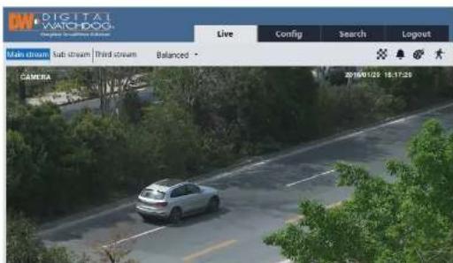
After you log in, you will see the following window.
text_image
DIGITAL WATCHDOG Main stream Sub stream Third stream Balanced CAMERA Live Config Search Logout 2016/01/29 18:17:25The following table is the instructions of the icons on the live view interface.
| Icon Description Icon Description | ||
| Original size SD card recording indicator | ||
| Fit correct scale Color abnormal indicator | ||
| Auto (fill the window) Abnormal clarity indicator | ||
| Full screen Scene change indicator | ||
| Start/stop live view Line crossing indicator | ||
| Start/stop two-way audio Crowdsensity indicator | ||
| Enable/disable audio People counting indicator | ||
| Snapshot Object removal indicator | ||
| Start/stop local recording | ||
| Zoom in People intrusion indicator |
| Icon Description Icon Description | ||
| Zoom out Sensor alarm indicator() | ||
| PTZ control Motion alarm indicator() | ||
| AZ control (only available for the model with motorized zoom lens) |
- Those smart alarm indicators will flash only when the camera supports those functions and the corresponding events are enabled.
- In full screen mode, double click on the mouse to exit or press the ESC key on the keyboard.
Click AZ control button to show AZ control panel. The descriptions of the control panel are as follows:
| Icon | Description | Icon | Description |
The camera can be installed in a compatible external PTZ enclosure through RS485.
Click the PTZ icon to reveal the PTZ control panel. (This function is only available for
the model with RS485 interface).
The descriptions of the control panel are as follows:
| Icon Description Icon Description | |||
| Move upper left direction Move upper right direction | |||
| Move up Stop movement | |||
| Move left Move right | |||
| Move lower left direction Move lower right direction | |||
| Move down Speed adjustment | |||
| Zoom out Zoom in | |||
| Focus - Focus * | |||
| Iris - Iris + | |||
| Auto scan Wiper | |||
| Light | Radom scan | ||
| Group scan Preset |
Select preset and click to call the preset. Select and set the preset and then click
to save the position of the preset. Select the set preset and click to delete it.
6 Camera Configuration
In the DW web client, choose "Config" to go to the configuration interface. Note: Wherever applicable, click the "Save" button to save the settings.
6.1 System Configuration
6.1.1 Basic Information
In the "Basic Information" interface, the system information of the device is listed.
| Device Name | IPC |
| Product Model | xxxx |
| Brand | Customer |
| Software Version | 4.2.10(14734) |
| Software Build Date | 2017-12-12 |
| Kernel Version | 20171115 |
| Hardware Version | L3-1314205 |
| Orvif Version | 16.12(#2) |
| OCX Version | 2.0.2.7 |
| MAC | 00:18:ae:58:23:eb |
Some versions may support device ID and QR code. Having enabled P2P (see Network Configuration-P2P), the network camera can be quickly added to mobile surveillance client, by scanning the QR code or entering device ID.
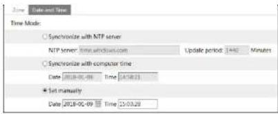
6.1.2 Date and Time
Go to Config→System→Date and Time. Please refer to the following interface.
| Name | Data and Time | |||
| Time Zone: | CAST+08 (Beijing, Hong Kong, Shenzhen, Taipei) | |||
| □ Auto DST | ||||
| Manual DST | ||||
| Start Time | Hour | 1 Hour | 2 Hour | Hour |
| End Time | Hour | 1 Hour | 2 Hour | Hour |
text_image
Time Mode Synchronize with NTP server NTP server Time: 24/18/2003 Update period: 1440 Minutes Synchronize with computer time Date: 2018-01-09 Time: 24/18/21 Set manually Date: 2018-01-09 Time: 25/03/286.1.3 Local Config
Go to Config→System→Local Config to set up the storage path of captured pictures and recorded videos on the local PC. There is also an option to enable or disable the bitrate display in the recorded files.
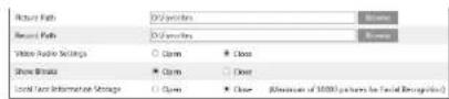
If the camera support face detection, local face information storage can be set up here. (Face detection function is only available for some specified versions).
6.1.4 Storage
This function is only available for the model with SD slot.
Go to Config→System→Storage to go to the interface as shown below.

text_image
Management Record Snapshot Total picture capacity 14820 MS Picture remaining space 5668 MS Total recording capacity 14784 MS Record remaining space 3 MS Status Normal Snapshot Quota 50 % Video Quota 50 % Changes in the quota ratio need to be formatted before they become effective. OK Normal• SD Card Management
Click the "Format" button to format the SD card. All data will be cleared by clicking this
button.
Click the "Eject" button to stop writing data to SD card. Then the SD card can be ejected
safely
Snapshot Quota: Set the capacity proportion of captured pictures on the SD card.
Video Quota: Set the capacity proportion of record files on the SD card.
- Schedule Recording Settings
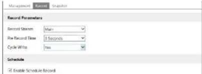
- Go to Config→System→Storage→Record to go to the interface as shown below.
text_image
Management Source Snapshot Record Parameters Record Stream: Main First Record Time: 3 Seconds Cycle White: Two Schedule ✓ Enable Schedule Record- Sel record stream, pre-record time, cycle writing.
Pre Record Time: Set the time to record before the actual recording begins.
- Set schedule recording. Check "Enable Schedule Record" and set the schedule.

text_image
Week Schedule Sun: 01:00-24:00 Mon: 01:00-24:00 Tue: 23:00-27:00 Wed: 23:00-27:00 Thu: 23:00-27:00 Fri: 23:00-27:00 Sat: 23:00-27:00 Date 07.12 Add Manual Report Manual Report Manual Report Manual Report Manual Report Manual Report Manual ReportWeekly schedule
Set the alarm time from Monday to Sunday for a single week. Each day is divided in
one hour increments. Green means scheduled. Blank means unscheduled. Note that
if a specific time period is not scheduled for motion, the camera will not generate a
motion alarm even if motion is enabled.
"Add": Add the schedule for a special day. Drag the mouse to set the time on the timeline.
"Erase": Delete the schedule. Drag the mouse to erase the time on the timeline.
Manual Input: Click it for a specific day to enter specific start and end times. This adds more granularities (minutes).
Day schedule
Set the alarm time for alarm a special day, such as a holiday.
Note: Holiday schedule takes priority over weekly schedule.
- Snapshot Settings
Go to Config→System→Storage→Snapshot to go to the interface as shown below.

text_image
Management Record Snapshot Snapshot Parameters Image Format JPEG Resolution 2592x1520 Image Quality High Event Trigger Snapshot Interval 1 Second Snapshot Quantity 5 Schedule Enable Timing Snapshot Snapshot Interval 1 SecondSel the format, resolution and quality of the image saved on the SD card and the snapshot interval and quantity and the timing snapshot here.
Timing Snapshot: Enable timing snapshot first and then set the snapshot interval and schedule. The setup steps of schedule are the same as the schedule recording (See Schedule Recording).
6.2 Image Configuration
Image Configuration includes Display, Video/Audio, OSD, Video Mask and ROI Config.
6.2.1 Display Configuration
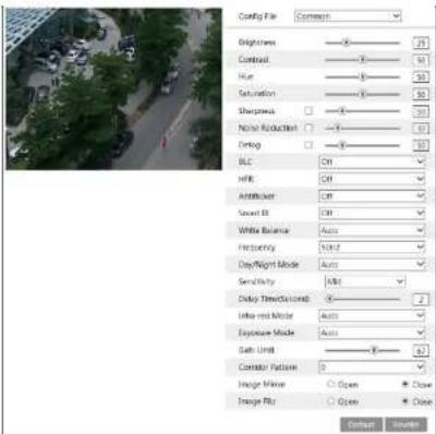
Go to Image→Display interface as shown below. The image's brightness, contrast, hue and saturation and so on for common, day and night mode can be set up separately. The image effect can be quickly seen by switching the configuration file.
text_image
Config File Brightness Contrast Hue Saturation Sharpness Normal Reduction Debug BLC HDR AntihistUser Secret IR White Balance Frequency Day/Night Mode Sensitivity Delay Time(Domain) Infer red Mode Exposure Mode Gate Limit Contactor Pathion Image Value Open Close Image Fill Open Close OK CancelBrightness: Set the brightness level of the camera's image.
Contrast: Set the color difference between the brightest and darkest parts.
Hue: Set the total color degree of the image
Saturation: Set the degree of color purity. The purer the color, the brighter the image
resolution.
Defog: Activating this function and setting an appropriate value as needed in foggy,
dusty, smoggy or rainy environment to get clear images.
Backlight Compensation (BLC):
- Off: disables the backlight compensation function. It is the default mode.
- HWDR
WDR can adjust the camera provide a better image when there are both very bright and very dark areas simultaneously in the field of the view by lowering the brightness of the bright area and increasing the brightness of the dark area. High, middle and low can be selected.
◆ Recording will be stopped for a few seconds while the mode is changing from non-WDR to WDR mode.
- HLC: lowers the brightness of the entire image by suppressing the brightness of the image's bright area and reducing the size of the halo area.
- BLC: If enabled, the auto exposure will activate according to the scene so that the object of the image in the darkest area will be seen clearly.
HFR: If this function is enabled, the system will restart and then the maximum value of the frame rate of the main stream can be set to 60 fps. (This function is not available for motorized zoom cameras).
Anti-flicker:
- Off: disables the anti-flicker function. This is used mostly in outdoor installations.
- 50Hz: reduces flicker in 50Hz lighting conditions.
- 60Hz: reduces flicker in 60Hz lighting conditions
White Balance: Adjust the color temperature according to the environment automatically.
Frequency: 50Hz and 60Hz can be optional.
Day/night Mode: Please choose the mode as needed.
Sensitivity: High, middle and low can be selected for switching back and forth from day to night modes.
Infrared Mode: Choose "ON", "OFF" and "Auto" (This function is not available for the cameras without infrared lights).
Exposure Mode: Choose "Auto" or "Manual". If manual is chosen, the digital shutter speed can be adjusted.
Corridor Pattern: Corridor viewing modes can be used for situations such as long hallways. 0, 90, 180 and 270 are available. The default value is 0. The video resolution should be 1080P or below if this function is used.
Image Mirror: Turn the current video image horizontally.
Image Flip: Turn the current video image vertically.

Set full time schedule for common, day, night mode and specified time schedule for day and night. Choose "Schedule" in the drop-down box of schedule as shown below.

text_image
Current Parameters Schedule Schedule Schedule Time Range 0:00 4:00 8:00 12:00 15:00 30:00 34:00 Day Night SaveDrag "L" icons to set the time of day and night. Blue means day time and blank means night time. If the current mode of camera parameters is set to schedule, the image configuration mode will automatically switch between day and night according to the schedule.
6.2.2 Video / Audio Configuration
Go to Image→Video / Audio interface as shown below. In this interface, set the resolution, frame rate, bitrate type, video quality and so on subject to the actual network condition.

text_image
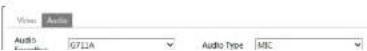
Index Stream Name Revelation Stream Type Stream Quality Value Quality Stream Intense Value Compression Profile Main image StreamName 100 500 300% 100% 50% 100% 50% 100% 50% 100% 50% 100% 50% 100% 50% 100% 50% 100% 50% 100% 50% 100% 50% 100% 50% 100% 50% 100% 50% 100% 50% 100% 50%Click the "Audio" tab to go to the interface as shown below.
Frame rate: The higher the frame rate, the video is smoother.
Bitrate type: CBR and VBR are optional. Bitrate is related to image quality. CBR means that no matter how much change is seen in the video scene, the compression bitrate will be kept constant. VBR means that the compression bitrate will be adjusted according to scene changes. For example, for scenes that do not have much movement, the bitrate will be kept at a lower value. This can help optimize the network width usage.
Bitrate: it can be adjusted when the mode is set to CBR. The higher the bitrate, the better the image quality will be.
Video Quality: It can be adjusted when the mode is set to VBR. The higher the image quality, the more bitrate will be required.
I Frame interval: It determines how many frames are allowed between a "group of pictures". When a new scene begins in a video, until that scene ends, the entire group of frames (or pictures) can be considered as a group of pictures. If there is not much movement in the scene, setting the value higher than the frame rate is fine, potentially resulting in less bandwidth usage. However, if the value is set too high, and there is a high frequency of movement in the video, there is a risk of frame skipping.
Video Compression: H264 and H265 are optional. If H.265 is chosen, make sure the client system is able to decode H.265.
Profile: For H.264. Baseline, main and high profiles are selectable.
Send Snapshot: How many snapshots to generate for an event.
Video encode slice split: If this function is enabled, smooth image can be gotten even though using the low-performance PC.
Watermark: When playing back the local recorded video in the search interface, the watermark can be displayed. To enable it, check the watermark box and enter the watermark text.
Audio Encoding: G711A and G711U are selectable.
Audio Type: MIC and LIN are selectable.
6.2.3 OSD Configuration
Go to Image→OSD interface as shown below.

text_image
Date Format: MATHLETARY Show Timestamp: Device Name: IPC Show Device Name GOLD CURRENT Add One ListSet time stamp, device name, OSD content and picture overlap here. After enabling the corresponding display and entering the content, drag them to change their position. Then Click the "Save" button to save the settings.

text_image
Data Format: MYCD/PYYY Show Timestamp: Device Name: PSC Show Device Name: Picture Overlay: OSD Content2 OSD Content3 OSD Content4 Browse Add One line Add One Line Add One linePicture Overlap Settings:
Check "OSD Content1", choose "Picture Overlay" and click "Browse" to select the overlap picture. Then click "Upload" to upload the overlap picture. The pixel of the image shall not exceed 200*200, or it cannot be uploaded.
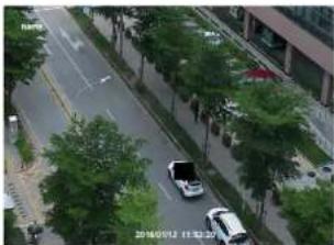
6.2.4 Video Mask
Go to Image→Video Mask interface as shown below. A maximum of 4 zones can be set up.
natural_image
Aerial view of a green truck on a tree-lined road with a white car nearby (no visible text or symbols)To set up video mask:
natural_image
Aerial view of a city street with trees and parked cars, no visible text or symbols.To clear the video mask:
Click the "Clear" button to delete the current video mask area.
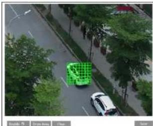
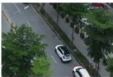
6.2.5 ROI Configuration
Go to Image→ROI Config interface as shown below. An area in the image can be set as a region of interest. This area will have a higher bitrate than the rest of the image, resulting in better image quality for the identified area.

natural_image
Aerial view of two cars driving on a tree-lined road with greenery (no visible text or symbols)- Check "Enable" and then click the "Draw Area" button.
- Drag the mouse to set the ROI area.
- Set the level.
- Click the "Save" button to save the settings.

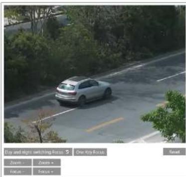
6.2.6 Lens Control
This function is only available for the model with motorized zoom lens. Within this section, zoom and focus can be controlled. If the image is out of focus after a manual adjustment, one key focus can be used to set the focus automatically.
text_image
Key and night switching Focus One Key Focus Zoom : Zoom : Focus : Focus : Reset6.3 PTZ Configuration
This function is only available for the models with RS485 interface. It can be used with a compatible external PTZ enclosure. Go to PTZ→Protocol interface as shown below.

Set the protocol, address and baud rate according to the PTZ.
6.4 Alarm Configuration
6.4.1 Motion Detection
Go to Alarm→Motion Detection to set motion detection alarm.
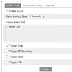
text_image
Alarm Config Enable Alarm Alarm Holding Time 5 Seconds Trigger Alarm Out Alarm Out Trigger Snap Trigger SD Recording Trigger Email Trigger FTP Save- Check "Enable Alarm" check box to activate motion based alarms. If unchecked,
the camera will not send out any signals to trigger motion-based recording to the
NVR or CMS, even if there is motion in the video.
Alarm Out: If selected, this would trigger an external relay output that is connected to
the camera on detecting a motion based alarm
detection (this function is only available for the models with SD card slot).
Trigger Email: If "Trigger Email" and "Attach Picture" are checked (email address must be set first in the Email configuration interface), the captured pictures and triggered event will be sent into those addresses.
Trigger FTP: If "Trigger FTP" and "Attach Picture" are checked, the captured pictures will be sent into FTP server address. Please refer to FTP configuration chapter for more details.
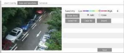
- Set motion detection area and sensitivity. Click the "Area and Sensitivity" tab to go to the interface as shown below.
text_image
Alarm Camera Air and Security Air and Security Saturation Color High 6 Drive Box Add Add Insert Select All Select All InsertMove the "Sensitivity" scroll bar to set the sensitivity. Higher sensitivity value means that motion will be triggered more easily.
Select "Add" and click "Draw". Drag the mouse to draw the motion detection area; Select "Erase" and drag the mouse to clear motion detection area.
After that, click the "Save" to save the settings.
- Set the schedule for motion detection. The schedule setup steps of the motion detection are the same as the schedule recording setup (See Schedule Recording).
6.4.2 Other Alarms
- SD Card Full
- Go to Config→Alarm→Anomaly→SD Card Full.

-
Click "Enable alarm" and set the alarm holding time.
-
Set alarm trigger options. The setup steps are the same as motion detection. Please refer to motion detection chapter for details.
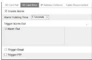
- SD Card Error
When there are some errors in writing SD card, the corresponding alarms will be
triggered.
- Go to Config→Alarm→Anomaly→SD Card Error as shown below.
text_image
SD Card Fail SD Card Error IP Address Collision Cable Disconnected Enable Alarm Alarm Holding Time 5 Seconds Trigger Alarm Out Alarm Out Trigger Email Trigger FTP-
Click "Enable alarm" and set the alarm holding time.
-
Set alarm trigger options. Trigger alarm out, Email and FTP. The setup steps are the same as motion detection. Please refer to motion detection chapter for details. Note: SD card full and SD card error are only available for the models with SD slot.
IP Address Conflict
- Go to Config→Alarm→Anomaly→IP Address Collision as shown below.

text_image
SD Card Full SD Card Error IP Address Collision Cable Disconnected Enable Alarm Alarm Holding Time 3 Seconds Trigger Alarm Out Alarm Out- Click "Enable alarm" and set the alarm holding time.
2 Trigger alarm out. When the ID address of the camera is in conflict with the ID
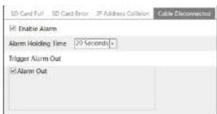
text_image
SD Card Full SD Card Error IP Address Collision Cable Disconnect Enable Alarm Alarm Holding Time 20 Seconds Trigger Alarm Out Alarm Out- Click "Enable alarm" and set the alarm holding time.
- Trigger alarm out. When the camera is disconnected, the system will trigger the alarm out.
6.4.3 Alarm In
This function is only available for some models. To set sensor alarm (alarm in):
Go to Config→Alarm→Alarm In interface as shown below.
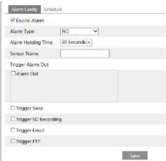
text_image
Alarm Config Schedule Enable Alarm Alarm Type NO Alarm Holding Time 30 Seconds Sensor Name: Trigger Alarm Out Alarm Out Trigger Snap Trigger SD Recording Trigger Email Trigger FTP Save- Click "Enable alarm" and set the alarm type, alarm holding time and sensor name.
- Set alarm trigger options. The setup steps are the same as motion detection.
Please notify the online detection check for details.
6.4.4 Alarm Out
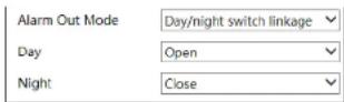
This function is only available for some models. Go to Config→Alarm→Alarm Out.

Alarm Out Mode: Alarm linkage, manual operation, day/night switch linkage and schedule are optional.
Alarm Linkage: Having selected this mode, select alarm out name and alarm holding time at the "Alarm Holding Time" pull down list box.
Manual Operation: Having selected this mode, click "Open" to trigger the alarm out immediately; click "Close" to stop alarm.

Day/Night Switch Linkage: Having selected this mode, choose to open or close day/night switch linkage.
Schedule: Click "Add" and drag the mouse on the timeline to set the schedule of alarm out; click "Erase" and drag the mouse on the timeline to erase the set time schedule. After this schedule is saved, the alarm out will be triggered in the specified time.

6.4.5 Alarm Server

6.5 Video Analytics Configuration (Optional)
(Only some specified versions support the following functions).
For more accuracy, here are some recommendations for installation.
- Cameras should be installed on stable surfaces, as vibrations can affect the accuracy of detection.
- Avoid pointing the camera at the reflective surfaces (like shiny floors, mirrors, glass, lake surfaces and so on).
- Avoid places that are narrow or have too much shadowing.
- Avoid scenario where the object's color is similar to the background color.
- At any time of day or night, please make sure the image of the camera is clear and with adequate and even light, avoiding overexposure or too much darkness on both sides.
6.5.1 Object Removal
The alarm will be triggered when the objects removed from or left at the pre-defined area. This function can be used in such scenarios like object security, debris flow, illegal parking detection, illegal pasting, illegal doodle, etc.
To set object removal:
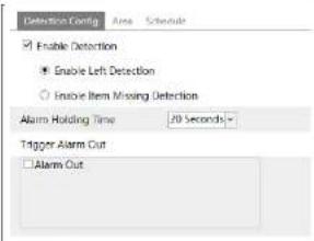
Go to Config→Event→Object Removal interface as shown below.
text_image
Detection Config Enable Detection Enable Left Detection Enable Item Missing Detection Alarm Holding Time 70 Seconds Trigger Alarm Out Alarm Out- Enable object removal detection and then select the detection type.
Enable Left Detection: Alarms will be triggered if there are items left in the predefined area.
Enable Item Missing Detection: Alarms will be triggered if there are items missing in the pre-defined area. - Set the alarm holding time and alarm trigger options. The setup steps are the same as motion detection. Please refer to motion detection chapter for details.
- Click "Save" button to save the settings.
- Set the alarm area of the object removal detection. Click the "Area" tab to go to the interface as shown below.

text_image
Centroidion Setup Name Schedule Name Area 1 Area Name: XXX Draw Area Clear SaveSet the alarm area number and then enter the desired alarm area name. Up to 4 alarm areas can be added. Click the "Draw Area" button and then click around the area where you want to set as the alarm area in the image (the alarm area should be a closed area). Click the "Stop Draw" button to stop drawing. Click the "Clear" button to delete the alarm area. Click the "Save" button to save the settings,
- Set the schedule of the object removal detection. The setup steps of the schedule are the same as the schedule recording setup (See Schedule Recording).
※ The configuration requirements of camera and surrounding areas
- The range of the detection object should occupy from 1/50 to 1/3 of the entire image.
- The detection time of objects in the camera shall be from 3 to 5 seconds.
- The defined area cannot be covered frequently and continuously (like people and traffic flow).
-
It is necessary for object removal detection that the drawn frame must be very close
-
Try not to enable object removal detection if there are complex and dynamic environments in the scene.
- Adequate light and clear scenery are very important to object removal detection.
- Please contact us for more detailed application scenarios.
Here we take some improper application scenarios for instance.

natural_image
Exterior view of a modern office building with surrounding greenery and parking lot (no visible text or signage)There are so many trees near the road and cars running on the road, which make the scene too complex to detect the removal objects.
6.5.2 Exception
This function can detect changes in the surveillance environment affected by the external factors.
To set exception detection:
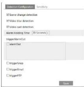
Go to Config→Event→Exception interface as shown below.
text_image
Detection Configuration Sensitivity Scene change detection Video shot detection Video cast detection Alarm Holding Time 20 Seconds+ trigger/AlarmOut alarmOut triggerSnap triggerEmail triggerFTP SaveVideo Cast Detection: Alarms will be triggered if the video becomes obscured.
- Set the alarm holding time and alarm trigger options. The setup steps are the
same as motion detection. Please refer to motion detection chapter for details. - Click "Save" button to save the settings.
- Set the sensitivity of the exception detection. Click "Sensitivity" tab to go to the interface as shown below.

Drag the slider to set the sensitivity value or directly enter the sensitivity value in the textbox. Click "Save" button to save the settings.
The sensitivity value of Scene Change Detection: The higher the value is, the more sensitive the system responds to the amplitude of the scene change.
The sensitivity value of Video Blur Detection: The higher the value is, the more sensitive the system responds to the blurriness of the image.
The sensitivity value of Video Cast Detection: The higher the value is, the more sensitive the system responds to the obscuring of the image.
※ The requirements of camera and surrounding area
- Auto-focusing function should not been enabled for exception detection.
- Try not to enable exception detection when light changes greatly in the scene.
- Please contact us for more detailed application scenarios.
6.5.3 Line Crossing
Line Crossing: Alarms will be triggered if someone or something crosses the predefined alarm lines. It can replace the electronic fence, warning line of flood
prevention, etc.
Go to Config→Event→Line Crossing interface as shown below.

text_image
Detection Config Enable Alarm Alarm Holding Time 20 Seconds Trigger Alarm Out Alarm Out Trigger Snap Trigger Email Trigger FTP Solder- Enable line crossing alarm and set the alarm holding time.
- Set alarm trigger options. The setup steps are the same as motion detection.
Please refer to motion detection chapter for details. - Click "Save" button to save the settings.
- Set area and sensitivity of the line crossing alarm. Click the "Area and Sensitivity" tab to go to the interface as shown below.
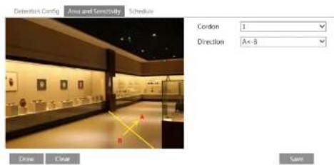
text_image
Dentarium Config Area and Sensitivity Schedule Cordon 1 Direction Ax-B Drawn Draw SaveSet the cordon number and direction. Up to 4 lines can be added. Multiple lines cannot be added simultaneously.
Direction: A<->B, A->B and A<-B optional. This indicates the direction of the intruder
A<-B: The alarm will be triggered when the intruder crosses over the alarm line from B to A.
Click the "Draw" button and then drag the mouse to draw a cordon in the image. Click the "Stop" button to stop drawing. Click the "Clear" button to delete the cordons. Click the "Save" button to save the settings.
- Set the schedule of the line crossing alarm. The setup steps of the schedule are the same as the schedule recording setup (See Schedule Recording).
※ Configuration of camera and surrounding area
-
Auto-focusing function should not be enabled for line crossing detection.
-
Avoid the scenes with many trees or the scenes with various light changes (like many flashing headlights). The ambient brightness of the scenes shouldn't be too low.
-
Cameras should be mounted at a height of 2.8 meters or above.
-
Keep the mounting angle of the camera at about 45°.
-
The detected objects should not be less than 1% of the entire image and the largest sizes of the detected objects should not be more than 1/8 of the entire image.
-
Make sure cameras can view objects for at least 2 seconds in the detected area for accurate detection.
-
Adequate light and clear scenery are crucial for line crossing detection.
-
Please contact us for more detailed application scenarios.
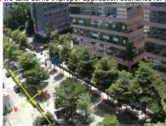
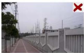
Here we take some improper application scenarios for instance.
natural_image
Exterior view of a modern office building with surrounding greenery and a paved walkway (no visible text or signage)There are so many trees near the road and cars running on the road, which make the scene too complex to detect the crossing objects.
natural_image
Exterior view of a modern building with flagpoles and a decorative tree in the foreground (no signage)The ground is covered with vegetation; at the right of the fence is a gym where people pass by frequently. The above mentioned environment is too complex to detect the crossing objects.
6.5.4 Intrusion
Intrusion: Alarms will be triggered if someone or something intrudes into the predefined areas. This function can be applicable to important supervision places, danger areas and prohibited areas, like military administrative zones, house breaking, scenic high danger areas, no man's areas, etc. Go to Config→Event→Intrusion interface as shown below.
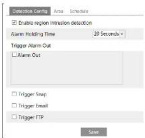
text_image
Detection Config Enable region intrusion detection Alarm Holding Time 20 Seconds Trigger Alarm Out Alarm Out Trigger Snap Trigger Email Trigger FTP Save- Enable region intrusion detection alarm and set the alarm holding time.
- Set alarm trigger options. The setup steps are the same as motion detection. Please refer to motion detection chapter for details.
- Click the "Save" button to save the settings.

text_image
Detection Cavity Area Spectrum Alarm Area 1 Crow Area Clear SaveSet the alarm area number on the right side. Up to 4 alarm areas can be added.
Click the "Draw Area" button and then click around the area where you want to set as
the alarm area in the image on the left side (the alarm area should be a closed area).
Click the "Stop Draw" button to stop drawing. Click the "Clear" button to delete the alarm area. Click the "Save" button to save the settings.
- Set the schedule of the intrusion detection. The setup steps of the schedule are the same as schedule recording setup (See Schedule Recording).
※ Configuration requirements of camera and surrounding area
-
Auto-focusing function should not be enabled for intrusion detection.
-
Avoid the scenes with many trees or the scenes with various light changes (like many flashing headlights). The ambient brightness of the scenes shouldn't be too low.
-
Cameras should be mounted at a height of 2.8 meters or above.
-
Keep the mounting angle of the camera at about 45^ .
-
The detected objects should not be less than 1% of the entire image and the largest sizes of the detected objects should not be more than 1/8 of the entire image.
-
Make sure cameras can view objects for at least 2 seconds in the detected area for accurate detection.
-
Adequate light and clear scenery are crucial to line crossing detection.
-
Please contact us for more detailed application scenarios.
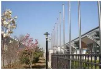
Here we take some improper application scenarios for instance.

natural_image
Exterior view of a fence with green trees and a distant structure (no signage or text visible)The camera's angle of depression is not wide enough; there are so many trees in the scene. The above mentioned environment is too complex to detect the intrusion.
natural_image
Exterior view of a railway track with overhead power lines and a fence, no visible text or symbolsThe camera's angle of depression is not wide enough; the street lamps at night lead to light interference; the swaying trees in a windy day lead to random interference. All the above mentioned factors make the scene improper for intrusion detection.
6.5.5 Crowd Density Detection
This function detects the density of the walking people in a specified area (square, supermarket) and evaluates the level. Go to Config→Event→Crowd Density as shown below.

text_image
Alarm Config Area Schedule Enable Refresh Frequency 1 Seconds Density Alarm Threshold 21% Alarm Holding Time 20 Seconds Trigger Alarm Out Alarm Out Trigger Snap Trigger SD Recording Trigger Email Trigger FTP- Enable the crowd density detection.
- Set "Refresh Frequency", "Density Alarm Threshold" and "Alarm Holding Time". Refresh Frequency: It refers to the period of a detection result report.
Density Alarm Threshold: The camera will trigger an alarm once the percentage of the crowd density in a specified area exceeds the pre-defined threshold value. - Set alarm trigger options. The setup steps are the same as motion detection. Please refer to motion detection chapter for details.
- Set an alarm area for the crowd density detection. Click the "Area" tab as shown below.
Click "Draw Area" and drag the mouse to draw a rectangle area. Drag the boundary of the rectangle to modify its size and move the rectangle to change its position. Click "Stop Draw" to stop drawing the area. Click "Clear" to clear the area.
text_image
Alarms Config Area Schedule Draw Area Clear- Set the schedule of the crowd density detection. The setup steps of the schedule are the same as schedule recording setup (See Schedule Recording).
※Configuration of camera and surrounding area
- The lens direction of the camera shall be the same as people flow, allowed a little bit incline. The direction of the people flow shall be less than 45^ from the horizontal. It is recommended that the angle between the lens of the camera and the floor shall be between 30^ and 60^ .
- The size of a single person of the people flow shall take up between 1% and 5% of the entire image and the height of the figure occupies from 1/5 to 1/2 of the entire image.
- This function is inapplicable to the scene where there are many moving objects except human shape, like moving car.
- Abundant trees and billboards are not allowed in the detected area.
6.5.6 People Intrusion
This function is specially designed for the use of indoor scenes. To prevent someone from intruding indoor to endanger the family security, alarms will be triggered if someone enters into the detection area in 3\~5s. The setup steps are as follows.
- Go to Config→Event→People Intrusion. Please refer to the following picture.
- Enable the people intrusion detection.
- Set "Alarm Sensitivity" and "Alarm Holding Time"
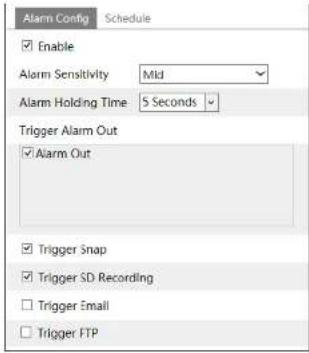
text_image
Alarm Config Schedule Enable Alarm Sensitivity Mid Alarm Holding Time 5 Seconds Trigger Alarm Out Alarm Out Trigger Snap Trigger SD Recording Trigger Email Trigger FTP※ Configuration requirements of camera and surrounding area
- The detection area should have stable and adequate light.
- In order to detect the moving people or objects in the whole detection area, camera shall be mounted at a height of 1-3 meter(s).
- To make sure the camera shoots all the indoor scenes, the camera lens should be to the detected direction and the camera had better be installed in the corner.
- The proportion of the detection people occupies from 1/5 to 1/2 of the whole picture.
- The false alarm will be triggered if the indoor scenes have cluttered and frequently changing lights.
- With family members in the house, it is no need to enable this function.
- This function is inapplicable to outdoors.
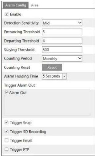
6.5.7 People Counting
This function is to count the quantities of the bidirectional people flow in the detected areas by detecting, tracking and counting the head shape of the people. The counting data includes the number of entering people, exiting people and remaining people. The setup steps are as follows.
- Go to Config→Event→People Counting. Please refer to the following picture.
Any pre-defined threshold value surpassed (the default value is 500; the maximum value is 655350), the alarm of the camera will be triggered.
When people pass the detected area along with the flow, it will take 1–5 seconds to complete the detection of people counting according to different scenes.
- Set alarm trigger options. The setup steps are the same as motion detection. Please refer to motion detection chapter for details.
text_image
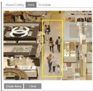
Alarm Config Area Enable Detection Sensitivity Mid Entrancing Threshold 5 Departing Threshold 4 Staying Threshold 500 Counting Period Monthly Counting Reset Reset Alarm Holding Time 5 Seconds Trigger Alarm Out Alarm Out Trigger Snap Trigger SD Recording Trigger Email Trigger FTP- Set the area of the people counting. Click the "Area" tab to go to the area setting interface.

text_image
Alarm Config Area Draw Area CloseClick "Draw Area" and drag the mouse to draw a rectangle area. Drag the four boundary lines of the rectangle to modify its size and move the rectangle to change its position. Click "Stop Draw" to stop drawing the area. Click "Clear" to clear the area. Click and drag the arrow or the other end of the arrow line to change the people entrancing direction.
The detected area must be larger than the width of the main hallway of the people flow (hereinafter referred to as "hallway"), reserved a certain distance from the edge of the picture (the width of the undetected areas shall occupy 4%\~10% of the whole picture).
The direction of detection shall be in conformity to the direction of the hallway as shown in the picture above. The area drawn yellow box is the detected area. The head size of the figure (width or height) shall account for 1/5 - 1/2 of the drawn detection area.
The direction along with the red arrow is entrance direction and the opposite direction of the red arrow is exiting/departing direction.
After the people counting detection is successfully set up, the counting results will be seen by clicking "Live" tab. Please refer to the following picture.

text_image
CIC 图 1- The background color (like floor color) of the installation shall be light color.
- The lens of the camera shall be adjusted straight down, allowed a little bit incline but the whole head must be captured.
- The installation height of the camera depends on the actual focal length of the lens. The hallway shall take up over a half of the width of the entire image and the head of the people shall be about 1/5 of the height of the entire image. Reserving certain space on both sides makes the hallway lie in the center of the entire image.
The recommending height of installation as shown below:
| Lens | Mounting height |
| 2.8mm | 2.6 ~ 3.2m |
| 3.3mm | 3.0 ~ 4.0m |
| 3.6mm | 3.3 ~ 5.0m |
- More than two directions of people flow are not allowed in the scenes.
- Various changeable lights will disturb the people counting and the darker scenes will reduce the accuracy of counting.
- If the camera is installed in a higher place, the head feature will not be traced completely due to too little proportion of the head of the figure in the picture.
- If the figure is moving at a high speed (passing the detected area within 2 seconds), it may result in detection failure. If the figure is moving at a low speed, staying more than 15 seconds in the detected area, the camera will give up tracing.
- If the cloth color of the people is similar with the color of the background, it may cause detection failure.
- More headwears probably conceal the head features, which will lead to detection failure.
6.6 Network Configuration
6.6.1 TCP/IP
Go to Config→Network→TCP/IP interface as shown below. There are two ways for network connection.

text_image
IPv4 IPv6 PPPCE Config IP Change Notification Config Obtain an IP address automatically Use the following IP address IP Address 192.168.226.201 Test Subnet Mask 255.255.255.0 Gateway 192.108.226.1 Preferred DNS Server 210.21.196.6 Alternate DNS Server 8.8.8.8Use IP address (take IPv4 for example)-There are two options for IP setup: obtain an IP address automatically by DHCP and use the following IP address. Please choose one of the options as needed.
Test: Test the effectiveness of the IP address by clicking this button.
Use PPPoE-Click the "PPPoE Config" tab to go to the interface as shown below. Enable PPPoE and then enter the user name and password from your ISP.

text_image
P+4 Pvs PPFE Config IP Change Notification Config Enable User Name xxxxxxx Password ••••••• SalarEither method of network connection can be used. If PPPoE is used to connect internet, the camera will get a dynamic WAN IP address. This IP address will change frequently. To be notified, the IP change notification function can be used.
Click "IP Change Notification Config" to go to the interface as shown below.
ID-val ID-AL BDO-F-Crude In Figure Modification Guide
Trigger Email: when the IP address of the device is changed, the new IP address will be sent to the email address that has been set up.
Trigger FTP: when the IP address of the device is changed, the new IP address will be sent to FTP server that has been set up.
6.6.2 Port
Go to Config→Network→Port interface as shown below. HTTP port, Data port and RTSP port can be set.
| HTTP Port | 80 |
| HTTPS Port | 443 |
| Data Port | 9008 |
| RTSP Port | 554 |
HTTP Port: The default HTTP port is 80. It can be changed to any port which is not occupied.
HTTPS Port: The default HTTPS port is 443. It can be changed to any port which is not occupied.
Data Port: The default data port is 9008. Please change it as necessary.
RTSP Port: The default port is 554. Please change it as necessary.
6.6.3 Server Configuration
This function is mainly used for connecting network video management system.
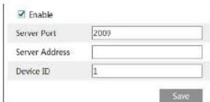
text_image
Enable Server Port 2009 Server Address Device ID 1 Save-
Check "Enable".
-
Check the IP address and port of the transfer media server in the ECMS/NVMS.
Then enable the auto report in the EOMS/M/MS when adding a new device. Next
6.6.4 DDNS
If the camera is set up with a DHCP connection, DDNS should be set for the internet.
- Go to Config→Network→DDNS.
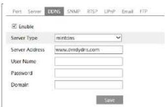
text_image
Port Server DNS SNMP RTSP LPhP Email FTP Enable Server Type mintrns Server Address www.dvrdydns.com User Name : Password : Domain : Save- Apply for a domain name. Take www.dvrdyndns.com for example.
Enter www.dvrdydns.com in the IE address bar to visit its website. Then Click the "Registration" button.
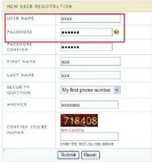
text_image
NEW USER REGISTRATION USER NAME xxxx PASSWORD **** PASSWORD CONFIGUR **** FIRST NAME xxx LAST NAME xxx SECURITY QUESTION My first phone number ANSWER xxxxxx CONFIR A YOUR RE HUMAN 718408 Enter the text you see above Submit ResetCavista della
After the domain name is successfully applied for, the domain name will be listed as below.

- Enter the username, password, domain you apply for in the DDNS configuration
interface. - Click the "Save" button to save the settings.
6.6.5 SNMP
To get camera status, parameters and alarm information and remotely manage the camera, the SNMP function can be used. Before using SNMP, please install an SNMP management tool and set the parameters of the SNMP, such as SNMP port, trap address.
- Go to Config→Network→SNMP.
- Check the corresponding version checkbox (Enable SNMPv1, Enable SNMPv2, Enable SNMPv3) according to the version of the SNMP software that will be used.
- Set the values for "Read SNMP Community", "Write SNMP Community", "Trap Address", "Trap Port" and so on. Please make sure the settings are the same as that of the SNMP software.
Note: Please use the different version in accordance with the security level you required. The higher the version is, the higher the level of the security is.

text_image
SNMP v3/v2 Enable SNMPv1 Enable SNMPv2 Read SNMP Community Write SNMP Community Trap Address Trap Port 0 Trap community SNMP v3 Enable SNMPv3 Read User Name Security Level auth.pty Authentication Algorithm MDS SHA Authentication Password Private Key Algorithm DES AES Private Key Algorithm Write User Name Security Level auth.pty Authentication Algorithm MDS SHA Authentication Password Private Key Algorithm DES AES Private Key Algorithm Other Settings SNMP Port 06.6.6 802.1x
IEEE802.X which is an access control protocol manages the device in connection with the local network by authentication. The setup steps are as follows:
| Enable | |
| Protocol Type | FAP_MDS |
| FAPCS Version | 1 |
To use this function, the camera shall be connected to a switch supporting 802.1x protocol. The switch can be reckoned as an authentication system to identify the device in a local network. If the camera connected to the network interface of the switch has passed the authentication of the switch, it can be accessed via the local network.
Protocol type and EAPOL version: Please use the default settings.
User name and password: The user name and password must be the same with the user name and password applied for and registered in the authentication server.
The structure of 802.1x

flowchart
graph LR
    IPC --> LAN/WLAN
    LAN/WLAN --> Switch
    Switch --> Authentication Server
① The network camera initiates the authentication of 802.1x protocol via web client and then the authentication is received by the switch supporting 802.1x protocol.
② The switch provides the camera with a physical or logic local network interface and verifies the camera.
⑤ Authentication server provides the entity of authentication service for the switch, stored the relative information of web client, realizing the authentication of web client. Please refer to the user manual of the connected switch for more details.
6.6.7 RTSP
Go to Config→Network→RTSP.
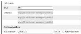
text_image
IRI Enable Port: 554 Address: http://bit or domain name/port/ulife/ http://bit or domain name/port/ulife/ multistead address Main stream: 260.0.0.0 50554 Automatic startSelect "Enable" to enable the RTSP function.
Port: Access port of the streaming media. The default number is 554.
RTSP Address: The RTSP address (unicast) format that can be used to play the stream in a media player.
Multicast Address
Main stream: The address format is
"rtsp://IP address: rtsp port/profile1?transportmode=mcast".
Sub stream: The address format is
"rlsp://IP address: rlsp port/profile2?transportmode=mcast".
Third stream: The address format is
"rtsp://IP address: rtsp port/profile3?transportmode=mcast".
Audio: Having entered the main/sub stream in a VLC player, the video and audio will play automatically.
If "Allow anonymous login..." is checked, there is no need to enter the username and password to view the video.
If "auto start" is enabled, the multicast received data should be added into a VLC player to play the video.
Note:1. This camera support local play through a VLC player. Enter the RTSP address (unicast or multicast, eg. rtsp://192.168.226.201:554/profile1?transportmode=mcast) in a VLC player to realize the simultaneous play with the web client.
-
The IP address mentioned above cannot be the address of IPv6.
-
Avoid the use of the same multicast address in the same local network.
-
When playing the video through the multicast streams in a VLC player, please pay attention to the mode of the VLC player. If it is set to TCP mode, the video cannot be played.
-
If the coding format of the video of the main stream is MJPEG, the video may be disordered at some resolutions.
6.6.8 UPNP
If this function is enabled, the camera can be quickly accessed through the LAN.
Go to Config→Network→UPnP. Enable UPNP and then enter UPnP name.
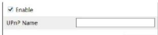
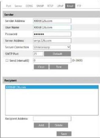
text_image
Port Server CDNS SNMP RTSP URLP Email FTP Sender Sender Address XXX@126.com User Name XXX@126.com Password ****** Server Address unip.126.com Secure Connection Unnecessary SMTP Port 25 Default Send Interval(S) 0 (0-3600) Clear Test Recipient XXXX@126.com Recipient Address Add Delete SaveSender Address: sender's e-mail address.
User name and password: sender's user name and password.
Server Address: The SMTP IP address or host name.
Select the secure connection type at the "Secure Connection" pull-down list according to what's required.
SMTP Port: The SMTP port.
Send Interval(S): The time interval of sending email. For example, if it is set to 60 seconds and multiple motion detection alarms are triggered within 60 seconds, they will be considered as only one alarm event and only one email will be sent. If one motion alarm event is triggered and then another motion detection alarm event is triggered after 60 seconds, two emails will be sent. When different alarms are triggered at the same time, multiple emails will be sent separately.
6.6.10 FTP
After an FTP server is set up, captured pictures from events will be uploaded to the
FTP server.
Go to Config→Network→FTP.

text_image
Port Server DONS SWAP KTFE UMP Email FTP Server Name Server Address Port User Name Upload Path Add FTP Server Name Server Address Upload Path Examples/DirFolder Port 25 User Name Password Anonymous OK Cancel Add Remove Add SaveServer Name: The name of the FTP server.
Server Address: The IP address or domain name of the FTP.
Upload Path: The directory where files will be uploaded to.
Port: The port of the FTP server.
Use Name and Password: The username and password that are used to login to the
FTP server.
6.6.11 HTTPS
HTTPS provides authentication of the web site and protects user privacy.
Go to Config Config→Network→HTTPS as shown below.
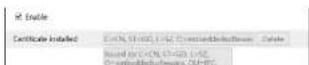
There is a certificate installed by default as shown above. Enable this function and save it. Then the camera can be accessed by entering https://IP; https port via the web browser (eg. https://192.168.226.201:443).
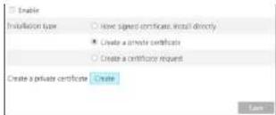
A private certificate can be created if users don't want to use the default one. Click "Delete" to cancel the default certificate. Then the following interface will be displayed.
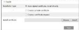
* If there is a signed certificate, click "Browse" to select it and then click "Install" to install it.
* Click "Create a private certificate" to enter the following creation interface.
text_image
Enable Installation type Have signed certificates install directly Create a private certificate Create a certificate request Create a private certificate Create SaveClick the "Create" button to create a private certificate. Enter the country (only two letters available), domain (camera's IP address/domain), validity date, password, province/state, region and so on. Then click "OK" to save the settings.
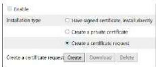
* Click "Create a certificate request" to enter the following interface.
text_image
Enable Installation type Have signed certificate, install directly Create a private certificate Create a certificate request Create a certificate request Create Download DeleteClick "Create" to create the certificate request. Then download the certificate request and submit it to the trusted certificate authority for signature. After receiving the signed certificate, issued the certificate to the device
6.6.12 P2P (Optional)
If this function is enabled, the network camera can be quickly accessed by adding the device ID in mobile surveillance client or CMS/NVMS client via WAN. Enable this function by going to Config→Network→P2P interface.

6.6.13 QoS
QoS (Quality of Service) function is used to provide different quality of services for different network applications. With the deficient bandwidth, the router or switch will sort the data streams and transfer them according to their priority to solve the network delay and network congestion by using this function.
Go to Config→Network→QoS.
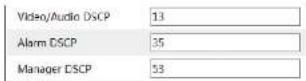
Video/Audio DSCP: The range is from 0 to 63.
Alarm DSCP: The range is from 0 to 63.
Manager DSCP: The range is from 0 to 63.
Generally speaking, the larger the number is, the higher the priority
is
6.7 Security Configuration
6.7.1 User Configuration
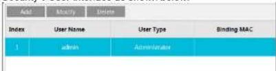
Go to Config→Security→User interface as shown below.
text_image
Add Modify Delete Index User Name User Type Binding MAC 1 admin AdministratorAdd user:
- Click the "Add" button to pop up the following textbox.
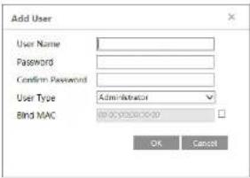
text_image
Add User User Name: Password: Confirm Password: User Type: Administrator Bind MAC OK Cancel-
Enter user name in "User Name" textbox.
-
Enter letters or numbers in "Password" and "Confirm Password" textbox.
-
Choose the use type. Administrator has all permissions. Normal user can only view the live video. Advanced user has the same permissions as an Administrator except for; user, backup settings, factory reset, and upgrading the firmware.
-
Enter the MAC address of the PC in "Bind MAC" textbox.
If this option is enabled, only the PC with the specified MAC address can access the camera for that user.
- Click the "OK" button and then the newly added user will be displayed in the user list.
Modify user:
-
Select a user to modify password and MAC address if necessary in the user configuration list box.
-
The "Edit user" dialog box pops up by clicking the "Modify" button.
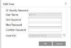
text_image
Edit User Modify Password User Name: admin Old Password: New Password: Confirm Password: Find MAC: OK Cancel- Click the "OK" button to save the settings.
Note: To change the access level of a user, the user must be deleted and added again
with the new access level.
Delete user:
-
Select the user to be deleted in the user configuration list box.
-
Click the "Delete" button to delete the user.
Note: The default administrator account cannot be deleted.
6.7.2 Online User
Go to Config→Security→Online User to view the user who is viewing the live video.
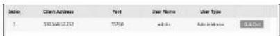
An administrator user can kick out all the other users (including other administrators).
6.7.3 Block and Allow Lists
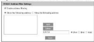
Go to Config→Security→Block and Allow Lists as shown below.
text_image
INMAC Origin Filter Settings If Connection address is moving: - Close the following address: □ Follow the following address App Link 0.5.0 + Pin □ Web □ MAC LimitThe setup steps are as follows:
Check the "Enable address filtering" check box.
Select "Block/Allow the following address", IPv4/IPv6/MAC and then enter IP address
or MAC address in the address box and click the "Add" button.
6.7.4 Security Management
Go to Config→Security→Security Management as shown below.

function can be enabled here. If this function is enabled, login failure after trying six times will make the login interface locked. The camera can be logged in again after a half hour or after the camera reboots.
For some specified versions, anonymous login with a private protocol can be enabled here. If this function is enabled, enter http://host:port/Anonymous/[2/3] (eg. http://192.168.226.201;80/Anonymous/1) via web browser to access the camera. 1 indicates main stream; 2 indicates sub stream; 3 indicates third stream. Only video can be viewed by this means and no other operations can be done. If no such function, please skip the instruction.
6.8 Maintenance Configuration
6.8.1 Backup and Restore
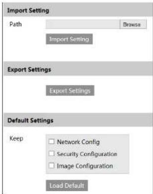
Go to Config→Maintenance→Backup & Restore.
text_image
Import Setting Path Browse Import Setting Export Settings Export Settings Default Settings Keep Network Config Security Configuration Image Configuration Load Default- Import & Export Settings
Configuration settings of the camera can be exported from a camera into another camera.
settings.
6.8.2 Reboot
Go to Config→Maintenance→Reboot.
Click the "Reboot" button to reboot the device.
Timed Reboot Setting:
If necessary, the camera can be set up to reboot on a time interval. Enable "Time
Settings", set the date and time and then click the "Save" button to save the settings.
6.8.3 Upgrade
Go to Config→Maintenance→Upgrade. In this interface, the camera firmware can be updated.
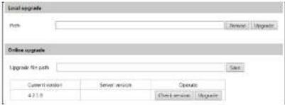
text_image
Local upgrade Name: Remove: Upgrade Online upgrade Upgrade Path: Start Current options Server services Operate 4.21.9 Ctrl Services Import-
Click the "Browse" button to select the save path of the upgrade file
-
Click the "Upgrade" button to start upgrading the firmware.
-
The device will restart automatically
Caution! Do not close the browser or disconnect the camera from the network during the upgrade.
For some specified models, online upgrade is available. The setting steps are as follows. If no such function, please skip the instruction.
-
Create the upgrade file location and save it.
-
Check the latest version by clicking "Check version".
-
Click "Upgrade" to update the firmware online.
6.8.4 Operation Log
To query and export log:
- Go to Config→Maintenance→Operation Log.
| Index | Time | Main Type | Sub Type | User Name | Login IP |
| 1 | 2015-07-14 11:19:18 | Operation | Log in | admin | 192.168.1253 |
| 2 | 2015-07-14 11:12:07 | Exception | Disconnected | 192.168.1253 | |
| 3 | 2015-07-14 19:12:17 | Exception | Disconnected | 192.168.1252 |
- Select the main type, sub type, start and end time.
- Click "Search" to view the operation log.
- Click "Export" to export the operation log.
7 Search
7.1 Image Search
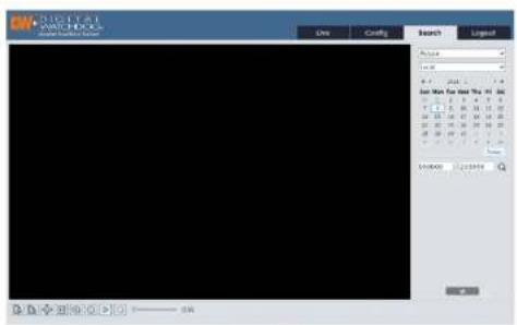
Click Search to go to the interface as shown below. Images that are saved on the SD card can be found here.
Note: If there is no SD card installed in the camera or the SD card is not compatible with the camera, a pop-up message will show stating that there is no card.
text_image
Digital WATCHBOOK Show the latest watch.com One Cancel Search Layout Access None 8.1 2000 1.0 User Men for Next One, Inc. 1 2 3 4 5 6 7 8 9 10 11 12 13 14 15 16 17 18 19 20 21 22 23 24 25 26 27 28 29 30 31 32 35 36 37 38 39 40 41 42 43 44 47 48 49 50 51 52 53 54 55 56 59 60 61 62 63 60 61 62 63 64 67 68 69 70 71 72 73 74 75 76 79 80 81 82 83 80 81 82 83 87 88 89 90 91 92 93 94 95 96 97 98 99 100 Inventory Inventory- Local Image Search
- Choose "Picture"—"Local".
- Set time: Select date and choose the start and end time.
- Click to search the images.
- Double click a file name in the list to view the captured photos as shown above.

natural_image
Interior view of a modern office or library space with glass flooring, tables, chairs, and a large screen (no visible text or symbols)Click to return to the previous interface.
- SD Card Image Search
- Choose "Picture"—"SD Card".

text_image
File My Land 1 2 3 4 5 6 7 8 9 10 11 12 13 14 15 16 17 18 19 20 21 22 23 24 25 26 27 28 29 30 31 32 33 34 35 36 37 38 39 40 41 42 43 44 45 46 47 48 49 50 51 52 53 54 55 56 57 58 59 60 61 62 63 64 65 66 67 68 69 70 71 72 73 74 75 76 77 78 79 80 81 82 83 84 85 86 87 88 89 90 91 92 93 94 95 96 97 98 99 100- Set time: Select date and choose the start and end time.
- Choose the alarm events at the bottom of the interface.
- Click to search the images.
| Icon | Description | Icon | Description |
| Close: Select an image and click this button to close the image. | Close all: Click this button to close all images. | ||
| Save: Click this button to select the path for saving the image on the PC. | Save all: Click this button to select the path for saving all pictures on the PC. | ||
| Fit size: Click to fit the image on the screen. | Actual size: Click this button to display the actual size of the image. | ||
| Zoom in: Click this button to digitally zoom in. | Zoom out: Click this button to digitally zoom out. | ||
| Slide show play: Click this button to start the slide show mode. | Stop: Click this button to stop the slide show. | ||
| Play speed: Play speed of the slide show. | |||
7.2 Video Search
7.2.1 Local Video Search
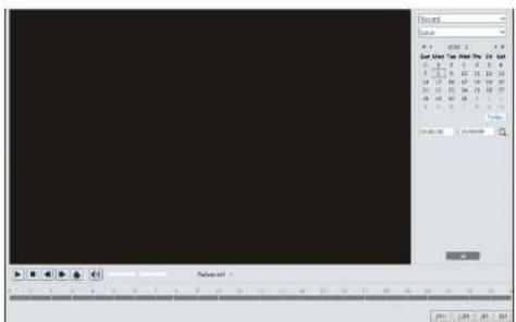
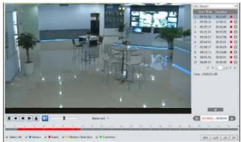
Click Search to go to the interface as shown below. Videos were recorded locally to the PC can be played in this interface.
text_image
Sound Scene 4.0 2008 3 4 Sound: 17.56 12.5 13.5 14.5 15.5 16.5 17.5 18.5 19.5 20.5 21.5 22.5 23.5 24.5 25.5 26.5 27.5 28.5 29.5 30.5 31.5 32.5 33.5 34.5 35.5 36.5 37.5 38.5 39.5 40.5 41.5 42.5 43.5 44.5 45.5 46.5 47.5 48.5 49.5 50.5 51.5 52.5 53.5 54.5 55.5 56.5 57.5 58.5 59.5 60.5 61.5 62.5 63.5 64.5 65.5 66.5 67.5 68.5 69.5 70.5 71.5 72.5 73.5 74.5 75.5 76.5 77.5 78.5 79.5 80.5 81.5 82.5 83.5 84.5 85.5 86.5 87.5 88.5 89.5 90.5 91.5 92.5 93.5 94.5 95.5 96.5 97.5 98.5 99.5 100% 100%
natural_image
Interior view of a modern office or library space with large windows, tables, chairs, and potted plants (no visible text or symbols)| Icon | Description | Icon | Description |
| Play button. After pausing the video, click this button to continue playing. | Pause button | ||
| Stop button | Speed down | ||
| Speed up | Watermark display | ||
| Enable / disable audio; drag the slider to adjust the volume after enabling audio. | |||
7.2.2 SD Card Video Search
Click Search to go to the Interface as shown below. Videos that were recorded on the SD card can be played in this interface.
Note: If the camera doesn't support SD card, please skip the instructions of SD card video search.
- Choose "Record"—"SD Card".
- Set search time: Select the date and choose the start and end time.
- Click to search the images.

text_image
3D Card File Edit View Tools Help 1 2 3 4 5 6 7 8 9 10 11 12 13 14 15 16 17 18 19 20 21 22 23 24 25 26 27 28 29 30 31 32 33 34 35 36 37 38 39 40 41 42 43 44 45 46 47 48 49 50 51 52 53 54 55 56 57 58 59 60 40.0000 - 0.0000 Referent Select All Select None Select Material Options Edit- Select the alarm events at the bottom of the interface.
- Select mix stream (video and audio stream) or video stream as needed.
- Double click on a file name in the list to start playback.
text_image
File Edit View 1 00:00:19 00:00:27 2 00:01:13 00:01:21 3 00:02:17 00:02:45 4 00:03:31 00:03:59 5 00:04:25 00:04:58 6 00:04:45 00:05:13 7 00:05:17 00:05:49 8 00:06:13 00:06:48 9 00:06:31 00:06:59 10 00:07:31 00:07:59 确定: 1998/01/08 Balance: Select All Select Event Media Controls CommonThe time table can be shown in 24H/12H/2H/1H format by clicking the corresponding buttons.
Video clip and downloading
- Click ↓ to download the video file in the PC.
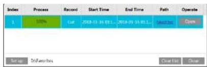
text_image
Index Process Record Start Time End Time Path Operate 1 100% Cut 2018-01-16 01:1... 2018-05-16 01:1... Ins Mr Setup DsnFarebox Cancel CloseClick "Set up" to set the storage directory of the video files.
Click "Open" to play the video.
Click "Clear List" to clear the downloading list.
Click "Close" to close the downloading window.
8 Appendix
Appendix 1 Troubleshooting
How to find the password?
A: Reset the device to the default factory settings.
Default IP: 192.168.226.201; User name: admin; Password: 123456
Fail to connect devices through IE browser.
A: Network is not well connected. Check the connection and make sure it is connected
well.
B: IP address is not available. Reset the IP address.
C: Web port number has been changed; contact administrator to get the correct port
number
D: Exclude the above reasons. Restore to default setting by IP-Tool.
IP tool cannot search devices.
It may be caused by the anti-virus software in your computer. Please exit it and try to
search device again.
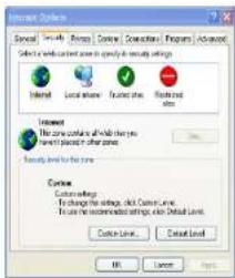
IE cannot download ActiveX control.
A. IE browser may be set up to block ActiveX. Follow the steps below.
① Open IE browser and then click Tools----Internet Options.

② Select Security----Custom Level...
(3) Enable all the options under "ActiveX controls and plug-ins".
④ Click OK to finish setup.
B. Other plug-ins or anti-virus blocks ActiveX. Please uninstall or close them.
text_image
Internet Options Special: Security Remote Control Accessories Programs Advanced Select a network-based power in any case to secure settings Internet Local source Fixed sites Network sites Internet The zone contains all other key Windows ports in other zones. Access Level for the zone Custom settings By changing the settings, click Context Level. To ensure the recommended settings, then Default Level. Custom Level... Cancel Level... OK Cancel Help
text_image
Security Settings Settings Enabling Emphasize signed network computer Enabling Promote Emphasize signed network controls Enabling Promote Emphasize and specific network controls not marked as safe Enabling Promote Enabling settings Breakfast: Enabling Reset OK CancelNo sound can be heard
A: Audio input device is not connected. Please connect and try again.
B: Audio function is not enabled at the corresponding channel. Please enable this function.
9 Dimensions
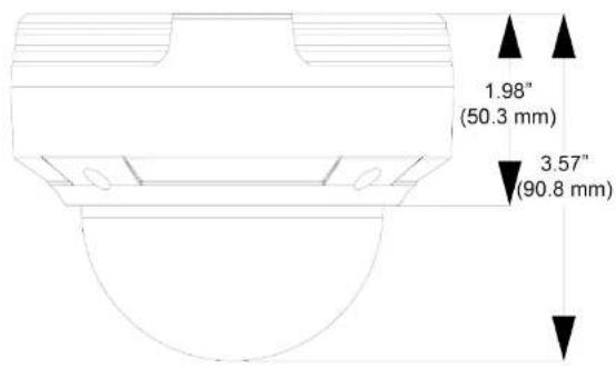
text_image
1.98" (50.3 mm) 3.57" (90.8 mm)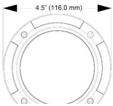
text_image
4.5" (116.0 mm)10 Warranty Information
Digital Watchdog (referred to as "the Warrantor") warrants the Camera against defects in materials or workmanships as follows:
Labor: For the initial five (5) years from the date of original purchase if the camera is determined to be defective, the Warrantor will repair or replace the unit with new or refurbished product at its option, at no charge.
Parts: In addition, the Warrantor will supply replacement parts for the initial five (5) years.
To obtain warranty or out of warranty service, please contact a technical support representative at 1+ (866) 446-3595, Monday through Friday from 9:00AM to 8:00PM EST.
A purchase receipt or other proof of the date of the original purchase is required before warranty service is rendered. This warranty only covers failures due to defects in materials and workmanship which arise during normal use. This warranty does not cover damages which occurs in shipment or failures which are caused by products not supplied by the Warrantor or failures which result from accident, misuse, abuse, neglect, mishandling, misapplication, alteration, modification, faulty installation, set-up adjustments, improper antenna, inadequate signal pickup, maladjustments of consumer controls, improper operation, power line surge, improper voltage supply, lightning damage, rental use of the product or service by anyone other than an authorized repair facility or damage that is attributable to acts of God.
11 Limits and Exclusions
There are no express warranties except as listed above. The Warrantor will not be liable for incidental or consequential damages (including, without limitation, damage to recording media) resulting from the use of these products, or arising out of any breach of the warranty. All express and implied warranties, including the warranties of merchantability and fitness for particular purpose, are limited to the applicable warranty period set forth above.
Some states do not allow the exclusion or limitation of incidental or consequential damages or limitations on how long an implied warranty lasts, so the above exclusions or limitations may not apply to you. This warranty gives you specific legal rights, and you may also have other rights from vary from state to state.
If the problem is not handled to your satisfaction, then write to the following address:
Digital Watchdog, Inc.
ATTN: RMA Department
5436 W Crenshaw St
Tampa, FL 33634
Service calls which do not involve defective materials or workmanship as determined by the Warrantor, in its sole discretion, are not covered. Cost of such service calls are the responsibility of the purchaser.

DIGITAL
WATCHDOG™
Complete Surveillance Solutions
Headquarters Office: 5436 W Crenshaw St, Tampa, FL 33634
Sales Office: 16220 Bloomfield Ave., Cerritos, California, USA 90703
PH: 866-446-3595 | FAX: 813-888-9262
www.Digital-Watchdog.com
technicalsupport@dwcc.tv
Technical Support PH:
USA & Canada 1+ (866) 446-3595
International 1+ (813) 888-9555
French Canadian 1+ (514) 360-1309
Technical Support Hours: Monday-Friday
9:00am to 8:00pm Eastern Standard Time