MegaPix CaaS DWC-MB44Wi650C2 - Surveillance Camera Digital Watchdog - Free user manual and instructions
Find the device manual for free MegaPix CaaS DWC-MB44Wi650C2 Digital Watchdog in PDF.

User questions about MegaPix CaaS DWC-MB44Wi650C2 Digital Watchdog
0 question about this device. Answer the ones you know or ask your own.
Ask a new question about this device
Download the instructions for your Surveillance Camera in PDF format for free! Find your manual MegaPix CaaS DWC-MB44Wi650C2 - Digital Watchdog and take your electronic device back in hand. On this page are published all the documents necessary for the use of your device. MegaPix CaaS DWC-MB44Wi650C2 by Digital Watchdog.
USER MANUAL MegaPix CaaS DWC-MB44Wi650C2 Digital Watchdog
DWC-MB44Wi650C1 - 128GB storage
DWC-MB44Wi650C2 - 256GB storage
natural_image
Close-up of a black DW surveillance camera with lens and control panel (no visible text or symbols)
text_image
Safety Information
CAUTION
RISK OF ELECTRIC SHOCK. DO NOT OPEN.

CAUTION:
TO REDUCE THE RISK OF ELECTRIC SHOCK, DO NOT REMOVE COVER (OR BACK) NO USER SERVICEABLE PARTS INSIDE. REFER SERVICING TO QUALIFIED SERVICE PERSONNEL.

Warning Precaution
This symbol indicates that dangerous voltage consisting a risk of electric shock is present within this unit.

This exclamation point symbol is intended to alert the user to the presence of important operating and maintenance (servicing) instructions in the literature accompanying the appliance.
WARNING
To prevent damage which may result in fire or electric shock hazard, do not expose this appliance to rain or moisture.
WARNING
- Be sure to use only the standard adapter that is specified in the specification sheet. Using any other adapter could cause fire, electrical shock, or damage to the product
- Incorrectly connecting the power supply or replacing battery may cause explosion, fire, electric shock, or damage to th product.
- Do not connect multiple cameras to a single adapter. Exceeding the capacity may cause excessive heat generation or fire
Precaution
Operating
- Before using, make sure power supply and all other parts are properly connected. - While operating, if any abnormal condition or malfunction is observed, stop using the camera immediately and contact your dealer.
Handling
- Do not disassemble or tamper with parts inside the camera. - Do not drop the camera or subject it to shock or vibration as this can damage the camera. - Clean the clear dome cover with extra care. Scratches and dust can ruin the quality of the camera image.
Installation and Storage
Do not install the camera in areas of extreme temperature
Important Safety Instructions
-
Read these instructions. - All safety and operating instructions should be read before installation or operation.
-
Keep these instructions. - The safety, operating and use instructions should be retained for future reference.
-
Heed all warnings. - All warnings on the product and in the operating instructions should be adhered to.
-
Follow all instructions. - All operating and use instructions should be followed.
-
Do not use this device near water. - For example: near a bath tub, wash bowl, kitchen sink, laundry tub, in a wet basement; near a swimming pool; etc.
-
Clean only with dry cloth. - Unplug this product from the wall outlet before cleaning. Do not use liquid cleaners.
-
Do not block any ventilation openings. Install in accordance with the manufacturer's instructions. - Slots and openings in the cabinet are provided for ventilation, to ensure reliable operation of the product, and to protect it from over-heating. The openings should never be blocked by placing the product on bed, sofa, rug or other similar surfaces. This product should not be placed in a built-in installation such as a bookcase or rack unless proper ventilation is provided and the manufacturer's instructions have been adhere to.
-
Do not install near any heat sources such as radiators, heat registers, or other apparatus (including amplifiers) that produce heat.
-
Do not defeat the safety purpose of the polarized or grounding-type plug. A polarized plug has two blades with one wider than the other. A grounding type plug has two blades and a third grounding prong. The wide blade or the third prong are provided for your safety. If the provided plug does not fit into your outlet, consult an electrician for replacement.
-
Protect the power cord from being walked on or pinched particularly at plugs, convenience receptacles, and the point where they exit from the apparatus.
-
Only use attachments/accessories specified by the manufacturer.
-
Use only with cart, stand, tripod, bracket, or table specified by the manufacturer, or sold with the apparatus. When a cart is used, use caution when moving the cart/apparatus combination to avoid injury from tip-over.
-
Unplug the apparatus during lightning storms or when unused for long periods of time.

Table of Contents
Introduction
Product & Accessories....5
Parts Name 6
Installation
Disassembling the Camera....7
Installation....8-11
Factory Reset....7
Cabling....12
SD Memory Card....13
Network Setup
DW IP Finder....14
Network Connection 15
DDNS Registration....16
Network Environments....17-19
Port Forwarding....20
Starting the IP Camera....21
Web Viewer
GUI Overview....22
Camera Settings
Setup > Video & Audio Setup > Video Configuration....23-26
Setup > Video & Audio > OSD Configuration....27
Setup > Video & Audio > Region of Interest Configuration 28
Setup > Video & Audio > Privacy Mask Configuration....29
Setup > Camera > Camera Image adjustment and Enhancement....30-35
Folius, Fomona, Vidal, Fokkermont
Introduction - Product & Accessories
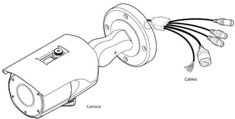
Please check if all the camera and accessories are included in the package.
text_image
Camera CablesIntroduction - Part Name

text_image
Sunshield Sunshield adjusting screws Lens Control board Pan/tilt stopper screw Bracket Control board capInstallation - Installation
Before installing your camera, you have to read the following cautions.
- You have to check whether the location can bear five times of the weight of your camera.
- Don't let the cable to be caught in improper place or the electric line cover to be damaged. Otherwise it may cause a breakdown or fire.
- When installing your camera, don't allow any person to approach the installation site. If you have any valuable things under the place, move them away.

text_image
Using the Template sheet, make the cabling h ① Using the template sheet① Using the Template sheet, make the cabling hole on
Installation - Cabling
Two Options
Use a PoE-enabled switch to connect data and power through a single cable and begin viewing and recording images instantly. A non-PoE switch will require an adaptor for power transmission.
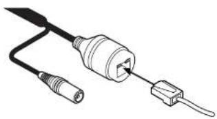
- Using a PoE Switch or PoE Injector
The Camera is PoE-compliant, allowing transmission of power and data via a single Ethernet cable.
PoE eliminates the need for the different cables used to power, record, or control the camera. Follow the illustration below to connect the camera to a PoE-enabled switch using an Ethernet cable.
- Not using PoE Switch or PoE Injector
If a PoE-enabled switch is not used, use a power adaptor for power transmission and non-PoE switch for data transmission.
Follow the illustrations below to connect the camera without a PoE-enabled Switch.
natural_image
Line drawing of a cable with two connectors, one connector inserted into a socket (no text or symbols)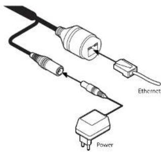
text_image
Ethemect PowerEthernet cable Ethernet cable
Installation -
Cabling
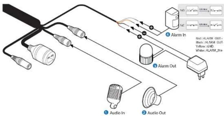
text_image
1 Audio In 2 Audio Out 3 Alarm Out 4 Alarm In Red: ALARM OUT= Black: ALARM OUT Yellow: GND White: ALARM JN+1 Audio In
Cable of the sensor/alarm input device should connect to alarm in+ and alarm in- of the cable slot.
2 Audio Out
It connects to the alarm lights, siren or lamps and the sensor types are normal open and normal close. Cable of the alarm output device should connect to alarm out+ and alarm out- of the cable slot.
If the speaker without the amplifier is connected to Audio Out port, it Out port, it doesn't work properly. Therefore, the speaker with the amplifier or the separate amplifier is needed.
3 Alarm Out
It connects to the alarm lights, siren or lamps and the sensor types are normal open and normal close.
Alarm & light bar + need to be connected with power + or adaptor +,
Alarm out+ need to be connected with Alarm - or light bar -. Alarm out- need to be connected with power - or adaptor -.
4 Alarm In
Cable of the sensor/alarm input device should connect to white and yellow line of the Alam cable.
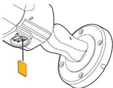
Installation - Inserting/Removing SD Memory Card
natural_image
Technical line drawing of a mechanical component with a yellow tag and mounting bracket (no text or symbols)The memory card is an external data storage device that has been developed to offer an entirely new way to record and share video, audio, and text data using digital devices.
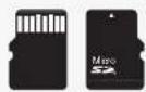
Recommended SD Card Specification (Not Included) - Type: Micro SD (SD/SDHC/SDXC) - Manufacturer: Transcend, Kingston, Toshiba, SanDisk - Capacity: 4GB\~128GB - Class: over UHS-I U3 Class 10

natural_image
Diagram of a mechanical component with a highlighted orange section, showing internal structure without any text or symbols.1 Inserting an SD Memory Card
Insert the SD card in the arrow direction.
Don't insert the SD memory card while it's upside down by force.
Otherwise, it may damage the SD memory card.
Use the tweezers when inserting or picking out the SD card.
2 Removing an SD Memory Card
Removing an SD Memory Card Gently press down on the exposed end of the memory card as shown in the diagram to eject the memory card from the slot.
- Pressing too hard on the SD memory card can cause the card to shoot out uncontrollably from the slot when released.
If you have saved data in the SD memory card, removing the SD memory card prior to setting record to OFF will cause damage to the data stored in the card.
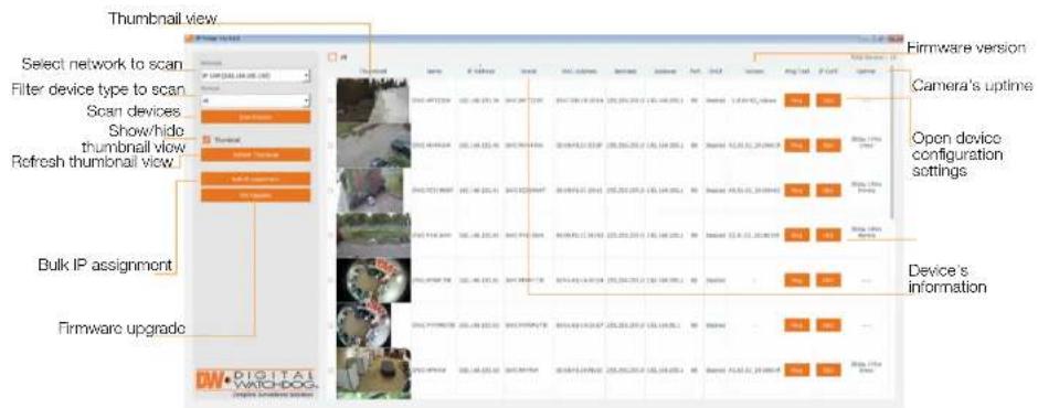
Network setup - DW IP Finder™
text_image
Thumbnail view Select network to scan Filter device type to scan Scan devices Show/hide thumbnail view Refresh thumbnail view Bulk IP assignment Firmware upgrade Firmware version Camera's uptime Open device configuration settings Device's informationGo to: http://www.digital-watchdog.com and search for 'IP Finder' on the quick search bar at the top of the page.
② The latest IP Finder software will appear in the search results. Click on the link to download the file to your computer.
3 The software will scan your network for all supported cameras and display the results in the tabel. Allow up to 5 seconds for the IP Installer to find the camera on the

text_image
Comms Settings Camera Name: DNC-ND421T8B MAC Address: 06.10F1.20.A4.9E IP Configuration Paths DNC Static IP IP Address: 253.150.1..103 Network: 253.252.250.0 Gateway: 152.108.1..1 DNS: 192.158.40.1 Ports Wall Part: 00Network Setup -
Quick Start of Network Connection
Please follow the steps below to complete the initial setup of the network function.
Please do not power on the IP Camera until instructed.
① Temporarily disable any proxy servers configured in internet Explorer.
If connecting the IP Camera directly to a modem, power down and reset the modem. Leave the modem powered down until configurations are finalized with the IP Camera and the IP Camera has been correctly connected to the modem.
- Connect the IP Camera and PC to the configured network.
- Open the IP Installer on a PC, then search for the IP camera.
If you have a DHCP server, it will automatically set the Camera IP.
If you do not have a DHCP server, Camera IP is set to 192.168.1.80 after one minute. In this case, PC IP must be changed to the IP to be able to access the 192.168.1.80. - If multiple numbers of camera are connected it should be distinguished by the mac address of the Camera.
- Click the Camera IP, and connect to the WEBPAGE.
- Default ID/Password to access IP Camera are both the word: admin.
- Familiarize yourself with the Viewer Interface Screen.
- please install VLC to display live video.
- The IP setting can be set to 'STATIC' at IP Installer or web viewer followed by Setup -> Network -> Network Settings
- If the IP Camera is connected to a network which utilizes a router, you must have Port Forwarding configured on your
11. Access your IP Camera via the Internet :
If you use a static IP address assigned by your ISP
1) Open Internet Explorer.
2) Type the IP of the IP Camera.
3) If you use a router, type the routers' static IP and the web port number of the IP Camera.
If you have a dynamic address provided by your ISP
1) Open Internet Explorer and visit the DONS website.
2) Register the IP Camera.
3) Reboot the IP Camera.
4) Give the DDNS server 10 minutes to locate your IP Camera's IP information.
5) Click the refresh button in the Internet Explore.
6) After your camera is connected, select your camera.
Network Setup - DDNS Registration
If you have DYNAMIC IP service from your Internet Service Provider (ISP), you can't tell the current IP address of the IP Camera. To solve this problem, you have to register to our DDNS service.
At first, you have to check if you are using dynamic addressing. If so, register your IP Video Server on our DDNS website before you configure, setup, or install the IP Camera.
Even though your IP is not dynamic, you will get benefit if you register to DDNS. In this case, just remember 'hostname.dyndns.com/gate1' instead of complicated series of numbers like http://201.23.4.76:8078.
For more details, contact our Support Center.
To use a public DDNS called 'dyndns' or 'no-ip', refer to the detail information on how to use the service. (Visit the web site: http://www.dyndns.com or http://www.no-ip.com)
Network Setup -
Guide to Network Environment
Please configure the IP Camera at the installation site. You must determine your network scenario in order to configure the IP Camera with the proper TCP/IP settings. This tutorial will guide you through the process. Before actually configuring the IP Camera, determine settings to be applied. Record those settings to be used to configure your IP Camera for reference.
When configuring your IP Camera, treat the IP Camera as another PC on your network. You will assign it several addresses and other TCP/IP properties to match your current network.
This step-by-step tutorial will teach what IP addresses and network configurations should be assigned based on the network scenario.
- The following descriptions are several basic network scenarios. Determine which scenario describes your network. If your network does not match one of the scenarios below and you are unsure how to setup your IP Camera, contact your network administrator and then call our Support Center.
You cannot control the rectangular gray areas and only the ISP has access to the devices.
- Before you begin, locate any Information and settings received from your Internet Service Provider (ISP). You may need to refer to these IP addresses at a later time during the configuration.
| Current TCP/IP Settings | |
| IP Address | |
| Subnet Mask | |
| Default Gateway | |
| Primary DNS Server | |
| Secondary DNS Server (Option) | |
Secondary DNS Server (Option)
Network Setup - Setup Case A, B

flowchart
graph LR
    A["Case A: Dynamic IP + Personal Router [Most SOHO"]] --> B["Camera"]
    B --> C["Personal Router (W/Integrated Switch)"]
    C --> D["Cable/DTL Medium (USB Provider)"]
    D --> E["Phone Line or CATY"]
    E --> F["Internet"]

flowchart
graph LR
    A["Internet"] --> B["Public Line"]
    B --> C["Gateway or Router at ICP"]
    C --> D["Personal Router W/Integrated Switch"]
    D --> E["PC"]
    F["Camera"] --> D
    style A fill:#f9f,stroke:#333
    style E fill:#ccf,stroke:#333
Configure your IP Camera's TCP/IP properties as follows :
-
Network Type: STATIC (even though you have Dynamic IP from your ISP, use STATIC on the IP Camera)
-
Internet Address: A private IP address such as 192.168.0.200 (Example)
You need to assign an IP address to the IP Camera just as you do with PC.
The IP address you assign must be unique to your network and match your network as well. For information on how to choose a unique IP and match your network, read the FAQ.
The IP address you assign must be a private IP. For information on how to choose a private IP please, read the FAQ.
- Subnet Mask: 255.255.255.0 (Example)
You must use the same subnet mask as the one you noted under 'Current TCP/IP Settings'.
- Default Gateway: 192.168.0.1 (Example)
① This IP address must be the IP address of your router. (private or LAN side)
Use the same Default Gateway you noted under 'Current TCP/IP Settings'.
- Preferred DNS Server: Use the 1st DNS Server from 'Assigned IP Address from My ISP'.
If you did not receive any IP addresses from your ISP, contact the ISP and acquire the IP address of their DNS server.
- DDNS Server : Use the DDNS server.
This is the same site you will register later to accommodate dynamic IP from your ISP.
Network Setup - Setup Case C, D

flowchart
graph LR
    A["Camera"] --> B["Cable/SSL Module (IP Provided)"]
    B --> C["Phone Line or Dial"]
    C --> D["Internal"]
Configure your IP Camera's TCP/IP properties as follows :
- Network Type: STATIC
- Internet Address: A static IP address received from your ISP such as 24.107.88.125 [Example]
You need to assign an IP address to the IP Camera just as you do with PC.
3. Subnet Mask : Subnet mask assigned from your ISP such as 255.255.255.240 (Example)
4. Default Gateway : 24.107.88.113 (Example)
Use the assigned default gateway from your ISP
5. Preferred DNS Server: Use the 1st DNS Server from 'Assigned IP Address from My ISP'
If you have not received any IP addresses from your ISP, contact them to acquire the IP address of their DNS server.
Case D:
Dynamic IP + DSL/Cable Modem [Connected directly to the IP Camera]
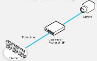
flowchart
graph LR
    A["Internet"] -->|Public Line| B["Gateway or Router at ISP"]
    B --> C["Camera"]
To connect the IP Camera directly to a modem, power down and reset the modem. Leave the modem powered down until configurations are finalized with the IP Camera and the IP] Camera has been connected correctly to the modem. Then power on the modem, followed by the IP Camera.
Configure your IP Camera's TCP/IP properties as follows :
- Network Type : DYNAMIC
- DDNS Server: Use the DDNS server
This is the same site you will register later to accommodate dynamic IP from your ISP. - Web Port: 80
You may select any number between 1025 \~ 60000.
Network Setup - Port Forwarding
After entering the correct TCP/IP settings, you are ready for 'Port Forwarding'(Cases A, B).
- Please record the TCP/IP settings of your IP Camera for future reference. You may need this information to access your IP Camera and to configure 'Port Forwarding'.
| IP Camera TCP/IP Settings | |
| IP Address | |
| Subnet Mask | |
| Default Gateway | |
| Preferred DNS Server | |
| DDNS Server | |
| Web Port | |
- After clicking 'Apply', the system will prompt for reboot. Please allow the system 50 seconds to reboot and accept the changes. After 50 seconds, close the configuration screen. The view will display 'Trying to Reconnect'. If the ACTIVE light on the IP Camera has gone off and is now back on again flashing, the IP Camera has rebooted. After the system reboots completely, remove the power supply from the unit and close Internet Explorer.
- Return your PC/Laptop TCP/IP properties to their original settings.
- Before installing the IP Camera, you must use 'Port Forwarding' on your personal router (Cases A, B).
You will need to forward 1 ports:
- Web Port
All the ports will be forwarded to the IP address you assigned to the IP Camera.
In the example above, you would forward:
- 8888 >192.168.0.200
Network Setup - Starting IP Camera
After forwarding correctly the Web Port, through your router (if applicable), install the IP Camera in a proper location.
- Locate the serial number located on the label attached to the bottom of the IP Camera, you will need this for DDNS registration.
- Connect the IP Camera to your router or cable/DSL modem (per your network scenario) via a Cat5/Se UTP Ethernet network cable.
- Supply power to the IP Camera.
- After 1 minute, verify the IP Camera indicators:
- LINK : Flickering/Solid
- After configuring Port Forwarding on your computer (If necessary), access your IP Camera on your local network by opening Internet Explorer and specifying the IP address and Web Port assigned to the IP Camera.
Examples: http://192.168.0.200:8888 or http://24.106.88.123 If you left your Web Port set to 80, do not need to specify the port in the Address Bar to access the IP Camera.
- Access your IP Camera via the Internet :
If you use Case B, C
1) Open Internet Explorer.
2) Type the IP of the IP Camera.
If you use Case A, D
1) Open Internet Explorer.
2) Visit the DDNSwebsite.
3) Register the IP Camera.
4) Give the DDNS server 10 minutes (MAX) to locate your IP Camera's IP information. You may reboot the server to send an immediate request to our DDNS server.
Web Viewer Screen -
Basic Screen
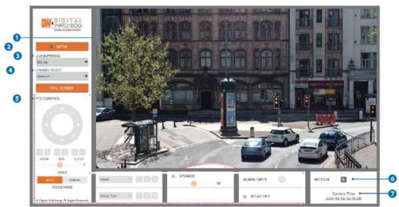
text_image
DIGITAL WATCHDOG 1 2 3 4 5 1 2 3 4 5 1 2 3 4 5 1 2 3 4 5 1 2 3 4 5 1 2 3 4 5 1 2 3 4 5 1 2 3 4 5 1 2 3 4 5 1 2 3 4 5 1 2 3 4 6 1 2 3 4 5 1 2 3 4 5 1 2 3 4 5 1 2 3 4 5 1 2 3 4 5 1 2 3 4 5 1 2 3 4 5 1 2 3 4 5※ Web viewer is optimized with explorer10 or above version and Firefox.
If VLC is not installed or VLC plugin is not supported (Chrome), Live buffering and Channel select menu on 3, 4 will be changed to Live Viewer menu, and then if HTMLS(MJPEG) is selected on Live Viewer menu, then you can check the video.
1 Live video display. This is the region for live video stream from the camera.
Setup nonun button. Click it to open the Setup nage to setup details of IP camera like Video Network Events System and etc.
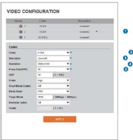
Setup - Video & Audio Setup
Video Configuration
1

text_image
V-VIDEO&AUDIO VIDEO OSI ROI PRIVACY MASK >CAMERA >C NETWORK >C TRIGGER ACTION >C EVENT'S >C EDGE >C SECURITY >C SYSTEM VIDEO CONFIGURATION Stream Codics Description 1 H.264 channel1 2 H.264 channel2 3 M-FPSI channel3 Codes Color: H.264 Description channel1 Resolution: 2500x1448 Frame Rate/FFSI: 30 GDP: 18 [1×100] Profile: High Smart Strate Control: Off Strate Mode: CDR Target Strate: 1616 [100%ps - 10%ms] Extension Option: Off Quality [1×10] © Digital Watchdog, All Rights Reserved. AffiY1 Detail Page - When you selects an item from the menu, you can set the details for the selected Item.
2 Setup Constitution
Video&Audio
[VIDEO, OSD, ROI, PRIVACY MASK]
Camera
Setup - Video & Audio Setup
Video Configuration
text_image
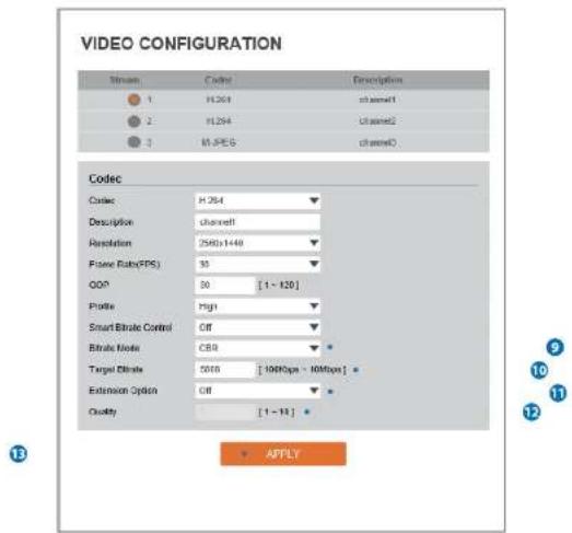
VIDEO CONFIGURATION Stream Codac Description 1 H:264 channel1 2 H:294 channel2 3 H:F:56 channelC Codec Codac H:264 Description channel1 Resolution 2590x1440 Frame Rate(FPS) 30 GDP 30 [1 - 120] Profile High Smart Bitrate Control Off Bitrate Mode CBR Target Bitrate 5010 [10Kbps - 10Mbps] Extension Option Off Quality [1 - 18] APPLYLive Video Channel Setup - The video can be configured to variety settings with a combination of codec and resolution. The camera performance has to be considered when setting multiple channels. This effects on the performance of the camera.
2 Codec - Choose the video codec. According to the selected codec, the subcategories can be changed automatically.
3 Description - Input the additional description about the selected channel. Max. 30 alphabets are allowed (Including space). For the description, English alphabet characters and special characters?
Setup - Video & Audio Setup
Video Configuration
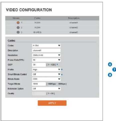
text_image
VIDEO CONFIGURATION Stream Codec Description 1 H.264 cchannel1 2 H.254 cchannel2 3 H.PES cchannelC Codec Codec H.264 Description channel1 Resolution 2590x1440 Frame Rate(FPS) 30 GDP 30 [1 - 120] * Profile High Smart Bitrate Control Off Bitrate Mode CBR Target Bitrate 5010 [10Kbps - 10Mbps] Extension Option Off Quality [1 - 18] APPLYGOP(Group of Pictures) Size - Set up the number of frames (P-frame) which contain only changed information based on basic frame (I-frame). Regarding videos with lots of movement, if you set GOP size bigger, only the number of P-frames is bigger. As a result, video resolution will be low but 'File size' and 'Bit-rate can be decreased.
GDP(Group of Pictures) Size is..
I-frame and P-frame can be created for MPEG4 and H.264 video compression. I-frame (=key-frame) means the whole image data for one specific scene of video. P-frame is image data which has been changed information compared to I-frame GOP is made up of one I-frame and corresponding several P-frame. To improve video quality, set the number of D-frame smaller and to decrease importance, set the number of D-frame higher.
Setup - Video & Audio Setup
Video Configuration
text_image
VIDEO CONFIGURATION Stream Codict Description 1 H.264 channel1 2 H.264 channel2 3 M.PES channel0 Codec Codec H.264 Description channel1 Resolution 2500x1448 Picture Ratio(FPS) 30 QOP 30 [1 - 120] Profile Pigh Smart Bitrate Control Off Bitrate Mode CBR Target Bitrate 5018 [100fps - 10Mbps] Extension Option Off Quality [1 - 11] AFTLY9 Bitrate Mode - Select the bitrate control scheme of video compression from CBR (Constant Bit Rate) or VBR (Variable Bit Rate).
CBR - To guarantee the designated constant bit rate, the quality of video are controlled in this mode. Therefore, the quality of video is likely to be varying when network traffic is changing.
VBR - To guarantee the designated quality, the bit rate of video stream is changed in this mode. Therefore, the frame rate of video is likely to be varying when network traffic is changing.
Setup - Video & Audio Setup
OSD Configuration

text_image
ON SCREEN DISPLAY(OSD) CONFIGURATION Date & Time Off On Position X [0 - 100] Position Y [0 - 100] User Text Off On Position X [0 - 100] Position Y [0 - 100] Text APPLY1 Date / Time - Display the current time.
2 User Text - Output the TEXT entered by the user. Support a maximum of 30 characters.
3 Click 'Apply' to make above setting effective.
Setup - Video & Audio Setup
Region of Interest Configuration

text_image
REGION OF INTEREST CONFIGURATION Stream Channel Activation Enable Quality 50% SAVE CANCELRegion of interest function gives much more efficiency picture quality for indicated area to improve picture qualities of movement scene at the same bandwidth.
1 Stream - Select the Stream.
Currently it supports only Channel1.
Activation • The Region of Interest can be enable or disable.
Setup - Video & Audio Setup
Privacy Mask Configuration
text_image
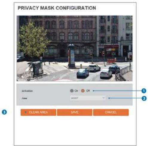
PRIVACY MASK CONFIGURATION Activation On Off Area Area1 CLEAR AREA SAVE CANCELUse this function to mask areas that you want to hide on screen to protect privacy.
1 Activation - The Privacy mask function can be enable or disable.
2 Area - Select the Area1 \~ Area16 and Set the privacy area.
A. This is not to save the current solution.
Setup - Camera Setup
Camera Image Adjustment
text_image
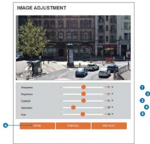
IMAGE ADJUSTMENT Sharpness + 51 + Brightness + 51 + Contrast + 51 + Saturation + 26 + Hue + 49 + SAVE CANCEL DEFAULT1 Sharpness - Using this control, sharpness of image can be adjusted to meet your preference.
2 Brightness - Using this control, brightness of image can be adjusted to meet your preference.
3 Contrast - Using this control, contrast of image can be adjusted to meet your preference.
Saturation. Using this control. Saturation of images can be adjusted to meet your preferences.
Setup - Camera Setup Camera Exposure Settings
text_image
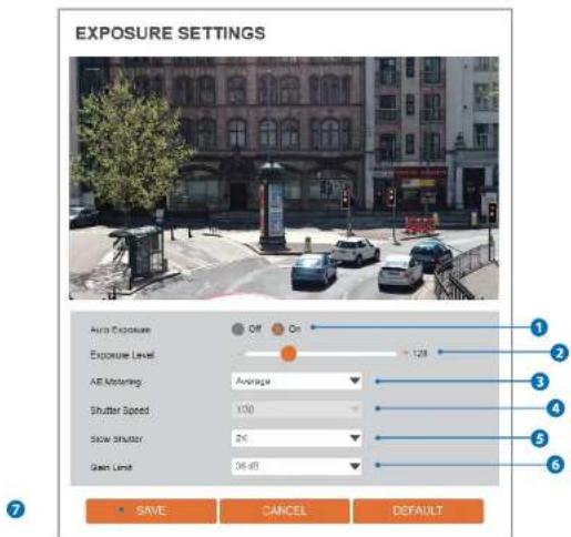
EXPOSURE SETTINGS Auto Exposure Off On Exposure Level 128 All Motoring Average Shutter Speed V30 Slow Shutter 2K Gain Limit 36 dB SAVE CANCEL DEFAULT1 Auto Exposure - Automatic exposure(AF) automatically sets the aperture or shutter speed, based on the external lighting conditions for the photo.
2 Exposure Level - If this value is increases, the image becomes brighter.
3 AE metering - AE metering mode refers to the way in which a camera determines the exposure.
Setup - Camera Setup
Camera Day & Night Settings

text_image
DAY&NIGHT SETTINGS Day & Night Auto Day Night Schedule Color Level 5 BW Level 5 Transition Time Middle Day -> Night Time 10 00 Night -> Day Time 5 00 SAVE CANCEL DEFAULT1 Day & Night
-Auto: In this mode, the IR cut filter is removed automatically depending on the light condition around.
- Day: In this mode, the IR cut filter is applied to the Image sensor all the time. Thus, the sensitivity will be reduced in the dark light condition but the better color reproduction performance are obtained.
-Night: In this mode, the IR cut filter on the Image sensor is removed all the time. The sensitivity will be enhanced in the dark light condition but the image is black and white.
Schedule in this work. Non/White needs is connected accordance with the calculated time
Setup - Camera Setup
Camera Backlight Settings

text_image
BACKLIGHT SETTINGS WDRWide Dynamic Range: OFF WDR Level Name SAVE CANCEL DEFAULTThis is a feature used for problematic light conditions where the contrast from light to dark areas is very high.
1 WDR (Wide Dynamic Range) - The WDR function can be enable or disable.
2 WDR Level - Select the WDR level depending on the difference in brightness between the darkest and lightest part of an image.
Click 'Save' to save the current settings
Setup - Camera Setup Camera White Balance
text_image
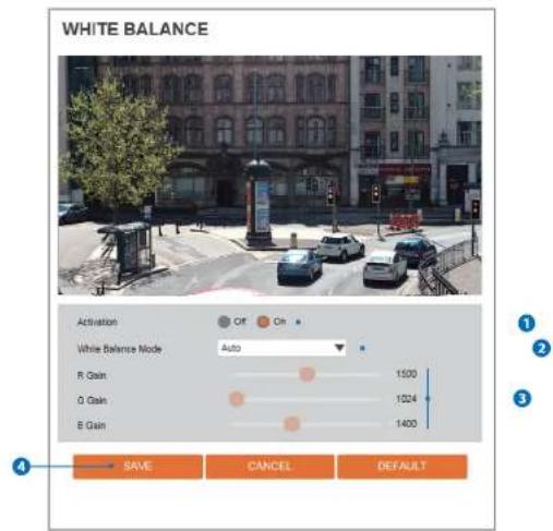
WHITE BALANCE Activation Off On White Balance Mode Auto R Gain 1500 O Gain 1024 B Gain 1400 SAVE CANCEL DEFAULT1 Activation - White Balance can be enable or disable.
2 White Balance Mode - Select White Balance depending on the lighting conditions.
3 RGB Gain - The R/G/B gain can be set only when the White Balance Mode is set to Manual.
A. Click Point to save the current solution
Setup - Camera Setup
Camera Image Enhancement
text_image
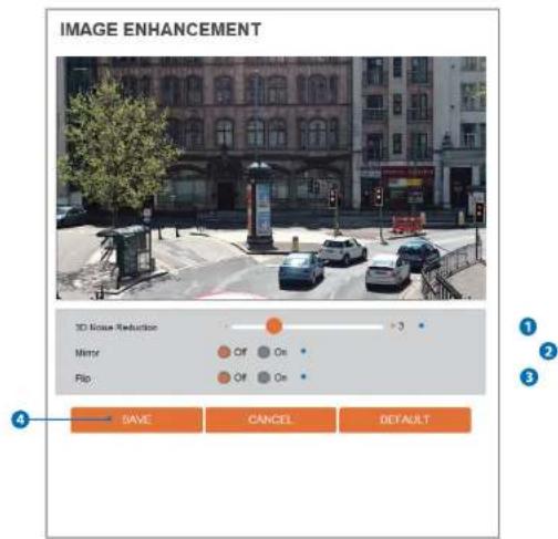
IMAGE ENHANCEMENT 3D Image Reduction Minry Flip +3 Off On Off On SAVE CANCEL DEFAULT3D Noise Reduction - 3DNR function enables to suppress noise and retain good video quality in low light conditions.
2 Mirror - Reverse the video from side to side.
3 Flip - Reverse the video from up to down.
High level to save the current solution
Setup - Camera Setup
Video Enhancement
text_image
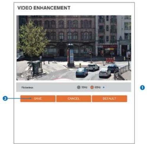
VIDEO ENHANCEMENT Flickiness 50Hz 60Hz SAVE CANCEL DEFAULT1 Flicker - This function Enable to enhance the flicker situation.
2 Click 'Save' to save the current settings.
Click 'Cancel' to return to the previous setting.
Click 'Default' to settings to the factory defaults.
Setup - Network Setup
Network Status
NETWORK STATUS
| MAC Address | 001033F 2F 8C 03 |
| IP Address | 192 168.1.44 |
| Subnet Mask | 255 265 3.0 |
| Default Gateway | 192 168.1.1 |
| Preferred DNS Server | 200 246 252.2 |
| Alternate DNS Server | 164 124 101.2 |
| HTTP Port | 80 |
| HTTPS Port | 443 |
| RTSP Port | 554 |
This menu will show you all the information of Network setting in the camera. However, you cannot change those here.
Setup - Network Setup
Network Settings
text_image
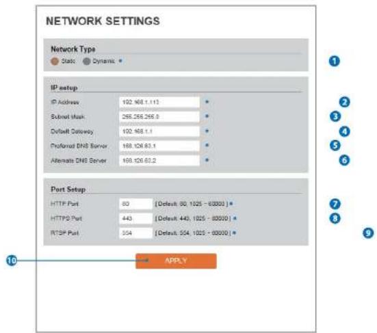
NETWORK SETTINGS Network Type Static Dynamic IP setup IP Address 102.168.1.113 Submit Mask 265.266.266.0 Default Gateway 102.168.1.1 Professional DNS Server 168.126.83.1 Alternate DNS Server 168.126.83.2 Port Setup HTTP Port 80 [Default: 80, 1025 - 8000] HTTPD Port 443 [Default: 443, 1025 - 8000] RTSP Port 304 [Default: 504, 1025 - 8000] APPLYNetwork Type - Define network IP address type from the Static Mode for the fixed IP or the Dynamic Mode by the dynamic IP address. If you select the Static Mode, you must fill out IP Address, Subnet Mask, Gateway, DNS Server and all ports. If you select the Dynamic Mode, the IP address will be allocated automatically by DHCP equipment. If you click the Apply button to update changes, the system will be re-booted. In this case, you have to reconnect the camera using new IP address.
2 IP Address - Define the IP address. The address is consisted of four numbers separated by dots and the range of each number is from 0 to 10.
Setup - Network Setup
Auto IP Settings

text_image
AUTO IP SETTINGS General Setting Off On UNIQUE ID a032e1fb-8621-4e35-0202-86e415d074e5 AUTO IP ADDRESS 189.254 188.3 APPLY1 General Setting - Auto IP Settings function can be enable or disable.
2 Auto IP Settings Information - It displays the unique id or Auto IP address.
3 Click 'Apply' to make above setting effective.
Setup - Network Setup
ONVIF Settings
text_image
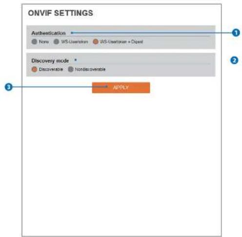
ONVIF SETTINGS Authentication None WS-Userhaven WS-Userhaven + Digest Discovery mode Discoverable Nondiscoverable APPLY1 Authentication
None: Allows to access without ONVIF authentication.
WS - Usertoken: Allows to access with WS-User Token of ONVIF authentication.
WS - Usertoken + Digest: Allows to access with WS-User Token and Digest of ONVIF authentication.
2 Discovery Mode - The discovery function can be enable or disable.
Setup - Network Setup
UPNP Settings
text_image
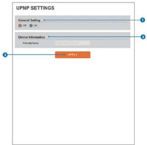
UPNP SETTINGS General Setting Off On Device Information Friendly Name APPLYGeneral Setting - UPNP function can be enable or disable.
2 Friendly Name - Define the friendly name. Click
③ 'Apply' to make above setting effective.
Setup - Network Setup
DDNS Settings

text_image
DDNS SETTINGS Disable Public DONS Address www.noip.com Host Name: User Name: Password: 1 2 3 APPLY1 DDNS Disable - If it is selected, DDNS service does not work.
2 Public DDNS - To use public DDNS service, select a site address listed in the list. After filling out the Host Name of the site, the setup is completed by entering User Name and Password registered in that DDNS site.
| DDNS Provider | Site Address |
| DunDNS | www.dundar.com |
Setup - Network Setup
FTP Settings

text_image
FTP SETTINGS General Setting Off On Server Information FTP Server Address FTP Upload Path FTP Port User ID Password APPLYTo transfer / save the image to the relevant sites through FTP, then FTP needs to be setup.
General Setting - FTP function can be enable or disable.
2 FTP Server Address - Define FTP Server IP Address. If IP Address form is incorrect, a Message box will be shown to try again.
STR Unlead Path. Defining search in STR conjugate store video. Earth-growth game. English Alshakote numbers and social characters.
Setup - Network Setup
SMTP Settings
text_image
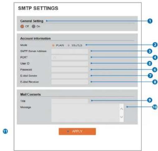
SMTP SETTINGS General Setting Off On Account information Mode PLAN SS/TLS SMTP Server Address PORT User ID Password E-Mail Gender E-Mail Receiver Mail Comments Title Message APPLYTo send / save the image to the relevant sites by Email, SMTP needs to be setup.
General Setting - SMTP function can be enable or disable.
2 Mode - Select Security mode of SMTP from Plain or SSL / TLS. After checking account setup of your SMTP Server, you may select one.
A CHATN Common Address: Online the CHATN Common Address. If the ID Address form is increased a Message law will be shown to increase
Setup - Network Setup
SNMP Settings
text_image
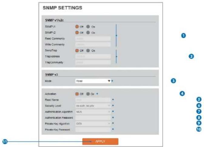
SNMP SETTINGS SNMP v1/v2c SNMP.v1 Off On SNMP.v2 Off On Read Community Write Community SwapTrap Off On TrapAddress TrapCommunity SNMP v3 Mode Read Activation Off On Read Name Security Level on such No play Authentication Algorithm MCS Authentication Password Private-Key Algorithm DCS Private-Key Password APPLYSNMPv1/SNMPv2 - Select the SNMPv1/SNMPv2 option and type the names of Read community and Write community.
SNMP trap can be used to check periodically for operational thresholds or failures that are defined in the MIB.
2 SNMP Trap - SNMP trap can be enable or disable.
CHAND contains considerable possibility: a higher probability level which allows you to set the Authentication protocol and the Examination
Setup - Network Setup
RTSP Information
text_image
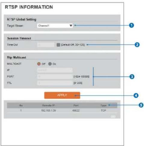
RTSP INFORMATION RTSP Global Setting Target Stream: Channel1 Session Timeout Time Out: Default Off, 30-120 Rip Multicast MULTICAST Off On IP PORT (1024-00000) TTL (0-255) APPLY No Remote IP Port Type 1 162.168.1.39 49622 TCP1 Target Stream - Select the channel you want to set.
2 Time out - Set the RTSP time out.
The session is disconnected after the specified time out
3 RTP Multicast - Check RTP Multicast On/Off. To activate RTP Multicast.
Setup - Trigger Action Setup Action Rules Configuration
text_image
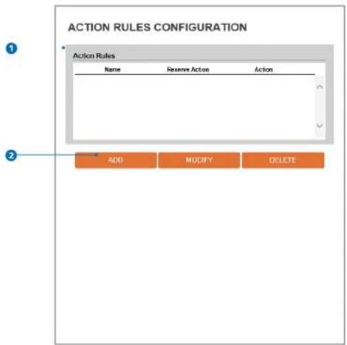
ACTION RULES CONFIGURATION Action Rules Name Reserve Action Action ADD MODIFY DELETE1 Action rules List - It indicates the custom action rule information added to Action rules list.
2 Click 'Add' to add custom action rules.
- Click 'Modify' to modify selected item from the action rules list.
- Click 'Delete' to delete selected item from the action rules list.
Setup - Trigger Action Setup Action Rules Add / Modify

text_image
ACTION RULES CONFIGURATION General Setting Name NewAction Action1 NONE Action2 NONE Action3 NONE Action4 NONE Action5 NONE SAVE CANCEL1 Name - Define name of action rules.
2 Action1 \~ Action5 - Select the action to take if the event occurs.
3 Click 'Save' to save the current settings.
Click 'Cancel' to return to the previous menu.
Setup - Trigger Action Setup Image Transfer Configuration

text_image
IMAGE TRANSFER CONFIGURATION Pre/Post Alarm Image Number Of Image 2 Image Per Second(s) [ 1 - 5 ] Pre-Alarm Duration 3 Seconds[ 1 - 5 ] Post-Alarm Duration 3 Seconds[ 1 - 30 ] APPLY1 Pre / Post Alarm Image - Image Transfer due to event is configured by setting image transfer rate and Pre / Post alarm duration.
| Descriptions | |
| Number of Image | Define Number of Image transferred per second. |
| Per alarm Duration | Define duration of image transfer before or event. |
Setup - Event Setup
Event Rules Configuration

text_image
EVENT RULES CONFIGURATION Event Rules Name Reserve Event Schedule Action NewRule Motion Detection Always SNTP NewRule2 Network Disconnected Always FTP ADD MODIFY DELETEEvent Rules List - It Indicates the custom Event Rule Information added to Event Rules list.
2 Click 'Add' to add custom event rules.
- Click 'Modify' to modify selected item from the event rules list.
- Click 'Delete' to delete selected item from the event rules list.
Setup - Event Setup
Event Rules Configuration

text_image
EVENT RULES CONFIGURATION General Name NewRule Event Condition Event NONE Action Rules NONE SAVE CANCEL1 Name - Define the Event rule name.
2 Event - Select the event among motion detection, network disconnection, temperature critical.
* Click 'Cancel' to return to the previous setting.
You need a event one more.
3 Rules - Select the action rule defined in the Trigger Action-Action rule menu.
Setup - Event Setup
Motion Detection Configuration
text_image
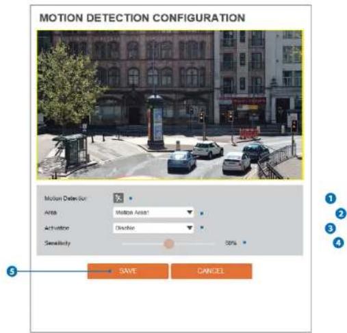
MOTION DETECTION CONFIGURATION Motion Detection Area: Motion Area! Activation: Discrete Sensitivity: 50% SAVE CANCEL1 Motion Detection - It shows the Motion event status.
Event Alert Icon! Appears if 'Motion Detection' is activated.
2 Area - Set the motion detected area.
You can set up to four areas.
Alication: Freshly on Disksible motion detection function
Setup - Event Setup
Temperature
text_image
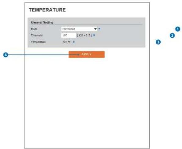
TEMPERATURE General Setting Mode: Farrehselt Threshold: 150 [120 - 312] Temperature: 120 °F APPLY1 Mode - Select the either Fahrenheit and Celsius.
2 Threshold - Define the temperature at which the event trigger is occurred.
3 Temperature - It indicates the current temperature of the IP camera.
2014年1月1日
text_image
DW SPECTRUM® EDGE Version 8.1.0.17722 Status Spectrum Edge is installed mediaserver is running with pid 405 server is allow Spectrum Edge Instal Select File DW Spectrum® Edge Control START STOP RESTART REMOVEVersion - Displays the version of DW Spectrum® edge (media server) installed in the camera.
Status - Displays the status of the DW Spectrum ^® edge (media server) installed in the camera. Wait until the status of the server is marked as 'alive'.
3 Select a new version of DW Spectrum® edge (media server) file to update and upload.
Setup - Edge Setup
Storage Configuration
- IF SD Card does not automatically mount, you must format for mounting SD card.
| Name | Mounted | Size | Used(%) | Available |
| seconds | 0 | 29.5G | 4% | 28.5G |
Display the SD card information mounted from device.
When you select the item in Storage list, You can set the functions related to the SD card.
Setup - Edge Setup
Storage Configuration

text_image
STORAGE CONFIGURATION Notice 1. IF SD Card does not automatically mount, you must format for mounting SD card. SD CARDID Storage Size 4.0K / 7.4G Unmount UNMACOUNT Format FORMAT1 Storage Size - Total capacity of SD card and the remainder of It are displayed.
2 Unmount - Remove the SD card from the device. UNMOUNT cannot be done when EDGE (Media server) is running.
3 Format - Delete the all contents that stored in SD card. FORMAT cannot be done when EDGE (Media server) is running..
Setup - Security Setup
IP Address Filter Configuration

text_image
IP ADDRESS FILTER CONFIGURATION General Setting IP Address Filter Off Off IP Filter Type Allow APPLY Filtered IP Address* IP Address IP Address [Innle] ADD REMOVE REMOVE ALLIP Address Filter - IP filter function can be enable or disable.
2 IP Filter Type - Select the recording IP filter type.
3 Click 'Apply' to make above setting effective.
File in Address Disclusts filed in address
Setup - Security Setup
RTSP Authentication Configuration
text_image
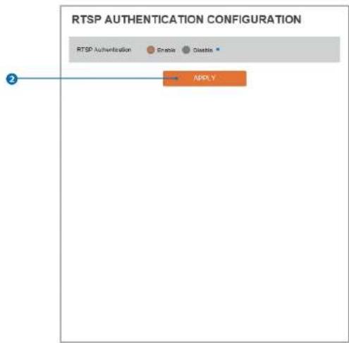
RTSP AUTHENTICATION CONFIGURATION RTSP Authentication Gracia Glastia APPLY①
1 RTSP Authentication - RTSP Authentication can be enable or disable.
2 Click 'Apply' to make above setting effective.
Setup - Security Setup
IEEE 802.1X Configuration

text_image
IEEE 802.1X CONFIGURATION General Setting IEEE 802.1X On Off Protocol MDS EAQOL Version 1 ID Passroom Unity CA Certificates NONE Certificates NONE APPLYThe feature is needed when connecting the camera to the network protected by the IEEE 802.1X.
1 IEEE 802.1x - The IEEE 802.1x feature can be enable or disable.
2 Protocol
- MDS : It provides one-way password-based network authentication of the client.
Setup - Security Setup
HTTPS Configuration
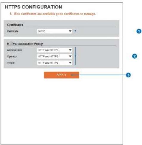
text_image
HTTPS CONFIGURATION 1. If no certificates are available go to certificates to manage. Certificates Certificate NONE HTTPS connection Policy Administrator HTTP and HTTPS Operator HTTP and HTTPS Viewer HTTP and HTTPS APPLYHTTPS encrypts session data over SSL or TLS protocols instead of using plain text in socket communications.
1 Certificate - Select an Installed certificate.
If you can not select a certificate, please install the certificate from the Security->Certificates menu.
2 HTTPS connection Policy - Select one of "HTTP", "HTTPS", "HTTP and HTTPS" depending on the connected user authority.
Setup - Security Setup
Certificates Configuration

text_image
CERTIFICATES CONFIGURATION Server/Client Certificates * Certificate Name Issued On Expires On CREATE SELF-SIGNED CERTIFICATE PROPERTIES DELETE CREATE CERTIFICATE SIGNING REQUEST INSTALL CERTIFICATE CA Certificate * Certificate Name Issued On Expires On DigitCertAmountIDRootCA 2006-11-10 2031-11-10 ExplicitCharacterRootCA 2006-11-10 2031-11-10 DigitCertHighAssumeIDRootCA 2006-11-10 2031-11-10 GeoTrust_Dietal_CA 2003-05-21 2022-05-24 GeoTrust_Dietal_CA2 2004-03-04 2018-03-04 GeoTrust_Primary_CA 2006-11-27 2038-07-17 INSTALL CERTIFICATE PROPERTIES DELETE1 Server/Client Certificates - It show the installed certificates.
2 Create Self-Signed Certificate - A self-signed SSL certificate is an identity certificate signed by its own creator, but they are considered to be less trustworthy.
A
Setup - Security Setup
Certificates Configuration

text_image
CERTIFICATES CONFIGURATION Create Self-Signed Certificate Limit Name: Available On: Entry: on: on: on: on: on: on: on: on: on: on: on: on: on: on: on: on: on: on: on: on: on: on: on: on: on: on: on: on: on: on: on: on: on: on: on: on: on: on: on: on: on: on: on: on: on: on: on: on: on: on: n Country: U.S. State Of Provision: Location: Organization: Organization Ltd. Limit Name: 102.146.1.518 File: 4336 Type: OK CANCEL Install Certificate Certificate Type Shipping Program Certificate Type Shipping Key Use Program Key PRO/CALE Passivated Certificate Name: Certificate File Import File OK CANCEL Install CA Certificate Certificate Name: Certificate No: Import File OK CANCEL 1 2 3 4 5 6 7 8 9 10Detail for Install Certification.
1 Certificate From Signing Request - Select to install signed certificate returned from the CA.
2 Certificate And Private Key - Select to install Certificate And Private Key to install a certificate and private key.
- Use Separate Key : Too install certificate uploading Certificate and Private Key file.
Setup - Security Setup
Service Configuration
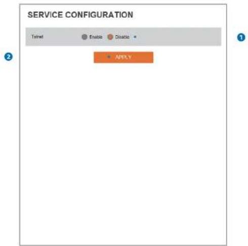
text_image
SERVICE CONFIGURATION Telnet Enable Disable APIPLV1 Telnet - The Telnet function can be enable or disable.
2 Click 'Apply' to make above setting effective.
Setup - System Setup
System Information
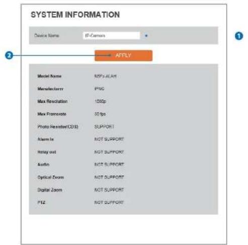
text_image
SYSTEM INFORMATION Device Name: IP-Census AFTLY Model Name: NFFLAALH Manufacturer: P10C Max Resolution: 100p Max FRAMORATE: 30 fps Photo Reactor(C335) SUPPORT Alarm Is NOT SUPPORT Retry out NOT SUPPORT Audio NOT SUPPORT Optical Zoom NOT SUPPORT Digital Zoom NOT SUPPORT P12 NOT SUPPORTSystem Capability information.
1 Device Name - You can define the device name.
2 Click 'Apply' to make above setting effective.
Setup - System Setup
Firmware Update

text_image
FIRMWARE UPDATE Notice 1. Do not power off during update. It may cause total system damage. 2. If Explorer was closed abnormally or a user closed accidentally while uploading firmware file, please try again after 30 seconds. 3. Please do not select other menus while updating firmware file. Version Information System 2016.4.22_0.3.3 Camera 0.1 Web update Firmware File Select/Files START FORM UPDATE FTP user information FTP Server Address Up/lets/iv FTP Port 21 User ID dempie Password ***** FTP Upload Path 1 SAVE CANCEL CHECK1 Version Information - It shows the current Firmware Version in the system.
2 Web Update - Select the Firmware file in your computer by clicking [Select file] button.
3 Start F / W Update - Click this button to start update. Progress of uploading will be displayed using Progress Bar. If you assign the wrong file name, an error massage will be shown.
Setup - System Setup
Firmware Update

text_image
FIRMWARE UPDATE Notice 1. Do not power off during updates. It may cause total system damage. 2. If Explorer was closed abnormally or a user closed accidentally while uploading firmware file, please try again after 30 seconds. 3. Please do not select other menus while updating firmware file. Version Information System 2016.4.22_0.8.3 Camera 0.1 Web update File name File Select File START FORM UPDATE FTP user information FTP Server Address fp.drcn.lv FTP Port 21 User ID 0mplus Password ***** FTP Uploaded Path / SAVE CANCEL CHECKFTP Server Address - Define FTP Server IP Address. If IP Address form is Incorrect, a Message box will be shown to try again.
5 FTP Port - Define the FTP Server Port. If Port is not appropriate, it is impossible to access to FTP Server.
6 User ID - Define User ID to access to the FTP Server. Fill out the correct User ID registered in the FTP Server.
Setup - System Setup
Date & Time Settings
text_image
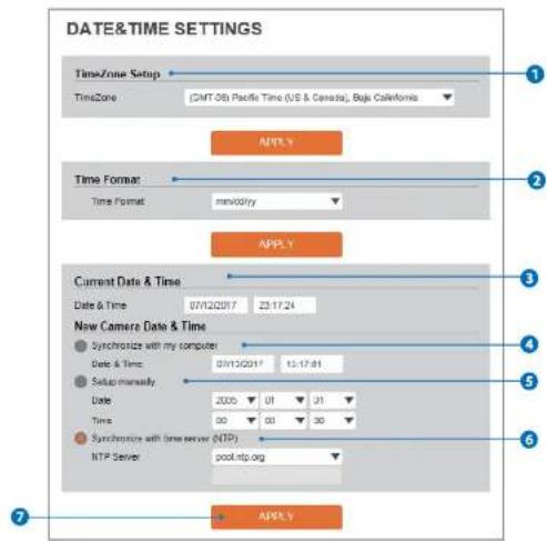
DATE&TIME SETTINGS TimeZone Setup TimeZone (GMT-08) Pacific Time (US & Canada), Baja California APPLY Time Format: Time Format: mm/day APPLY Current Date & Time Date & Time 07/12/2017 23:17:24 New Camera Date & Time ● Synchronize with my computer Date & Time 07/12/2017 15:17:01 ● Setup manually Date 2005 01 31 Time 00 03 30 ● Synchronize with time server (NTP) NTP Server pool.ntp.org APPLY1 TimeZone Setup - Choose TimeZone for camera. It will be activated after clicking 'Apply' button.
Prior to setting below 'New Camera Date & Time', set correct Timezone first.
2 Time Format - Select the time format yy-mm-dd or mm/dd/yy.
3 Current Date & Time - Shows the current date and time setting in the Camera.
Setup - System Setup
Users Management
text_image
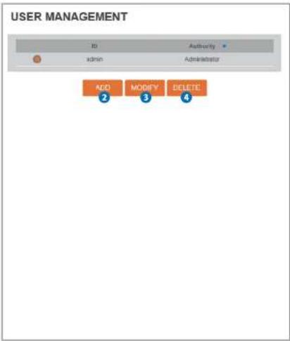
USER MANAGEMENT ID Authority admin Administrator ADD MODIFY BELETE ② ③ ④1
1 Users - List all the user accounts for authentication.
2 Add - Register a new user

Setup - System Setup
System Log

text_image
SYSTEM LOG Filter Date Time Type Sort Change Deciding 1 2 3 4 5 6 7 8 9 10 1 2 3 4 5 6 7 8 9 10 REFRESH LIST List Date & Time Log IP 2005/01/01-00:07:14 Change video encoder config 192.168.1.39 2005/01/01-00:00:25 RTSP session connected 192.168.1.39 2005/01/01-00:00:19 RTSP session connected 192.168.1.39 2005/01/01-00:00:17 RTSP session connected 192.168.1.39 2005/01/01-00:00:15 Network initialized system 2005/01/01-00:00:15 Sensor alarm assumed : 1 : Off system 2005/01/01-00:00:15 System initialized system 2005/01/01-00:45:47 System terminated system 2005/01/01-00:45:46 Factory default 192.168.1.39 1 2 3 4 5 6 7 8 9 101 Filter - Select a date, sort or type of log to filter the log.
2 Click the 'Refresh' button to refresh the log list,
Click 'Filter' to view the filtered log.
3 System Log List - The filtered log is displayed.
Setup - System Setup
Factory Reset
text_image
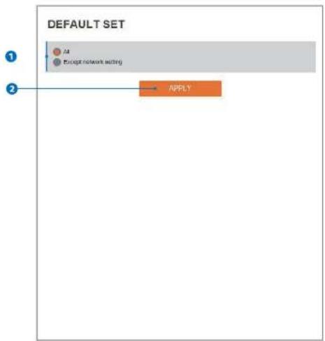
DEFAULT SET ① All Except network setting ② APPLY1 Reset to the factory defaults - Return the setup to the factory default.
All - Reset all Settings to the factory defaults.
Except Network Settings - Except Network related settings, reset all others to the factory default.
2 Click 'Apply' to make above setting effective.
Setup - System Setup
Restart

text_image
The page at 192.168.1.116 says: Do you want to restart the system? OK CancelIf you click the 'RESTART' menu, a message box will be shown to confirm. Click the 'OK' button to restart.
Appendix
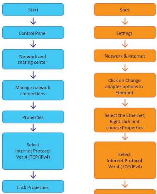
A : Current TCP/IP Settings
If your IP settings are obtained automatically, you could use the MS-DOS prompt (or Command Prompt) to determine your IP address. For information on how to do this, please read the FAQ.
- Windows 7 Users 2. Windows 10 Users

flowchart
graph TD
    A["Start"] --> B["Control Panel"]
    B --> C["Network and sharing center"]
    C --> D["Manage network connections"]
    D --> E["Properties"]
    E --> F["Select Internet Protocol Ver.4 (TCP/IPv4)"]
    G["Start"] --> H["Settings"]
    H --> I["Network & Internet"]
    I --> J["Click on Change adapter options in Ethernet"]
    J --> K["Select the Ethernet, Right click and choose Properties"]
    K --> L["Select Internet Protocol Ver.4 (TCP/IPv4)"]
Appendix -
B: Changing IP address and subnet mask
- Windows 7 Users 2. Windows 10 Users
flowchart
graph TD
    A["Start"] --> B["Control Panel"]
    B --> C["Network and sharing center"]
    C --> D["Manage network connections"]
    D --> E["Properties"]
    E --> F["Select Internet Protocol Ver.4 (TCP/IPv4)"]
    F --> G["Click Properties"]

    H["Start"] --> I["Settings"]
    I --> J["Network & Internet"]
    J --> K["Click on Change adapter options in Ethernet"]
    K --> L["Select the Ethernet, Right click and choose Properties"]
    L --> M["Select Internet Protocol Ver.4 (TCP/IPv4)"]
    M --> N["End"]
Appendix - FAQ
1. My POWER light is not on?
Power is not being supplied to the unit. Please use the power supply shipped with the unit and verify that a power source is active from the attached power outlet used to connect the adapter. You can test this by plugging in any other electrical device and verify its operation. After using the power supply shipped with the product, checking the power source, and reinserting the power connector into the IP Camera, please call our Support Center. The power supply may be defective.
2. My ACTIVE light is not flashing?
Verify the power supply to the unit. Power off the unit and back on again, wait 1 minute, if the ACTIVE light still does not begin to flash, you will have to set the unit to its factory default (THIS WILL DELETE ANY CONFIGURATION AND SET THE UNIT TO THE FACTORY DEFAULTS). Power on the unit and insert the end of a paper clip into the small recessed opening on the back of the unit. Use the clip to press the button located within that opening.
3. My LINK light is not flashing or solid?
Verify the cable connection. 99% of the time the cable's connection to the unit is causing this problem. Try using a different network cable or crossover cable (for PC connection only). Try reinserting the cable, if this still doesn't solve the problem call our Support Center.
4. I can access the video server on my LAN, but not from the Internet.
Verify that your router (if applicable) has port forwarding properly configured. If accessing from our DDNS service, verify correct serial number. Firewall issues may prevent user access.
5. How do I open an MS-DOS or Command Prompt?
Start > (All) Programs > Accessories > Command Prompt
8. How do I "PING" an IP address?
1) Open an MS-DOS (or Command) prompt
2) At the prompt type - "ping xxx.xxx.xxx.xxx" (without the quotes and replace the "x"s with an IP address)
3) Press Enter
9. I'm accessing my video server remotely over the Internet and the video stream is choppy, is this normal?
Yes. The frames per second received remotely are determined by your bandwidth capabilities both at your site where the IP Camera is installed and your remote location. The lower of the two sites will determine how fast your video stream is received. It is recommended to have at least a 256Kb/sec upstream connection from the site where the IP Camera is installed. Lower speeds will operate properly, but provide poor remote performance. The Faster the Internet connection at both ends, the faster the video stream.
10. How do I enable or check VLC on my browser
Internet Explorer
Open Internet Explorer > Tools on the menu bar > Internet Options > Security Tab > Custom Level > Scroll down and verify that you are prompted or have enabled plug-ins to be downloaded and executed. > click OK > restart browser.
Chrome
Open Chrome > Chrome menu settings > Advanced settings > Individual information - content settings > Run automatically
11. How do I reset the unit to factory defaults?
Refer to the previous functions page and ynd the reset button. Power ON the unit and use a paper clip to push the reset button within that setting. You should then see the ACTIVE lightturn
Specifications - Dimension
Unit: Inch (mm)
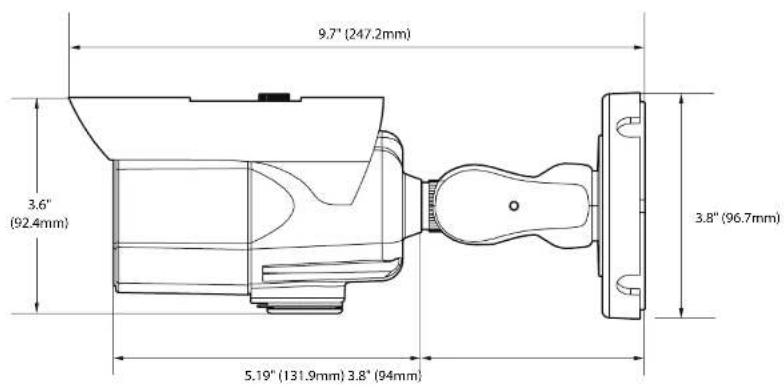
text_image
9.7" (247.2mm) 3.6" (92.4mm) 5.19" (131.9mm) 3.8" (94mm) 3.8" (96.7mm)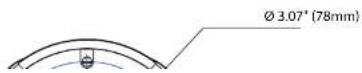
Warranty Information
Digital Watchdog (referred to as "the Warrantor") warrants the Camera against defects in materials or workmanships as follows:
Labor: For the initial five (5) years from the date of original purchase if the camera is determined to be defective, the Warrantor will repair or replace the unit with new or refurbished product at its option, at no charge.
Parts: In addition, the Warrantor will supply replacement parts for the initial two (2) years.
To obtain warranty or out of warranty service, please contact a technical support representative at 1+ (866) 446-3595, Monday through Friday from 9:00AM to 8:00PM EST.
A purchase receipt or other proof of the date of the original purchase is required before warranty service is rendered. This warranty only covers failures due to defects in materials and workmanship which arise during normal use. This warranty does not cover damages which occurs in shipment or failures which are caused by products not supplied by the Warrantor or failures which result from accident, misuse, abuse, neglect, mishandling, misapplication, alteration, modification, faulty installation, setup adjustments, improper antenna, inadequate signal pickup, maladjustments of consumer controls, improper operation, power line surge, improper voltage supply, lightning damage, rental use of the product or service by anyone other than an authorized repair facility or damage that is attributable to acts of God.
Limits & Exclusions
There are no express warranties except as listed above. The Warrantor will not be liable for incidental or consequential damages (including, without limitation, damage to recording media) resulting from the use of these products, or arising out of any breach of the warranty. All express and implied warranties, including the warranties of merchantability and fitness for particular purpose, are limited to the applicable warranty period set forth above.
Some states do not allow the exclusion or limitation of incidental or consequential damages or limitations on how long an implied warranty lasts, so the above exclusions or limitations may not apply to you. This warranty gives you specific legal rights, and you may also have other rights from vary from state to state.
If the problem is not handled to your satisfaction, then write to the following address:
Digital Watchdog, Inc.
ATTN: RMA Department
16220 Bloomfield Ave
Cerritos, CA 90703
Service calls which do not involve defective materials or workmanship as determined by the Warrantor, in its sole discretion, are not covered. Cost of such service calls are the responsibility of the purchaser.
DW DIGITAL WATCHDOG®
Complete Surveillance Solutions
DW° east coast office and warehouse: 5436 W Crenshaw St, Tampa, FL 33634 DW° west coast office and warehouse: 16220 Bloomfield Ave., Cerritos, California, USA 90703 PH: 866-446-3595 | FAX: 813-888-9262
www.Digital-Watchdog.com technicalsupport@dwcc.tv Technical Support PH:
USA & Canada 1+ (866) 446-3595 International 1+ (813) 888-9555
French Canadian 1+ (514) 360-1309