Itona F64 - Laptop LENOVO - Free user manual and instructions
Find the device manual for free Itona F64 LENOVO in PDF.

User questions about Itona F64 LENOVO
0 question about this device. Answer the ones you know or ask your own.
Ask a new question about this device
Download the instructions for your Laptop in PDF format for free! Find your manual Itona F64 - LENOVO and take your electronic device back in hand. On this page are published all the documents necessary for the use of your device. Itona F64 by LENOVO.
USER MANUAL Itona F64 LENOVO
natural_image
Black desktop computer tower with visible ports and ventilation grille (no readable text or symbols)
Itona Fxx Series
Hardware User Guide
Copyright © 2004-2014 VXL Instruments Limited. All Rights Reserved
Information in this document is subject to change without notice and does not represent a commitment on the part of the manufacturer. No part of this guide may be reproduced or transmitted in any form or means, electronic or mechanical, including photocopying and recording, for any purpose, without the express written permission of the manufacturer.
Every effort has been made to make this guide as complete and as accurate as possible, but no warranty or fitness is implied. The authors and the publisher shall have neither responsibility nor liability to any person or entity with respect to loss or damages arising from the use of information contained in this guide. This disclaimer does not apply in countries where such provisions are inconsistent with local law.
Last Updated: September, 2014.
Version: IFS/ UG-36-14.
VXL Instruments Ltd.,
House of Excellence
No. 17, Electronics City,
Hosur Road,
Bangalore—560 100, INDIA
www.vxl.net
Federal Communication Commission (FCC) Statement
This equipment has been tested and found to comply with the limits for a Class B digital device, pursuant to Part 15 of the FCC Rules. These limits are designed to provide reasonable protection against harmful interference in a residential installation. This equipment generates uses and can radiate radio frequency energy and, if not installed and used in accordance with the instructions, may cause harmful interference to radio communications. However there is no guarantee that interference will not occur in a particular installation.
If this equipment does cause harmful interference to radio or television reception, which can be determined by turning the equipment Off and On, the user is encouraged to try to correct the interference by one or more of the following measures:
- Re-orient or relocate the receiving antenna.
- Increase the separation between the equipment and receiver.
- Connect the equipment to an outlet on a circuit different from that to which the receiver is connected.
- Consult the dealer or an experienced radio / television technician for help.
Each Thin Client is equipped with a FCC compliance label that shows only the FCC identification number. The full information of the associated label is as follows:
This device complies with Part 15 of the FCC rules. Operation is subject to the following two conditions:
- This device may not cause harmful interference.
- This device must accept any interference received, including interference that may cause undesired operation.
Battery Information
Batteries, battery packs, and accumulators should not be disposed together with the general household
ENERGY STAR Compliant Product

ENERGY STAR is a joint program of the U.S. Environmental Protection Agency and the U.S. Department of Energy helping us all save money and protect the environment through energy efficient products practices.
Please visit http://www.energystar.gov for detail information on the ENERGY STAR joint program.
Regulatory Certifications


www.tuy.com


RoHS


Table of Contents
Federal Communication Commission (FCC) Statement i
ENERGY STAR Compliant Product ii
Regulatory Certifications iii
1 Introduction 1
About the User Guide 2
Abbreviations and Acronyms 2
Chapters in the Manual 3
2 Installation 5
Unpacking the Unit 5
Preparing to Connect 5
Connecting the Accessories and Power Supply 6
Connecting to the Server 8
LAN Connection through TCP/IP 8
Direct Connection using RS232 cable 8
Dial-In Remote Connection through a Modem 9
3 Specifications 10
Hardware 10
Mechanical 10
Environmental Operating 11
1 Introduction
Thin Clients are essentially terminal devices that connect to multi-user application servers operating under Citrix MetaFrame and Windows 2000/2003/2009 operating systems.
This guide covers installation and hardware details of Itona F series.
text_image
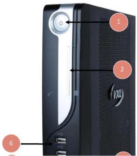
1 2 VXX 6- Power Button
- Smart Card Reader
(Optional). - MIC
- Pedestal
- Audio Line Out
- USB Ports
Features
The product is equipped with a 10/100/1000 Ethernet port that gives an instant connection to a multi-user Windows NT application server. Itona F series has serial, parallel, VGA and DVI-I Ports. USB and PS/2 compatible keyboard/Mouse ports are available for quick setup and use.
Optional Features
The optional features available for Itona F series are listed below:
- Smart Card reader
- Wireless LAN
- 3 ^rd Serial Port
• VESA Mounting Brackets
• Internal Speaker (4 Ohms 1.5W)

Note: The optional features cannot be upgraded in the field. Please contact the reseller or dealer from whom you purchased the product for information about optional features.
About the User Guide
This User Guide provides step by step instructions to install Itona F series hardware. The specifications and troubleshooting steps are also included in this User Guide.
Abbreviations and Acronyms
| Abbreviation | Expansion |
| AC | Alternating Current |
| DC | Direct Current |
| LAN | Local Area Network |
Chapters in the Manual
| Chapter No | Chapter Name | Description |
| 1 | Introduction | Contains an overview of the product, information about this guide and abbreviations used in this guide. |
| 2 | Installation | Contains the procedure to setup the hardware. |
| 3 | Specifications | Contains hardware, mechanical, electrical, interface and operating environment specifications |
| 4 | Troubleshooting | Contains solutions to problems that you may encounter while using the product. |
| — | Appendix | Contains detailed specifications for connectors and cables used with the product. |
Table 2: List of Chapters

Warning
- Any changes or modifications not expressly approved by the party responsible for compliance could void the user's authority to operate this equipment.
- There is no user serviceable part inside. Do not open enclosure, hazardous voltages present inside equipment. Do not disassemble the equipment as this can nullify your warranty.
• This equipment must be earthed. - The AC socket outlet shall be installed near the equipment and shall be easily accessible.
• Sound Power Level is less than 60dB (A) when measured according to ISO 7779
- Do not operate this equipment outside specified temperature limits.
2 Installation
This chapter describes hardware installation of the product.
To install the Itona F series hardware, do the following steps:
- Unpack the unit.
- Prepare to connect.
- Connect the accessories and power.
- Connect to the server
Each step is explained in detail in this chapter.
Unpacking the Unit
Unpack the unit taking care not to drop the product whilst removing from the packaging.
The carton in which the product was shipped to you contains the following:
- Itona F series Thin Client
• AC-DC power adapter 12V /5A - Pedestal Set
• Power cord (optional)
• DVI to VGA cable (optional) - Mouse (optional)
• VESA Mounting bracket (optional)
• Hardware Installation Guide
• Table or desk of suitable size.
- Fix the pedestals at the bottom of the thin client.
- Place the product on the table in a location that provides quick and easy access to the power Inlet plug to shutdown the power in emergencies.
- Ensure a minimum space of 2 inches (5 cm) on all sides of the unit for efficient convection cooling.
Connecting the Accessories and Power Supply
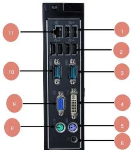
The various connectors available on the rear panel of the client are shown in Figure 2.
text_image
11 10 9 8 1 2 3 4 5 61.2 x USB ports
2.4×USB ports
3. 1 x Serial Port
4. DVI port
5. PS/2 KBD
6. DC power in 12V/5A
7. Serial port (Optional)
8. PS/2 mouse port
9. VGA port
10. COM port 2
11. Ethernet port
| Connectors | Connector Symbol |
| VGA port | [80CT] |
| DVI-I port | [50TY] |
| USB port |  |
| Audio output (LINE OUT) port |  |
| Microphone input port |  |
| PS/2 Keyboard port |  |
| PS/2 Mouse port |  |
| COM port | [C8TB] |
| RJ45 Ethernet port |  |
Table 3: Connector Symbols

Note: Before connecting any cables, ensure that the power cable is unplugged from the unit.

Caution: Ensure that COM1, COM2, COM3, VGA, and DVI Ports are adequately fastened with the screws provided with the cables.
Connecting to the Server
The Thin Client can be physically connected to the server/network in three ways:
• LAN connection through TCP/IP.
- Direct connection through RS232.
• Dial-in remote connection through a modem.
LAN Connection through TCP/IP
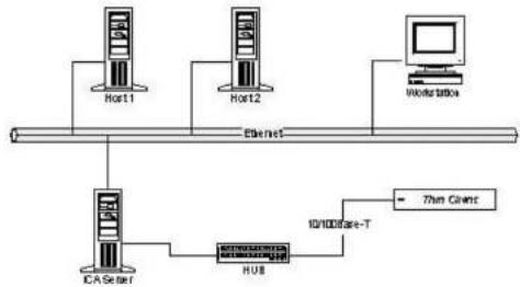
To connect client to LAN through TCP/IP:
- Connect one end of a 10/100/1000 cable to the LAN port of the client.
- Connect the other end to a LAN hub as shown in Figure 3.
flowchart
graph TD
    A["Host1"] --> B["ICAS Server"]
    C["Host2"] --> D["HUB"]
    E["Workstation"] --> F["700 Client"]
    B --> G["10/100Base-T"]
    D --> G
    F --> G
Figure 3: LAN Connection through TCP/IP
- Press the power button to turn on the Itona F series. The front panel LED lights up and the client
Dial-In Remote Connection through a Modem
To connect client by dial-in remote connection through a modem:
- Connect one end of an RS232 straight cable to a serial port of the client.
- Connect the other end to a modem as shown in Figure 5.

flowchart
graph LR
    A["Server"] --> B["MODM PORT"]
    B --> C["MODem"]
    C --> D["PORT"]
    D --> E["MODem"]
    E --> F["MODM PORT"]
    F --> G["Data Client"]
    H["RECEO STRAIGHT"] --> I["COM PORT"]
    J["RECEO STRAIGHT"] --> K["COM PORT"]
Figure 5: Dial-In Remote Connection through Modem
- Press the power button to turn on the Itona F series. The front panel LED lights up and the client boots up with a beep sound. The Connection Manager screen appears.

Note: To configure the client, refer to the Software User's Guide.
3 Specifications
Hardware
| Processor | VIA Nano U3300 1.2GHz |
| Chipset | VIA VX900 |
| VGA Memory | Shared Video Memory 128MB min 512 max |
| Flash | SATA Min support 512MB, 4GB Max |
| RAM | DDRIII SODIMM 1066MHz Min Support 1GB |
| Network | 10/100/1000 Mbps |
| Maximum Display Resolution | VGA -2048x1536 @75Hz, 16/32 bits max.DVI-I - 1920 X 1200 @60Hz 16/32 bits max. |
| Power Supply | External 12V / 5.0A Adapter |
| Smart Card reader | Optional |
| Wireless LAN | Optional |
| 3^rd COM Port | Optional |
Environmental Operating
Operating temperature + 5°C to +40°C (Vertical position)
Storage temperature - 20°C to +65°C
Humidity 20% to 80% RH non-condensing
Electrical – External Power Adapter
Line Voltage 100V to 240V AC
Line Frequency 50 / 60 Hz
Power Inlet 1.5A, 3-pin power plug (IEC 320)
Power Output 12 V / 5A max
4 Troubleshooting
This chapter contains solutions for problems you may encounter while using the product.
Problem
Solution
The power-LED on front panel does not glow when the client is turned on.
√ Ensure that the power cord is plugged into an AC outlet.
There is no display, though the power-indicating LED glows.
√ Check the fuse in the power-plug, if available.
The mouse (or keyboard) does not work when the client is switched on.
√ Ensure that the video cable is properly connected.
√ Ensure that the mouse (or keyboard) is plugged into the correct USB port on the rear panel.
Appendix
Connectors
The following section provides pin details for various connectors on the rear panel of the client.
COM Port
9-pin D-type male connector. RS232C compatible, operating at 115.2K baud maximum.
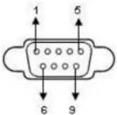
| Pin | Signal | Description |
| 1 | DCD | Data Carrier Detect |
| 2 | RxD | Receive Data |
| 3 | TxD | Transmit Data |
| 4 | DTR | Data Terminal Ready |
| 5 | GND | Signal Ground |
| 6 | DSR | Data Set Ready |
| 7 | RTS | Request To Send |
10/100/1000 LAN Port
RJ-45 modular 8-pin jack. 10/100/1000 Mbps.

Pin Signal
1 TxD+
2 TxD-
3 RxD+
6 RxD
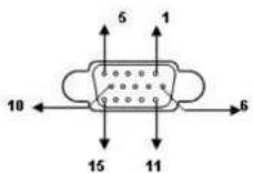
Video Port
15-pin D-type female connector.
DVI-I Port
Pin C1 to C5 carry the analogue signal.24+ 5 pin DVI Connector.
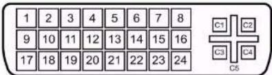
text_image
1 2 3 4 5 6 7 8 9 10 11 12 13 14 15 16 17 18 19 20 21 22 23 24 C1 C2 C3 C4 C5| Pin | Signal | Pin | Signal | Pin | Signal |
| 1 | TMDS Data 2- | 11 | TMDS Data 1/3 Shield | 21 | TMDS Data 5+ |
| 2 | TMDS Data 2+ | 12 | TMDS Data 3- | 22 | TMDS Clock Shield |
| 3 | TMDS Data 2/4 Shield | 13 | TMDS Data 3+ | 23 | TMDS Clock + |
| 4 | TMDS Data 4- | 14 | +5 V Power | 24 | TMDS Clock - |
| 5 | TMDS Data 4+ | 15 | Ground(for+5V) | C1 | Analog Red |
| 6 | DDC Clock | 16 | Hot Plug Detect | C2 | Analog Green |
| 7 | DDC Data | 17 | TMDS Data 0- | C3 | Analog Blue |
| 8 | Analog Vertical Sync | 18 | TMDS Data 0+ | C4 | Analog Horizontal Sync |
| 9 | TMDS Data 1- | 19 | TMDS Data 0/5 Shield | C5 | Analog Ground (analog R, G & B return) |
| 10 | TMDS Data 1+ | 20 | TMDS Data 5- |
PS/2 Mouse / Keyboard Port
Mouse / Keyboard connector
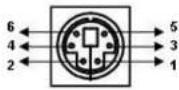
| Pin | Signal | Pin | Signal |
| 1 | Mouse / KBD data | 4 | VCC |
| 2 | NC | 5 | Mouse / KBD Clock |
| 3 | GND | 6 | NC |
Audio Port
Line Out/Mic ports
Standard audio jacks.
USB Port 2.0
4-pin series-A receptacle. 4\~5 ports depending on the model.
Revision History
| Version | Change Details | Authors/ Reviewers | Date |
| IFS/ UG-36-14 | Changed the User guide title to Fxx, changed the hyperlink address under product safety and online support. Updated certification logo images. | Sharath, Sai priya | 05 Sep 2014 |