DS-2XM6222G0-IM/ND - Security Camera Hikvision - Free user manual and instructions
Find the device manual for free DS-2XM6222G0-IM/ND Hikvision in PDF.

User questions about DS-2XM6222G0-IM/ND Hikvision
0 question about this device. Answer the ones you know or ask your own.
Ask a new question about this device
Download the instructions for your Security Camera in PDF format for free! Find your manual DS-2XM6222G0-IM/ND - Hikvision and take your electronic device back in hand. On this page are published all the documents necessary for the use of your device. DS-2XM6222G0-IM/ND by Hikvision.
USER MANUAL DS-2XM6222G0-IM/ND Hikvision
Initiatives on the Use of Video Products
Thank you for choosing Hikvision products.
Technology affects every aspect of our life. As a high-tech company, we are increasingly aware of the role technology plays in improving business efficiency and quality of life, but at the same time, the potential harm of its improper usage. For example, video products are capable of recording real, complete and clear images. This provides a high value in retrospect and preserving real-time facts. However, it may also result in the infringement of a third party's legitimate rights and interests if improper distribution, use and/or processing of video data takes place. With the philosophy of "Technology for the Good", Hikvision requests that every end user of video technology and video products shall comply with all the applicable laws and regulations, as well as ethical customs, aiming to jointly create a better community.
Please read the following initiatives carefully:
- Everyone has a reasonable expectation of privacy, and the installation of video products should not be in conflict with this reasonable expectation. Therefore, a warning notice shall be given in a reasonable and effective manner and clarify the monitoring range, when installing video products in public areas. For non-public areas, a third party's rights and interests shall be evaluated when installing video products, including but not limited to, installing video products only after obtaining the consent of the stakeholders, and not installing highly-invisible video products.
- The purpose of video products is to record real activities within a specific time and
Therefore, every end user and data controller, shall undertake all reasonable and necessary measures to ensure data security and avoid data leakage, improper disclosure and improper use, including but not limited to, setting up access control, selecting a suitable network environment (the Internet or Intranet) where video products are connected, establishing and constantly optimizing network security.
- Video products have made great contributions to the improvement of social security around the world, and we believe that these products will also play an active role in more aspects of social life. Any abuse of video products in violation of human rights or leading to illegal activities are contrary to the original intent of technological innovation and product development. Therefore, each user shall establish an evaluation and tracking mechanism of their product application to ensure that every product is used in a proper and reasonable manner and with good faith.
User Manual
© 2021 Hangzhou Hikvision Digital Technology Co., Ltd. All rights reserved.
This Manual is the property of Hangzhou Hikvision Digital Technology Co., Ltd. or its affiliates (hereinafter referred to as "Hikvision"), and it cannot be reproduced, changed, translated, or distributed, partially or wholly, by any means, without the prior written permission of Hikvision. Unless otherwise expressly stated herein, Hikvision does not make any warranties, guarantees or representations, express or implied, regarding to the Manual, any information contained herein.
About this Manual
The Manual includes instructions for using and managing the Product. Pictures, charts, images and all other information hereinafter are for description and explanation only. The information contained in the Manual is subject to change, without notice, due to firmware updates or other reasons. Please find the latest version of this Manual at the Hikvision website (http://www.hikvision.com). Please use this Manual with the guidance and assistance of professionals trained in supporting the Product.
THE PRODUCT DESCRIBED, WITH ITS HARDWARE, SOFTWARE AND FIRMWARE, ARE PROVIDED "AS IS" AND "WITH ALL FAULTS AND ERRORS". HIKVISION MAKES NO WARRANTIES, EXPRESS OR IMPLIED, INCLUDING WITHOUT LIMITATION, MERCHANTABILITY, SATISFACTORY QUALITY, OR FITNESS FOR A PARTICULAR PURPOSE. THE USE OF THE PRODUCT BY YOU IS AT YOUR OWN RISK. IN NO EVENT WILL HIKVISION BE LIABLE TO YOU FOR ANY SPECIAL, CONSEQUENTIAL, INCIDENTAL, OR INDIRECT DAMAGES, INCLUDING, AMONG OTHERS, DAMAGES FOR LOSS OF BUSINESS PROFITS, BUSINESS INTERRUPTION, OR LOSS OF DATA, CORRUPTION OF SYSTEMS, OR LOSS OF DOCUMENTATION, WHETHER BASED ON BREACH OF CONTRACT, TORT (INCLUDING NEGLIGENCE), PRODUCT LIABILITY, OR OTHERWISE, IN CONNECTION WITH THE USE OF THE PRODUCT, EVEN IF HIKVISION HAS BEEN ADVISED OF THE POSSIBILITY OF SUCH DAMAGES OR LOSS.
YOU ACKNOWLEDGE THAT THE NATURE OF INTERNET PROVIDES FOR INHERENT SECURITY RISKS, AND HIKVISION SHALL NOT TAKE ANY RESPONSIBILITIES FOR ABNORMAL OPERATION, PRIVACY LEAKAGE OR OTHER DAMAGES RESULTING FROM CYBER-ATTACK, HACKER ATTACK, VIRUS INSPECTION, OR OTHER INTERNET SECURITY RISKS; HOWEVER, HIKVISION WILL PROVIDE TIMELY TECHNICAL SUPPORT IF REQUIRED.
Notice:
If camera fails to synchronize local time with that of the network, you need to set up camera time manually. Visit the camera and enter system setting interface for time setting.
LAW, THE LATER PREVAILS. Safety Instruction
These instructions are intended to ensure that the user can use the product correctly to avoid danger or property loss.
The precaution measure is divided into 'Warnings' and 'Cautions':
Warnings: Serious injury or death may be caused if any of these warnings are neglected.
Cautions: Injury or equipment damage may be caused if any of these cautions are neglected.

Warnings Follow these safeguards to prevent serious injury or death.

Cautions Follow these precautions to prevent potential injury or material damage.
- Please make sure that the ceiling can support more than 50(N) Newton gravities if the camera is fixed to the ceiling.
- If the product does not work properly, please contact your dealer or the nearest service center. Never attempt to disassemble the camera yourself. (We shall not assume any responsibility for problems caused by unauthorized repair or maintenance.)

Cautions:
● Make sure the power supply voltage is correct before using the camera.
- Do not drop the camera or subject it to physical shock.
- Do not touch sensor modules with fingers. If cleaning is necessary, use a clean cloth with a bit of ethanol and wipe it gently. If the camera will not be used for an extended period of time, put on the lens cap to protect the sensor from dirt.
- Do not aim the camera lens at the strong light such as sun or incandescent lamp. The strong light can cause fatal damage to the camera.
- The sensor may be burned out by a laser beam, so when any laser equipment is being used, make sure that the surface of the sensor not be exposed to the laser beam.
precautions to prevent IR reflection:
- Dust or grease on the dome cover will cause IR reflection. Please do not remove the dome cover film until the installation is finished. If there is dust or grease on the dome cover, clean the dome cover with clean soft cloth and isopropyl alcohol.
- Make certain the installation location does not have reflective surfaces of objects too close to the camera. The IR light from the camera may reflect back into the lens causing reflection.
- The foam ring around the lens must be seated flush against the inner surface of the bubble to isolate the lens from the IR LEDS. Fasten the dome cover to camera body so that the foam ring and the dome cover are attached seamlessly.
Table of Contents
Chapter 1 System Requirement .... 12
Chapter 2 Network Connection .... 13
2.1 Setting the Network Camera over the LAN.... 13
2.1.1 Wiring over the LAN....13
2.1.2 Activating the Camera 14
2.1.3 (Optional) Setting Security Question 21
2.2 Setting the Network Camera over the WAN 21
2.2.1 Static IP Connection....21
2.2.2 Dynamic IP Connection....22
Chapter 3 Access to the Network Camera....25
3.1 Accessing by Web Browsers....25
3.2 Accessing by Client Software 26
Chapter 4 Wi-Fi Settings.... 28
4.1 Configure Wi-Fi Connection in Manage and Ad-hoc Modes.... 28
4.2 Easy Wi-Fi Connection with WPS function.... 33
4.3 IP Property Settings for Wireless Network Connection.... 35
Chapter 5 Live View.... 37
5.1 Live View Page.... 37
5.2 Starting Live View.... 38
5.2 Recording and Capturing Pictures Manually 20
Network Camera User Manual
6.3 Maintenance 52
6.3.1 Upgrade & Maintenance 52
6.3.2 Log 53
6.3.3 System Service 54
6.4 Security Settings....55
6.4.1 Authentication....55
6.4.2 IP Address Filter 55
6.4.3 Security Service....57
6.5 User Management....58
6.5.1 User Management 58
6.5.2 Security Question 60
6.5.3 Online Users....61
Chapter 7 Network Settings 62
7.1 Configure Basic Settings....62
7.1.1 Configure TCP/IP Settings 62
7.1.2 Configure DDNS Settings 64
7.1.3 Configure PPPoE Settings....66
7.1.4 Configure Port Settings....66
7.1.5 Configure NAT (Network Address Translation) Settings....68
7.2 Configure Advanced Settings 69
7.2.1 Configure SNMP Settings....69
7.2.2 Configure FTP Settings....72
7.2.3 Configure Email Settings....74
7.2.4 Platform Access 76
7.2.5 Wireless Dial 77
7.3.6 HTTP: 0.41...
Network Camera User Manual
Chapter 9 Image Settings....98
9.1 Configure Display Settings 98
9.1.1 Day/Night Auto-Switch 98
9.1.2 Day/Night Scheduled-Switch 102
9.2 Configure OSD Settings....103
9.3 Configure Privacy Mask....105
9.4 Configure Picture Overlay....106
Chapter 10 Event Settings....107
10.1 Basic Events....107
10.1.1 Configure Motion Detection....107
10.1.2 Configure Video Tampering Alarm....113
10.1.3 Configure Alarm Input 114
10.1.4 Configure Alarm Output 116
10.1.5 Handling Exception 117
10.1.6 Configure Other Alarm 117
10.2 Smart Events....120
10.2.1 Configure Audio Exception Detection....121
10.2.2 Configure Defocus Detection....122
10.2.3 Configure Scene Change Detection 123
10.2.4 Configure Object detection 124
10.2.5 Configure Intrusion Detection 125
10.2.6 Configure Line Crossing Detection....127
10.2.7 Configure Region Entrance Detection....130
10.2.8 Configure Region Exiting Detection 132
10.2.9 Configure Unattended Baggage Detection 134
Network Camera User Manual
11.5 Configure Lite Storage ....170
Chapter 12 Playback....172
Chapter 13 Picture....174
Chapter 14 Application....176
14.1 Face Capture Statistics....176
14.2 People Counting Statistics ....177
14.3 Heat Map Statistics....177
14.4 Counting Statistics....179
14.5 Queue Management Statistics....179
14.5.1 Queuing-Up Time Analysis....180
14.5.2 Queue Status Analysis 181
14.5.3 Raw Data....182
Appendix 183
Appendix 1 SADP Software Introduction....183
Appendix 2 Port Mapping ....186
Appendix 3 ....188
Device Communication Matrix....188
Device Command....188
Chapter 1 System Requirement
Operating System
Microsoft Windows XP SP1 and above version
CPU
2.0 GHz or higher
RAM
1G or higher
Display
1024×768 resolution or higher
Web Browser
For camera that supports plug-in free live view
Internet Explorer 8 – 11, Mozilla Firefox 30.0 and above version and Google
Chrome 41.0 and above version.
Note:
For Google Chrome 45 and its above version or Mozilla Firefox 52 and its above
version which are plug-in free, Picture and Playback functions are hidden.
To use mentioned functions via web browser, change to their lower version, or
Chapter 2 Network Connection
Note:
- You shall acknowledge that the use of the product with Internet access might be under network security risks. For avoidance of any network attacks and information leakage, please strengthen your own protection. If the product does not work properly, please contact with your dealer or the nearest service center.
- To ensure the network security of the network camera, we recommend you to have the network camera assessed and maintained termly. You can contact us if you need such service.
Before you start:
- If you want to set the network camera via a LAN (Local Area Network), please refer to Section 2.1 Setting the Network Camera over the LAN.
- If you want to set the network camera via a WAN (Wide Area Network), please refer to Section 2.2 Setting the Network Camera over the WAN.
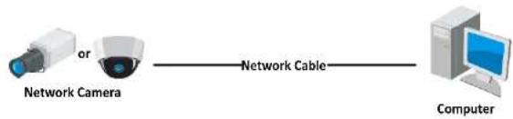
2.1 Setting the Network Camera over the LAN
Purpose:
Network Camera User Manual
computer with a network cable as shown in Figure 2-1.
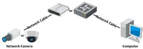
- Refer to the Figure 2-2 to set network camera over the LAN via a switch or a router.
flowchart
graph LR
    A["or"] --> B["Network Cable"]
    B --> C["Computer"]
Figure 2-1 Connecting Directly
flowchart
graph LR
    A["Network Camera"] -->|or| B["Computer"]
    B -->|or| C["Network Cable"]
    C --> D["Computer"]
Figure 2-2 Connecting via a Switch or a Router
2.1.2 Activating the Camera
You are required to activate the camera first by setting a strong password for it
Network Camera User Manual
- For the camera enables the DHCP by default, you need to use the SADP software to search the IP address.

text_image
Activewear User Name Password admin ✓ valid password to range (0, 10). Your Sub-case a combination of numbers, in millions, approximate and/or other/ character for your password with at fractiths kinds of them combined Confirm OKFigure 2-3 Activation via Web Browser
- Create and input a password into the password field.
A password with user name in it is not allowed.

STRONG PASSWORD RECOMMENDED-We highly recommend you create a strong password of your own choosing (using a minimum of 8 characters, including at least three of the following categories: upper case letters, lower case letters, numbers, and special characters) in order to increase the security
Steps:
- Run the SADP software to search the online devices.
- Check the device status from the device list, and select the inactive device.

text_image
Test result of active devices ✓ 007 Inactive 192.168.1.64 Select inactive device. Input and confirm password.Figure 2-4 SADP Interface
Note:
The SADP software supports activating the camera in batch. Refer to the user manual of SADP software for details.
- Create and input the password in the password field, and confirm the password. A password with user name in it is not allowed.
Network Camera User Manual
- Click Activate to start activation.
You can check whether the activation is completed on the popup window. If activation failed, please make sure that the password meets the requirement and try again.
- Change the device IP address to the same subnet with your computer by either modifying the IP address manually or checking the checkbox of Enable DHCP.

text_image
Modify Network Parameters Enable DHCP Enable Hic Connect Device Serial No: 001000000000000000000000000000000000000000000000000000000000000000000000000000000000000000000 IP Address: 192.168.1.54 Port: 3893 Submit Mask: 255.255.255.0 Gateway: 192.168.1.1 IPv3 Address: = IPv3 Gateway: = IPv6 Prefix Length: 6 HTTP Port: 80 Security Verification Admin Password:Network Camera User Manual
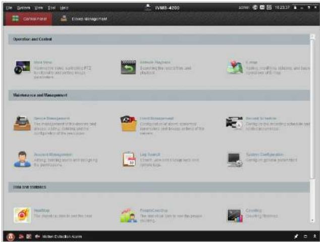
software according to the prompts. Follow the steps to activate the camera.
Steps:
- Run the client software and the control panel of the software pops up, as shown in the figure below.
text_image
IVM8-4200 Operation and Control Initial Time Information video, monitoring PTZ functionally and working images operations Remote Graphics Scanning the security and platforms E-mail Adding meaningful details and basic information of E-mail Maintenance and Management Service Management The implementation of the operations and process planning, scheduling and his management of the operations Event Management Configuration of above approved customers and services, sharing of the operations Recent Service Configing the following specific tasks (e.g. Edit Operations) Account Management Adding trading tools and managing the processes. Log Search Content, access to storage keys and software keys. System Configuration Configing the following procedures Data and Statistics Headups The platform can use to test the data Create Cooking The start of the time to see the person building Creating Creating SoftwareFigure 2-6 Control Panel
Network Camera User Manual
text_image
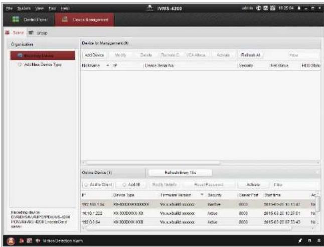
IVM5-4200 Add Device Type Add New Device Type Device for Management (9) Add Device No. 36 Delete Runuate C VCA Africa Activate Refresh At False PickName IP Device Serial No. Security Net Status HDD Serial Online Device (3) Refresh Even 10s Add User Add All Modify Tools Reset Password Activate Fits IP Device Type Hardware Version Security Server Port Start Time 192.163.1.94 KK-XXXXXXX-XXXXXX Vcc:build Service Active 8003 2015-03-25 10:13:47 No 19.19.1.222 KK-XXXXXXX-XX Vcc:build Service Active 8009 2015-03-25 10:27:51 No 192.0.9.94 KK-XXXXXX-XXX Vcc:build Service Active 8003 2015-03-25 07:51:43 No Encoding device C:\RVD\G\C\RP\C\PDC\A\5-0200 PC\VA\N\B-4208\Encode\Cent systemFigure 2-7 Device Management Interface
- Check the device status from the device list, and select an inactive device.
- Click the Activate button to pop up the Activation interface.
- Create a password and input the password in the password field, and confirm the password.
Network Camera User Manual

text_image
Activation User Name: admin Password: ••••••••• Strong Valid password range [8-16]. You can use a combination of numbers, lowercase, uppercase and special character for your password with at least two kinds of them contained. Confirm New Password: ••••••••• Ok CancelFigure 2-8 Activation Interface (Client Software)
- Click OK button to start activation.
- Click the Modify Netinfo button to pop up the Network Parameter Modification interface, as shown in the figure below.
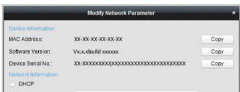
text_image
Modify Network Parameter Device Information: MAC Address: XX-XX-XX-XX-XX Software Version: Vx.x.build xxxxxx Device Serial No.: XX-XXXXXXXXXXXXXXXXXXXXXXXXXXXXX Network Information DHCP2.1.3 (Optional) Setting Security Question
Security question is used to reset the admin password when admin user forgets the password.
Admin user can follow the pop-up window to complete security question settings during camera activation. Or, admin user can go to User Management interface to set up the function.
2.2 Setting the Network Camera over the WAN
Purpose:
This section explains how to connect the network camera to the WAN with a static IP or a dynamic IP.
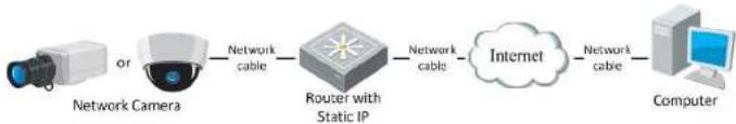
2.2.1 Static IP Connection
Before you start:
Please apply a static IP from an ISP (Internet Service Provider). With the static IP address, you can connect the network camera via a router or connect it to the WAN
Network Camera User Manual
- Visit the network camera through a web browser or the client software over the internet.
flowchart
graph LR
    A["or"] --> B["Network Camera"]
    B --> C["Network cable"]
    C --> D["Router with Static IP"]
    D --> E["Network cable"]
    E --> F["Internet"]
    F --> G["Network cable"]
    G --> H["Computer"]
Figure 2-10 Accessing the Camera through Router with Static IP
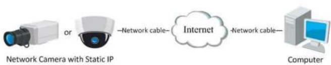
- Connecting the network camera with static IP directly
You can also save the static IP in the camera and directly connect it to the internet without using a router. Refer to Section 2.1.2 for detailed IP address configuration of the network camera.
flowchart
graph LR
    A["or"] --> B["Network Camera with Static IP"]
    B --> C["Internet"]
    C --> D["Computer"]
    style A fill:#f9f,stroke:#333
    style B fill:#ccf,stroke:#333
    style C fill:#cfc,stroke:#333
    style D fill:#fcc,stroke:#333
Figure 2-11 Accessing the Camera with Static IP Directly
2.2.2 Dynamic IP Connection
with port mapping.
Note: Refer to Appendix 2 for detailed information about port mapping.
- Apply a domain name from a domain name provider.
- Configure the DDNS settings in the setting interface of the router.
- Visit the camera via the applied domain name.
- Connecting the network camera via a modem
Purpose:
This camera supports the PPPoE auto dial-up function. The camera gets a public IP address by ADSL dial-up after the camera is connected to a modem. You need to configure the PPPoE parameters of the network camera. Refer to Section 7.1.3 Configure PPPoE Settings for detailed configuration.

flowchart
graph LR
    A["Network Camera"] -->|Network cable| B["Modem"]
    B -->|Network cable| C["Internet"]
    C -->|Network cable| D["Computer"]
Figure 2-12 Accessing the Camera with Dynamic IP
Note: The obtained IP address is dynamically assigned via PPPoE, so the IP address always changes after rebooting the camera. To solve the inconvenience of the dynamic IP, you need to get a domain name from the DDNS provider (E.g.
- Apply a domain name from a domain name provider.
- Configure the DDNS settings in the DDNS Settings interface of the network camera. Refer to Section 7.1.2 Configure DDNS Settings for detailed configuration.
- Visit the camera via the applied domain name.
Chapter 3 Access to the Network Camera
3.1 Accessing by Web Browsers
Note:
For certain camera models, HTTPS is enabled by default and the camera creates an unsigned certificate automatically. When you access to the camera the first time, the web browser prompts a notification about the certificate issue.
To cancel the notification, install a signed-certificate to the camera. For detailed operation, see 7.2.6 HTTPS Settings.
Steps:
-
Open the web browser.
-
In the browser address bar, input the IP address of the network camera, and press the Enter key to enter the login interface.
Note:
The default IP address is 192.168.1.64. You are recommended to change the IP
Network Camera User Manual

text_image
Digital camera app login interface with input fields and city skyline backgroundFigure 3-1 Login Interface
-
Click Login.
-
(Optional) Install the plug-in before viewing the live video and operating the camera. Follow the installation prompts to install the plug-in
Note:
For camera that supports plug-in free live view, if you are using Google Chrome 45 and its above version or Mozilla Firefox 52 and its above version, plug-in installation is not required. But Picture and Playback functions are hidden. To use mentioned function via web browser, change to their lower version, or change to Internet Explorer 8.0 and above version.
3.2 Accessing by Client Software
Network Camera User Manual

text_image
Control Panel Device Management Operation and Control Start your Working the video, networking V12 Functionally and working on system tools. Enterprise Playbox Switching the installed video and session. Lines Aligned, making, holding and removing system tools like Maintenance and Management Device Management The management of the video and process editing, opening and the configuration of the video System Management Adding, building services and organizing the projector. System Configurations Config general perception Data and statistics Healthcare The database is to have the link. Programs This particular only can use the people planning. Services Creating StatisticsFigure 3-2 iVMS-4200 Control Panel

text_image
File System New Test Help FMS-4208 Control Plan Custom Management Event Management Show User Remove Playback View List 1-Screen 2-Screen 3-Screen 4-Screen 5-ScreenChapter 4 Wi-Fi Settings
Purpose:
By connecting to the wireless network, you don't need to use cable of any kind for network connection, which is very convenient for the actual monitoring application.
Note: This chapter is only applicable for the cameras with the built-in Wi-Fi module.
4.1 Configure Wi-Fi Connection in Manage and Ad-hoc Modes
Purpose:
Two connection modes are supported. Choose a mode as desired and perform the steps to configure the Wi-Fi.
Wireless Connection in Manage Mode
Steps:
- Enter the Wi-Fi configuration interface.
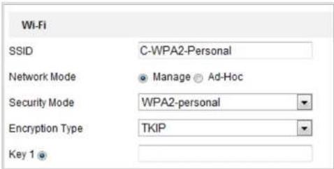
Configuration> Network> Advanced Settings> Wi-Fi - Click Search to search the online wireless connections.
Figure 4-1 Wi-Fi List
- Click to choose a wireless connection on the list.
text_image
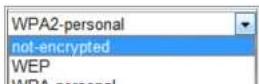
Wi-Fi SSID C-WPA2-Personal Network Mode Manage Ad-Hoc Security Mode WPA2-personal Encryption Type TekIP Key 1Figure 4-2 Wi-Fi Setting- Manage Mode
- Check the radio button to select the Network mode as Manage, and the Security mode of the network is automatically shown when you select the wireless network, please don't change it manually.
Note: These parameters are exactly identical with those of the router.
- Enter the key to connect the wireless network. The key should be that of the wireless network connection you set on the router.
Wireless Connection in Ad-hoc Mode
If you choose the Ad-hoc mode, you don't need to connect the wireless camera via a
Network Camera User Manual
Figure 4-3 Wi-Fi Setting- Ad-hoc
- Customize a SSID for the camera.
- Choose the Security Mode of the wireless connection.
- Enable the wireless connection function for your PC.
- On the PC side, search the network and you can see the SSID of the camera
listed.

text_image
camera6467wifi belkin54g Tenda_0A0698 yourPC HenryHu APPLE Peter_Ma Open Network and Sharing CenterFigure 4-4 Ad-hoc Connection Point
- Choose the SSID and connect.
Security Mode Description:
Network Camera User Manual

text_image
Security Mode Authentication Open Shared Key Length 64bit 128bit Key Type HEX ASCII Key 1 Key 2 Key 3 Key 4Figure 4-6 WEP Mode
- Authentication - Select Open or Shared Key System Authentication, depending on the method used by your access point. Not all access points have this option, in which case they probably use Open System, which is sometimes known as SSID Authentication.
- Key length - This sets the length of the key used for the wireless encryption, 64 or 128 bit. The encryption key length can sometimes be shown as 40/64 and 104/128.
- Key type - The key types available depend on the access point being used. The following options are available:
Network Camera User Manual
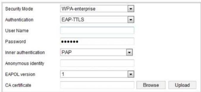
Choose the type of client/server authentication being used by the access point; EAP-TLS or EAP-PEAP.
EAP-TLS
text_image
Security Mode WPA-enterprise Authentication EAP-TTLS User Name Password Inner authentication PAP Anonymous identity EAPOL version 1 CA certificate Browse UploadFigure 4-8 EAP-TLS
- Identity - Enter the user ID to present to the network.
- Private key password – Enter the password for your user ID.
- EAPOL version - Select the version used (1 or 2) in your access point.
- CA Certificates - Upload a CA certificate to present to the access point for authentication.
FAP-PFAP·
strongly recommend the use of strong passwords for all functions and network devices. The password should be something of your own choosing (using a minimum of 8 characters, including at least three of the following categories: upper case letters, lower case letters, numbers and special characters) in order to increase the security of your product.
- Proper configuration of all passwords and other security settings is the responsibility of the installer and/or end-user.
4.2 Easy Wi-Fi Connection with WPS function
Purpose:
The setting of the wireless network connection is never easy. To avoid the complex setting of the wireless connection you can enable the WPS function.
WPS (Wi-Fi Protected Setup) refers to the easy configuration of the encrypted connection between the device and the wireless router. The WPS makes it easy to add new devices to an existing network without entering long passphrases. There are two modes of the WPS connection, the PBC mode and the PIN mode.
Note: If you enable the WPS function, you do not need to configure the parameters such as the encryption type and you don't need to know the key of the wireless
PBC Mode:
PBC refers to the Push-Button-Configuration, in which the user simply has to push a button, either an actual or virtual one (as the button on the
configuration interface of the IE browser), on both the Access Point (and a registrar of the network) and the new wireless client device.
- Check the checkbox of ☑ Enable WPS to enable WPS.
- Choose the connection mode as PBC.

Note: Support of this mode is mandatory for both the Access Points and the connecting devices.
- Check on the Wi-Fi router to see if there is a WPS button. If yes push the button and you can see the indicator near the button start flashing, which means the WPS function of the router is enabled. For detailed operation, please see the user guide of the router.
- Push the WPS button to enable the function on the camera.
If there is not a WPS button on the camera, you can also click the virtual button to enable the PBC function on the web interface.
Network Camera User Manual

text_image
WPS Enable WPS PIN Code 12345678 Generate PBC connection Connect Use router PIN code Connect SSID C-WPA2-Personal Router PIN codeFigure 4-10 Use PIN Code
If the PIN code is generated from the router side, you should enter the PIN code you get from the router side in the Router PIN code field.
3. Click Connect.
Or
You can generate the PIN code on the camera side. And the expired time for the PIN code is 120 seconds.
- Click Generate.

- Enter the code to the router, in the example, enter 48167581 to the router.
Network Camera User Manual
text_image
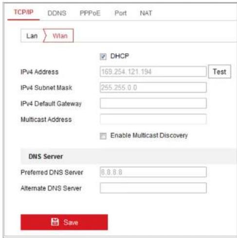
TCP/IP DDNS PPPoE Port NAT Lan Wlan DHCP IPv4 Address 169.254.121.194 Test IPv4 Subnet Mask 255.255.0.0 IPv4 Default Gateway Multicast Address Enable Multicast Discovery DNS Server Preferred DNS Server 8.8.8.8 Alternate DNS Server SaveFigure 4-11 Setting WLAN Parameters
- Customize the IPv4 address, the IPv4 Subnet Mask and the Default Gateway.
The setting procedure is the same with that of LAN.
If you want to be assigned the IP address you can check the checkbox to enable the DHCP.
Chapter 5 Live View
5.1 Live View Page
Purpose:
The live view page allows you to view the real-time video, capture images, realize PTZ control, set/call presets and configure video parameters.
Log in the network camera to enter the live view page, or you can click Live View on the menu bar of the main page to enter the live view page.
Descriptions of the live view page:
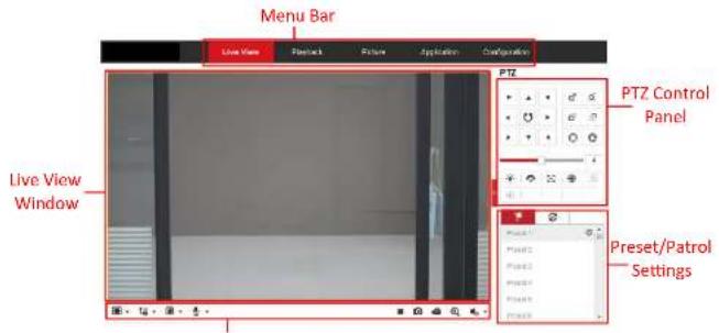
text_image
Menu Bar Live View Playset1 Picture Application Configuration PTZ Control Panel Live View Window Preset/Patchol SettingsFor IE (Internet Explorer) users, plug-ins as webcomponents and quick time are selectable. And for Non-IE users, webcomponents, quick time, VLC or MJPEG are selectable if they are supported by the web browser.
Note:
For camera that supports plug-in free live view, when Google Chrome 45 and its above version or Mozilla Firefox 52 and its above version are used, plug-in installation is not required. But Picture and Playback functions are hidden. To use mentioned function via web browser, change to their lower versions, or change to Internet Explorer 8.0 and its above version.
PTZ Control:
Perform panning, tilting and zooming actions of the camera. Control the light and the wiper (only available for cameras supporting PTZ function).
Preset/Patrol Settings:
Set/call/delete the presets or patrols for PTZ cameras.
5.2 Starting Live View
In the live view window as shown in Figure 4-2, click ▶ on the toolbar to start the live view of the camera
Network Camera User Manual
| Icon | Description |
| Manually capture the picture. | |
| Manually start/stop recording. | |
| Audio on and adjust volume /Mute. | |
| Turn on/off microphone. | |
| Start/stop digital zoom function. |
Note: The icons vary according to the different camera models.
5.3 Recording and Capturing Pictures Manually
In the live view interface, click on the toolbar to capture the live pictures or click
to record the live view. The saving paths of the captured pictures and clips can be set on the Configuration > Local page. To configure remote scheduled recording, please refer to Section 6.1.
Note: The captured image will be saved as JPEG file or BMP file in your computer.
5.4 Operating PTZ Control
Purpose:
In the live view interface, you can use the PTZ control buttons to realize
Network Camera User Manual

text_image
PTZ 4Figure 5-3 PTZ Control Panel
Click the zoom/focus/iris buttons to realize lens control.
Notes:
- There are eight direction arrows ( , , , , , , , ) in the control panel. Click the arrows to realize adjustment in the relative positions.
- For the cameras which support lens movements only, the direction buttons are invalid.
Table 5-2 Descriptions of PTZ Control Panel
| Icon | Description |
| Zoom in/out | |
| Focus near/far | |
| Iris +/- |
Network Camera User Manual
- In the PTZ control panel, select a preset number from the preset list.
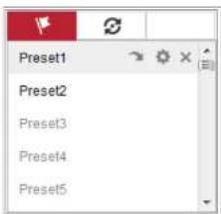
text_image
Preset1 Preset2 Preset3 Preset4 Preset5Figure 5-4 Setting a Preset
-
Use the PTZ control buttons to move the lens to the desired position.
-
Pan the camera to the right or left.
- Tilt the camera up or down.
- Zoom in or out.
-
Refocus the lens.
-
Click to finish the setting of the current preset.
-
You can click ✗ to delete the preset.
- Calling a Preset:
This feature enables the camera to point to a specified preset scene manually or when an event takes place.
Figure 5-5 Calling a Preset
5.4.3 Setting/Calling a Patrol
Note:
No less than 2 presets have to be configured before you set a patrol.
Steps:
- Click ⚙ to enter the patrol configuration interface.
- Select a path No., and click + to add the configured presets.
- Select the preset, and input the patrol duration and patrol speed.
- Click OK to save the first preset.
- Follow the steps above to add the other presets.

text_image
Patrol Path2 Preset Speed Time (s) 3 10 1 OK CancelFigure 5-6 Add Patrol Path
Chapter 6 Network Camera Configuration
6.1 Configure Local Parameters
Purpose:
The local configuration refers to the parameters of the live view, record files and captured pictures. The record files and captured pictures are the ones you record and capture using the web browser and thus the saving paths of them are on the PC running the browser.
Steps:
- Enter the Local Configuration interface: Configuration > Local.
- Configure the following settings:
● Live View Parameters: Set the protocol type and live view performance.
◆ Protocol Type: TCP, UDP, MULTICAST and HTTP are selectable.
TCP: Ensures complete delivery of streaming data and better video quality, yet the real-time transmission will be affected.
and the object detection is enabled as well, when a object is detected, it will be marked with a green rectangle on the live view.
◆ Display POS Information: Enable the function, feature information of the detected target is dynamically displayed near the target in the live image. The feature information of different functions are different. For example, ID and waiting time for Queue Management, height for People Counting, etc.
Note:
Display POS Information is only available for certain camera models.
◆ Image Format: Choose the image format for picture capture.

text_image
Live View Parameters Protocol ○ TCP ○ UDP ○ MULTICAST ○ HTTP Play Performance ○ Shortest Delay ○ Balanced ○ Fluent ● Custom 20 frame Rules ○ Enable ● Disable Display POS Information ○ Enable ● Disable Image Format ● JPEG ○ BMPFigure 6-1 Live View Parameters
- Record File Settings: Set the saving path of the recorded video files. Valid for the record files you recorded with the web browser.
Record File Size: Select the packed size of the manually recorded and downloaded video files to 256M, 512M or 1G. After the selection, the
Note: You can click Browse to change the directory for saving the clips and pictures, and click Open to open the set folder of clips and picture saving.
- Click Save to save the settings.
6.2 Configure System Settings
Purpose:
Follow the instructions below to configure the system settings, include System Settings, Maintenance, Security, and User Management, etc.
6.2.1 Configure Basic Information
Enter the Device Information interface: Configuration > System > System Settings > Basic Information.
In the Basic Information interface, you can edit the Device Name and Device No. Other information of the network camera, such as Model, Serial No., Firmware Version, Encoding Version, Number of Channels, Number of HDDs, Number of Alarm Input and Number of Alarm Output are displayed. The information cannot be changed in this menu. It is the reference for maintenance or modification in future.
Network Camera User Manual

text_image
Basic Information Time Settings RS232 RS485 DST Time Zone (GMT+08:00) Beijing, Urumqi, Singapore NTP ● NTP Server Address time.windows.com NTP Port 123 Interval 1440 min Test Manual Time Sync. ● Manual Time Sync. Device Time 2015-06-25T13:45:50 Set Time 2015-06-25T13:45:46 Sync. with computer timeFigure 6-2 Time Settings
- Select the Time Zone of your location from the drop-down menu.
- Configure the NTP settings.
(1) Click to enable the NTP function.
(2) Configure the following settings:
Server Address: IP address of NTP server.
NTP Port: Port of NTP server.
Note: If the camera is connected to a public network, you should use a NTP server that has a time synchronization function, such as the server at the National Time Center (IP Address: 210.72.145.44). If the camera is set in a customized network, NTP software can be used to establish a NTP server for time synchronization.
- Configure the manual time synchronization.
(1) Check the Manual Time Sync. item to enable the manual time synchronization function.
(2) Click the icon 📋 to select the date, time from the pop-up calendar.
(3) (Optional) You can check Sync. with computer time item to synchronize the time of the device with that of the local PC.

text_image
Sun Mon Tue Wed Thu Fri Sat 25 27 28 29 30 1 2 3 4 5 6 7 8 9 10 11 12 13 14 15 16 17 18 19 20 21 22 23 24 25 26 27 28 29 30 31 1 2 3 4 5 6 Time 18:57:36 OK 2015-05-18T18:57.36Figure 6-4 Time Sync Manually
Steps:
- Enter RS232 Port Setting interface: Configuration > System > System Settings > RS232.
- Configure the Baud Rate, Data Bit, Stop Bit, Parity, Flow Control, and Usage.

text_image
Basic Information Time Settings RS232 RS485 DST Baud Rate 115200 Data Bit 8 Stop Bit 1 Parity None Flow Ctrl None Usage Console SaveFigure 6-5 RS232 Settings
Note: If you want to connect the camera by the RS232 port, the parameters of the RS232 should be exactly the same with the parameters you configured here.
- Click Save to save the settings.
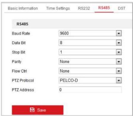
6.2.4 Configure RS485 Settings
Network Camera User Manual
text_image
Basic Information Time Settings RS232 RS485 DST RS485 Baud Rate 9600 Data Bit 8 Stop Bit 1 Parity None Flow Ctrl None PTZ Protocol PELCO-D PTZ Address 0 SaveFigure 6-6 RS-485 Settings
- Set the RS485 parameters and click Save to save the settings.
By default, the Baud Rate is set as 9600 bps, the Data Bit is 8, the stop bit is 1 and the Parity and Flow Control is None.
Note: The Baud Rate, PTZ Protocol and PTZ Address parameters should be exactly the same as the PTZ camera parameters.
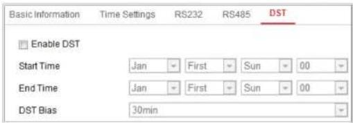
6.2.5 Configure DST Settings
Network Camera User Manual
text_image
Basic Information Time Settings RS232 RS485 DST Enable DST Start Time Jan First Sun 00 End Time Jan First Sun 00 DST Bias 30minFigure 6-7 DST Settings
- Select the start time and the end time.
- Select the DST Bias.
- Click Save to activate the settings.
6.2.6 Configure External Devices
Purpose:
For the device supported external devices, including the wiper on the housing or the LED light, you can control them via the Web browser. External devices vary according to the different camera models.
Steps:
- Enter the External Device configuration interface.
Configuration > System > System Settings > External Device
Network Camera User Manual
the Start Time and End Time.

text_image
LED Light On Timing Auto Start Time 18:00:00 End Time 06:00:00Figure 6-9 Set Schedule
● Auto: The LED will be turned on according to the environment illumination.
- Click Save to save the settings.
6.2.7 Configure VCA Resource
Purpose:
VCA resource offers you options to enable certain VCA functions according to actual need when several VCA functions are available. It helps allocate more resources to the desired functions.
Steps:
- Enter VCA Resource configuration interface:
Configuration > System > System Settings > VCA Resource - Select a desired VCA combination. Available VCA combination varies according to
6.3 Maintenance
6.3.1 Upgrade & Maintenance
Purpose:
The upgrade & maintenance interface allows you to process the operations, including reboot, partly restore, restore to default, export/import the configuration files, and upgrade the device.
Enter the Maintenance interface: Configuration > System > Maintenance > Upgrade
& Maintenance.
● Reboot: Restart the device.
- Restore: Reset all the parameters, except the IP parameters and user information, to the default settings.
● Default: Restore all the parameters to the factory default.
Notes:
-
After restoring the default settings, the IP address is also restored to the default IP address, please be careful for this action.
• For camera that supports Wi-Fi, wireless dial, or wlan function, Restore -
Click Import and input the encryption password that you set during exporting.
Note: You need to reboot the camera after importing configuration file.
- Upgrade: Upgrade the device to a certain version.
Steps:
- Select firmware or firmware directory to locate the upgrade file.
Firmware: Locate the exact path of the upgrade file.
Firmware Directory: Only the directory the upgrade file belongs to is required.
- Click Browse to select the local upgrade file and then click Upgrade to start remote upgrade.
Note: The upgrading process will take 1 to 10 minutes. Please don't disconnect power of the camera during the process, and the camera reboots automatically after upgrade.
6.3.2 Log
Purpose:
The operation, alarm, exception and information of the camera can be stored in log
Figure 6-10 Log Searching Interface
- Set the log search conditions to specify the search, including the Major Type, Minor Type, Start Time and End Time.
- Click Search to search log files. The matched log files will be displayed on the log list interface.

text_image
Start Time 2015-05-25 00:00:00 End Time 2015-05-25 23:59:59 Search Log List Export No. Time Major Type Minor Type Channel No. Local/Remote User Remote Host IP 1 2015-05-25 19:12:34 Operation Remote: Get Working Sta... admin 10.16.1.107 2 2015-05-25 19:12:12 Operation Remote: Get Working Sta... admin 10.16.1.107 3 2015-05-25 19:12:12 Operation Remote: Get Working Sta... admin 10.16.1.107 4 2015-05-25 19:12:12 Operation Remote: Get Working Sta... admin 10.16.1.107 5 2015-05-25 19:12:11 Operation Remote: Get Working Sta... admin 10.16.1.107 6 2015-05-25 19:12:11 Operation Remote: Get Working Sta... admin 10.16.1.107 7 2015-05-25 19:12:11 Operation Remote: Get Working Sta... admin 10.16.1.107 8 2015-05-25 19:12:10 Operation Remote: Get Working Sta... admin 10.16.1.107 9 2015-05-25 19:09:28 Operation Remote: Get Parameters admin 10.16.1.107 10 2015-05-25 19:09:25 Operation Remote: Get Parameters admin 10.16.1.107 11 2015-05-25 19:09:25 Operation Remote: Get Parameters admin 10.16.1.107 12 2015-05-25 19:09:24 Operation Remote: Get Parameters admin 10.16.1.107 Total 614 Items 1/7 >>Figure 6-11 Log Searching
4 To export the log files, click Export to save the log files
Third Stream to enable the function.
6.4 Security Settings
Configure the parameters, including Authentication, IP Address Filter, and Security Service from security interface.
6.4.1 Authentication
Purpose:
You can specifically secure the stream data of live view.
Steps:
- Enter the Authentication interface: Configuration > System > Security >
Authentication.

text_image
Authentication IP Address Filter Security Service RTSP Authentication digest WEB Authentication digestFigure 6-12 Authentication
Network Camera User Manual
Address Filter
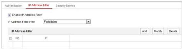
text_image
Authentication IP Address Filter Security Service Enable IP Address Filter IP Address Filter Type Forbidden IP Address Filter Add Modify Delete No. IPFigure 6-13 IP Address Filter Interface
- Check the checkbox of Enable IP Address Filter.
- Select the type of IP Address Filter in the drop-down list, Forbidden and Allowed are selectable.
- Set the IP Address Filter list.
- Add an IP Address
Steps:
(1) Click the Add to add an IP.
(2) Input the IP Adrees.
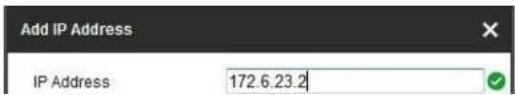
text_image
Add IP Address IP Address 172.6.23.2Network Camera User Manual
text_image
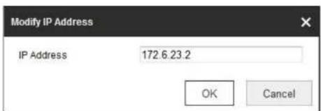
Modify IP Address IP Address 172.6.23.2 OK CancelFigure 6-15 Modify an IP
(3) Click the OK to finish modifying.
- Delete an IP Address or IP Addresses.
Select the IP address(es) and click Delete.
- Click Save to save the settings.
6.4.3 Security Service
To enable the remote login, and improve the data communication security, the camera provides the security service for better user experience.
Steps:
- Enter the security service configuration interface: Configuration > System >
Security > Security Service.
Authentication
IP Address Filter
Security Service
6.5 User Management
6.5.1 User Management
- As Administrator
The admin user can add, delete or modify user accounts, and grant them different permissions. We highly recommend you manage the user accounts and permissions properly.
Enter the User Management interface: Configuration > System > User Management
Note:
Admin password if required for adding and modifying a user account.

text_image
User Management Online Users User List Security Question Add Mostly Close No User Name Level 1 admin Administrator 2 test 01 OperatorFigure 6-17 User Management Interface

STRONG PASSWORD RECOMMENDED—We highly recommend you create a strong password of your own choosing (using a minimum of 8 characters, including at least three of the following categories: upper case letters, lower case letters, numbers, and special characters) in order to increase the security of your product. And we recommend you reset your password regularly, especially in the high security system, resetting the password monthly or weekly can better protect your product.
- You can check or uncheck the permissions for the new user.
- Click OK to finish the user addition.
- Modifying a User
Steps:
- Left-click to select the user from the list and click Modify.
- Modify the User Name, Level and Password.

STRONG PASSWORD RECOMMENDED-We highly recommend you create a strong password of your own choosing (using a minimum of 8 characters, including at least three of the following categories: upper case letters, lower case letters, numbers, and special characters) in order to increase the security of your product. And we recommend you reset your password
6.5.2 Security Question
Purpose:
Security question is used to reset the admin password when admin user forgets the password.
Set Security Question:
You can set the security questions during camera activation. Or you can set the function at user management interface.
Security question setting is not cleared when you restore the camera (not to default).
Steps:
- Enter setting interface:
Configuration > System > User Management > User Management
- Click Security Question.
- Input correct admin password.
- Select questions and input answers.
- Click OK to save the settings.
Reset Admin Password:
Before you start:
6.5.3 Online Users
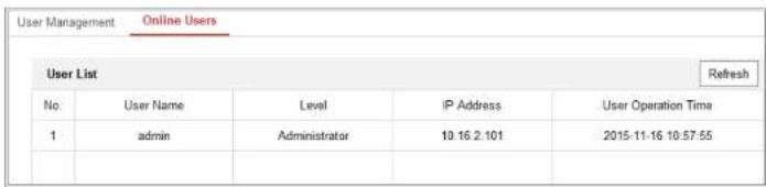
Purpose:
You can see the current users who are visiting the device through this interface. User information, such as user name, level, IP address, and operation time, is displayed in the User List.
Click Refresh to refresh the list.
text_image
User Management Online Users User List Refresh No. User Name Level IP Address User Operation Time 1 admin Administrator 10.16.2.101 2015-11-16 10:57:55Figure 6-18 View the Online Users
Chapter 7 Network Settings
Purpose:
Follow the instructions in this chapter to configure the basic settings and advanced settings.
7.1 Configure Basic Settings
Purpose:
You can configure the parameters, including TCP/IP, DDNS, PPPoE, Port, and NAT, etc., by following the instructions in this section.
7.1.1 Configure TCP/IP Settings
Purpose:
TCP/IP settings must be properly configured before you operate the camera over network. The camera supports both the IPv4 and IPv6. Both versions can be configured simultaneously without conflicting to each other, and at least one IP version should be configured.
Network Camera User Manual

text_image
TCP/IP DDNS PPPoE Port NAT NIC Type Auto DHCP IPv4 Address 10.11.37.120 Test IPv4 Subnet Mask 255.255.255.0 IPv4 Default Gateway 10.11.37.254 IPv6 Mode Route Advertisement View Route Advertisement IPv6 Address IPv6 Subnet Mask 0 IPv6 Default Gateway Mac Address 60.56.e3 60.27.5d MTU 1500 Multicast Address Enable Multicast Discovery DNS Server Preferred DNS Server 8.8.8.8 Alternate DNS Server SaveFigure 7-1 TCP/IP Settings
- Configure the basic network settings, including the NIC Type, IPv4 or IPv6 Address, IPv4 or IPv6 Subnet Mask, IPv4 or IPv6 Default Gateway, MTU settings and
multicast group address. Before utilizing this function, you have to enable the Multicast function of your router.
● A reboot is required for the settings to take effect.
7.1.2 Configure DDNS Settings
Purpose:
If your camera is set to use PPPoE as its default network connection, you can use the Dynamic DNS (DDNS) for network access.
Before you start:
Registration on the DDNS server is required before configuring the DDNS settings of the camera.
Steps:
- Enter the DDNS Settings interface: Configuration > Network > Basic Settings > DDNS.
- Check the Enable DDNS checkbox to enable this feature.
- Select DDNS Type. Two DDNS types are selectable: DynDNS and NO-IP.
• DynDNS:
Steps:
Network Camera User Manual

text_image
TCP/IP DDNS PPPoE Port NAT Enable DDNS DDNS Type DynDNS Server Address members dyndns.org Domain 123.dyndns.com User Name test Port 0 Password •••••••• Confirm ••••••••• SaveFigure 7-2 DynDNS Settings
NO-IP:
Steps:
(1) Choose the DDNS Type as NO-IP.
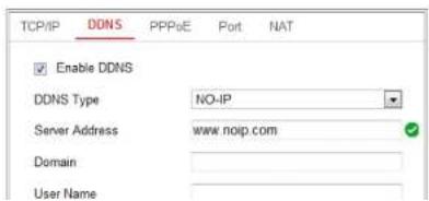
text_image
TCP/IP DONS PPPoE Port NAT Enable DDNS DDNS Type NO-IP Server Address www.noip.com Domain User Name7.1.3 Configure PPPoE Settings
Steps:
- Enter the PPPoE Settings interface: Configuration > Network > Basic Settings >
PPPoE
text_image
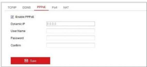
TCP/IP DDNS PPPoE Port NAT Enable PPPoE Dynamic IP 0.0.0 UserName Password Confirm SaveFigure 7-4 PPPoE Settings
- Check the Enable PPPoE checkbox to enable this feature.
- Enter User Name, Password, and Confirm password for PPPoE access.
Note: The User Name and Password should be assigned by your ISP.

- For your privacy and to better protect your system against security risks, we strongly recommend the use of strong passwords for all functions and network
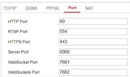
You can set the port No. of the camera, e.g., HTTP port, RTSP port and HTTPS port.
Steps:
- Enter the Port Settings interface, Configuration > Network > Basic Settings > Port
text_image
TCP/IP DDNS PPPoE Port NAT HTTP Port 80 RTSP Port 554 HTTPS Port 443 Server Port 8000 WebSocket Port 7681 WebSockets Port 7682Figure 7-5 Port Settings
- Set the ports of the camera.
HTTP Port: The default port number is 80, and it can be changed to any port No. which is not occupied.
RTSP Port: The default port number is 554 and it can be changed to any port No. ranges from 1 to 65535.
HTTPS Port: The default port number is 443, and it can be changed to any port
Note:
WebSocket and WebSockets protocol are used for plug-in free live view. For detailed information, see 7.2.11.
3. Click Save to save the settings.
Note: A reboot is required for the settings to take effect.
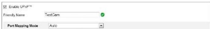
7.1.5 Configure NAT (Network Address Translation) Settings
Purpose:
NAT interface allows you to configure the UPnP™ parameters.
Universal Plug and Play (UPnP™) is a networking architecture that provides compatibility among networking equipment, software and other hardware devices.
The UPnP protocol allows devices to connect seamlessly and to simplify the implementation of networks in the home and corporate environments.
With the function enabled, you don't need to configure the port mapping for each port, and the camera is connected to the Wide Area Network via the router.
text_image
Enable UPnP™ Friendly Name TestCam Port Mapping Mode Auto- Choose a friendly name for the camera, or you can use the default name.
- Select the port mapping mode. Manual and Auto are selectable.
Note:
If you select Auto, you should enable UPnP™ function on the router.
If you select Manual, you can customize the value of the external port and complete port mapping settings on router manually.
- Click Save to save the settings.
7.2 Configure Advanced Settings
Purpose:
You can configure the parameters, including SNMP, FTP, Email, HTTPS, QoS, 802.1x, etc., by following the instructions in this section.
7.2.1 Configure SNMP Settings
Purpose:
You can set the SNMP function to get camera status, parameters and alarm related information, and manage the camera remotely when it is connected to the network.
strongly recommend the use of strong passwords for all functions and network devices. The password should be something of your own choosing (using a minimum of 8 characters, including at least three of the following categories: upper case letters, lower case letters, numbers and special characters) in order to increase the security of your product.
- Proper configuration of all passwords and other security settings is the responsibility of the installer and/or end-user.
Steps:
- Enter the SNMP Settings interface: Configuration > Network > Advanced Settings > SNMP.
Network Camera User Manual

text_image
SNMP v1/v2 Enable SNMPv1 Enable SNMP v2c Read SNMP Community public Write SNMP Community private Trap Address Trap Port 162 Trap Community public SNMP v3 Enable SNMPv3 Read UserName Security Level=no auth, no priv Authentication Algorithm MDS SHA Authentication Password**** Private-key Algorithm DES AES Private-key password**** Write UserName Security Level=no auth, no priv Authentication Algorithm MDS SHA Authentication Password**** SNMP v1/v2 SNMP v3configure here.
- Click Save to save and finish the settings.
Notes:
• A reboot is required for the settings to take effect.
- To lower the risk of information leakage, you are suggested to enable SNMP v3 instead of SNMP v1 or v2.
7.2.2 Configure FTP Settings
Purpose:
You can configure the FTP server related information to enable the uploading of the captured pictures to the FTP server. The captured pictures can be triggered by events or a timing snapshot task.
Steps:
- Enter the FTP Settings interface: Configuration > Network > Advanced Settings > FTP.
| SNMP | FTP | HTTPS | QoS | 802.1x | |
| Server Address | 0.0.0.0 | ||||
| Port | 21 | ||||
FTP server login.

- For your privacy and to better protect your system against security risks, we strongly recommend the use of strong passwords for all functions and network devices. The password should be something of your own choosing (using a minimum of 8 characters, including at least three of the following categories: upper case letters, lower case letters, numbers and special characters) in order to increase the security of your product.
-
Proper configuration of all passwords and other security settings is the responsibility of the installer and/or end-user.
-
Set the directory structure and picture filing interval.
Directory: In the Directory Structure field, you can select the root directory, parent directory and child directory. When the parent directory is selected, you have the option to use the Device Name, Device Number or Device IP for the name of the directory; and when the Child Directory is selected, you can use the Camera Name or Camera No. as the name of the directory.
Picture Filing Interval: For better picture management, you can set the picture filing interval from 1 day to 30 days. Pictures captured in the same time interval
anonymous access to the FTP server.
Note: The anonymous access function must be supported by the FTP server.
- Click Save to save the settings.
7.2.3 Configure Email Settings
Purpose:
The system can be configured to send an Email notification to all designated receivers if an alarm event is detected, e.g., motion detection event, video loss, video tampering, etc.
Before you start:
Please configure the DNS Server settings under Configuration > Network > Basic
Settings > TCP/IP before using the Email function.
Steps:
- Enter the TCP/IP Settings (Configuration > Network > Basic Settings > TCP/IP) to set the IPv4 Address, IPv4 Subnet Mask, IPv4 Default Gateway and the Preferred DNS Server.
Note: Please refer to Section 7.1.1 Configure TCP/IP Settings for detailed information.
SMTP port should be set as 465 for this encryption method. When you select SSL or TLS and enable STARTTLS, emails will be sent after encrypted by STARTTLS, and the SMTP port should be set as 25.
Note: If you want to use STARTTLS, make sure that the protocol is supported by your e-mail server. If you check the Enable STARTTLS checkbox when the protocol is not supported by your e-mail server, your e-mail will not be encrypted.
Attached Image: Check the checkbox of Attached Image if you want to send emails with attached alarm images.
Interval: The interval refers to the time between two actions of sending attached pictures.
Authentication (optional): If your email server requires authentication, check this checkbox to use authentication to log in to this server and input the login user name and password.

- For your privacy and to better protect your system against security risks, we strongly recommend the use of strong passwords for all functions and network devices. The password should be something of your own choosing (using a minimum of 8 characters, including at least three of the following
Network Camera User Manual

text_image
SNMP FTP Email HTTPS QoS 802.1x Sender test Senders Address test@gmail.com SMTP Server SMTP Port 25 E-mail Encryption None Attached Image Interval 2 Authentication User Name Password Confirm Receiver No. Receiver Receiver's Address Test 1 2 3 SaveFigure 7-9 Email Settings
- Click Save to save the settings.
7.2.4 Platform Access
If you select Platform Access Mode as Hik-Connect,
1) Click and read "Terms of Service" and "Privacy Policy" in pop-up window.
2) Create a verification code or change the verification code for the camera.
Note:
- The verification code is required when you add the camera to Hik-Connect app.
-
For more information about the Hik-Connect app, refer to Hik-Connect Mobile Client User Manual.
-
You can use the default server address. Or you can check the Custom checkbox on the right and input a desired server address.
- Click Save to save the settings.
7.2.5 Wireless Dial
Purpose:
Data stream of audio, video and image can be transferred via 3G/4G wireless network.
Notes:
• The wireless dial function may not be supported by some camera models.
protocol. You can also leave these parameters blank, and the device will adopt the default settings for dialing after other parameters are configured.
3) Select the network mode from the drop-down list. Auto, 3G and 4G are selectable. If Auto is selected, the network selection priority comes as: 4G > 3G > Wired Network.
4) Input the offline time if Manual is selected as the dial mode.
5) Input the UIM Number (Mobile Phone Number).
6) Click the Edit button to set the arming schedule if Auto is selected as the dial mode.
7) Click Save to save the settings.
4. View the dial status.
1) Click the Refresh button to view the dial status including real-time mode, UIM status, signal strength, etc.
2) If Manual is selected as the dial mode, you can also manually connect / disconnect the wireless network.
5. Set the authorized list. The mobile phone number on the authorized list can receive the alarm message from the device and reboot the device via SMS.
1) Check the checkbox of Enable SMS Alarm.
7.2.6 HTTPS Settings
Purpose:
HTTPS provides authentication of the web site and its associated web server, which protects against Man-in-the-middle attacks.
Note:
- For the camera that supports plug-in free live view, when you use HTTPS to visit the camera, you should enable Websockets for live view. Go to Configuration > Network > Advanced Settings > Network Service.
- If HTTPS is enabled by default, the camera creates an unsigned certificate automatically. When you visit the camera via HTTPS, the web browser will send a notification about the certificate issue. Install a signed-certificate to the camera to cancel the notification.
Steps:
- Enter the HTTPS settings interface. Configuration > Network > Advanced Settings > HTTPS.
- Check Enable to access the camera via HTTP or HTTPS protocol.
- Check Enable HTTPS Browsing to access the camera only via HTTPS protocol.
Figure 7-11 Create Self-signed Certificate
• Create the self-signed certificate
(1) Select Create Self-signed Certificate as the Installation Method.
(2) Click Create button to enter the creation interface.
(3) Enter the country, host name/IP, validity and other information.
(4) Click OK to save the settings.
Note: If you already had a certificate installed, the Create Self-signed Certificate is grayed out.
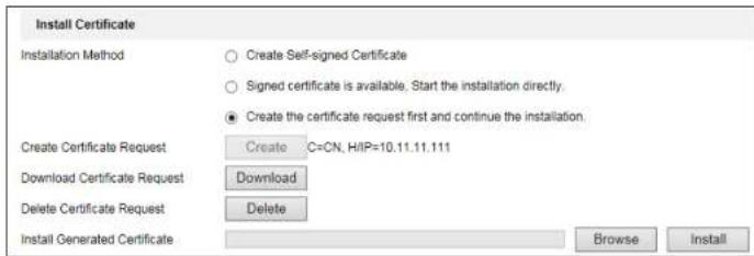
- Create the request and import the authorized certificate
(1) Select Create the certificate request first and continue the installation as the Installation Method.
(2) Click Create button to create the certificate request. Fill in the required information in the popup window.
(3) Click Download to download the certificate request and submit it to the trusted certificate authority for signature.
(4) After receiving the signed valid certificate, you can import the certificate in two ways:
a) Select Signed certificate is available, Start the installation directly. Click
Network Camera User Manual
text_image
Install Certificate Installation Method Create Self-signed Certificate Signed certificate is available, Start the installation directly. ● Create the certificate request first and continue the installation. Create Certificate Request Create C=CN, HIP=10.11.11.111 Download Certificate Request Download Delete Certificate Request Delete Install Generated Certificate Browse InstallFigure 7-13 Import the Certificate (2)
- There will be the certificate information after your successfully creating and installing the certificate.
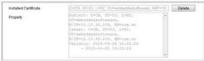
text_image
Installed Certificate C=CN, ST=ZJ, L=HZ, OU=embeddedsoftware, H/IP=10 Property Subject: C=CN, ST=ZJ, L=HZ, OU=embeddedsoftware, H/IP=19.13.33.209, EN=com.cn Issuer: C=CN, ST=ZJ, L=HZ, OU=embeddedsoftware, H/IP=19.13.33.209, EN=com.cn Validity: 2015-04-28 14:28:24 - 2015-04-28 14:25:24Figure 7-14 Installed Certificate
- Export and save the certificate for verification when adding the device to client software.
QoS

text_image
SNMP FTP Email HTTPS QoS 802.1x Video/Audio DSCP 0 Event/Alarm DSCP 0 Management DSCP 0 SaveFigure 7-15 QoS Settings
- Configure the QoS settings, including Video/Audio DSCP, Event/Alarm DSCP and Management DSCP.
The valid value range of the DSCP is 0 to 63. The bigger the DSCP value is, the higher the priority is.
Note: DSCP refers to the Differentiated Service Code Point; and the DSCP value is used in the IP header to indicate the priority of the data.
- Click Save to save the settings.
Note: A reboot is required for the settings to take effect.
7.2.8 Configure 802.1X Settings
Network Camera User Manual
minimum of 8 characters, including at least three of the following categories: upper case letters, lower case letters, numbers and special characters) in order to increase the security of your product.
- Proper configuration of all passwords and other security settings is the responsibility of the installer and/or end-user.
Steps:
- Enter the 802.1X Settings interface, Configuration > Network > Advanced Settings > 802.1X
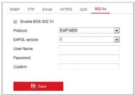
text_image
SNMP FTP Email HTTPS QoS 802.1x Enable IEEE 802.1X Protocol EAP-MD5 EAPOL version 1 User Name Password Confirm SaveFigure 7-16 802.1X Settings
- Check the Enable IEEE 802.1X checkbox to enable the feature.
can configure ONVIF user in this interface. Refer to ONVIF standard for detailed configuration rules.
CGI
Check the Enable Hikvision_CGI checkbox and then select the authentication from the drop-down list.
Note: Digest is the recommended authentication method.
ONVIF
Steps:
- Check the Enable ONVIF checkbox to enable the function.
- Add ONVIF users. Up to 32 users are allowed.
Set the user name and password, and confirm the password. You can set the user as media user, operator, and administrator.
Note: ONVIF user account is different from the camera user account. You have set ONVIF user account independently.
- Save the settings.
Note: User settings of ONVIF are cleared when you restore the camera.
7.2.10 Bandwidth Adaptation
WebSocket and WebSockets
WebSocket or WebSockets protocol should be enabled if you use Google Chrome 45 and its above version or Mozilla Firefox 52 and its above version to visit your camera. Otherwise, live view, image capture, and digital zoom function can not be used.
If the camera uses HTTP, enable WebSocket.
If the camera uses HTTPS, enable WebSockets.
SDK Service and Enhanced SDK Service
If you want to add the device to the client software, you should enable SDK Service or Enhanced SDK Service.
SDK Service: SDK protocol is used.
Enhanced SDK Service: SDK over TLS protocol is used. Communication between the device and the client software is secured by using TLS (Transport Layer Security) protocol.
TLS (Transport Layer Security)
The device offers TLS 1.1 and TLS 1.2. Enable one or more protocol versions according to your need.
7 2 12 Smooth Streaming
Network Camera User Manual

text_image
SNMP FTP Email Platform Access HTTPS QoS 802.1x Integration Protocol Network Services Smooth Streaming Stream Type Third Stream Enable Smooth Streaming Mode Auto SaveFigure 7-17 Smooth Streaming Settings
- Select the Stream Type.
- Check Enable Smooth Streaming.
Note: Be sure the Bitrate Type is selected as Constant and the SVC is selected as OFF before enable this function. Go to Configuration > Video/Audio > Video page to set the parameters.
- Select the mode of smooth streaming. There are three modes selectable: Auto, Resolution Priority, and Error Correction.
Auto: The resolution and bitrate will be adjusted automatically and resolution will take the priority. The upper limits of these two parameters will not exceed the values you set on Video page. Go to Configuration > Video/Audio > Video page, set the Resolution and Max. Bitrate before you enable smooth streaming function. And in this mode the framerate will be adjusted to Max. value automatically.
retransmission. When the proportion is higher than 0, the error data will be corrected via redundant data that is added to the stream and data retransmission. The higher the value is, the more redundant date will be generated, the more data error will be corrected, and the larger bandwidth is required. When the proportion is 100, the redundant data will be as large as the original data, and the bandwidth is twice required.
Note: Be sure the bandwidth is sufficient in Error Correction mode.
- Click Save to save the settings.
Chapter 8 Video/Audio Settings
Purpose:
Follow the instructions below to configure the video setting, audio settings, ROI,
Display info. on Stream, etc.
8.1 Configure Video Settings
For certain camera models, you can configure parameters for available video streams, for example, the main stream, the sub-stream, etc. And you can also customize additional video streams for further needs.
• On Video page, set-up available video streams.
• On Custom Video page, add extra video streams
8.1.1 Video Settings
Steps:
- Enter the Video Settings interface, Configuration > Video/Audio > Video
| Video | Custom Video | Audio | ROI | Display Info. on Stream | Target Cro |
Figure 8-1 Video Settings
- Select the Stream Type.
Supported stream types are listed in the drop-down list.
Notes:
- For some models, the Third Stream is not enabled by default. Go to System > Maintenance > System Service> Software to enable the function is required.
-
The main stream is usually for recording and live view with good bandwidth, and the sub-stream can be used for live view when the bandwidth is limited.
-
You can customize the following parameters for the selected stream type.
Video Type:
Select the stream type to video stream, or video & audio composite stream. The audio signal will be recorded only when the Video Type is Video & Audio.
Resolution:
Select the resolution of the video output.
Bitrate Type:
Select the bitrate type to constant or variable.
Video Quality:
When bitrate type is selected as Variable, 6 levels of video quality are selectable.
The camera supports multiple video encodings types, such as H.264, H.265, MJPEG, and MPEG4. Supported encoding type for different stream types may differ. H.265 is a new encoding technology. Compared with H.264, it reduces the transmission bitrate under the same resolution, frame rate and image quality.
Note: Selectable video encoding types may vary according to different camera modes.
H.264+ and H.265+:
- H.264+: If you set the main stream as the stream type, and H.264 as the video encoding, you can see H.264+ available. H.264+ is an improved compression coding technology based on H.264. By enabling H.264+, users can estimate the HDD consumption by its maximum average bitrate. Compared to H.264, H.264+ reduces storage by up to 50% with the same maximum bitrate in most scenes.
- H.265+: If you set the main stream as the stream type, and H.265 as the video encoding, you can see H.265+ available. H.265+ is an improved compression coding technology based on H.265. By enabling H.265+, users can estimate the HDD consumption by its maximum average bitrate. Compared to H.265, H.265+ reduces storage by up to 50% with the same maximum bitrate in
the requirements of the actual scene in order to realize the set maximum average bitrate in the long term. The camera needs at least 24 hours to adapt to a fixed monitoring scene.
Max. Average Bitrate:
When you set a maximum bitrate, its corresponding recommended maximum average bitrate will be shown in the Max. Average Bitrate box. You can also set the maximum average bitrate manually from 32 Kbps to the value of the set maximum bitrate.
Profile:
When you select H.264 or H.265 as video encoding, you can set the profile. Selectable profiles vary according to camera models.
I Frame Interval:
Set I Frame Interval from 1 to 400.
SVC:
Scalable Video Coding is an extension of the H.264/AVC and H.265 standard. Select OFF/ON to disable/enable the SVC function. Select Auto and the device will automatically extract frames from the original video when the network bandwidth is insufficient.
8.1.2 Custom Video
You can set up additional video streams if required. For custom video streams, you can live view them, but cannot record or playback them.
Notes:
- Custom video function requires the support of the camera.
- After a camera restore action (not restore to default setting), quantity of custom video streams and their names are kept, but the related parameters are restored.
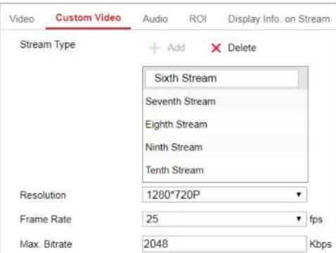
text_image
Video Custom Video Audio ROI Display Info. on Stream Stream Type + Add × Delete Sixth Stream Seventh Stream Eighth Stream Ninth Stream Tenth Stream Resolution 1280*720P Frame Rate 25 fps Max. Bitrate 2048 KbpsNetwork Camera User Manual
encoding). For parameter introduction, see Section 8.1.1.
- (Optional) Add stream description is needed.
- (Optional) If a custom stream is not needed, click ✗ to delete it.
- Save the settings.
8.2 Configure Audio Settings
Steps:
- Enter the Audio Settings interface: Configuration > Video/Audio > Audio.
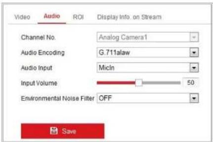
text_image
Video Audio ROI Display Info. on Stream Channel No. Analog Camera1 Audio Encoding G.711alaw Audio Input Micin Input Volume 50 Environmental Noise Filter OFF SaveFigure 8-3 Audio Settings
- Configure the following settings.
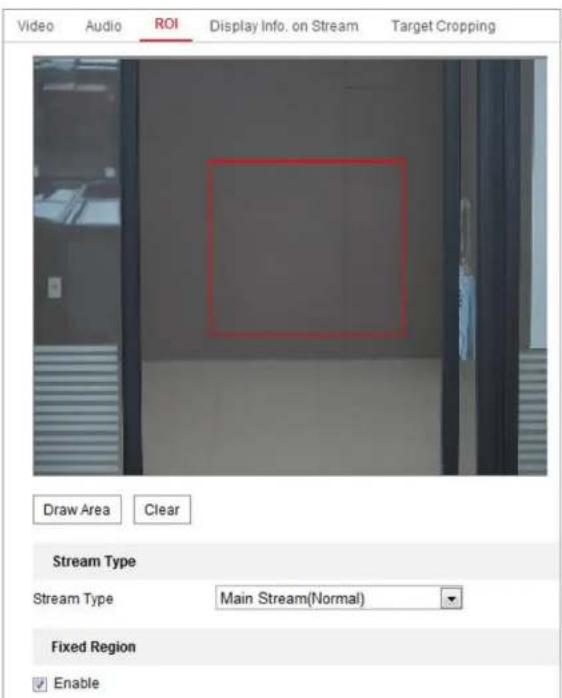
8.3 Configure ROI Encoding
Purpose:
ROI (Region of Interest) encoding helps to discriminate the ROI and background information in video compression, which means, the technology assigns more encoding resource to the region of interest, thus to increase the quality of the ROI whereas the background information is less focused.
Note: ROI function varies according to different camera models.
Network Camera User Manual
text_image
Video Audio ROI Display Info. on Stream Target Cropping Draw Area Clear Stream Type Stream Type Main Stream(Normal) Fixed Region Enable4. Set Fixed Region for ROI.
(1) Select the Region No. from the drop-down list.
(2) Check the Enable checkbox to enable ROI function for the chosen region.
(3) Click Drawing. Click and drag the mouse on the view screen to draw a red rectangle as the ROI region. You can click Clear to cancel former drawing. Click Stop Drawing when you finish.
(4) Select the ROI level.
(5) Enter a region name for the chosen region.
(6) Click Save the save the settings of ROI settings for chosen fixed region.
(7) Repeat steps (1) to (6) to setup other fixed regions.
5. Set Dynamic Region for ROI.
(1) Check the checkbox to enable Object tracking.
Note: To enable object tracking function, the object detection function should be supported and enabled.
(2) Select the ROI level.
6. Click Save to save the settings.
Note: ROI level means the image quality enhancing level. The larger the value is, the better the image quality would be.
8.5 Configure Target Cropping
Purpose:
You can specify a target area on the live video, and then the specified video area can be displayed via the third stream in certain resolution, providing more details of the target area if needed.
Note: Target cropping function varies according to different camera models.
Steps:
- Enter the Target Cropping settings interface.
- Check Enable Target Cropping checkbox to enable the function.
- Set Third Stream as the stream type.
- Select the cropping resolution for the video display of target area. A red rectangle is displayed on the live video to mark the target area, and you can click-and-drag the rectangle to locate the target area as desired.
- Click Save to save the settings.
Chapter 9 Image Settings
Purpose:
Follow the instructions in this chapter to configure the image parameters, including display settings, OSD settings, privacy mask, and picture overlay.
9.1 Configure Display Settings
Purpose:
Configure the image adjustment, exposure settings, day/night switch, backlight settings, white balance, image enhancement, video adjustment, and other parameters in display settings.
Note: The display parameters vary according to the different camera models. Please refer to the actual interface for details.
9.1.1 Day/Night Auto-Switch
Steps:
-
Enter the Display Settings interface, Configuration > Image > Display Settings.
-
Set the image parameters of the camera.
Note: In order to guarantee the image quality in different illumination, it provides two sets of parameters for users to configure.
- Image Adjustment
Brightness describes bright of the image, which ranges from 1 to 100.
Contrast describes the contrast of the image, which ranges from 1 to 100.
Saturation describes the colorfulness of the image color, which ranges from 1 to 100.
Sharpness describes the edge contrast of the image, which ranges from 1 to 100.
- Exposure Settings
If the camera is equipped with the fixed lens, only Manual is selectable, and the iris mode is not configurable.
If Auto is selected, you can set the auto iris level from 0 to 100.
The Exposure Time refers to the electronic shutter time, which ranges from 1 to 1/100,000s. Adjust it according to the actual luminance condition.
Gain of image can also be manually configured from 0 to 100. The bigger the value is, the brighter would the image be, and the noise would also be amplified
Manual: You can control the lens by adjusting the zoom, focus, lens initialization, and auxiliary focus manually.
Semi-Auto: Camera will focus automatically when you adjust the zoom parameters.
Day/Night Switch
Select the Day/Night Switch mode according to different monitoring demand. Day, Night, Auto, Scheduled-Switch, and Triggered by alarm input are selectable for day/night switch.
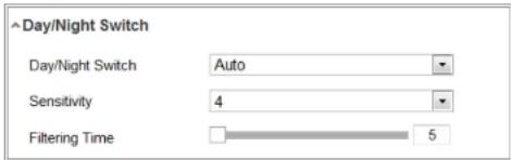
text_image
Day/Night Switch Day/Night Switch Auto Sensitivity 4 Filtering Time 5Figure 9-3 Day/Night Switch
Day: the camera stays at day mode.
Night: the camera stays at night mode.
Auto: the camera switches between the day mode and the night mode according to the illumination automatically. The sensitivity ranges from 0 to 7, the higher the value is. the easier the mode switches. The Filtering Time refers to the
Select Manual, and you can adjust the supplement by adjusting the distance. E.g., if the object is near the camera, the device adjusts the supplement light to lower power, and the light is in higher power if the object is far away.
- Backlight Settings
BLC Area: If you focus on an object against strong backlight, the object will be too dark to be seen clearly. BLC compensates light to the object in the front to make it clear. OFF, Up, Down, Left, Right, Center, Auto, and Custom are selectable.
Note: If BLC mode is set as Custom, you can draw a red rectangle on the live view image as the BLC area.
WDR: Wide Dynamic Range can be used when there is a high contrast of the bright area and the dark area of the scene.
HLC: High Light Compression function can be used when there are strong lights in the scene affecting the image quality.
- White Balance
White balance is the white rendition function of the camera used to adjust the color temperature according to the environment.
Defog Mode: You can enable the defog function when the environment is foggy and the image is misty. It enhances the subtle details so that the image appears clearer.
EIS (Electrical Image Stabilizer): EIS reduces the effects of vibration in a video.
Grey Scale: You can choose the range of the grey scale as [0-255] or [16-235].
- Video Adjustment
Mirror: It mirrors the image so you can see it inversed. Left/Right, Up/Down, Center, and OFF are selectable.
Rotate: To make a complete use of the 16:9 aspect ratio, you can enable the rotate function when you use the camera in a narrow view scene.
When installing, turn the camera to the 90 degrees or rotate the 3-axis lens to 90 degrees, and set the rotate mode as on, you will get a normal view of the scene with 9:16 aspect ratio to ignore the needless information such as the wall, and get more meaningful information of the scene.
Scene Mode: Choose the scene as indoor or outdoor according to the real environment.
Video Standard: 50 Hz and 60 Hz are selectable. Choose according to the different video standards; normally 50 Hz for PAL standard and 60 Hz for NTSC
Network Camera User Manual
illumination.
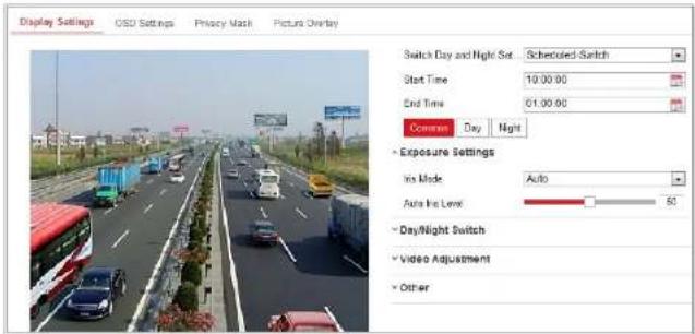
text_image
Display Settings OSD Settings Privacy Mask Picture Overlay Switch Day and Night Set Scheduled Switch Start Time 10:00:00 End Time 01:00:00 Commute Day Night Exposure Settings Air Mode Auto Auto Line Low: 60 Day/Night Switch Video Adjustment OtherFigure 9-5 Day/Night Scheduled-Switch Configuration Interface
Steps:
- Click the calendar icon to select the start time and the end time of the switch.
Notes:
• The start time and end time refer to the valid time for day mode.
- The time period can start and end on two days in a row. For example, if you set start time as 10:00 and end time as 1:00, the day mode will be activated at 10 o'clock in the morning and stopped at 1 o'clock early in the next morning.
Network Camera User Manual
displayed on the live view.

text_image
11- 16 2015 Mon'03:01 Display Settings OSD Settings Privacy Mask Picture Overlay Display Name Display Date Display Week Camera Frame Camera 01 Time Format 24-hour Date Format MM-DD-YYYY Text Over-Lay 1 item1 2 item2 3 item3 4 5 6 7 8 Display Mode Not transparent & Not flashing OSD Size Auto Font Color Black&White Self-adaptive Alignment Align Left ScanFigure 9-6 OSD Settings
Steps:
- Enter the OSD Settings interface: Configuration > Image > OSD Settings.
- Check the corresponding checkbox to select the display of camera name, date or week if required.
2 Edit the camera name in the text field of Camera Name
Note: The alignment adjustment is only applicable to Text Overlay items.
- Click Save to save the settings.
9.3 Configure Privacy Mask
Purpose:
Privacy mask enables you to cover certain areas on the live video to prevent certain spots in the monitoring area from being live viewed and recorded.
Steps:
- Enter the Privacy Mask Settings interface: Configuration > Image > Privacy Mask.
- Check the checkbox of Enable Privacy Mask to enable this function.
- Click Draw Area.
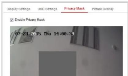
text_image
Display Settings OSD Settings Privacy Mask Picture Overlay Enable Privacy Mask 07-23-2015 Thu 14:00:39Network Camera User Manual
set without saving them.
- Click Save to save the settings.
9.4 Configure Picture Overlay
Purpose:
Picture overlay enables you to overlay a picture on the image. This function enables a certain enterprise or users to overlay their logo on the image.
Steps:
- Enter the Picture Overlay Settings interface, Configuration > Image > Picture Overlay.
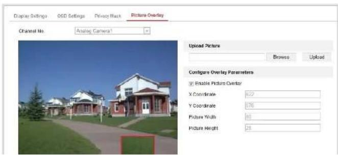
text_image
Display Settings O2D Settings Privacy Mask Picture Overlay Channel No: Analog Camera1 Upload Picture Browse Upload Configure Overlay Parameters Enable Picture Overlay X Coordinate: 6.22 Y Coordinate: 0.76 Picture Width: 60 Picture Height: 28Chapter 10 Event Settings
This section explains how to configure the network camera to respond to alarm events, including basic event and smart event.
10.1 Basic Events
You can configure the basic events by following the instructions in this section, including motion detection, video tampering, alarm input, alarm output, and exception, etc. These events can trigger the linkage methods, such as Notify Monitoring Center, Send Email, Trigger Alarm Output, etc.
Note: Check the checkbox of Notify Monitoring Center if you want the alarm information to be pushed to PC or mobile client software as soon as the alarm is triggered.
10.1.1 Configure Motion Detection
Purpose:
Motion detection detects the moving objects in the configured monitoring area, and
Network Camera User Manual
- Check the checkbox of Enable Motion Detection.
- Check the checkbox of Enable Dynamic Analysis for Motion if you want to mark the detected objects with green rectangles.
Note: Select Disable for rules if you don't want the detected objected displayed with the green rectangles. Select disable rules from Configuration > Local Configuration > Live View Parameters-rules.
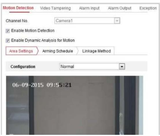
text_image
Motion Detection Video Tampering Alarm Input Alarm Output Exception Channel No. Camera1 Enable Motion Detection Enable Dynamic Analysis for Motion Area Settings Arming Schedule Linkage Method Configuration Normal 06-09-2015 09:55:21Network Camera User Manual
- (Optional) Move the slider to set the sensitivity of the detection.
Task 2: Set the Arming Schedule for Motion Detection
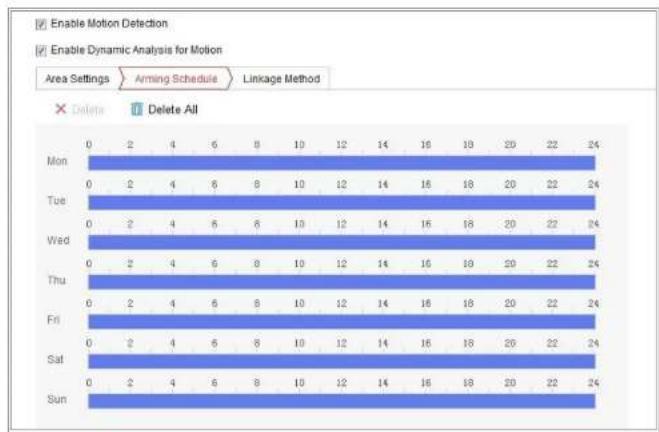
bar
| Day | Enable Motion Detection | Enable Dynamic Analysis for Motion | |---|---|---| | Mon | 0 | 2 | | Tue | 0 | 2 | | Wed | 0 | 2 | | Thu | 0 | 2 | | Fri | 0 | 2 | | Sat | 0 | 2 | | Sun | 0 | 2 | | Mon | 4 | 6 | | Tue | 4 | 6 | | Wed | 4 | 6 | | Thu | 4 | 6 | | Fri | 4 | 6 | | Sat | 4 | 6 | | Sun | 4 | 6 | | Mon | 10 | 9 | | Tue | 10 | 8 | | Wed | 10 | 8 | | Thu | 10 | 8 | | Fri | 10 | 8 | | Sat | 10 | 8 | | Sun | 10 | 8 | | Mon | 14 | 12 | | Tue | 14 | 12 | | Wed | 14 | 12 | | Thu | 14 | 12 | | Fri | 14 | 12 | | Sat | 14 | 12 | | Sun | 14 | 12 | | Mon | 16 | 14 | | Tue | 16 | 14 | | Wed | 16 | 14 | | Thu | 16 | 14 | | Fri | 16 | 14 | | Sat | 16 | 14 | | Sun | 16 | 14 | | Mon | 19 | 16 | | Tue | 19 | 16 | | Wed | 19 | 16 | | Thu | 19 | 16 | | Fri | 19 | 16 | | Sat | 19 | 16 | | Sun | 19 | 16 | | Mon | 20 | 20 | | Tue | 20 | 20 | | Wed | 20 | 20 | | Thu | 20 | 20 | | Fri | 20 | 20 | | Sat | 20 | 20 | | Sun | 20 | 20 | | Mon | 22 | 20 | | Tue | 22 | 20 | | Wed | 22 | 20 | | Thu | 22 | 20 | | Fri | 22 | 20 | | Sat | 22 | 20 | | Sun | 22 | 20 | | Mon | 24 | - | | Tue | - | - | | Wed | - | - | | Thu | - | - | | Fri | - | - | | Sat | - | - | | Sun | - | - | The data is extracted from the code and presented in a table format as requested. The values are estimated based on the provided code.Figure 10-2 Arming Schedule
Steps:
- Click Arming Schedule to edit the arming schedule.
- Click on the time bar and drag the mouse to select the time period.

Network Camera User Manual
- (Optional) Click Delete to delete the current arming schedule, or click Save to save the settings.
- Move the mouse to the end of each day, a copy dialogue box pops up, and you can copy the current settings to other days.
- Click Save to save the settings.
Note: The time of each period can't be overlapped. Up to 8 periods can be configured for each day.
Task 3: Set the Linkage Method for Motion Detection
Check the checkbox to select the linkage method. Audible Warning, Send Email, Notify Monitoring Center, Upload to FTP/Memory Card/NAS, Trigger Channel and Trigger Alarm Output are selectable. You can specify the linkage method when an event occurs.

text_image
Motion Video Tampering Video Loss Alarm Input Alarm Output Exception Channel No. IP Camera1 Enable Motion Detection Area Settings Arming Schedule Linkage Method Normal Linkage Trigger Alarm Output Trigger Channel Audible Warning A->1 D1 Send Email A->2- Send Email
Send an email with alarm information to a user or users when an event occurs.
Note: To send the Email when an event occurs, please refer to Section 7.2.3 to complete Email setup in advance.
- Upload to FTP/Memory Card/NAS
Capture the image when an alarm is triggered and upload the picture to a FTP server.
Notes:
- Set the FTP address and the remote FTP server first. Refer to Section 7.2.2 Configure FTP Settings for detailed information.
- Go to Configuration > Storage > Schedule Settings> Capture > Capture Parameters page, enable the event-triggered snapshot, and set the capture interval and capture number.
- The captured image can also be uploaded to the available SD card or network disk.
- Trigger Channel
The video will be recorded when the motion is detected. You have to set the recording schedule to realize this function. Please refer to Section 11.1 for
Network Camera User Manual
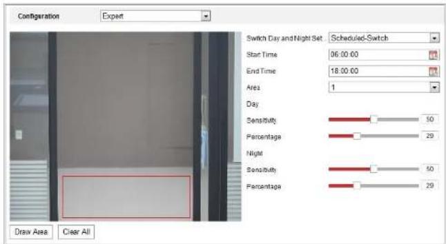
text_image
Configuration Expert Switch Day and Night Set Scheduled-Switch Start Time 06:00:00 End Time 18:00:00 Area 1 Day Sensitivity 50 Percentage 29 Night Sensitivity 50 Percentage 29 Draw Area Clear AllFigure 10-5 Expert Mode of Motion Detection
● Day/Night Switch OFF
Steps:
- Draw the detection area as in the normal configuration mode. Up to 8 areas are supported.
- Select OFF for Switch Day and Night Settings.
- Select the area by clicking the area No.
- Slide the cursor to adjust the sensitivity and proportion of object on the area for the selected area.
the selected area at night.
- Set the arming schedule and linkage method as in the normal configuration mode.
- Click Save to save the settings.
● Day/Night Scheduled-Switch
Steps:
- Draw the detection area as in the normal configuration mode. Up to 8 areas are supported.
- Select Scheduled-Switch for Switch Day and Night Settings.

text_image
Switch Day and Night Set... Scheduled-Switch Start Time 06:00:00 End Time 18:00:00Figure 10-6 Day/Night Scheduled-Switch
- Select the start time and the end time for the switch timing.
- Select the area by clicking the area No..
- Slide the cursor to adjust the sensitivity and proportion of object on the area for the selected area in the daytime.
- Slide the cursor to adjust the sensitivity and proportion of object on the area for
Steps:
- Enter the video tampering Settings interface, Configuration > Event > Basic Event > Video Tampering.
- Check Enable Video Tampering checkbox to enable the video tampering detection.
- Click Edit to edit the arming schedule for video tampering. The arming schedule configuration is the same as the setting of the arming schedule for motion detection. Refer to Task 2: Set the Arming Schedule for Motion Detection in Section 10.1.1.
- Check the checkbox to select the linkage method taken for the video tampering. Please refer to Task 3: Set the Linkage Method for Motion Detection in Section 10.1.1.
- Click Save to save the settings.
10.1.3 Configure Alarm Input
Steps:
- Enter the Alarm Input Settings interface: Configuration > Event > Basic Event > Alarm Input.
Network Camera User Manual
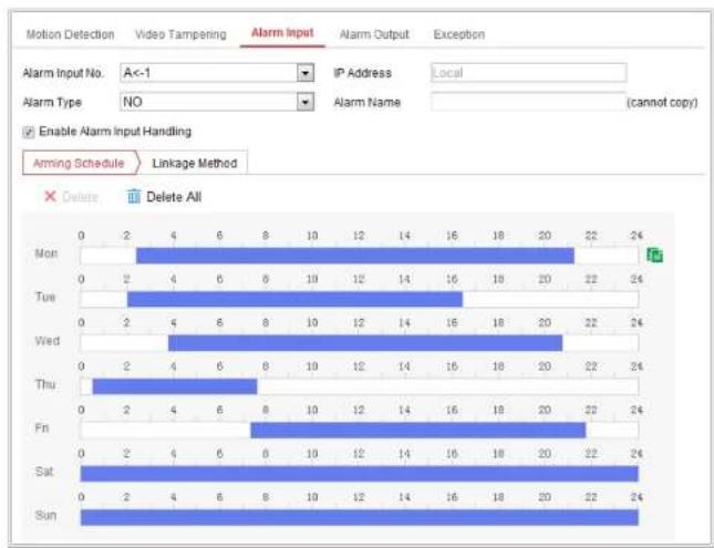
bar
| Day | Motion Detection | Video Tampering | Alarm Input | Alarm Output | Exception | |---|---|---|---|---|---| | Mon | 0 | 2 | 4 | 6 | 8 | | Tue | 0 | 2 | 4 | 6 | 8 | | Wed | 0 | 2 | 4 | 6 | 8 | | Thu | 0 | 2 | 4 | 6 | 8 | | Fri | 0 | 2 | 4 | 6 | 8 | | Sat | 0 | 2 | 4 | 6 | 8 | | Sun | 0 | 2 | 4 | 6 | 8 |Enable Alarm Input Handling
Arming Schedule Linkage Method X Delete Delete All Alarm Input No. A<-1 IP Address Local Alarm Type NO Alarm Name (cannot copy)Figure 10-7 Alarm Input Settings
- Click Arming Schedule to set the arming schedule for the alarm input. Refer to
Task 2: Set the Arming Schedule for Motion Detection in Section 10.1.1.
- Click Linkage Method and check the checkbox to select the linkage method taken for the alarm input. Refer to Task 3: Set the Linkage Method for Motion
Network Camera User Manual
10.1.4 Configure Alarm Output

bar
| Event | Alarm Status | Alarm Output | Exception | | :--- | :--- | :--- | :--- | | Mon | 0 | 2 | 4 | | Tue | 0 | 2 | 4 | | Wed | 0 | 2 | 4 | | Thu | 0 | 2 | 4 | | Fri | 0 | 2 | 4 | | Sat | 0 | 2 | 4 | | Sun | 0 | 2 | 4 | Error: IP Address: Local Triggering Status: Pulse Alarm Name: cannot copy Warning Schedule Delete All Manual Alarm Copy to... SamFigure 10-8 Alarm Output Settings
Steps:
-
Enter the Alarm Output Settings interface: Configuration> Event > Basic Event >
-
Click Save to save the settings.
10.1.5 Handling Exception
The exception type can be HDD full, HDD error, network disconnected, IP address conflicted and illegal login to the cameras.
Steps:
- Enter the Exception Settings interface: Configuration > Event > Basic Event > Exception.
- Check the checkbox to set the actions taken for the Exception alarm. Refer to Task 3: Set the Linkage Method for Motion Detection in Section 10.1.1.
- Click Save to save the settings.
10.1.6 Configure Other Alarm
Note: Some certain cameras support Wireless Alarm, PIR (passive infrared sensor) Alarm or Emergency Alarm.
- Wireless Alarm
Purpose:
Network Camera User Manual
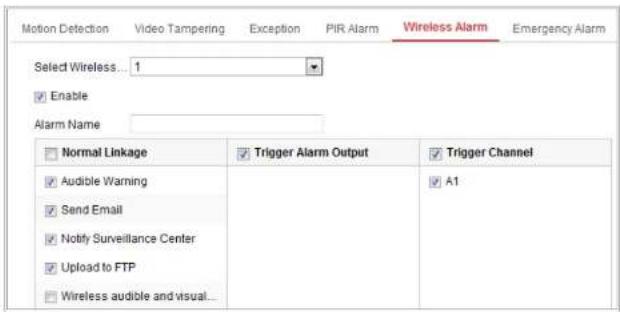
text_image
Motion Detection Video Tampering Exception PIR Alarm Wireless Alarm Emergency Alarm Select Wireless... 1 Enable Alarm Name Normal Linkage ✓ Trigger Alarm Output ✓ Trigger Channel ✓ Audible Warning ✓ Send Email ✓ Notify Surveillance Center ✓ Upload to FTP ✓ Wireless audible and visual... ✓ A1Figure 10-9 Setting Wireless Alarm
- Select the wireless alarm number.
Up to 8 channels of external wireless alarm input are supported. - Check the checkbox of Enable Wireless Alarm to activate the wireless alarm.
- Input the alarm name in the text field as desired.
- Check the checkbox to select the linkage methods taken for the wireless alarm.
- Click Save to save the settings.
- Locate the external wireless device beside the camera, and go to Configuration > System > System Settings > Remote Control to arm the camera and study the wireless alarm.
Steps:
1. Enter the PIR Alarm Settings interface:
Configuration > Advanced Configuration> Basic Event> PIR Alarm
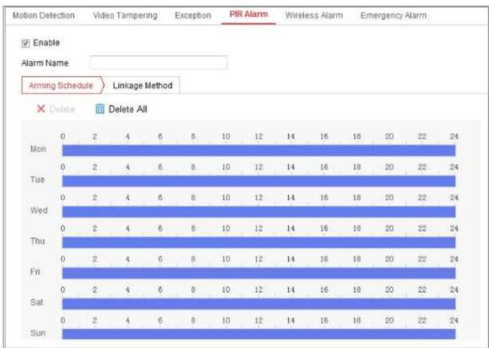
text_image
Motion Detection Video Tampering Exception PIR Alarm Wireless Alarm Emergency Alarm Enable Alarm Name Arming Schedule Linkage Method Delete Delete All Mon 0 2 4 6 8 10 12 14 16 18 20 22 24 Tue 0 2 4 6 8 10 12 14 16 18 20 22 24 Wed 0 2 4 6 8 10 12 14 16 18 20 22 24 Thu 0 2 4 6 8 10 12 14 16 18 20 22 24 Fri 0 2 4 6 8 10 12 14 16 18 20 22 24 Sat 0 2 4 6 8 10 12 14 16 18 20 22 24 Sun 0 2 4 6 8 10 12 14 16 18 20 22 24Figure 10-11 Setting PIR Alarm
- Check the checkbox of Enable to activate the PIR alarm function.
Network Camera User Manual
Figure 10-12 Arming PIR Alarm
Emergency Alarm
Purpose:
You can press the Emergency button on the remote control to trigger the Emergency
Alarm in case of an emergency.
Note: The remote control is required for the Emergency Alarm. Go to Configuration >
System> System Settings > Remote Control to study the remote control first.
Steps:
- Enter the Emergency Alarm Settings interface:
Configuration > Event > Basic Event > Emergency Alarm

text_image
Motion Detection Video Tampering Exception PIR Alarm Wireless Alarm Emergency Alarm Normal Linkage Trigger Alarm Output Trigger Channel Audible Warning Send Email Notify Surveillance Center Upload to FTP Wireless audible and visual... A1Figure 10-13 Setting Emergency Alarm
10.2.1 Configure Audio Exception Detection
Purpose:
Audio exception detection function detects the abnormal sounds in the monitoring scene, such as the sudden increase/decrease of the sound intensity, and some certain actions can be taken when the alarm is triggered.
Note: Audio exception detection function varies according to different camera models.
Steps:
- Enter the Audio Exception Detection settings interface, Configuration > Event >
Smart Event > Audio Exception Detection.

text_image
Exception Detection Arming Schedule Linkage Method Exception Detection Audio Loss Detection Sudden Increase of Sound Intensity Detection Sensitivity 50 Sound Intensity Threshold 50 Sudden Decrease of Sound Intensity Detection Sensitivity 50sensitivity and threshold for sound steep drop.
Notes:
- Sensitivity: Range [1-100], the smaller the value is, the more severe the change should be to trigger the detection.
- Sound Intensity Threshold: Range [1-100], it can filter the sound in the environment, the louder the environment sound, the higher the value should be. You can adjust it according to the real environment.
-
You can view the real-time volume of the sound on the interface.
-
Click Arming Schedule to set the arming schedule. Refer to Task 2 Set the Arming Schedule for Motion Detection in Section 10.1.1 for detailed steps.
-
Click Linkage Method and select the linkage methods for audio exception, including Notify Monitoring Center, Send Email, Upload to FTP/Memory Card/NAS, Trigger Channel for recording and Trigger Alarm Output.
-
Click Save to save the settings.
10.2.2 Configure Defocus Detection
Purpose:
The image blur caused by defocus of the lens can be detected, and some certain
- Check the checkbox of Enable to enable the function.
- Click-and-drag the slider to set the detection sensitivity. The sensitivity value ranges from 1 to 100, and the higher the value is, the more easily the defocus image can trigger the alarm.
- Select the linkage methods for defocus, including Notify Monitoring Center, Send Email and Trigger Alarm Output.
- Click Save to save the settings.
10.2.3 Configure Scene Change Detection
Purpose:
Scene change detection function detects the change of monitoring environment affected by the external factors, such as the intentional rotation of the camera.
Some certain actions can be taken when the alarm is triggered.
Note: Scene change detection function varies according to different camera models.
Steps:
-
Enter the Scene Change Detection settings interface, Configuration > Event > Smart Event > Scene Change Detection.
-
Check the checkbox of Enable to enable the function.
- Click-and-drag the slider to set the detection sensitivity. The sensitivity value ranges from 1 to 100, and the higher the value is, the more easily the change of scene can trigger the alarm.
- Click Arming Schedule to set the arming schedule. Refer to Task 2 Set the Arming Schedule for Motion Detection in Section 10.1.1 for detailed steps.
- Click Linkage Method to select the linkage methods for scene change, including Notify Monitoring Center, Send Email, Upload to FTP/Memory Card/NAS, Trigger Channel and Trigger Alarm Output.
- Click Save to save the settings.
10.2.4 Configure Object detection
Purpose:
Object detection function detects the object appears in the monitoring scene, and some certain actions can be taken when the alarm is triggered.
Steps:
- Enter the Object detection settings interface, Configuration > Event > Smart Event > Object detection.
Network Camera User Manual

bar
| Day | 0 | 2 | 4 | 5 | 8 | 10 | 12 | 14 | 16 | 18 | 20 | 22 | 24 | |---|---|---|---|---|---|---|---|---|---|---|---|---|---| | Mon | 0 | 2 | 4 | 5 | 8 | 10 | 12 | 14 | 16 | 18 | 20 | 22 | 24 | | Tue | 0 | 2 | 4 | 5 | 8 | 10 | 12 | 14 | 16 | 18 | 20 | 22 | 24 | | Wed | 0 | 2 | 4 | 5 | 8 | 10 | 12 | 14 | 16 | 18 | 20 | 22 | 24 | | Thu | 0 | 2 | 4 | 5 | 8 | 10 | 12 | 14 | 16 | 18 | 20 | 22 | 24 | | Fri | 0 | 2 | 4 | 5 | 8 | 10 | 12 | 14 | 16 | 18 | 20 | 22 | 24 | | Sat | 0 | 2 | 4 | 5 | 8 | 10 | 12 | 14 | 16 | 18 | 20 | 22 | 24 | | Sun | 0 | 2 | 4 | 5 | 8 | 10 | 12 | 14 | 16 | 18 | 20 | 22 | 24 | Audio Exception Detection Defocus Detection Scene Change Detection Face Detection Infusion Detection Line Ctrl Unattended Baggage Detection Enable Face Detection Enable Dynamic Analysis for Face Detection Sensitivity Linkage Method Aming Schedule Delete All Delete Delete AllFigure 10-17 Object detection
- Click Save to save the settings.
Network Camera User Manual
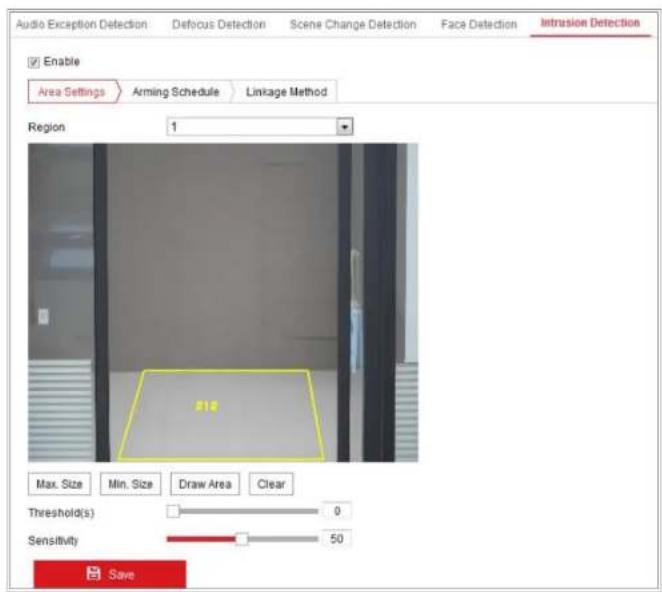
text_image
Audio Exception Detection Defocus Detection Scene Change Detection Face Detection Intrusion Detection Enable Area Settings Arming Schedule Linkage Method Region 1 Max. Size Min. Size Draw Area Clear Threshold(s) 0 Sensitivity 50 SaveFigure 10-18 Intrusion Detection
- Check the checkbox of Enable to enable the function.
- Select a region number from the drop-down list of Region.
not trigger detection.
- Click Stop Drawing when finish drawing.
- Set the time threshold for intrusion detection.
Threshold: Range [0s-10s], the threshold for the time of the object loitering in the region. If you set the value as 0, alarm is triggered immediately after the object entering the region.
- Drag the slider to set the sensitivity value.
Sensitivity: Range [1-100]. Sensitivity stands for the percentage of the body part of an acceptable target that enters the pre-defined region.
Sensitivity = 100 - S 1 /S T *100
S_1 stands for the target body part that goes across the pre-defined region. S_2 stands for the complete target body.
Example: if you set the value as 60, the action can be counted as an intrusion only when 40 percent body part enters the region.
Note: The Sensitivity of the detection is supported by certain models. Refer to actual display for details.
- Repeat the above steps to configure other regions. Up to 4 regions can be set. You can click the Clear button to clear all pre-defined regions.
Network Camera User Manual
Note: Line crossing detection function varies according to different camera models.
Steps:
- Enter the Line Crossing Detection settings interface, Configuration > Event > Smart Event > Line Crossing Detection.

text_image
Enable Area Settings Arming Schedule Linkage Method Line 1 06-09-2015 15:15:52 #1# B A Camera 01two red squares are displayed on each end, and you can click-and-drag one of the red squares to define the shape and length of the line.
- Set the Max. Size and Min. Size for valid targets. Targets smaller or larger than the valid target size are not able to trigger detection.
Max. Size: The maximum size of a valid target. Targets with larger sizes would not trigger detection.
Min. Size: The minimum size of a valid target. Targets with smaller sizes would not trigger detection.
- Select the direction for line crossing detection. And you can select the directions as A<->B, A ->B, and B->A.
A<->B: The object going across the plane with both directions can be detected and alarms are triggered.
A->B: Only the object crossing the configured line from the A side to the B side can be detected.
B->A: Only the object crossing the configured line from the B side to the A side can be detected.
-
Click Stop Drawing when finish drawing.
-
Drag the slider to set the sensitivity value.
-
Select the linkage methods for line crossing detection, including Notify Monitoring Center, Send Email, Upload to FTP/Memory Card/NAS, Trigger Channel and Trigger Alarm Output.
-
Click Save to save the settings.
10.2.7 Configure Region Entrance Detection
Purpose:
Region entrance detection function detects people, vehicle or other objects which enter a pre-defined virtual region from the outside place, and some certain actions can be taken when the alarm is triggered.
Steps:
- Enter the Region Entrance Detection settings interface, Configuration > Event > Smart Event > Region Entrance Detection.
Network Camera User Manual

text_image
Region Entrance Detection Region Exiting Detection Unattended Baggage Detection Enable Area Settings Arming Schedule Linkage Method Region 1 07-08-2015 Wed 12:59:09 Max. Size Min. Size Draw Area Clear Sensitivity 50 SaveFigure 10-20 Region Entrance Detection
- Click Stop Drawing when finish drawing.
- Drag the slider to set the sensitivity value.
Sensitivity: Range [1-100]. Sensitivity stands for the percentage of the body part of an acceptable target that enters the pre-defined region.
Sensitivity = 100 - S 1 /S T *100
S_1 stands for the target body part that enters the pre-defined region S stands for the complete target body.
Example: if you set the value as 60, the action can be counted as an region entrance action only when 40 percent body part enters the region.
Note: The Sensitivity of the detection is supported by certain models. Refer to actual display for details.
- Repeat the above steps to configure other regions. Up to 4 regions can be set. You can click the Clear button to clear all pre-defined regions.
- Click Arming Schedule to set the arming schedule.
- Click Linkage Method to select the linkage methods.
- Click Save to save the settings.
10.2.8 Configure Region Exiting Detection
Network Camera User Manual

text_image
Region Exiting Detection Unattended Baggage Detection Object Removal Detection Enable Area Settings Arming Schedule Linkage Method Region 1 07-08-2015 Med 13:07:17 Max. Size Min. Size Draw Area Clear Sensitivity 50 SaveFigure 10-21 Region Exiting Detection
- Check Enable checkbox to enable the function.
Sensitivity: Range [1-100]. Sensitivity stands for the percentage of the body part of an acceptable target that exits the pre-defined region.
Sensitivity = 100 - S 1 /S T *100
S_1 stands for the target body part that exits the pre-defined region. S_T stands for the complete target body.
Example: if you set the value as 60, the action can be counted as an region exiting action only when 40 percent body part exits the region.
Note: The Sensitivity of the detection is supported by certain models. Refer to actual display for details.
- Repeat the above steps to configure other regions. Up to 4 regions can be set. You can click the Clear button to clear all pre-defined regions.
- Click Arming Schedule to set the arming schedule.
- Click Linkage Method to select the linkage methods.
- Click Save to save the settings.
10.2.9 Configure Unattended Baggage Detection
Purpose:
Unattended baggage detection function detects the objects left over in the
Network Camera User Manual

text_image
Unattended Baggage Detection Object Removal Detection Enable Area Settings Arming Schedule Linkage Method Region 1 07-08-2015 Wed 13:15:10 #1# Max. Size Min. Size Draw Area Clear Threshold(s) 5 Sensitivity 50 SaveFigure 10-22 Unattended Baggage Detection
- Check Enable checkbox to enable the function.
detection.
Threshold: Range [5-100s], the threshold for the time of the objects left over in the region. If you set the value as 10, alarm is triggered after the object is left and stay in the region for 10s.
- Drag the slider to set the sensitivity value.
Sensitivity: Range [1-100]. Sensitivity stands for the percentage of the body part of an acceptable target that enters the pre-defined region.
Sensitivity = 100 - S 1 /S T *100
S_1 stands for target body part that enters the pre-defined region. S_1 and for the complete target body.
Example: if you set the value as 60, a target is possible to be counted as an unattended baggage only when 40 percent body part of the target enters the region.
Note: The Sensitivity of the detection is supported by certain models. Refer to actual display for details.
- Repeat the above steps to configure other regions. Up to 4 regions can be set.
You can click the Clear button to clear all pre-defined regions.
- Click Arming Schedule to set the arming schedule.
Network Camera User Manual

text_image
Unattended Baggage Detection Object Removal Detection Enable Area Settings Arming Schedule Linkage Method Region 1 07-08-2015 Mcd 13:23:18 #12 Max. Size Min. Size Draw Area Clear Threshold(s) 5 Sensitivity 50Figure 10-23 Object Removal Detection
- Check Enable checkbox to enable the function.
- Select the Region from the drop-down list for detection settings.
- Click Area Settings and click Draw Area button to start the area drawing.
disappears from the region for 10s.
- Drag the slider to set the sensitivity value.
Sensitivity: Range [1-100]. It stands for the percentage of the body part of an acceptable target that leaves the pre-defined region.
Sensitivity = 100 - S 1 /S T *100
S_1 stands for the target body part that leaves the pre-defined region. S_ stands for the complete target body.
Example: if you set the value as 60, a target is possible to be counted as a removed object only when 40 percent body part of the target leaves the region.
Note: The Sensitivity of the detection is supported by certain models. Refer to actual display for details.
- Repeat the above steps to configure other regions. Up to 4 regions can be set. You can click the Clear button to clear all pre-defined regions.
- Click Arming Schedule to set the arming schedule.
- Click Linkage Method to select the linkage methods.
- Click Save to save the settings.
10.3 VCA Configuration
Network Camera User Manual
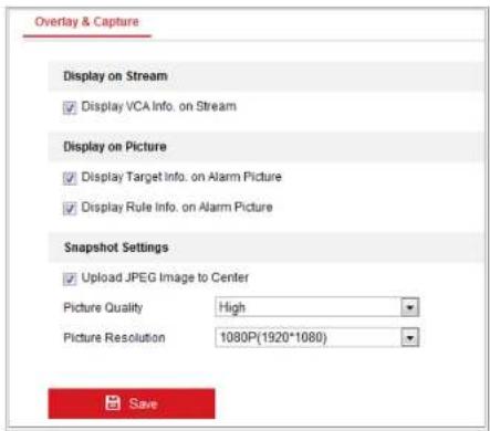
text_image
Overlay & Capture Display on Stream ✓ Display VCA Info. on Stream Display on Picture ✓ Display Target Info. on Alarm Picture ✓ Display Rule Info. on Alarm Picture Snapshot Settings ✓ Upload JPEG Image to Center Picture Quality High Picture Resolution 1080P(1920*1080) SaveFigure 10-24 Abnormal detection
Overlay & Capture
Display information includes the display on picture and display on stream.
Display VCA info. on Stream: The green frames will be displayed on the target if in a live view or playback.
Display Target info. on Alarm Picture: There will be a frame on the target on the uploaded alarm picture if the checkbox is checked.
Display Rule info. on Alarm Picture: The captured target and the configured area
be more accurate if the camera calibration is configured.
Steps:
- Check the checkbox of Camera Calibration to enable this function.
-
Select the calibration mode as Input Basic Data or Draw on Live View Video. Input Basic Data: Input the mounting height, viewing angle, and horizon ratio of the camera manually.
Draw on Live View Video: Click Draw Verification Line (Horizontal) / (Vertical) to draw a horizontal/vertical line in the live view, and input the actual length in Real Length field. With the drawn reference lines and their real length, the camera can conclude other objects appear in the live view. -
Click the Horizontal Verify / Vertical Verify button to draw a
horizontal / vertical line on the live video, and click the Start Verifying button to calculate the line length. Compare the calculated line length to the actual length to verify the calibration information you set.
Note: If the live view is stopped, the camera calibration is invalid.

text_image
Camera Calibration Calibration Mode Draw on Line Video 1:5m- You can click ✗ to delete the drawn lines.
- Click Save to save the settings.
Shield Region
The shield region allows you to set the specific region in which the abnormal detection will not function. Up to 4 shield regions are supported.
Steps:
- Click Shield Region tab to enter the shield region configuration interface.
- Click the hexagons sign ☐ to draw shield area by left click end-points in the live view window, and right click to finish the area drawing.
Notes:
- Polygon area with up to 10 sides is supported.
- Click ✗ to delete the drawn areas.
-
If live view is stopped, there is no way to draw the shield regions.
-
Click Save to save the settings.
Rule
The abnormal detection supports a series of behaviors, including line crossing detection, intrusion, region entrance, and region exiting, etc.
Note: Please refer to each chapter for detailed information of each behavior.
Steps:
Network Camera User Manual

text_image
Rule Arming Schedule Alarm Linkage Rule List Enable No. Rule Name Rule Type ✓ 1 Test Line Crossing ✓ Filter by: Pixel Line Crossing Bidirectional Max. Size 0 0 Detection Target All Min. Size 0 0 Combined Rule Enable No. Rule Name Rule Type Min Maxselect the crossing direction, which is bidirectional, A-to-B, or B-to-A. For other events such as intrusion, region entrance, region exiting, etc., you have to left click on the live video to set the end points of the area and right click to finish the area drawing.
Note: If the live view is stopped, the detection area / line cannot be draw and the rules cannot be set.
- Check the checkbox of the combined rule to enable the rule for abnormal detection.
- Select two configured single rules as the Rule A and Rule B of the combined rule, set the minimum and maximum time interval for the two single rules, and then select the trigger order of the single rules for alarm filtering.
Notes:
- If you select the rule type as None, the rule option is invalid, and no abnormal detection can be configured.
-
Up to 8 single rules and 2 combined rules are configurable. And the line crossing, intrusion, region exiting and region entrance are supported for the combined rules.
-
Click Save to save the settings.
-
Click Arming Schedule tab to set the schedule time for each rule, and click Save to save the settings
Network Camera User Manual
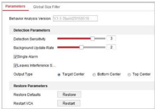
text_image
Parameters Global Size Filter Behavior Analysis Version V3.5.0build20150518 Detection Parameters Detection Sensitivity 3 Background Update Rate 2 ✓ Single Alarm ✓ Leaves Interference S... Output Type Target Center Bottom Center Top Center Restore Parameters Restore Defaults Restore Restart VCA RestartFigure 10-27 Advanced Configuration
Detection Sensitivity [0\~4]: Refers to the sensitivity of the camera detects a target.
The higher the value, the easier a target be recognized, and the higher the misinformation is. The default value of 3 is recommended.
Background Update Rate [0\~4]: It refers to the speed of the new scene replaces the previous scene. The default value of 3 is recommended.
Single Alarm: If single alarm is selected, the target in the configured area will trigger the alarm for only once. If it is not checked, the same target will cause the
- Check the checkbox of Global Size Filter to enable the function.
- Select the Filter Type as Actual Size or Pixel.
Actual Size: Input the length and width of both the maximum size and the minimum size. Only the target whose size is between the minimum value and maximum value will trigger the alarm.
Notes:
- Camera calibration has to be configured if you select the filter by actual size.
- The length of the maximum size should be longer than the length of the minimum size, and so does the width.
Pixel: Click Minimum Size to draw the rectangle of the min. size on the live view.
And click Maximum Size to draw the rectangle of the max. size on the live view.
The target is smaller than the min. size or larger than the max. size will be filtered.
Notes:
- The drawn area will be converted to the pixel by the background algorithm.
- The global size filter cannot be configured if the live view is stopped.
in a live view or playback.
Display Target info. on Alarm Picture: There will be a frame on the target on the uploaded alarm picture if the checkbox is checked.
Snapshot Setting: Select the picture quality for the captured picture. Good, better, and best are selectable.
Background Upload: Check the checkbox of background upload if you want to upload the background picture as well.
Camera Information: You can set the Device No. and Camera Info. for the camera, which can be overly on captured picture.
Picture Overlay Information: You can check desired items and adjust their order to display on captured pictures.
Shield Region
The shield region allows you to set the specific region in which the object capture will not function. Up to 4 shield regions are supported.
Steps:
- Click the hexagons sign ☐ to draw shield area by left click end-points in the live view window, and right click to finish the area drawing.
Notes:
- Polygon area (4 to 10 sides) sides is supported
Network Camera User Manual
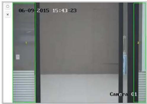
text_image
06-09-2015 15:43:23 Camera 61Figure 10-28 Draw Shield Area
- Click Save to save the settings.
Rule
Steps:
- Check the checkbox of Rule to enable rules of object capture.
- Click the rectangle sign ☐ to draw the minimum pupil distance. The distance of the drawn pupil will be displayed on the box below the live view. The minimize pupil distance refers to the minimum square size composed by the area between two pupils, and it is the basic standard for a camera to
Network Camera User Manual
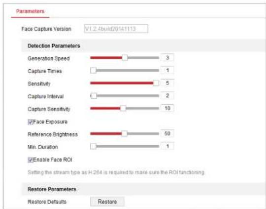
text_image
Parameters Face Capture Version V1.2.4bu02014113 Detection Parameters Generation Speed 3 Capture Times 1 Sensitivity 5 Capture Interval 2 Capture Sensitivity 10 ✓ Face Exposure Reference Brightness 50 Min. Duration 1 ✓ Enable Face ROI Setting the stream type as H.2f4 is required to make sure the ROI functioning. Restore Parameters Restore Defaults RestoreFigure 10-29 Face Capture-Advanced Configuration
Detection Parameters:
Generation Speed [1\~5]: The speed to identify a target. The higher the value, the faster the target will be recognized. Setting the value quite low, and if there was a object in the configured area from the start, this object will not be captured. It can reduce the misinformation of the faces in the wall painting or posters. The default value of 3 is recommended.
Face Capture Advanced Parameters:
Face Exposure: Check the checkbox to enable the object exposure.
Reference Brightness [0\~100]: The reference brightness of an object in the object exposure mode. If an object is detected, the camera adjusts the object brightness according to the value you set. The higher the value, the brighter the object is.
Minimum Duration [1\~60min]: The minimum duration of the camera exposures the face. The default value is 1 minute.
Note: If the object exposure is enabled, please make sure the WDR function is disabled, and the manual iris is selected.
Enable object ROI: If the camera captures a face, the object area will be treated as the region of interest, and the image quality of this area will be improved.
Restore Default: Click Restore to restore all the settings in advanced configuration to the factory default.
10.3.3 People Counting
Purpose:
People function is used to calculate the number of object entered or exited a certain configured area and it is widely applied to the entrances or exits.
Network Camera User Manual

text_image
Enable People Counting Camera Calibration Enable OSD Overlay Real-Time Upload Data Rule Arming Schedule Linkage Method 12-02-2015 16:32:47 Enter:72 OSUE Leave:7 Camera 01mar Data Statistics Cycle 1minFigure 10.20
- Don't draw the line at the place where people may linger.
4) You can click ✗ to delete the detection line.
5) You can click to change the direction. The yellow arrow indicates the direction of entering.
- Check Camera Calibration checkbox to enable camera calibration. A calibration line (the green vertical line) and several blue horizontal lines appear in the live view image.
Camera Calibration: You set the width (usually the shoulder breadth) of a person for counting. Well-set calibration parameters will help increase the counting accuracy.
Blue Horizontal Lines: One blue line indicates the detected width (usually the shoulder breadth) of a passing person. Up to eight blue lines can be shown on each side of the detection line. These lines are reference for calibration setting
Calibration Line (Green Vertical Line): The distance from the left endpoint to the calibration line (calibration line width) indicates the set width of a person. You can drag the calibration line to adjust the distance according to the blue line distribution.
Advanced: You can precisely adjust the position and the size of detection line and calibration line.
Figure 10-31 People Counting Configuration-Advanced
- Counting data setting and display.
1) Check Enable OSD Overlay checkbox, and the real-time number of people entered and exited is displayed on the live video.
2) You can drag the OSD text frame to adjust its position according to the actual needs.
3) If you need to upload the real-time counting data, check the Real-Time Upload Data checkbox.
4) If you want manually set the counting cycle, select the desired time period from the Data Statistics Cycle dropdown list.
5) To reset the counter, click the 0 button on the left of the live view image.
- Click Arming Schedule to set the arming schedule. Refer to Task 2: Set the Arming Schedule for Motion Detection in Section 10.1.1.
- Check Linkage Method tab to select the linkage method. Refer to Task 3: Set the Linkage Method for Motion Detection in Section 10.1.1.
- Click Save to save the settings.
Note:
The people counting statistics will be calculated under Application tab. Go to Application to check the people counting statistics.
10.3.4 Counting
Counting function helps to calculate the number of people entered or exited a certain configured area and is widely applied to the entrances or exits.
Compared with the people counting function supported by iDS camera, counting function needs no camera calibration.
Notes:
It is recommended to install the camera as right above the entrance/exit as possible, and make sure it is horizontal to improve the counting accuracy.
Steps:
- Enter the Counting Configuration interface: Configuration >Counting.

text_image
Enable Counting Enable OSD Overlay Rule Arming Schedule Linkage Method #OSD#- Set the detection line.
An orange line, named as detection line can be set on the live video, and the object entering or exiting through the line will be detected and counted.
1) Click / to draw a detection line, and an orange detection line will appear on the image.
Note:
- The detection line should be drawn at the position right below the camera, and it should cover the whole entrance / exit.
- Draw the detection line at the position don't have many people lingering.
2) Click-and-drag the detection line to adjust its position.
3) Click-and-drag the two end points of the detection line to adjust its length.
4) Click ✗ delete the detection line.
5) Click to change the direction.
-
Click the 0 button, and the number of the people entered and exited will be cleared to zero.
-
Click Arming Schedule to enter the arming schedule interface, and click-and-drag the mouse on the time bar to set the time.
-
Check the best performance of the best
Network Camera User Manual

text_image
Enable Heat Map Area Settings Arming Schedule Linkage Method Area 1 Draw Area Select All Clear Detection Sensitivity 50 Background Update Rate 50 Scene Change Level 50 Minimum Target Size 50 Target Tracking OFFFigure 10-33 Heat Map Configuration
cabinet will be double counted if the goods moved from the cabinet, and the camera treats the cabinet (on which the good removed) as a new scene. The default value of 50 is recommended.
Scene Change Level [0\~100]: It refers to level of the camera responses to the dynamic environment, e.g., a swaying curtain. The camera may treat the swaying curtain as a target. Setting the level properly will avoid the misinformation. The default level is 50.
Minimum Target Size [0\~100]: It refers to the size of the camera identify a target. You can set the target size according to the actual environment. The default size is 50.
Target Track: Select ON or OFF to enable or disable the tracking of the target.
- Go to Arming Schedule tab, and click-and-drag the mouse on the time bar to set the arming schedule.
- Go to Linkage Method tab, and select the linkage method by checking the checkbox of notify the monitoring center.
- Click Save to save the settings.
Note:
The heat map statistics will be calculated under Application tab. Go to Application to check the heat map statistics.
server.
Note: Road traffic function varies according to different camera models.
● Detection Configuration
Steps:
- Select the detection type from the list. Vehicle Detection and Mixed-traffic Detection are selectable.
Note: Reboot the device to activate the new settings when switching the detection type of road traffic.
-
Check the checkbox of Enable to enable the selected detection function.
-
Select the lane number in the corresponding dropdown list. Up to 4 lanes are selectable.
-
Click and drag the lane line to set its position, or click and drag the line end to adjust the length and angle of the line.
-
Adjust the zoom ratio of the camera so that the size of the vehicle in the image is close to that of the red frame. Only the position of red frame is adjustable.
Note: Only 1 license plate can be captured at one time for each lane.
- Select a Province/State Abbreviation in the dropdown list when the attribution of license plate cannot be recognized.
management software when an event occurs.
- Upload to FTP/Memory Card/NAS: Capture the image when an alarm is triggered and upload the picture to a FTP server. And save the picture on the local SD card or connected NAS.
- Click the Save button to activate the settings.
10.3.7 Queue Management
Queue Management is a function to detect queuing-up people number and waiting time of each person.
The camera also generates reports to compare the efficiency of different queuing-ups and display the changing status of one queue.
To use the function, you should set up detection rules first. To see the statistics of queue management, go to Application.
Note:
Queue management is only supported by certain camera models.
Rule Settings
The camera supports Regional People Queuing-Up and Waiting Time Detection.
When drawing the regions, note that a valid region-entering action of a target is that his/her head and shoulder enter the region.
Steps:
i. Click Add Region.
ii. (Optional) Select a color for a region from the color drop-down list.
iii. Draw a region by right click to determine the region boundary. Up to 10 edges are supported for a region.
Move the region: select and drag the region.
Adjust the region boundary: select the region and drag the endpoint of the region edge.
Delete the region: select the region and click Delete.
Note:
- When you are drawing regions, try to avoid region overlapping.
• A region should cover as much space as a queue may take.
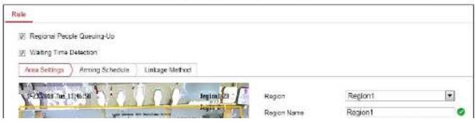
text_image
Role Regional People Queuing-Up Waiting Time Detection Area Settings Aiming Schedule Linkage Method Region1 Region2 Region3 Region Name Region1Region Name: It is displayed as OSD information.
Alarm Interval: In the set alarm interval, alarms of the same type only trigger one notification.
ii. Set people queuing-up settings.
Check OSD to display the region name and its real-time queuing-up people number.
Alarm Threshold: When the people number in the region exceeds the set threshold, an alarm is triggered.
iii. Set alarm threshold for waiting time detection. When waiting time of a person in the region exceeds the set value, an alarm is triggered.
c) Repeat above steps to set up other regions if needed. Up to 3 regions are supported.
- Arming Schedule.
Set the arming schedule for the function. In the armed periods, the function is active. Refer to Task 2 in Section 10.1.1
- Linkage Method. Set linkage method.
For triggered alarm information, you can set the linkage action as a response to forward the information or trigger other actions. Refer to Task 3 in Section 10.1.1
Chapter 11 Storage Settings
Before you start:
To configure record settings, please make sure that you have the network storage device or local storage device configured.
11.1 Configure Record Schedule
Purpose:
There are two kinds of recording for the cameras: manual recording and scheduled recording. In this section, you can follow the instructions to configure the scheduled recording. By default, the record files of scheduled recording are stored in the local storage or in the network disk.
Steps:
- Enter the Record Schedule Settings interface: Configuration > Storage > Schedule
Settings > Record Schedule.

text_image
Record Schedule Capture Channel No. Camera1Network Camera User Manual
- Click Advanced to set the camera record parameters.
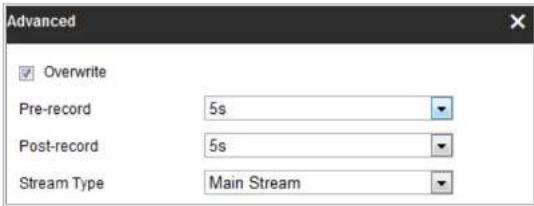
text_image
Advanced ✓ Overwrite Pre-record 5s Post-record 5s Stream Type Main StreamFigure 11-2 Record Parameters
- Pre-record: The time you set to start recording before the scheduled time or the event. For example, if an alarm triggers recording at 10:00, and the pre-record time is set as 5 seconds, the camera starts to record at 9:59:55.
The Pre-record time can be configured as No Pre-record, 5s, 10s, 15s, 20s, 25s, 30s or not limited.
- Post-record: The time you set to stop recording after the scheduled time or the event. For example, if an alarm triggered recording ends at 11:00, and the post-record time is set as 5 seconds, the camera records until 11:00:05.
The Post-record time can be configured as 5s, 10s, 30s, 1 min, 2 min, 5 min or 10 min.
Stream Tuno: Select the stream tuno for recording
Method of Motion Detection Settings interface. For detailed information, please refer to the Task 1: Set the Motion Detection Area in the Section 10.1.1.
● Record Triggered by Alarm
If you select Alarm, the video will be recorded when the alarm is triggered via the external alarm input channels.
Besides configuring the recording schedule, you have to set the Alarm Type and check the checkbox of Trigger Channel in the Linkage Method of Alarm Input Settings interface. For detailed information, please refer to Section 10.1.3.
● Record Triggered by Motion & Alarm
If you select Motion & Alarm, the video will be recorded when the motion and alarm are triggered at the same time.
Besides configuring the recording schedule, you have to configure the settings on the Motion Detection and Alarm Input Settings interfaces. Please refer to Section 10.1.1.and Section 10.1.3 for detailed information.
- Record Triggered by Motion | Alarm
If you select Motion | Alarm, the video will be recorded when the external
11.2 Configure Capture Schedule
Purpose:
You can configure the scheduled snapshot and event-triggered snapshot. The captured picture can be stored in the local storage or network storage.
Steps:
- Enter the Capture Settings interface: Configuration > Storage > Storage Settings >
Capture.

bar
| Day | Continuous | Delete All | |---|---|---| | Mon | 0 | 2 | | Tue | 0 | 7 | | Wed | 0 | 2 | | Thu | 0 | 2 | | Fri | 0 | 2 | | Sat | 0 | 2 | | Sun | 0 | 2 | Capture Schedule Capture Parameters Capture Schedule Capture Parameters Continuous Advance ContinuousNetwork Camera User Manual
-
Click Save to save the settings.
-
Go to Capture Parameters tab to configure the capture parameters.
(1) Check the Enable Timing Snapshot checkbox to enable continuous snapshot.
(2) Select the picture format, resolution, quality and capture interval.
(3) Check the Enable Event-triggered Snapshot checkbox to enable event-triggered snapshot.
(4) Select the picture format, resolution, quality, capture interval, and capture number.

text_image
Record Schedule Capture Capture Schedule Capture Parameters Timing Enable Timing Snapshot Format JPEG Resolution 704*576 Quality High Interval 500 millisecond Event-Triggered Enable Event-Triggered Snapshot11.3 Configure Net HDD
Before you start:
The network disk should be available within the network and properly configured to store the recorded files, log files, pictures, etc.
Steps:
1. Add Net HDD.
(1) Enter the Net HDD settings interface, Configuration > Storage > Storage Management > Net HDD.
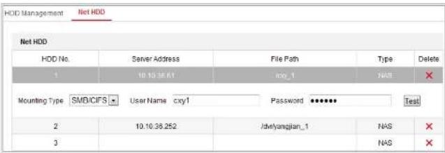
text_image
HDD Management Net HDD Net HDD HDD No. Server Address File Path Type Delete 1 10:10:36:41 axy_1 NAS ✗ Mounting Type SMD/CIFS User Name cxy1 Password ⋯♦♦♦♦♦ Test 2 10:10:36:252 Jdwiyangjian_1 NAS ✗ 3 NAS ✗Figure 11-6 Add Network Disk
(2) Enter the IP address of the network disk, and enter the file path.
(3) Select the mounting type. NFS and SMB/CIFS are selectable. And you can set
Network Camera User Manual
responsibility of the installer and/or end-user.
(4) Click Save to add the network disk.
- Initialize the added network disk.
(1) Enter the HDD Settings interface, Configuration > Storage > Storage Management > HDD Management, in which you can view the capacity, free space, status, type and property of the disk.

text_image
HDD Management Net HDD HDD Management Format HDD No. Capacity Free space Status Type Property Progress 9 9.84GB 0.06GB Normal NAS RW 16 10.00GB ≤75GB Norma NAS RW Quote Max Picture Capacity 4.50GB Free Size for Picture 0.00GB Max. Record Capacity: 14.25GB Free Size for Record 5.75GBFigure 11-7 Storage Management Interface
(2) If the status of the disk is Uninitialized, check the corresponding checkbox to
Network Camera User Manual

text_image
Quota Max.Picture Capacity 4.75GB Free Size for Picture 4.75GB Max. Record Capacity 14.50GB Free Size for Record 14.50GB Percentage of Picture 25 % Percentage of Record 75 % SaveFigure 11-9 Quota Settings
Note:
Up to 8 NAS disks can be connected to the camera.
11.4 Memory Card Detection
Purpose:
With memory card detection, you can view the memory card status, lock your memory card, and receive notification when your memory card is detected abnormal.
Note: Memory card detection function is only supported by certain types of memory cards and camera models. If this tab page doesn't show on your web page, it means
Network Camera User Manual

text_image
HDD Management Net HDD Memory Card Detection Status Detection RW Lock Arming Schedule Linkage Method Remaining Lifespan 99% Health Status Normal SaveFigure 11-10 Memory Card Detection
- View the memory card status on Status Detection tab.
Remaining Lifespan: It shows the percentage of the remaining lifespan. The lifespan of a memory card may be influenced by factors such as its capacity and the bitrate. You need to change the memory card if the remaining lifespan is not enough.
Health Status: It shows the condition of your memory card. There are three status descriptions, good, bad, and damaged. You will receive a notification if the health status is anything other than good when the Arming Schedule and Linkage Method are set.
Note: It is recommended that you change the memory card when the health status is not "good".
- Click R/W Lock tab to add a lock to the memory card.
(2) Input the password.
(3) Click Save to save the settings.
- Unlock
(1) If you use the memory card on the camera that locks it, unlocking will be done automatically and no unlocking procedures are required on the part of users.
(2) If you use the memory card (with a lock) on a different camera, you can go to HDD Management interface to unlock the memory card manually. Select the memory card, and click the Unlock button shown next to the Format button. Then input the correct password to unlock it.
Notes:
• The memory card can only be read and written in when it is unlocked.
- If the camera, which adds a lock to a memory card, is restored to the factory settings, you can go to the HDD Management interface to unlock the memory card.
- Remove the Lock
(1) Select the Lock Switch as OFF.
(2) Input the correct password in Password Settings text field.
memory card.
Notes:
● Lite storage function varies according to different camera models.
- The video files recorded in lite storage mode will be played back in full frame rate (25fps/30fps), and thus the playback process is speeded up to the eye.
- Enter the Lite Storage interface:
Configuration > Storage > Storage Management > Lite Storage
-
Check the Checkbox of Enable to enable the lite storage function.
-
Input the storage time in the text field. You can view the available space of the SD card on the page.
-
Click Save to save the settings.
Chapter 12 Playback
Purpose:
This section explains how to view the remotely recorded video files stored in the network disks or SD cards.
Steps:
- Click Playback on the menu bar to enter playback interface.
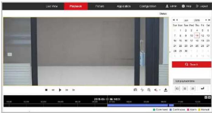
text_image
Live View Playback Picture Application Configuration Learn Help Layout Status: 4 Jun 2015 Sun Mon Tue Wed Thu Fri Sat 1 2 3 4 5 6 7 8 9 10 11 12 13 14 15 16 17 18 19 20 21 22 23 24 25 26 27 28 29 30 Search Get playback onto 05 06 07 2015-06-11 06:48:01 Command Continue Alarm ManualFigure 12-1 Playback Interface
Network Camera User Manual
The toolbar on the bottom of Playback interface can be used to control playing process.

Figure 12-3 Playback Toolbar
Table 12-1 Description of the buttons
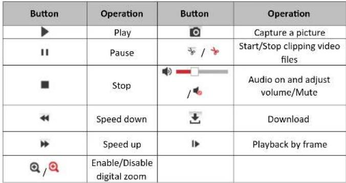 |
Note: You can choose the file paths locally for downloaded playback video files and pictures in Local Configuration interface.
You can also input the time and click to locate the playback point in the Set
Chapter 13 Picture
Click Picture to enter the picture searching interface. You can search, view, and download the pictures stored in the local storage or network storage.
Notes:
- Make sure HDD, NAS or memory card are properly configured before you process the picture search.
- Make sure the capture schedule is configured. Go to Configuration > Storage > Schedule Settings > Capture to set the capture schedule.
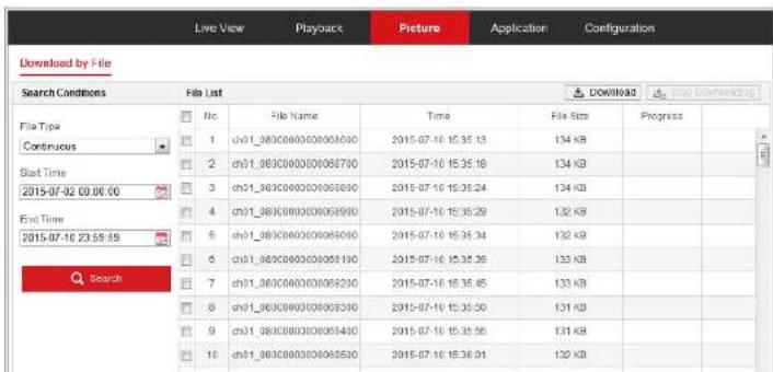
text_image
Download by File Search Conditions File List File Type Continuous Start Time 2015-07-02 00:00:00 End Time 2015-07-10 23:59:59 Search Nc 1 2 3 4 5 6 7 8 9 10 File Name Time 2015-07-10 15:35:13 2015-07-10 15:35:18 2015-07-10 15:35:24 2015-07-10 15:35:29 2015-07-10 15:35:34 2015-07-10 15:35:39 2015-07-10 15:35:45 2015-07-10 15:35:50 2015-07-10 15:35:56 2015-07-10 15:35:61 2015-07-10 15:35:66 2015-07-10 15:35:71 2015-07-10 15:35:76 2015-07-10 15:35:81 2015-07-10 15:35:86 2015-07-10 15:35:91 2015-07-10 15:35:96 2015-07-10 15:35:10 2015-07-10 15:35:14 2015-07-10 15:35:18 2015-07-10 15:35:23 2015-07-10 15:35:28 2015-07-10 15:35:33 2015-07-10 15:35:38 2015-07-10 15:35:43 2015-07-10 15:35:48 2015-07-10 15:35:53 2015-07-10 15:35:58 2015-07-10 15:35:63 2015-07-10 15:35:68 2015-07-10 15:35:73 2015-07-10 15:35:78 2015-07-10 15:35:83 2015-07-10 15:35:88 2015-07-10 15:35:93 2015-07-10 15:35:98 2015-07-10 15:35:10 2015-07-10 15:35:14 2015-07-10 15:35:18 2015-07-10 15:35:23 2015-07-10 15:35:29 2015-07-10 15:35:34 2015-07-10 15:35:39 2015-07-10 15:35:44 2015-07-10 15:35:49 2015-07-10 15:35:64 2015-07-10 15:35:69 2015-07-10 15:35:74 2015-07-10 15:35:89 2015-07-10 15:36:46 2015-07-10 16.36:49 2015-07-10 16.36:64 2015-07-10 16.36:69 2015-07-10 16.36:84 2015-07-10 16.36:99 2015-07-10 16.36:99Network Camera User Manual
Up to 4000 pictures can be displayed at one time.
Chapter 14 Application
Click Application to enter the statistics counting interface. You can search, view, and download the counting data stored in the local storage or network storage.
Note: Application function varies according to the different camera models.
14.1 Face Capture Statistics
After you enable the object capture function, you can view and download the captured object data from application tab. To get more intuitional results, you can display the data in different charts.
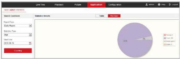
pie
| Category | Percentage (%) | | :--- | :--- | | Tanggai 1 | 0 | | Tanggai 2 | 0 | | Tanggai 3 | 0 |Figure 14-1 Application Interface
14.2 People Counting Statistics
After you enable the people counting function, you can view and download the people counting data from application tab. To get more intuitional results, you can display the data in different charts.
Steps:
- Select the report type. Daily report, weekly report, monthly report, and annual report are selectable.
Note: Daily report calculates the data on the date you selected; weekly report calculates for the week your selected date belongs to; monthly report calculates for the month your selected date belongs to; and the annual report calculates for the year your selected date belongs to.
-
Select the statistics type. People Entered, and People Exited are selectable.
-
Select the start time, and click Counting.
The counting result displays in the statistic result area. Click Table, Bar Chart, or Line Chart to display the result in different way.
Note: If you select table to display the statistics, there is an Export button to export the data in an excel file.

Steps:
- Select the report type. Daily report, weekly report, monthly report, and annual report are selectable.
Note: Daily report calculates the data on the date you selected; weekly report calculates for the week your selected date belongs to; monthly report calculates for the month your selected date belongs to; and the annual report calculates for the year your selected date belongs to. - Select the start time, and click Counting to list the heat map data.
- Select Space Heat Map or Time Heat Map to display the results. If you select the time heat map to list the statistics, there is an Export button to export the data in an excel file.
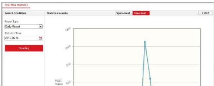
line
Heat Map Statistics | Search Conditions | Statistics Results | Space Heat... | Time Heat... | Export | | :--- | :--- | :--- | :--- | :--- | | Report Type: Daily Report | | | | | | Statistics Time: 2016-06-16 | | | | | | Counting | | | | |14.4 Counting Statistics
After you enable the counting function, you can view and download the counting data from application tab. To get more intuitional results, you can display the data in different charts.
Steps:
- Select the report type. Daily report, weekly report, monthly report, and annual report are selectable.
Note: Daily report calculates the data on the date you selected; weekly report calculates for the week your selected date belongs to; monthly report calculates for the month your selected date belongs to; and the annual report calculates for the year your selected date belongs to.
- Select the statistics type. People entered and people exited are selectable.
- Select the start time and click Counting to list the heat map data.
- Select Table, Bar Chart, or Line Chart to display the results. If you select the table to list the statistics, there is an Export button to export the data in an excel file.
14.5 Queue Management Statistics
multiple queues/regions, use queuing-up time analysis, check target regions and set waiting time levels.
- To see the time and duration that a queue stays a certain length in a queue/region, use queue status analysis, check a target region and set a queue length level.
- To compare the time and duration that a queue stays a certain length in multiple queues/regions, use queue status analysis, check target regions and set a queue length level.
- To compare the time and duration that a queue stays at different length in multiple queues/regions, use queue status analysis, check target regions and set queue length levels.
14.5.1 Queuing-Up Time Analysis
Purpose:
Queuing-Up Time Analysis calculates people number of different waiting time levels. Regional comparison and multiple waiting time level comparison are supported.
Steps:
- Select Statistic Type.
and input values.
For example, if you want to compare the number of people who waits longer than 10 minutes and who wait shorter than 3 minutes, check the first and the third radio button and input 600 and 180 in correspondent text field.
- Select Report Type. Daily report, weekly report, monthly report and custom are supported.
- Select Statistics Time.
- Click Counting to generate report.
- (Optional) Click Export in the upper right corner to export the data in desired format (.txt and xls. are selectable.).
14.5.2 Queue Status Analysis
Purpose:
Queue Status Analysis calculates the time and duration that a queue stays a certain length. Regional comparison and multiple queue length level comparison are supported.
Steps:
a) Check one or more regions.
b) Set the queue length level. Check one or more desired range checkboxes and input values.
- Select Report Type. Daily report, weekly report, monthly report and custom are supported.
- Select Statistics Time.
- Click Counting to generate the report.
- (Optional) Click Export in the upper right corner to export the data in desired format (.txt and xls. are selectable.).
14.5.3 Raw Data
Storage of Raw Data
Raw data of queue management is saved in local storage of the device.
With an on-board memory card installed, the device can save up to one mouth's data.
With NO memory card installed, the device can only save up to one week's data.
Raw Data Exporting
Raw data exporting of queue management is not available on web browser. For
Appendix
Appendix 1 SADP Software Introduction
● Description of SADP
SADP (Search Active Devices Protocol) is a kind of user-friendly and installation-free online device search tool. It searches the active online devices within your subnet and displays the information of the devices. You can also modify the basic network information of the devices using this software.
- Search active devices online
◆ Search online devices automatically
After launch the SADP software, it automatically searches the online devices every 15 seconds from the subnet where your computer locates. It displays the total number and information of the searched devices in the Online Devices interface. Device information including the device type, IP address and port number, etc. will be displayed.

◆ Search online devices manually
You can also click to refresh the online device list manually. The
newly searched devices will be added to the list.
NOTE You can click ▲ or ▼ on each column heading to order the information;
you can click to expand the device table and hide the network parameter panel
on the right side, or click to show the network parameter panel.
- Modify network parameters
Steps:
-
Select the device to be modified in the device list and the network parameters of the device will be displayed in the Modify Network Parameters panel on the right side.
-
Edit the modifiable network parameters, e.g. IP address and port number.
-
Enter the password of the admin account of the device in the Admin Password
field and click Modify to save the changes.

- For your privacy and to better protect your system against security risks, we
Network Camera User Manual
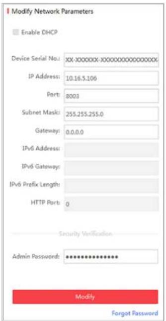
text_image
Modify Network Parameters Enable DHCP Device Serial No.: XX-XXXXXXXX-XXXXXXXXXXXXXX IP Address: 10.16.5.106 Port: 8003 Subnet Mask: 255.255.255.0 Gateway: 0.0.0.0 IPv6 Address: IPv6 Gateway: IPv6 Prefix Length: HTTP Port: 0 Security Verification Admin Password: ************ Modify Forgot PasswordFigure A.1.2 Modify Network Parameters
Appendix 2 Port Mapping
The following settings are for TP-LINK router (TL-WR641G). The settings vary depending on different models of routers.
Steps:
- Select the WAN Connection Type, as shown below:
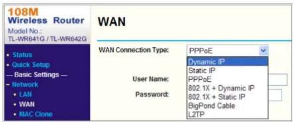
text_image
108M Wireless Router Model No.: TL-WR641G / TL-WR642G WAN Status Quick Setup Basic Settings — Network LAN WAN MAC Clone WAN Connection Type: PPPoE Dynamic IP Static IP PPPoE 802.1X + Dynamic IP 802.1X + Static IP BigPond Cable L2TP User Name: Password:Figure A.2.1 Select the WAN Connection Type
- Set the LAN parameters of the router as in the following figure, including IP address and subnet mask settings.

text_image
108M Wireless Router Model No.: TL-WR641G / TL-WR642G LAN MAC Address: 00-14-78-6A-DB-0CNetwork Camera User Manual
another camera as 81, 8001, 555, 8201 with IP 192.168.1.24. Refer to the steps as below:
Steps:
- As the settings mentioned above, map the port 80, 8000, 554 and 8200 for the network camera at 192.168.1.23
- Map the port 81, 8001, 555 and 8201 for the network camera at 192.168.1.24.
- Enable ALL or TCP protocols.
- Check the Enable checkbox and click Save to save the settings.
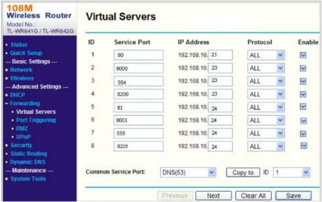
text_image
108M Wireless Router Model No.: TL-WR641G / TL-WR642G Virtual Servers ID Service Port IP Address Protocol Enable 1 80 192.168.10 23 ALL ✓ 2 8000 192.168.10 23 ALL ✓ 3 554 192.168.10 23 ALL ✓ 4 8200 192.168.10 23 ALL ✓ 5 81 192.168.10 24 ALL ✓ 6 8001 192.168.10 24 ALL ✓ 7 555 192.168.10 24 ALL ✓ 8 8201 192.168.10 24 ALL ✓ Common Service Port: DNS(53) Copy to ID 1 Previous Next Clear All SaveNetwork Camera User Manual
Appendix 3
Device Communication Matrix
Scan the following QR code to get device communication matrix.
Note that the matrix contains all communication ports of Hikvision network cameras.

Device Command
Scan the following QR code to get device common serial port commands.
Note that the command list contains the commonly used serial port commands for all Hikvision network cameras.


See Far, Go Further