
YV-3910M - Musical instrument YAMAHA - Free user manual and instructions
Find the device manual for free YV-3910M YAMAHA in PDF.

| Product Type | Vibraphone |
| Model | YV-3910M |
| Range | C3 to F6 (3.5 octaves) |
| Bars Material | Aluminum Alloy, Glossy Gold Finish |
| Bar Dimensions | Graduating from 1-1/8" to 2-1/5" wide, 1/2" thick |
| Pitch | A = 442 Hz |
| Drive Unit | YVM-300 Pause-Memory Controller, 25-145 rpm |
| Power Supply | Yamaha AC Adapter PA-130 (DC 12V, 1A) or PA-D015 (DC 15V, 1A) |
| Power Consumption | 2.9 W (PA-130), 3.6 W (PA-D015) |
| Dimensions (L x W) | 164 x 83 cm (64-5/8" x 32-5/8") |
| Height Adjustment Range | 86-94 cm (33-7/8" - 37") |
| Weight | 61 kg (134.5 lbs) |
| Casters | Oversized 4" high casters |
| Sustain Damper | Adjustable pedal with wire clip for half or open damper |
| Pause Memory Function | Stops fan in the same position each time |
| Assembly | Requires at least 2 persons; foldable for transport |
| Safety Features | Stopper casters, warning against moving on slopes |
Frequently Asked Questions - YV-3910M YAMAHA
User questions about YV-3910M YAMAHA
0 question about this device. Answer the ones you know or ask your own.
Ask a new question about this device
Download the instructions for your Musical instrument in PDF format for free! Find your manual YV-3910M - YAMAHA and take your electronic device back in hand. On this page are published all the documents necessary for the use of your device. YV-3910M by YAMAHA.
USER MANUAL YV-3910M YAMAHA
natural_image
Line drawing of a YAMAHA instrument with multiple cylindrical components and support beams (no text or symbols)Русский / English
足手叫1中文
SPECIAL MESSAGE SECTION
This product utilizes an external power supply (adapter). DO NOT connect this product to any power supply or adapter other than one described in the manual, on the name plate, or specifically recommended by Yamaha.
WARNING: Do not place this product in a position where anyone could walk on, trip over, or roll anything over power or connecting cords of any kind. The use of an extension cord is not recommended! If you must use an extension cord, the minimum wire size for a 25° cord (or less) is 18 AWG. NOTE: The smaller the AWG number, the larger the current handling capacity. For longer extension cords, consult a local electrician.
This Product should be used only with the components supplied or; a cart, rack, or stand that is recommended by Yamaha. If a cart, etc., is used, please observe all safety markings and instructions that accompany the accessory product.
SPECIFICATIONS SUBJECT TO CHANGE: The information contained in this manual is believed to be correct at the time of printing. However, Yamaha reserves the right to change or modify any of the specifications without notice or obligation to update existing units.
NOTICE: Service charges incurred due to lack of knowledge relating to how a function or effect works (when the unit is operating as designed) are not covered by the manufacturer's warranty; and are therefore the owners responsibility. Please study this manual carefully and consult your dealer before requesting service.
Disposal Notice: Should this Product become damaged beyond repair, or for some reason its useful life is considered to be at an end, please observe all local, state, and federal regulations that relate to the disposal of products that contain lead, batteries, plastics, etc. If your dealer is unable to assist you, Please contact Yamaha directly.
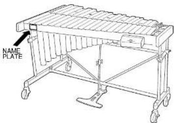
NAME PLATE LOCATION: The name Plate is located on the player side of the product. The model number, serial number, power requirements, etc., are located on this plate. You should record the model number, serial number, and the date of purchase in the spaces provided below and retain this manual as a permanent record of your purchase.
Model
Information for Users on Collection and Disposal of Old Equipment and used Batteries

These symbols on the products, packaging, and/or accompanying documents mean that used electrical and electronic products and batteries should not be mixed with general household waste.
For proper treatment, recovery and recycling of old products and used batteries, please take them to applicable collection points, in accordance with your national legislation and the Directives 2002/96/EC and 2006/66/EC.
By disposing of these products and batteries correctly, you will help to save valuable resources and prevent any potential negative effects on human health and the environment which could otherwise arise from inappropriate waste handling.
For more information about collection and recycling of old products and batteries, please contact your local municipality, your waste disposal service or the point of sale where you purchased the items.
[For business users in the European Union]
If you wish to discard electrical and electronic equipment, please contact your dealer or supplier for further information.


Cd
[Information on Disposal in other Countries outside the European Union]
These symbols are only valid in the European Union. If you wish to discard these items, please contact your local authorities or dealer and ask for the correct method of disposal.
Note for the battery symbol (bottom two symbol examples):
This symbol might be used in combination with a chemical symbol. In this case it complies with the requirement set by the Directive for the chemical involved.
Please obey the following instructions in order to use your vibraphone in a safe manner. Particularly in the case of children, a responsible adult should provide proper instruction on how to properly use and treat the instrument before use.
In order to prevent fire, electric shock, and injury, make sure that all precautions described below are obeyed.
About the icons
Icons are used in this "Safety Precautions" section to promote the safe use of this instrument, and to protect you and others from harm and properly damage. Please fully understand the meaning of the icons before reading the instructions.

This icon urges caution (includes dangers and warnings).

This icon indicates actions that are prohibited.

For example: Do not dismantle.

This icon indicates special instructions that should be strictly followed.

For example: Unplug the electric plug from the outlet

Warning
Disregard of the warnings denoted with this mark and misuse of the product can lead to death or serious injury.

Before using the vibraphone, please thoroughly read the following instructions and the Owner's Manual.

Do not dismantle or modify the vibraphone's controller or driver. Doing so can cause fire or electrical shock.

Repairs or part replacement should not be attempted unless instructions are provided in the manual.

Do not use or store the instrument in any of the following locations. Doing so can cause fire or electrical shock.
• In places subject to high temperatures (near a heating device or in direct sunlight, etc.).
- In places where the instrument may be exposed to moisture (bathroom, on wet floors, etc.) and excessive humidity.
- In places where the instrument may be exposed to rain.
• In places with excessive dust

Never put foreign objects (combustible objects, coins, wire, etc.) or liquids (water, juice, etc.) in the drive unit. Doing so can cause fire and electric shock.

If one of the following occurs, turn off the power, unplug the AC adapter and request repair as soon as possible.
- If the AC adapter or power cord becomes damaged.
- If foreign objects or liquids have gotten into the drive unit.
• If the drive unit gets wet (rain, etc.). - If the drive unit operates abnormally or is broken.

Never place the instrument on a sloping or unstable surface or platform, etc. Doing so can cause the instrument to fall over resulting in injury.

When moving the instrument on its casters, only move across smooth, flat surfaces. Hold the instrument by its side frames and push forward slowly
Safety Precautions

Caution
Disregard of the warnings denoted with this mark, or misuse of the product can result in injury or property damage.

Do not use the instrument in locations with poor ventilation.

Never pull on the cord when disconnecting the AC adapter from the outlet. Always hold the AC adapter when connecting or disconnecting the power.

Always disconnect the AC adapter from the outlet when the instrument is not used for any extended period of time.

Always use an AC adapter that meets YAMAHA specifications. The use of any other AC adapter may cause damage.

Never place your hands or feet underneath the pedal. Doing so can result in pinched hands or feet.

Never touch the rotating fans. Doing so can result in pinched fingers, etc.

Never use the mallets for anything other than playing the instrument. Doing so can result in injury or accidents. Do not allow children to use the mallets in any way that may pose a danger to themselves or others.

Lock the stoppers on the casters when the instrument is not in use.

When adjusting the playing surface height (described on page 29), make sure that the procedure is performed by at least two persons. Attempting to adjust the height alone can result in the instrument overturning and create a danger.

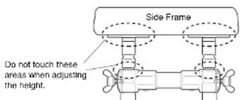
Never touch the areas shown below when adjusting the height. Doing so can result in pinched hands. Make sure to hold the side frame when making height adjustments.

Tighten bolts securely alter determining the desired height. Using the instrument with loose bolts can result in the instrument collapsing, noise, or other troubles. Tighten the bolts occasionally.
PRECAUTIONS
Please read the following instructions carefully before using your vibes.
● Do Not Use Outdoors
Avoid using the instrument outdoors. Avoid exposure to rain or moisture.
- Keep This Manual for Future Reference
After reading, make sure to keep the manual in a safe place.
● Handling
Do not use hard orchestra bell mallets or other hard objects on your vibes. The resulting dents or scratches in the tone bars could impair the sound.
The shipping carton of your YV-4110/3910/3710 should contain the parts shown below.
Before assembling the instrument, confirm that all parts are included as listed.
* In the event that a part is missing, please contact the shop where the instrument was purchased.
① Natural Tone Bars x 1
③ Resonators (Natural Tone Side) x 1
④ Resonators (Accidental Tone Side) x 1
⑧ Rail (2) : Player Side x 1
⑭ Synchro Belt (Fan Belt) x 2
YV-4110/3910/3710
The YV-4110's/3910's/YV-3710's large parts are designed to either divide or collapse. When the instrument is broken down, its compact size makes it easy to transport and storage requires a minimum amount of space.
The rails fold in from the center.
● Перекладины
The pedal stay divides into left and right sections and the pedal itself.
Loosen the 2 wing nuts and remove the stays from the pedal attachment.
● Опора педали
The sustain damper divides into 2 sections. Loosen the bolt and separate left and right sections.
● Демпфер
For safety, assembly should be performed by at least 2 persons in a location with sufficient space.
We recommend to you to assemble the instrument on a soft rug or carpet.
1 Connect the large and the small leg using the reinforcement stay and pedal stay.
Before proceeding, make sure that the slide leg fixing bolts of the large and small leg are securely fastened.
1-2 Insert the pedal stay with its notch facing up into the lower joint of the large leg as far as it will go (aligning the notch with the fixing bolt) and tighten the fixing bolt securely.
* The hole next to the notch serves as a reference for the correct insertion position.
1-3 Connect the other ends of the pedal stay with the small leg in the same way.
1-4 Loosen the slant shaft bolt, extend the shaft and insert the shaft end into the leg joint. With the notch aligned with the fixing bolt (the same as in the pedal stay assembly) tighten the fixing bolt securely.
1-5 Connect the other side slant shaft with the small leg in the same way.
2 Insert the rails (1) through (4) into the legs.
2-1 First, insert rail (2).
* Do not insert the rail one side at a time, but at first alternately push in the left and right sides little by little, after which the rail can be pushed down until it stops.
2-2 Next, securely insert the rails (3), (1) and (4), in this order.
3 Attach the sustain damper.
3-1 Turn the fixing bolt (damper arm axle) of the damper arm attachment counterclockwise until the axle has fully disappeared in the attachment hole.
2 Align the damper arm hole with the damper arm axle.
3 Turn the fixing bolt of the damper arm attachment clockwise to insert the damper arm axle into the sustain damper arm.
Align the holes in both ends of the damper spring stopper with the protrusions of the fittings on the bottom surfaces of rails (2) and (3) and insert.
3-2
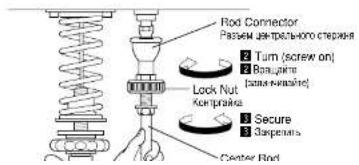
1 Loosen the center rod fixing bolts to extend the center rod.
2 Connect the center rod with the fitting of the rod connector by firmly holding the center rod while turning the rod connector.
3 Tighten the rod connector until it stops, and then secure with the lock nut.
4 Attach the resonators.
4-1 Insert the resonators from underneath the frame and rest the high sound side and then the low sound side onto the resonator holders (rubber). * Make sure not to confuse the natural tone side and accidental tone side resonators. * Take care not to bump the resonators against the legs etc.
5 Set the tone bars.
5-1 (Refer to the illustration of step 3-3) Raise the pedal until the knuried part is fully retracted, and fix the center rod by tightening the center rod fixing bolt.
5-2 Engage the rail clamp on rail (2) and rail (3) with rail (1) and rail (4), respectively.
5-3 Hold the pedal depressed to keep the sustain damper lowered, and then carefully set the tone bars. Align each tone bar individually, and hook its string onto the corresponding post. Confirm that all strings are secured to their posts, and then hook the two springs at the low sound side into each other.
6 Attach the driver.
6-1 Loosen the fixing bolts at the bottom of rails (2) and (3) on the high sound side, and slide both fittings in the direction of the low sound side.
6-2 Fully insert the driver mount into the support fitting.
6-3 Slide the fittings moved in step 6-1 back in the direction of the high sound side. Engage the two side mounts on the driver securely with the fittings, and then tighten the fixing bolts to fasten the driver. * Set the driver so that the pulleys on either side are
7-1 Loosen the fixing bolt, slide out the controller hanger and hang the controller on the hanger. Return the controller hanger to its proper position and tighten the fixing bolt.
8 Connect the driver with the controller.
B-1 Connect the MOTOR IN terminal of the driver with the MOTOR OUT terminal of the controller using the supplied 8P DIN cable*. To connect align the arrow mark ( ) on the plug with the screw next to the jack.
9 Set the synchro belts (fan belts)*.
9-1 First, wrap the synchro belt around the driver pulley and then carefully slide it over the fan side pulley.
Note For Service Personnel
If the belt cannot be mounted because the distance between the pulleys is too wide, or the belt slips due to a too narrow pulley distance, loosen the two driver positioning screws (see illustration below) to adjust the pulley distance (belt tension). Tighten the screws securely after adjustment.
10-1 Pedal Stroke Adjustment
Loosen the center rod fixing bolts to adjust the protruding length of the center rod to the desired pedal stroke, and relighten the bolts. The recommended stroke (distance between pedal and floor) is 9/16" to 13/16" (1.5 to 2 cm).
10 РЕГУЛИРОВКИ
10-2 Wire Clip Adjustment
For shipment the wire clip is Initially set at a low position for packing reasons. For normal use this clip should be adjusted as follows: With the pedal released loosen the fixing bolt of the wire clip, shift the clip up until distance A in the illustration below is 1/16" to 1/8" (1 to 3 mm), and lighten the wing bold in this position. The clip also allows setting the instrument to "half sustain damper" (slight continuous damper effect) or "open damper" by changing its position accordingly. * To set to "open damper" depress the damper ped-al fully to keep the damper open, and set the wire clip to the highest position to lock the damper.
10-3 Damper Spring Adjustment
The damper effect (its pressing force on the tone bars) and the pedal force can be increased by turning the spring adjustment wheel counterclockwise.
Tone Bar Height Adjustment
This adjustment should always be performed by at least 2 persons.
To adjust the height of the tone bars, first remove the synchro belt, driver, controller, tone bars, and resonators in the reverse order of steps [9], 8, [7, [6], [5], and [4], and loosen the center rod fixing bolts.
Loosen the slide leg fixing bolts on the high and low sound sides, while supporting the frame ends by hand.
Lift the frame ends to the desired height and then securely tighten each fixing bolt, aligning it with the corresponding notch of the slide leg. Bolt and notch are aligned when the next higher notch is flush with the upper leg flange.
10-4
Also, accessible, contains both sets built and connect to
■ Power Supply
Prepare the supplied AC adapter.
* Make sure to use the supplied AC adapter. Use of different adapters may cause damage not covered by the warranty.
1 Connect the small plug of the AC adapter to the DC 12-15V IN jack on the controller.
2 Plug the AC adapter into a power outlet.
■ Источник питания
■ PAUSE MEMORY FUNCTION SETTING (YV-4110/3910/3710 only)
The YV-4110/3910/3710 are equipped with a PAUSE MEMORY FUNCTION which stops the fan always in exactly the same position when it is turned off (no vibrato applied).
After connection to an AC outlet, set the PAUSE MEMORY to the desired fan stop position as follows:
Turn the controller power ON.
^2 Press the START/STOP button once to start the fan, and then press the START/STOP button once again to stop the fan.
3 Remove the synchro belt by sliding it off the fan side nut.
The shipping carton of your YV-2700/2700G/520 should contain the parts shown below.
Before assembling the instrument, confirm that all parts are included as listed.
* In the event that a part is missing, please contact the shop where the instrument was purchased.
① Vibes Main Unit x 1
* May not be included depending

For safety, assembly should be performed by at least 2 persons in a location with sufficient space.
We recommend to you to assemble the instrument on a soft rug or carpet to avoid scratches in the tone bars.
1 Lobsen the slide leg fixing bolts of the large and the small leg, and remove the four slide legs.
2 Place the main unit bottom side up on the floor.
3 Screw each slide leg into the screw hole at the bottom side of the main unit. (All four slide legs are identical.)
4 Place the large leg, small leg, pedal stay and reinforcement stay* so that after assembly each part will be positioned as illustrated. (* YV-520 is not equipped with a reinforcement stay)
5 Connect the large leg and small leg with the pedal stay and the reinforcement stay. Insert the pedal stay with its notch facing up into the lower joint of the large leg as far as it will go (aligning the notch with the fixing bolt) and tighten the fixing bolt securely. * The hole next to the notch serves as a reference for the correct insertion position.
6 In the same way, insert the reinforcement stay with its notch facing down into the upper joint of the large leg and tighten the fixing bolt.
nnect the slide legs with the legs.
the legs from above so that the slide legs slide into the corresponding leg holes. Adjust to the desired height and then securely tighten each slide leg fixing bolt, aligning it with the corresponding notch of the slide leg. Fixing bolt and notch are aligned when the next lower notch is flush with the upper leg flange.

Do not touch the notched part during height adjustment to avoid injury.
When a slide leg fixing bolt is tightened in between two notches, there is a danger of the slide leg slipping. Always make sure that the slide legs are held securely.

After fixing the legs, connect the pedal with the sus-
tain damper.
● For YV-2700/2700G:
YV-2700/2700G/520
Assembly / Сборка
For YV-520
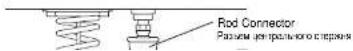
Loosen the center rod fixing bolts to extend the center rod, and insert the center rod into the fitting of the rod connector. Align the groove in the center rod with the tip of the fixing bolt, and then securely tighten the fixing bolt.
● Для модели YY-520
10 Stand up the vibes, and attach the resonators. (Refer to YV-4110/3910/3710 assembly step4 on page 18.)
11 Mount the driver and the controller, and connect them using the supplied 8P DIN cable. (Refer to YV-4110/3910/3710 assembly steps 6) through 8 on pages 20 and 21.)
12 Attach the round belt (fan belt) ^* . Slip the round belt (tan belt) over the tan side pulley first, and then pull it over the flange of the driver pulley.
\* Note For Service Personnel
If the belt cannot be mounted because the distance between the pulleys is too wide, or the belt slips due to a too narrow pulley distance, loosen the two driver positioning screws (see illustration below) to adjust the pulley distance (bell tension). Tighton the screws securely after adjustment.
Fan Side
Сторона лопастей


Driver Positioning Screws
13 Adjust the pedal stroke. (Refer to YV-4110/3910/3710 assembly step 10-1 on page 23.)
14 After assembly, confirm that each bolt and screw is tightened securely.
15 Height adjustment should always be performed by at least 2 persons.
To adjust the height of the tone bars, first remove the round belt (fan belt), driver, controller and tone bars*, and loosen the center rod fixing bolts. (* To remove the tone bars, disengage the springs on the low sound side, and then unhook the string from the post.)
Support both frame ends by hand (do not touch the metal parts shown in the illustration), and loosen the slide leg fixing bolts.
For height adjustment, make sure to support the instrument by the wooden frame. Do not touch the metal parts.
Lift the frame ends to the desired height and then securely tighten each slide leg fixing bolt, aligning it with the corresponding notch of the slide leg. Bolt and notch are aligned when the next higher notch is flush with the upper leg flange. (Refer to step 8 on page 29.)
When a slide leg fixing bolt is tightened in between two notches, there is a danger of the
●Range:c-4, 4 Octaves ●Bars: Aluminum Alloy/Glossy Gold Finish, graduating from 1-1/8" to 2-1/5" wide, 1/2" thick ●Pitch:A = 442 Hz ●Drive Unit:YVM-300 (Pause-Memory Controller), 25-145 rpm ●Power Supply:YAMAHA AC Adapter PA-130 (D.C. 12V, 1A + - North America), PA-D015 (D.C. 15V, 1A + - Europe), or other adapter recommended by YAMAHA ●Power Consumption:2.9 W (PA-130), 3.6 W (PA-D015) ●Dimensions (Length x Width):185 x 83 cm (72-7/8" x 32-5/8") ●Height Adjustment:86-94 cm (33-7/8" - 37") ●Weight:64 kg (141.1 lbs) ●Oversized Castors:4" high
■YV-3910
●Range: C-13, 3-12 Octaves ●Bare: Aluminum Alloy/Glossy Gold Finish, graduating from 1-1/8" to 2-1/5" wide, 1/2" thick ●Pitch:A -442 Hz ●Drive Unit: YVM-300 (Pause-Memory Controller), 25-145 rpm ●Power Supply: YAMAHA AC Adapter PA-130 (D.C. 12V, 1A +○- North America), PA-D015 (D.C. 15V, 1A +○- Europe), or other adapter recommended by YAMAHA ●Power Consumption: 2.9 W (PA-130), 3.6 W (PA-D015) ●Dimensions (Length x Width): 164 x 83 cm (64-58" x 32-58") ●Height Adjustment: 86-94 cm (33-78" - 37") ●Weight: 61 kg (134.5 lbs) ●Oversized Castors: 4" high
■ YV-3710
●Range:1-43, 3 Octaves ●Bars:Aluminum Alloy/Glossy Gold Finish, graduating from 1-1/2" to 2-1/4" wide, 1/2" thick ●Pitch:A = 442 Hz ●Drive Unit:YVM-300 (Pause-Memory Controller), 25-145 rpm ●Power Supply:YAMAHA AC Adapter PA-130 (D.C. 12V, 1A + - North America), PA-D015 (D.C. 15V, 1A + - Europe), or other adapter recommended by YAMAHA ●Power Consumption:2.9 W (PA-130), 3.6 W (PA-D015) ●Dimensions (Length x Width):143 x 82 cm (56-1/4" x 32-1/4") ●Height Adjustment:86-94 cm (33-7/8" - 37") ●Weight:60 kg (132.3 lbs) ●Oversized Castors:4" high
■ YV-2700 / YV-2700G
Range:1-3, 3 Octaves Bars:Aluminum Alloy, graduating from 1-1/2" to 2-1/4" wide, 1/2" thick, YV-2700: Silver Satin Finish, YV-2700G: Glossy Gold Finish Pitch:A = 442 Hz Drive Unit:YVM-200 (Pause Controller), 25-145 rpm Power Supply:YAMAHA AC Adapter PA-130 (D.C. 12V, 1A1+ North America), PA-D015 (D.C. 15V, 1A1+ Europe), or Operational Control by YAMAHA. Power Consumption:2.7 W (PA-130), 3.6 W (PA-D015) Dimensions (Length x Width):143 x 82 cm (56-14" x 32-1/4") Height Adjustment:81-89 cm (31-7/8" 35") Weight:57 kg (125.6 lbs) Oversized Castors:4" highs
■ YV-520
●Range:f-13, 3 Octaves ●Bars:Aluminum Alloy ●Pitch:A = 442 Hz ●Drive Unit:YVM-100 (Pause Controller), 25-145 rpm ●Power Supply:YAMAHA AC Adapter PA-130 (D.C. 12V, 1A.1Ω, North America) PA D015 (D.C. 15V, 1A.1Ω
- SPECIAL MESSAGE SECTION
- Information for Users on Collection and Disposal of Old Equipment and used Batteries
- In order to prevent fire, electric shock, and injury, make sure that all precautions described below are obeyed.
- About the icons
- Warning
- Disregard of the warnings denoted with this mark and misuse of the product can lead to death or serious injury.
- Safety Precautions
- Caution
- PRECAUTIONS
- ● Do Not Use Outdoors
- - Keep This Manual for Future Reference
- ● Handling
- ● Перекладины
- ● Опора педали
- ● Демпфер
- Connect the large and the small leg using the reinforcement stay and pedal stay.
- Attach the sustain damper.
- Attach the resonators.
- Set the tone bars.
- Attach the driver.
- Connect the driver with the controller.
- Note For Service Personnel
- 10-1 Pedal Stroke Adjustment
- РЕГУЛИРОВКИ
- 10-2 Wire Clip Adjustment
- 10-3 Damper Spring Adjustment
- ■ Power Supply
- ■ Источник питания
- ■ PAUSE MEMORY FUNCTION SETTING (YV-4110/3910/3710 only)
- YV-2700/2700G/520
- Assembly / Сборка
- For YV-520
- ● Для модели YY-520
- \* Note For Service Personnel
- Fan Side
- Сторона лопастей
- Driver Positioning Screws
- ■YV-3910
- ■ YV-3710
- ■ YV-2700 / YV-2700G
- ■ YV-520
Brand : YAMAHA
Model : YV-3910M
Category : Musical instrument