
R4N86NNU - Tracking ORION - Free user manual and instructions
Find the device manual for free R4N86NNU ORION in PDF.


Pick your language and provide your email: we'll send you a specifically translated version.
| Product Type | Professional LCD Monitor |
| Resolution | 3840 x 2160 (UHD) |
| Brightness | 500 cd/m² |
| Contrast Ratio | 1000:1 (43") / 1100:1 (55", 65") |
| Viewing Angle (H/V) | 178° / 178° |
| Display Color | 1.07 billion |
| Response Time | 8 ms |
| Aspect Ratio | 16:9 |
| Input Interfaces | VGA, DVI, HDMI (3), DP In/Out, USB (FW update) |
| Output Interface | Audio Line Out, RS-232 Out |
| Control Interface | RS-232 In/Out, Keypad, Remote Control (IR) |
| Video Wall Support | Up to 81 displays (9x9) with position setting |
| Bezel Width (H/V) | 18.8 mm / 21.4 mm (for 55", 65") |
| Panel Technology | LCD (LED backlight) |
| Video System | NTSC/PAL |
| Deinterlacing | Yes |
| Auto Pixel Shift | Yes |
| User Control | OSD menu via keypad or remote |
| Cleaning | Use soft cloth; unplug before cleaning; avoid liquid cleaners |
| Safety | Do not remove back cover; avoid water and direct sunlight; ensure ventilation |
Frequently Asked Questions - R4N86NNU ORION
How do I set up a video wall with multiple R4N86NNU monitors?
To configure a video wall, use the On-Screen Display (OSD) menu. Navigate to the 'Video Wall' section and enable it. Set the 'Position' according to your monitor layout (1 to 81) and adjust 'H Ratio' and 'V Ratio' for horizontal and vertical counts. Use the joint brackets supplied to align monitors. For detailed commands, refer to the R4N Commander protocol in the manual.
How should I clean the monitor safely?
Before cleaning, unplug the monitor from the power outlet. Use a soft, dry cloth to wipe the screen. Do not use liquid cleaners, chemical liquids, or abrasive materials, as they may cause fading or damage. Avoid pressing hard on the LCD panel.
What input sources are available on the R4N86NNU?
The monitor supports VGA, DVI, three HDMI inputs, and DisplayPort (DP) input. It also has a DP output for daisy-chaining. A USB port is provided for firmware updates. Use the remote or keypad to select the desired source.
How do I adjust the OSD settings?
Press the 'MENU/EXIT' button on the keypad or remote to display the OSD menu. Use the directional buttons to navigate and adjust settings like Brightness, Contrast, Color Temperature, and more. Press 'ENTER' to confirm and 'EXIT' to close.
What should I do if the screen does not display any image?
First, ensure the power cable is properly connected and the monitor is turned on. Then, verify that the correct input source is selected (e.g., HDMI, DVI). If using a PC, press the 'AUTO' key to auto-adjust the VGA signal. If the problem persists, contact a service center.
Can I control the monitor remotely?
Yes, the monitor comes with a remote controller that allows you to power on/off, mute, select inputs, adjust color temperature, and activate PIP mode. For advanced control, use the RS-232 interface with a PC running the R4N Commander protocol.
Is wall mounting supported?
Yes, the monitor can be mounted using the joint brackets supplied. Ensure the wall is stable and the mounting area allows proper ventilation. For video wall installations, contact a professional installer.
What is the warranty coverage?
The product carries a limited warranty from the ship date against defects in materials and workmanship. Improper installation or damage from mounts, adapters, or personal injury is not covered. Contact your dealer for detailed terms.
How do I update the firmware via USB?
Download the latest firmware from the manufacturer's website. Save it to a USB drive and insert it into the USB port labeled 'FW Update'. Use the OSD menu to initiate the update. Do not unplug the monitor during the process.
How can I control the monitor via RS-232?
Connect a PC to the RS-232 input using a D-Sub 9-pin cable. Use the R4N Commander protocol (VWCP) with commands like 'PWR' for power, 'MIN' for source change, and 'RML' for remote lock. The protocol uses 13-byte packets with STX (0x0f) and ETX (0x0d). Refer to the command list in the manual for details.
User questions about R4N86NNU ORION
0 question about this device. Answer the ones you know or ask your own.
Ask a new question about this device
No questions yet. Be the first to ask one.
Download the instructions for your Tracking in PDF format for free! Find your manual R4N86NNU - ORION and take your electronic device back in hand. On this page are published all the documents necessary for the use of your device. R4N86NNU by ORION.
USER MANUAL R4N86NNU ORION
| 1 SAFETY INSTRUCTION 3 | |
| 2 FCC RF INTERFERENCE STATEMENT 7 | |
| 3 INSTALLATION 8 | |
| 4 OSD MENU SETTING 13 | |
| 5 SPECIFICATION 21 | |
| 6 R4N COMMANDER (Video Wall Control Protocol) 24 | |
| 7 TROUBLESHOOTING 35 | |
| 8 LIMITED WARRANTY 35 |
[USER MANUAL]
1. SAFETY INSTRUCTION
\- Follow this safety instruction to use the monitor properly and prevent the damage. * This safety instruction has "Warning" & "Caution" as below  Warning - If the user does not follow this instruction, it may cause the serious damage to the user.  Caution - If the user does not follow this instruction, it may cause the slight damage to the user or cause some damages to the monitor. \- Keep this user's guide book for later use. Warning
Never remove the back cover and touch the inside of the monitor. If you need a service, please contact the service center.  Keep away the monitor from the direct sunlight and a heating appliance. [USER MANUAL]
Warning
Do not install this monitor on the outside and near water. It may cause damage to the product, electric shock and fire.  For cleaning do not use liquid cleaners. Never touch the power plug with wet-hands.  When lightning and thundering, unplug the monitor from the wall outlet and never touch it.  Unplug this product from the wall outlet, when it does not operate for a long time.  When smoking and noising from the monitor, unplug the product from the wall outlet and contact a service center.[USER MANUAL]
Cautions
Install this monitor some distance from the wall and do not install unless proper ventilation is provided.  Place this product on a stable place. If not, it may fall, causing serious damages to the monitor and people.  The openings must not be blocked by curtain, rug or other similar surface.  When carrying this monitor, be careful not to damage the panel and drop it. It may cause some trouble.  Before carrying the monitor, turn it off and Take the power plug out from the wall[USER MANUAL]
Cautions
Install this monitor about 50cm far from the eyes and an angle of 0\~15 degrees below eyes. Too close installation may cause having weak sight.  Do not press the LCD panel with hands or the sharpened material hardly.  For cleaning, unplug the monitor from the wall outlet. Do net use the liquid cloth. Use the soft cloth.  Do not use the chemical liquid for cleaning. It may cause fading and breakage.  WARNING: TO REDUCE THE RISK OF ELECTRIC SHOCK, DO NOT EXPOSE THIS EQUIPMENT TO BAIN OR WATER[ USER MANUAL ]
2. FCC RF INTERFERENCE STATEMENT
NOTE
This equipment has been tested and found to comply with the limits for a Class A digital device, pursuant to Part 15 of the FCC Rules. These limits are designed to provide reasonable protection against harmful interference in a residential installation. This equipment generates, uses and can radiate radio frequency energy and, if not installed and used in accordance with the instructions, may cause harmful interference to radio communications. However, there is no guarantee that interference will not occur in a particular installation. If this equipment does cause harmful interference to radio or television reception which can be determined by turning the equipment off and on, the user is encouraged to try to correct the interference by one or more of the following measures. - Reorient or relocate the receiving antenna. - Increase the separation between the equipment and receiver. - Connect the equipment into an outlet on a circuit different from that to which the receiver is connected. - Consult the dealer or an experienced radio, TV technician for help. - Only shielded interface cable should be used. Finally, any changes or modifications to the equipment by the user not expressly approved by the grantee or manufacturer could void the users authority to operate such equipment. [USER MANUAL]3. INSTALLATION
3.1 UNPACKING
Remove the package cover and place the product on a flat and secure surface or in the installation location. This equipment should be unpacked and handled with care. If an item appears to have been damaged in shipment, notify the shipper immediately. Check whether all the following device and accessories are included with the main system. If any items are missing, notify your Sales or Customer Service Representative.3.2 PARTS
 LCD Monitor & Keypad  Joint Bracket(2EA) & BHMS M4x8 BK(8EA)  Power Cable    LTD Cable, DB Cable, HDMI Cable [USER MANUAL]3.3 KEYPAD
1) KEYPAD CONTROLLER  if you want to replace with a longer cable Please purchase separately *Depending on the product model type, there may be variations in appearance.| OSD KEY FUNCTION | |
| EXIT MENU | On/Off the OSD menu or exit the source selection menu |
| ▼SOURCE | Move the cursor the choose on the OSD menu |
| Select the source on the INPUT menu | |
| ▲ | Move up the cursor to choose on the OSD menu |
3.4 CONNECTION
 ① ② ③ ④ ⑤ ⑥ ⑦ ⑧ ⑨ ⑩ ⑪ ⑫ ⑬ ⑭ ⑮| 1 | VGA VGA signal input | |
| 2 | DVI | DVI signal input |
| 3 | HDMI1 | HDMI signal Input |
| 4 | HDMI2 | HDMI signal Input |
| 5 | HDMI3 | HDMI signal Input |
| 6 | DP IN | DP signal input |
| 7 | USB | FW Update Input |
| 8 | DP OUT | DP signal output |
| 9 | Audio | Audio Line Output |
[USER MANUAL]
3.5 CONFIGURE THE VIDEO WALL
1. You can combine two or more monitors, and configure the VIDEO WALL. 2. If you want to configure VIDEO WALL, please contact your dealer or a professional installer. 3. JOINT BRACKET helps to easily adjust the VIDEO WALL (Supplied with monitor) 4. Using a JOINT BRACKET can help to prevent distortion or sagging due to weight, But may not be available in an installation environment where there is no space behind the product. * Assemble the JOINT BRACKET using four M4 screws.  CABLE CONNECTION *Chla connection order, it may be different  [USER MANUAL]3.6 REMOTE CONTROLLER
| POWER Power On or Off | |
| MUTE Turn on or off | the speaker |
| VIDEO1/CVBS1 Not functional | |
| VIDEO2/CVBS2 Not functional | |
| S-VIDEO Not functional | |
| VGA Select VGA signal | |
| AUTO Auto adjustment of VGA source | |
| COLOR TEMP Select color temperature of screen | |
| DVI Select DVI signal | |
| HDMI | Select HDMI signal(HDMI1→HDMI2→HDMI3) |
| DP Select DP signal | |
| HDMI2/CAMERA Not functional | |
| SDI Select SDI signal(Not functional) | |
| S.SET Not functional | |
| SCAN MODE Select scan mode of screen | |
| PIP | Activate PIP mode |
[USER MANUAL]
4. OSD MENU
4.1 Main OSD Menu
Press a menu button "MENU/EXIT" on a KEYPAD or a remote controller to display this menu on the screen.  [USER MANUAL]4.3 Image
| ITEM FUNCTION | Default Value | Available Mode |
| Brightness Adjust a bright value between 0 ~ 100 80 |
4.4 Color
| ITEM FUNCTION | Default Value | Available Mode | |
| Color | Select the color Temperature | Normal All | |
4.5 Multi-Window
 Please note that while using Multi-Window function, HDMI1 and HDMI3 can't be selected simultaneously. (In this case, an error may occur)| ITEM FUNCTION | Default Value | Available Mode |
| PIP Type Select a PIP mode Off, PIP, PBP, 3 Window or 4 Window Off All |
4.6 Video Wall
| ITEM FUNCTION | Default Value | Available Mode | |
| Set ID Adjust the Set ID value between 1 ~ 99 99 | All | ||
| Video Wall Enable Set Off or On to enable a video wall mode ON | |||
| Position | Set the sequence of installed monitors on the video wall situation(1 ~ 81) | 1 | |
| H Ratio | Set the total number of horizontally installed monitors on the video wall situation(1 ~ 01) | 1 | |
| 1 | 2 | 3 | 4 |
| 5 | 6 | 7 | 8 |
| 9 | 10 | 11 | 12 |
| 13 | 14 | 15 | 16 |
4.7 VGA
 [USER MANUAL] 4.8 OSD | ITEM FUNCTION | Default Value | Available Mode | |
| Horizontal | Adjust a horizontal position of the main menu between | 95 | |
4.9 SYSTEM
| ITEM FUNCTION | Default Value | Available Mode | |
| Language | Select a language type of OSD Menu. | English | |
5. SPECIFICATION
5.1 General Specifications| Model Name R4N43NNU R4N55NNU R4N65NNU | ||||
| Bezel Width BEZEL to BEZEL 15.8 / 20.4(H/V) 18.8 / 21.4(H/V) 18.8 / 21.4(H/V) | ||||
| Display | Screen Size (inch) 42.51" 54.64" 64.53" | |||
| Resolution 3840 x 2160 3840 x 2160 3840 x 2160 | ||||
| Pixel Pitch (mm) 0.2451 x 0.2451 0.315 x 0.315 0.372 x 0.372 | ||||
| Brightness 500 cd/m2 500 cd/m2 | 500 cd/m2 | |||
| Contrast Ratio | 1000:1 | 1100:1 | 1100:1 | |
| Aspect Ratio | 16:9 | 16:9 | 16:9 | |
| Viewing Angle (H/V) | 178/178 | 178/178 | 178/178 | |
| Display Color | 1.07 billion | 1.07 billion | 1.07 billion | |
| Response Time | 8 ms | 8 ms | 8 ms | |
| Video System | NTSC/PAL | NTSC/PAL | NTSC/PAL | |
| Interface | *DP In / Out | 1/1 | 1/1 | 1/1 |
| *HDMI In | 3 | 3 | 3 | |
| DVI In / VGA In | 1 | 1 | 1 | |
| RS-232 In/Out | 1/1 | 1/1 | 1/1 | |
| USB(FW UPDATE) | 1 | 1 | 1 | |
| Audio Out | 1 | 1 | 1 | |
| Remote Control | Y | Y | Y | |
| Special Features | RS-232 Control | Monitor OSD & Multi Vision | Monitor OSD & Multi Vision | Monitor OSD & Multi Vision |
| Deinterlacing | Y | Y | Y | |
| Auto Pixel Shift Y | Y | Y | ||
| One Stretch Image by Edge Set | Y | Y | Y | |
| MODE Resolution | Vertical Frequency(Hz) | Input Standards | ||
| EDTV 480p 720x480 59.94 | D-SUB/HDMI/DP | EIA-861B | ||
| EDTV 576p 720x576 50.00 | ||||
| HDTV720p 1280x720 50/60 | ||||
| HDTV1080i 1920x1080 50/60 HDMI/DP | ||||
| HDTV1080p 1920x1080 24/25/30/50/60 D-SUB/HDMI/DP | ||||
| UHDTV2160p 3840x2160 24/25/30 HDMI/DP | ||||
| UHDTV2160p 3840x2160 50/60 | DP | |||
| VGA | 640x480 | 60/72/75 | D-SUB/HDMI/DP | VESA |
| SVGA | 800x600 | 56/60//72/75 | D-SUB/HDMI/DP | VESA |
| XGA | 1024x768 | 60/75 | D-SUB/HDMI/DP | VESA |
| WXGA | 1280x720 | 60 | D-SUB/HDMI/DP | VESA |
| WXGA | 1280x800 59.9 | D-SUB/HDMI/DP VESA | ||
| WXGA | 1366x768 59.8 | D-SUB/HDMI/DP VESA | ||
| SXGA | 1280x1024 | 60/75 | D-SUB/HDMI/DP | VESA |
| FHD | 1920x1080 | 60 | D-SUB/HDMI/DP | VESA |
| UXGA | 1600x1200 | 60 | D-SUB/HDMI/DP | VESA |
5.3 Video Wall RS232 Assignment / Specification
| - D-SUB 9 pin- Input: Female, bottom position | Pin No. Name | 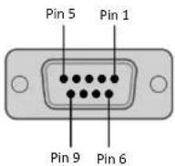 Input Input | |
| 1 n/c | |||
| 2 | Tx | ||
| 3 | Rx | ||
| 4 | NC | ||
| 5 GND | |||
| 6 n/c | |||
| 7 n/c | |||
| 8 n/c | |||
| 9 5V(option) | |||
| - D-SUB 9 pin- Output: Male, top position | Pin No. Name | 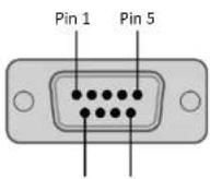 | |
| 1 n/c | |||
| 2 | Rx | ||
| 3 | Tx | ||
| 4 | NC | ||
| 5 GND | |||
| 6 n/c | |||
[ USER MANUAL ]
6. R4N COMMANDER (Video Wall Communication Protocol)
This document defines all the command and messages exchanged between the Master (a PC or the other controller) and the Slave (the displays). It also describes the ways to send or read the commands or the messages.6.1 Protocol definition
VWCP stands for "Video Wall Communication Protocol". The protocol is specifically designed to allow data communication in half duplex multi-point environments, but it can also be used for full duplex point-to-point RS-232C communication.6.2 Communication characteristics
A half-duplex communication is implemented starting from the concept of a master-slave structure, where the display is supposed to be the slave. The first action is always taken by the master, which can be either a PC or any controlling device (acting as server) interfaced to the monitor. After sending a command or a request in the appropriate format the master receives from the slave an acknowledgement, which tells the transmitter whether the command is not valid (or not executable, anyway) or it is accepted. In case of a request, the requested information is sent back and it becomes the acknowledgement by itself.6.3 How to connect an external equipment(PC ↔ Monitor)
Female Pin number Male Pin number[ USER MANUAL ]
6.5 Transmission Formats
This is the format that the computer will send to the display to execute commands. The format for this command transmission is as follows: \- Data Length: 13 byte Ex)| STX ID | 1 ID2 ID3 | CM1 CM | 2 CM3 R/W DA1 | DA2 DA3 | IND ETX | |||||||
| 0x0f | 0 | 0 | 1 | P | W | R | W | O | F | F | 0 | 0x0d |
| Hex | ASCII (capital letter) | Hex | ||||||||||
[ USER MANUAL ]
6.6 Command List (Write)(PC ↔ Monitor)
Power On/Off (PWR)| STX ID | 1 ID2 ID3 | CM1 CM | 2 CM3 R/W DA1 | DA2 DA3 | ND ETX | ||||||
| 0x0f P | W R W O | 0x0d | |||||||||
| Hex | ASCII (capital letter) | Hex | |||||||||
| STX ID | 1 ID2 ID3 | CM1 CM | 2 CM3 R | W DA1 | DA2 DA3 | ND ETX | ||||||
| 0x0f | R | M | L | W | 0 | 0x0d | ||||||
| Hex | ASCII (capital letter) | Hex | ||||||||||
[USER MANUAL]
Line Shift On/Off (LIN)| STX ID | 1 ID2 ID3 | CM1 CM | 2 CM3 R/W DA1 | DA2 DA3 | IND ETX | ||||||
| 0x0f L | IN W | 0 | 0x0d | ||||||||
| Hex | ASCII (capital letter) | Hex | |||||||||
| STX ID | 1 ID2 ID3 | CM1 CM | 2 CM3 R | W DA1 | DA2 DA3 | ND ETX | ||||||
| 0x0f | M | U | T | W | 0 | 0x0d | ||||||
| Hex | ASCII (capital letter) | Hex | ||||||||||
| STX ID1 ID2 ID3 | CM1 CM | 2 CM3 R/W DA1 | DA2 DA3 | ND ETX |
[USER MANUAL]
Virtual Remote Control (RMT)| STX ID | 1 ID2 ID3 | CM1 CM | 2 CM3 R/W DA1 | DA2 DA3 | IND ETX | ||||||
| 0x0f R | M T W 0 | 0x0d | |||||||||
| Hex | ASCII (capital letter) | Hex | |||||||||
| STX ID | 1 | ID2 ID3 | CM1 CM | 2 | CM3 R | W DA1 | DA2 DA3 | ND ETX | ||||||
| 0x0f | H | S | C | W | 0 | 0x0d | ||||||||
| Hex | ASCII (capital letter) | Hex | ||||||||||||
[USER MANUAL]
Vertical Set Count (VSC)| STX ID | 1 ID2 ID3 | CM1 CM | 2 CM3 R/W DA1 | DA2 DA3 | ND ETX | ||||||
| 0x0f V | S C W | 0 | 0x0d | ||||||||
| Hex | ASCII (capital letter) | Hex | |||||||||
| STX ID1 ID2 ID3 | CM1 CM | 2 CM3 R/W DA1 | DA2 DA3 | ND ETX | |||||||
| 0x0f | H | E | G | W | 0 | 0x0d | |||||
| Hex | ASCII (capital letter) | Hex | |||||||||
Vertical Edge Adjust (VEG)
[USER MANUAL]
Display Sequence (SDS)| STX ID | 1 ID2 ID3 | CM1 CM | 2 CM3 R/W DA1 | DA2 DA3 | IND ETX | ||||||
| 0x0f S | D S W 0 | 0x0d | |||||||||
| Hex | ASCII (capital letter) | Hex | |||||||||
| STX ID1 ID2 ID3 | CM1 CM | 2 CM3 R/W DA1 | DA2 DA3 | ND ETX | ||||||
| 0x0f CT | CW 0 | 0x0d | ||||||||
| Hex | ASCII (capital letter) | Hex | ||||||||
[USER MANUAL]
Contrast Adjust (FCC)| STX ID | 1 | ID2 ID3 | CM1 CM | 2 | CM3 R/W DA1 | DA2 DA3 | IND ETX | ||||||
| 0x0f | F | C | C | W | 0 | 0x0d | |||||||
| Hex | ASCII (capital letter) | Hex | |||||||||||
| STX ID1 ID2 ID3 | CM1 CM | 2 CM3 R/W DA1 | DA2 DA3 | ND ETX | |||||||
| 0x0f | F | G | R | W | 0 | 0x0d | |||||
| Hex | ASCII (capital letter) | Hex | |||||||||
| STX | ID1 | ID2 | ID3 | CM1 | CM2 | CM3 | R/W | DA1 | DA2 | DA3 | IND | ETX |
[USER MANUAL]
Blue Gain Adjust (FGB)| STX ID | 1 ID2 ID3 | CM1 CM | 2 CM3 R/W DA1 | DA2 DA3 | ND ETX | ||||||
| 0x0f F | G B W | 0 | 0x0d | ||||||||
| Hex | ASCII (capital letter) | Hex | |||||||||
| STX ID1 ID2 ID3 | CM1 CM | 2 CM3 R | W DA1 | DA2 DA3 | ND ETX | |||||||
| 0x0f | F | O | R | W | 0 | 0x0d | ||||||
| Hex | ASCII (capital letter) | Hex | ||||||||||
| STX | ID1 | ID2 | ID3 | CM1 | CM2 | CM3 | R/W | DA1 | DA2 | DA3 | IND | ETX |
| 0x0f | F | O | G | W | 0 | 0x0d | ||||||
| Hex | ASCII (capital letter) | Hex | ||||||||||
6.7 Command List (Read)
Edge Item Read Command (PC → Monitor)| STX | Set ID | ID | Sequence | H Count | V Count | H Gap | V Gap | ETX | ||||
| 0x0f E | 0 0 0 0 x0d | |||||||||||
| Hex | ||||||||||||
| STX | Set ID | ID | Bright | Contra | Color Temp | Red Gain | Green Gain | Blue Gain | Red Offset | Green Offset | Blue Offset | ETX |
| 0xOf C | 0x0d | |||||||||||
| Hex | ||||||||||||
[USER MANUAL]
Model Info < New > Read Only (PC → Monitor)| STX ID | 1 ID2 ID3 | CM1 CM | 2 CM3 R/W DA1 | DA2 DA3 | IND ETX | ||||||
| 0x0f M | D L R O | 0x0d | |||||||||
| Hex | ASCII (capital letter) | Hex | |||||||||
| STX | Set ID | ID | MDL1 | MDL2 | MDL3 | PNL1 | PNL2 | VER1 | VER2 | VER3 | VER4 | ETX |
| 0x0f | '1' | 0 | 0x0d | |||||||||
| Hex | ||||||||||||
→ RNK OLD VERSION: No Response
Ex) RNK New Version| STX | Set ID | ID | MDL1 | MDL2 | MDL3 | PNL1 | PNL2 | VER1 | VER2 | VER3 | VER4 | ETX |
| 0x0f | 'Y' | 'R' | 'N' | 'K' | 0x00 | 0x00 | 0x00 | 0x00 | 0x00 | 0x01 | 0x0d | |
| Hex | ||||||||||||
[ USER MANUAL ]
7. TROUBLESHOOTING
When the following troubles are occurred, follow the trouble shooting. Before contacting a service center.| Troubleshooting Troubleshooting | Tip |
| The screen doesn't show up | 1. Make sure if the power supply is connected property |
| 2. Turn on the power. | |
| 3. Select the input signal right for the connected port. | |
| The screen is too light or to dark Control the BRIGHTNESS | |
| The screen size is not fit for the PC signal | Press the AUTO key among keys in the front. (It's used only in the PC signal) |
| The screen color shows strange in the PC signal | In the FUNCTION menu of OSD menu, perform the AUTOADJUST |
8. LIMITED WARRANTY
All products carry a limited warranty from ship date against defects in materials and workmanship. We are not liable for improper installation that results in damage on mounts, adapters, display equipment or personal injury.


Table of contents
Click a title to access it
- [USER MANUAL]
- SAFETY INSTRUCTION
- WARNING
- CAUTIONS
- [ USER MANUAL ]
- FCC RF INTERFERENCE STATEMENT
- NOTE
- INSTALLATION
- 3.1 UNPACKING
- 3.2 PARTS
- 3.3 KEYPAD
- 3.4 CONNECTION
- 3.5 CONFIGURE THE VIDEO WALL
- 3.6 REMOTE CONTROLLER
- OSD MENU
- 4.1 MAIN OSD MENU
- INFORMATION OF WINDOWS
- TITLE OF MAIN MENU
- ICON OF MAIN MENU
- SUB MENU
- VERSION OF FW
- IMAGE
- 4.3 IMAGE
- 4.4 COLOR
- 4.5 MULTI-WINDOW
- 4.6 VIDEO WALL
- 4.7 VGA
- 4.9 SYSTEM
- SPECIFICATION
- 5.3 VIDEO WALL RS232 ASSIGNMENT / SPECIFICATION
- R4N COMMANDER (VIDEO WALL COMMUNICATION PROTOCOL)
- 6.1 PROTOCOL DEFINITION
- 6.2 COMMUNICATION CHARACTERISTICS
- 6.3 HOW TO CONNECT AN EXTERNAL EQUIPMENT(PC ↔ MONITOR)
- 6.5 TRANSMISSION FORMATS
- 6.6 COMMAND LIST (WRITE)(PC ↔ MONITOR)
- VERTICAL EDGE ADJUST (VEG)
- 6.7 COMMAND LIST (READ)
- → RNK OLD VERSION: NO RESPONSE
- TROUBLESHOOTING
- LIMITED WARRANTY
Manual assistant
Powered by Anthropic
Waiting for your message
Product information
Brand : ORION
Model : R4N86NNU
Category : Tracking