RSEP1S25P - Water heater Rinnai - Free user manual and instructions
Find the device manual for free RSEP1S25P Rinnai in PDF.

User questions about RSEP1S25P Rinnai
0 question about this device. Answer the ones you know or ask your own.
Ask a new question about this device
Download the instructions for your Water heater in PDF format for free! Find your manual RSEP1S25P - Rinnai and take your electronic device back in hand. On this page are published all the documents necessary for the use of your device. RSEP1S25P by Rinnai.
USER MANUAL RSEP1S25P Rinnai
natural_image
Technical line drawing of a rectangular industrial ventilation duct with cooling fins and ventilation grilles (no text or symbols)Super High-Efficiency (SE+) Series Infrared Gas Heater
Installation and Operation Manual
Rinnai®
All models approved:
■ ANSI Z83.26-2014 / CSA 2.37-2014
■ Gas-Fired Infrared Patio Heater for Outdoor Commercial / Residential Application
■ ANSI Z83.19a-2011 / CSA 2.35a-2011
■ Gas-Fired High Intensity Infrared Heater for Commercial /Industrial Non-Residential Application for either indoor or outdoor installation
NOTICE:
Rinnai reserves the right to make changes to equipment and specifications without obligation or notification. This publication, or parts thereof, may not be reproduced in any form, without prior written consent from Rinnai. Unauthorized use or distribution of this publication is strictly prohibited.
All models constructed with Marine Grade Stainless Steel Cabinet

Improper installation, adjustment, alteration, service or maintenance can cause property damage, injury or death.
Read the installation and operating and maintenance instructions thoroughly before installing or servicing this equipment.
SAFETY ALERT:
This heater must be installed and serviced only by a trained gas service technician. Failure to comply could result in personal injury, death, fire and/or property damage.
Do not store or use gasoline or other flammable vapors and liquids in the vicinity of this or any other gas fired appliance.
Indoor Applications: The heater cannot be used indoors in a residence.
IF YOU SMELL GAS:
■ Extinguish any open flame
■ Do not attempt to light this or any other appliance
- Don’t touch any electrical switch, or telephone
- Immediately leave the area and call your gas supplier from a neighbor's phone
■ Follow any and all instruction from your gas supplier
■ If your gas supplier is not available, call the fire department
FIELD CONVERTIBILITY:
This appliance is field convertible to LP gas (except RSEP2S50N: NG only).
Only use kit available from Rinnai.
Follow kit instructions and all local and national codes.
INSTALLER: PRESENT THIS MANUAL TO THE END USER.
Keep this manual in a secure place.
Record for future reference:
Model #:
Serial #:
(located on heater rating label)
GAS-FIRED

Gas-fired Infrared Patio Heater for Outdoor Commercial / Residential Application, and Gas-Fired Luminous (High Intensity) Infrared Heater for Commercial / Industrial Non-Residential Application for either indoor or outdoor installation
TABLE OF CONTENTS
TOPIC
PAGE NUMBER

IMPORTANT INFORMATION - READ FIRST
IMPORTANT WARNINGS....4
HEATER EXPANSION 5
GAS CONNECTION....5
VENTING 5,13
MOUNTING & CLEARANCE DISTANCES: OUTDOOR PATIO INSTALLATION ....6 INDOOR INSTALLATION ....9
- APPLICATION 11
OUTDOOR / PATIO....11
INDOOR INSTALLATION 11
-
AIRCRAFT HANGARS....12
-
GARAGES & PARKING STRUCTURES...... 12
-
OTHER THAN SPACE HEATING....12
-
PRE-INSTALLATION SURVEY 12
-
INSTALLATION REQUIREMENTS....13
6.1 MOUNTING CLEARANCES ..... 13
6.2 HEATER MOUNTING....13
- GAS SUPPLY PIPING....14
7.1 GAS PRESSURE 14
TOPIC
PAGE NUMBER
-
ELECTRICAL - BASIC REQUIREMENTS ..... 14
-
INSTALLATION PROCEDURES.... 15
-
LIGHTING INSTRUCTIONS.... 16
10.1 SHUT DOWN INSTRUCTIONS ..... 16
-
HEATER FINISH & APPEARANCE 16
-
SERVICING GUIDE...... 17
-
VENTILATION FOR INDOOR APP'S .... 19
-
DIMENSIONS & CONFIGURATION....20
-
MOUNTING KIT OPTIONS....21
-
ELECTRICAL REQUIREMENTS.... 24
16.1 CONTROL OPTIONS....24
-
SEQUENCE OF OPERATION-FENWAL 35-60 DSI....25
-
SPARK IGNITION CIRCUIT 26
-
WIRING DIAGRAM....27
-
TROUBLESHOOTING GUIDE ...... 30
-
COMMISSIONING REPORT 32
-
HIGH ALTITUDE INSTALLATION 34
-
REPLACEMENT PARTS LIST.... .35 - 36

IMPORTANT
Installer: Present this manual to the end user. Acquaint the end user with Important Information: Cover & pages 4 to 10.

END USER: In particular you must be aware of 'Clearances to Combustible' requirements and the limitations of stacking or placing material near the heaters.
Inform your safety personnel and staff of this information.

WARNING

Improper installation, adjustment, alteration, service or maintenance can cause property damage, injury or death. Read and understand this installation and operation manual thoroughly prior to assembly, installation, operation or service to this appliance.
This heater must be installed and serviced only by a trained gas service technician.
Do not store or use gasoline or other flammable vapours and liquids in the vicinity of this or any other gas fired appliance.

Failure to comply to these warnings could result in personal injury, death, fire and/or property damage.
This appliance may have sharp edges and corners. Wear protective clothing such as gloves and protective eye wear when servicing this or any other appliance.

California Proposition 65:
WARNING: This product can expose you to chemicals including carbon monoxide, which is known to the State of California to cause birth defects or other reproductive harm. For more information, go to www.P65Warnings.ca.gov

WARNING
DO NOT INSTALL THIS APPLIANCE IN A RECESS, ALCOVE, OR ENCLOSURE.
While minimum clearances to combustibles are stipulated to ensure safe installation, adequate free space must be provided to allow the products of combustion to escape from the heater to atmosphere when installed outdoors, or through mechanical exhaust withdrawal when installed indoors. Also refer to “Outdoor” and “Indoor” definitions and requirements on page 11. Do not allow the products of combustion to accumulate in any space or enclosure.

WARNING
Due to the effects of radiant heat upon certain materials it is not recommended to store or place items that could be damaged or
distorted, directly under this heater....i.e. combustible patio furniture etc.
• Clothing or other flammable materials should not be hung from, or placed near to the heater
- Children and Adults should be alerted to the hazards of high surface temperatures and should be careful to avoid burns or clothing ignition
• Young children should be carefully supervised when in the area of a heater

WARNING
This heater is not for installation in a Class 1 or Class 2 explosive environment, nor for any residential application. If installa-
tion of this equipment is in question, consult with local authorities having jurisdiction (Fire Marshal, labor department, insurance underwriter, or others).
Revisions to codes and/or standards, may require revision to equipment and installation procedures. In case of discrepancy, the latest codes, standards, and installation manual will take priority over prior releases.
IMPORTANT: DO NOT INSTALL THIS HEATER INDOORS IN A STRUCTURE WITH NO INSULATION IN THE ROOF—CONDENSATION WILL OCCUR.

WARNING
Heater Expansion

It is a normal condition that during heat-up and cool-down a radiant heater will expand and contract. Allowances for heater expansion must be made in the gas connection and heater suspension. Improper installation, alteration, or adjustment can result in property damage, injury or death.

WARNING
Gas Connection

Improper installation, connection, or adjustment can result in property damage, toxic gases, asphyxiation, injury or death. Use an approved stainless steel flexible gas connector (field supplied) to connect to the gas supply to the heater in accordance with all local, state, provincial, and national codes (ANSI Z223.1/NFPA 54 in USA) and as indicated in this manual.

WARNING
Venting


Inadequate venting of a heater may result in asphyxiation, carbon monoxide poisoning, injury or death. When used indoors, this heater is indirectly vented from the space. Venting must be in accordance with all local, state, provincial, and national codes (ANSI Z223.1/
NFPA 54 in USA) and as indicated in this manual. Refer to Page 19

WARNING
Start-up 'Smoke' & Discoloration Condition
During start-up, the heating of material coatings used in the production process of the heater may create a small amount of smoke during the initial period of operation. This condition is normal and temporary.
Ensure that there is sufficient ventilation to adequately clear any 'smoke' from the space.
Notify site management and safety personnel to ensure that alarm systems are not unduly activated.
WARNING
Heater Discoloration / Staining
Stainless Steel & Painted Finishes: Surface discoloration or staining will occur on any heater body due to heat. Surface finish discoloration due to heat is a normal occurrence. Surface discoloration does not affect the operation or performance of the heater nor Rinnai's component warranties. (Refer to Section 11: Heater Finish & Appearance, page 16)
Some discoloration can result from the deposit of ambient air-borne particulate or gases from within the space that have passed through combustion to create 'smoke'. The combustion of fuel gas in a clean environment will not cause smoke discoloration deposits.
WHEN INSTALLED AS AN OUTDOOR PATIO HEATER
• See pages 9 - 10 for Indoor installation, and Ventilation Requirements page 19
- Also refer to "Outdoor" and "Indoor" definitions and requirements on page 11

WARNING
Certain materials or items, when stored under the heater, will be subjected to radiant heat and could be seriously damaged.
Location of flammable or explosive objects, liquids or vapors close to the heater may cause fire or explosion and result in property damage, injury or death. Do not use, store or locate flammable or explosive objects, liquids or vapors in proximity of the heater.

The clearance to combustible material represents the minimum distance that must be maintained between the outer heater surface and a nearby surface. The stated clearance to combustibles represents a surface temperature of 117F^ ( 65C^ ) above ambient temperature when installed outdoors.
It is the installer's responsibility to ensure that building materials with a low heat tolerance which may degrade at lower temperatures are protected to prevent degradation. Examples of low heat tolerance materials include vinyl siding, fabrics, some plastics, filmy materials, etc.
It is beyond the scope of these instructions to consider all conditions that may be encountered. Consult local authorities such as the Fire Marshall, insurance carrier, or safety authorities if you are uncertain as to the safety or applicability of the proposed installation.
Refer to Table 1 & Figure 1 Next Page for the minimum mounting and clearances to combustibles for Outdoor Patio application.

WARNING
DO NOT INSTALL THIS APPLIANCE IN A RECESS, ALCOVE, OR ENCLOSURE.
Adequate free space must be provided to allow the products of combustion to escape from the heater to atmosphere when installed outdoors, or to mechanical exhaust withdrawal when installed indoors. Do not allow the products of combustion to accumulate in any space or enclosure.
Note: Do not store or place anything directly under heater
Ensure mounting height in any location is sufficient to prevent patrons from coming in contact with heater, and clearance to combustibles is maintained.
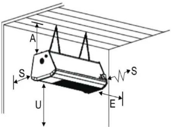
Figure 1: OUTDOOR - MINIMUM CLEARANCES (Indoor Clearances Page 10)
NOTE: ANGLE MOUNT IS MAXIMUM 30° TO AVOID DAMAGE
HORIZONTAL INSTALLATION

text_image
A S U E SINSTALLATION AT 30°

text_image
T B U E FTable 1: OUTDOOR - MINIMUM CLEARANCES TO COMBUSTIBLES
| Application | MODEL NO | Horizontal | 30° Angle | Under | Ends | |||
| A | S | T | B | F | U | E | ||
| OUTDOOR | RSEP1S25X - NG/LPG | 5.5" | 7" | 9.5" | 1" | 9.5" | 48" | 3" |
| OUTDOOR | RSEP1S35X - NG/LPG | 7.5" | 9" | 9.5" | 1.5" | 21" | 48" | 5" |
| OUTDOOR | RSEP2S50N - NG Only | 12" | 28" | 16" | 10" | 36" | 60" | 21" |
See Table 2 Next Page for "Suggested Mounting Height for Comfort"
Note: Do not mount less than 8 ft [2438 mm] above floor. Do not store or place anything directly under heater
Ensure mounting height in any location is sufficient to prevent patrons from coming in contact with heater, and clearance to combustibles is maintained.
The clearance to combustible material represents the minimum distance that must be maintained between the outer heater surface and a nearby surface. In an OUTDOOR application the stated clearance to combustibles represents a surface temperature of 90^ ( 50^ ) above ambient temperature.
It is the installer's responsibility to ensure that building materials with a low heat tolerance which may degrade at lower temperatures are protected to prevent degradation. Examples of low heat tolerance materials include awnings, vinyl siding, fabrics, some plastics, filmy materials, etc.
Table 2: SUGGESTED MOUNTING DISTANCES FOR COMFORT
| MOUNTING PARAMETERS *** | MODEL RSEP1S25X 23,000 Btuh | MODEL RSEP1S35X 35,000 Btuh | MODEL RSEP2S50N 50,000/35,000 Btuh | |||
| A - Mounting angle | Horizontal | Max. 30^0 | Horizontal | Max. 30^0 | Horizontal | Max. 30^0 |
| H - Suggested height above deck/floor | 8' to 10' | 8' to 10' | 8' 6" to 11' | 8' 6" to 11' | 9' to 12' | 9' to 12' |
| S - Side distance to patio edge | 3' 6" | 3' 6" | 4' 0" | 4' 0" | 5' 0" | 5' 0" |
| Y - Side distance between heaters | 6' 0" | 6' 0" | 8' 0" | 8' 0" | 9' 0" | 9' 0" |
| W - Distance effective coverage | 6' 0" | 7' 0" | 7' 0" | 8' 0" | 8' 6" | 9' 6" |
| Z - Front distance between heaters | 12' 0" | 14' 0" | 14' 0" | 16' 0" | 17' 0" | 19' 0" |
Figure 2: MOUNTING PARAMETER DISTANCES
![Rinnai RSEP1S25P - Note: Do not mount less than 8 ft [2438 mm] above floor. Do not store or place anything directly under heater - 1](/content/2026/06/1215049/images/3f451448926bee0bd5d2951752121b192e32975003163a852dbdf3f097c1c72a.jpg)
text_image
S Y C Y Z A (Maximum 30°) V W H W H*** Note: Mounting angles and distances are suggested to ensure comfort, and are subject to site and design conditions.
If in doubt, please contact your Rinnai distributor.
Ensure mounting height in any location is sufficient to prevent patio patrons from coming in contact with the heater.
WHEN INSTALLED INDOORS FOR COMFORT OR SPACE HEAT
- Also refer to "Outdoor" definition and requirements on page 11
• And refer to Indoor Ventilation Requirements page 19
WARNING
Clearance to Combustibles
Location of flammable or explosive objects, liquids or vapors close to the heater may cause fire or explosion and result in property damage, injury or death. Do not use, store or locate flammable or explosive objects, liquids or vapors in proximity of the heater.

The clearance to combustible material represents the minimum distance that must be maintained between the outer heater surface and a nearby surface. The stated clearance to combustibles represents a surface temperature of 90^ ( 50^ ) above room temperature.
It is the installer's responsibility to ensure that building materials with a low heat tolerance which may degrade at lower temperatures are protected to prevent degradation. Examples of low heat tolerance materials include vinyl siding, fabrics, some plastics, filmy materials, etc.
In locations used for the storage of combustible materials, signs must be posted to specify the maximum permissible stacking height to maintain the required clearances from the heater to the combustibles. Such signs must either be posted adjacent to the heater thermostats or in the absence of such thermostats in a conspicuous location.
In addition to stored or stationary material, consideration must also be given to moveable objects such as cranes, vehicles, and overhead doors, and structural objects such as electrical and gas lines, electrical fixtures, and sprinkler heads.
Heaters must be located an appropriate distance from sprinkler heads. This distance may be greater than the certified clearance to combustibles. Check the temperature rating of the sprinkler heads and locate heaters at a safe distance - in some instances the sprinkler heads may need to be replaced by higher temperature heads.
It is beyond the scope of these instructions to consider all conditions that may be encountered. Consult local authorities such as the Fire Marshall, insurance carrier, or safety authorities if you are uncertain as to the safety or applicability of the proposed installation.
Refer to Figure 3 and Table 3 NEXT PAGE for the mounting requirements and certified clearances to combustibles for indoor installation. Also refer to ventilation requirements for indoor installations on page 19.

WARNING
DO NOT INSTALL THIS APPLIANCE IN A RECESS, ALCOVE, OR ENCLOSURE.
Adequate free space must be provided to allow the products
of combustion to escape from the heater to atmosphere when installed outdoors, or to mechanical exhaust withdrawal when installed indoors. Also refer to "Outdoor" and "Indoor" definitions and requirements on page 11.
Do not allow the products of combustion to accumulate in any space or enclosure.
Figure 3: INDOOR - MOUNTING CLEARANCES (Outdoor Clearances Page 7)
NOTE: ANGLE MOUNT IS MAXIMUM 30° TO AVOID DAMAGE
HORIZONTAL INSTALLATION
text_image
A S U E SINSTALLATION AT 30°
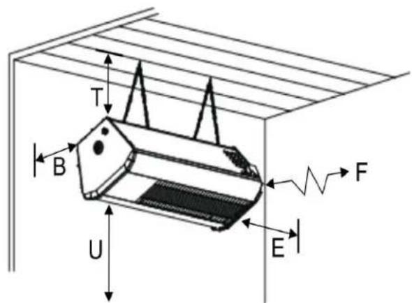
text_image
T B U E FTable 3: INDOOR - MINIMUM CLEARANCES TO COMBUSTIBLES
The clearance to combustible material represents the minimum distance that must be maintained between the outer heater surface and a nearby surface. The stated clearance to combustibles represents a surface temperature of 90^ ( 50^ ) above indoor room temperature.
It is the installer's responsibility to ensure that building materials with a low heat tolerance which may degrade at lower temperatures are protected to prevent degradation. Examples of low heat tolerance materials include awnings, vinyl siding, fabrics, some plastics, filmy materials, etc.
Table 4: INDOOR - SUGGESTED MOUNTING HEIGHT FOR COMFORT
| MOUNTING PARAMETERS *** | MODEL RSEP1S25X 23,000 Btuh | MODEL RSEP1S35X 35,000 Btuh | ||
| Mounting angle | Horizontal | MAX. 30^0 | Horizontal | MAX. 30^0 |
| Suggested height above deck/floor | 9' 0" | 9' 0" | 10' 0" | 10' 0" |
- APPLICATION: All models are approved to ANSI Z83.26-2014 / CSA 2.37-2014 for heating of outdoor commercial / industrial / residential patios and areas, and are also approved to ANSI Z83.19a-2011 / CSA 2.35a-2011 for heating indoor and outdoor commercial / industrial / non-residential spaces.
It is beyond the scope of these instructions to consider all conditions that may be encountered. Installation in the USA must conform to all local and national code requirements including the current National Fuel Gas code ANSI Z223.1, and the National Electrical Code ANSI/NFPA No 70 (latest edition). In case of discrepancy due to revisions to standards and codes, the latest standards, codes, and installation manual are in effect and take priority.
DO NOT INSTALL THIS APPLIANCE IN A RECESS, ALCOVE, OR ENCLOSURE.
Adequate free space must be provided to allow the products of combustion to escape from the heater to atmosphere when installed outdoors, or to mechanical exhaust withdrawal when installed indoors. Also refer to “Outdoor” and “Indoor” definitions and requirements below.
Do not allow the products of combustion to accumulate in any space or enclosure.
OUTDOOR / PATIO Installation:
This heater is certified for use outdoors. Rinnai warrants that the heater will operate as designed for patio use in wind conditions up to 10 MPH. Higher wind speeds exceeding 10 MPH can adversely affect heater performance and human comfort conditions on the patio.
What is "Outdoor"?
An appliance approved for “outdoor use” may be installed with shelter no more inclusive than:
- With walls on all sides, but with no overhead cover, (overhead permanently open)
- Or Within a partial enclosure which includes an overhead cover and no more than two side walls. These side walls may be parallel, as in a breezeway, or at right angle to each other. The open sides must be permanently open
- Or Within a partial enclosure which includes an overhead cover and three side walls, as long as 30 percent or more of the horizontal periphery of the enclosure is permanently open.
If an “outdoor” condition is not met, this heater is approved for “indoor use”. Ventilation requirements of local codes apply. See “Indoor Installation” below.
INDOOR Installation:
This heater is certified for space or spot heating of commercial / industrial non-residential indoor spaces in accordance with ANSI Z83.19 / CSA 2.35.

WARNING
Inadequate venting of a heater may result in asphyxiation, carbon monoxide poisoning, injury or death. Heating system vent-
ing must be in accordance with all local, state, provincial, and national codes (ANSI Z223.1/NFPA 54 in USA).
INDOOR INSTALLATION IN A STRUCTURE THAT HAS NO INSULATION IN THE ROOF CAN RESULT IN THE FORMATION OF CONDENSATION ON COLD SURFACES.
2. INSTALLATION IN COMMERCIAL AIRCRAFT HANGARS
Luminous (high intensity) radiant tube heaters are suitable for use in aircraft hangars when installed in accordance with the latest edition of the Standard for Aircraft Hangars, ANSI/NFPA No 409 in the USA.
A. A minimum clearance of 10 ft (3 m) above either the highest fuel storage compartment or the highest engine enclosure of the highest aircraft which may occupy the hangar. The clearance to the bottom of the heater shall be measured from the upper surface of either the fuel storage compartment or the engine enclosure, whichever is higher from the floor.
B. A minimum clearance of 8 ft (2.4 m) must be maintained from the bottom of the heater to the floor in other sections of the aircraft hangar, such as offices and shops, which communicate with areas for servicing or storage. Refer to Table 1 for proper mounting clearances to combustibles.
C. Heaters must be located so as to be protected from damage by aircraft and other objects, such as cranes and movable scaffolding.
D. Heaters must be located so as to be accessible for servicing and adjustment.
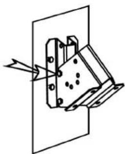
3. INSTALLATION IN COMMERCIAL GARAGES AND PARKING STRUCTURES
Luminous (high intensity) radiant heaters are suitable for use in commercial garages when installed in accordance with the latest edition of the Standard for Parking Structures, ANSI/NFPA 88A, or the Standard for Repair Garages, ANSI/NFPA No. 88B.
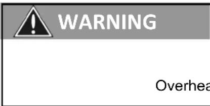
text_image
WARNING OverheaAn overhead heater shall be located to maintain the minimum distance to combustibles, as shown on the heater rating plate, from the heater to any vehicles parked below the heater.
Overhead heaters shall be installed at least 8 ft (2.4 m) above the floor.
4. INSTALLATIONS OTHER THAN SPACE HEATING
Use for process or other applications that are not space heating will void the C.S.A. certification and product warranty. Process application requires field inspection and/or certification by local authorities having jurisdiction. Process application design should be provided by local experienced process design experts.
5. PRE INSTALLATION SURVEY
It is recommended that a full heating design including heat loss calculation be conducted on the structure or area to be heated. Heater sizing and placement must consider available mounting height, sources of greatest heat loss, and obstructions on the site. The certified clearances to combustibles with respect to stored material, moveable objects (cranes, vehicles, lifts,
overhead doors, etc), structural components, and sprinkler system heads. Consideration must also be given to ventilation fan placement (outdoor heaters do not require ventilation). Carefully survey the area to be heated, and for best results place heaters in the coldest area(s) and at sufficient spacing to provide uniform radiant heat coverage.
Installation must conform with all local, state, provincial and national code requirements including the current latest edition ANSI Z223.1 (NFPA 54) in the U.S.A. The latest edition Electrical Code ANSI/NFPA N0 70 in the U.S.A. must also be observed.
The heating system must have gas piping of the correct diameter, length, and arrangement to provide for and satisfy the total system input. A layout drawing is necessary to calculate properly sized gas supply piping.
6. INSTALLATION REQUIREMENTS
6.1 MOUNTING CLEARANCES
The SE+ Series Heaters must be mounted with minimum clearances to combustible materials. Refer to the introductory section “Clearance to Combustibles” pages 6 to 10 and to Table 1 and Figure 1 page 7 (Outdoor) or Table 3 and Figure 3 page 10 (Indoor).
THIS HEATER HAS HOT SURFACES: Minimum mounting height is to be no less than 87" above the floor / deck. Do not locate heater where patrons can come into contact with heater. Do not store or place items directly underneath heater. Maintain clearance to combustibles.
The heater must be located with respect to building construction and equipment so as to provide sufficient clearance and accessibility for servicing of burner and ignition control and cleaning. Provide adequate clearance around air openings into the combustion chamber.
6.2 HEATER MOUNTING
This heater must be rigidly mounted to prevent movement from wind force.
Refer to Table 2 and Figure 2. The SE+ Series Heaters are approved for both horizontal and 30° angle mounting on the short axis. Rinnai specifies a MAXIMUM 30° mounting angle - if the short axis is rotated to an angle exceeding 30°, damage to the heater or unsafe operation can result, and will void warranty.
IMPORTANT: For either horizontal or up to 30^ angle mounting, the long axis of the heater must be level. Use only non-combustible mounting hardware. Figures 6 & 7 on Page 21 illustrate typical suspension hardware that may be used, and provided by Rinnai as an optional component.
7. GAS SUPPLY PIPING
- All piping must be installed according to applicable local and national codes
- A listed flexible connector (field supplied) must be installed between the heater and gas supply piping. For outdoor installation the connector must be in compliance with ANSI Z21.75 / CSA 6.27. An optional 3/8" x 24" black finish flexible gas connector (part number 903000012 - approved Indoor/Outdoor) is available from Rinnai.
- A drip-pocket must be provided in the gas piping at the inlet connection
- Provide a 1/8" NPT plugged tapping, accessible for test gage connection, immediately upstream of the gas supply connection to the heater.
- On propane-fired units, a main line filter is recommended (field supplied)
- Piping joint compounds must be resistant to the action of liquefied petroleum gases
- All piping joints must be tested for leaks with a soap and water solution.
CAUTION: DO NOT INSTALL ANY GAS PIPING IN HEAT ZONES
7.1 GAS PRESSURE
The maximum supply pressure must be limited to 14"w.c. (0.5 psi). If the line pressure is above 14"w.c., then a separate pressure reducing regulator must be installed. The minimum pressure at the inlet to the heater regulator must be equal to or greater than 6.0"w.c. for natural gas and 11.0"w.c. for propane gas.
Proper manifold pressure must be established during commissioning, and will be maintained when the main burner is operating under the following supply pressure:
| Table 5 | LINE PRESSURE "w.c. | MANIFOLD PRESSURE "w.c. AT GAS VALVE TEST PORT | ||
| MODELS GAS TYPE | MINIMUM MAXIMUM | |||
| RSEP1S25X, RSEP1S35X | NATURAL GAS | 6.0 | 14.0 | 5.0 |
| PROPANE GAS | 11.0 | 14.0 | 10.0 | |
| RSEP2S50N (2-Stage) | NATURAL GAS (ONLY) | 6.0 | 14.0 | 5.0 High; 3.0 Low |
Natural Gas: Orifice sized for 1000 BTU/CU.FT.
Propane Gas: Orifice sized for 2500 BTU/CU.FT.
8. BASIC ELECTRICAL REQUIREMENTS - see also Section 16 page 25
All electrical installations must meet local codes and the latest edition ANSI/NFPA N0 70 in the U.S.A.
TRANSFORMER SPECIFICATIONS (field supplied)
Single heater requires 24 Volt, 60 Hz electrical transformer sized at 40 VA.
Multiple heaters in a zone are powered by a single transformer (field supplied). The proper transformer is 24 Volt AC, 60 Hz, sized at 40VA for the first heater plus 20VA for each additional heater in the zone - round up the calculated value to the next higher available sized transformer. For example, four heaters in a zone require a transformer of : 1 x 40VA + 3 x 20 VA = 100 VA . It is not recommended to install more than 12 heaters per zone.
PROPER WIRING POLARITY MUST BE MAINTAINED, particularly when grouping the heaters in a zone. Total wiring distances of up to 200' must use minimum 16 gauge electrical wire, and wiring distances of over 200' must use minimum 14 gauge electrical wire. The heater must be electrically grounded in accordance with local and national electrical codes. Malfunction of the heating system will result if the voltage varies by more than ±10%.
The heater can be controlled by a line voltage thermostat, a 24 volt thermostat or “off-on” switch. Total load of all heaters must be considered in determining the required contact rating of the controlling thermostat or switch.
9. INSTALLATION PROCEDURES
a) Properly install gas line to all local codes
b) Mount heaters using non-combustible mounting hardware
c) Observe all minimum clearances as indicated: OUTDOOR in Table 1 and Figure 1, page 7; INDOOR in Table 3 and Figure 3, page 10.
d) Suggested mounting distances for comfort in Table 2 and Figure 2 are guidelines based on experience. Site conditions can allow for some deviation from these distances.
WARNING: This heater must be rigidly mounted to prevent movement from wind force.
When using Mounting Brackets, ensure that anchoring to the structure is of sufficient strength, integrity and workmanship, to support the weight of the heater and any other loads such as snow and wind force.
e) Connect heater to the main gas line. An approved 1/2" flexible connector (field supplied - available as an option from Rinnai) must be used to absorb heater and gas line expansion and any vibration - check local code requirements.
f) Check gas line for leaks by using soap test or gas meter test. Ensure gas pressure meets the requirements outlined in Section 7.1 (above).
WARNING: When testing the main gas line pressure up to 0.5 psig, ensure that the isolation valve and combination gas valve are "OFF", otherwise damage to the combination gas valve will result. When testing main gas line in excess of 0.5 psig the appliance and shut off valve must be disconnected or isolated from the gas supply piping system during any such pressure testing. Gas supply to the heater must be regulated to be maximum 0.5 psig (14"w.c.) and minimum values listed in Table 3 above in Section 7.1
g) All wiring must comply to local and national codes. The heater requires 24Vac power supply. The heater system zone requires a field supplied 120/24Vac transformer rated at 40VA for the first heater plus 20VA for each additional heater in the zone. Ensure proper electrical rating in the system by checking voltage at ignition module terminals. To avoid system malfunction, the voltage range must be within 10% of required 24Vac (21.6 Volts to 26.4 Volts), and correct polarity must be maintained throughout the system.
h) Test-fire the heating system by following the lighting instructions listed below and on the heater label.
10. LIGHTING INSTRUCTIONS
- Ensure the correct voltage is supplied, gas supply lines have been properly purged, and gas valve is switched to the ON position.
- Turn on power to heater, set thermostat (if applicable) to above ambient temperature, the heater will light.
- If heater does not light: Turn off power to heater, turn gas valve to OFF position.
- Wait for five minutes and repeat steps above. If heater does not light after three attempts, call a qualified service technician.
10.1 SHUT DOWN INSTRUCTIONS
a) For temporary shutdown, turn off the electrical supply circuit.
b) For complete shutdown, turn off the electrical circuit and turn gas control knob to the "OFF" position.
11. HEATER FINISH AND APPEARANCE
All models are constructed with a marine grade stainless steel enclosure cabinet, with optional finish of stainless steel, or high temperature black coating.
Stainless Steel Enclosure Heater: ALL stainless steel heaters will discolor or stain to some extent due to the impact of heat. This is a normal occurrence and does not effect heater performance or the warranty of components.
High Temperature Coating Finish Heater: Exterior heater surfaces, including any stainless steel components, are coated with a black high emissive coating that helps preserve the aesthetic appearance of the heater and improves the radiant heat output.
Handle the heater with care during installation and service to avoid scratching or damaging the finish.
With extended use, the finish coat will discolor and deteriorate to some extent due to the impact of heat, the deposit of ambient air born particles, and environmental factors.
These are normal occurrences caused by heat, products of combustion, and the environment, and in no way affect the operation / performance of the heater or Rinnai's warranty.
OCCASIONAL PAINT FINISH MAINTENANCE:
Wear protective gloves, eyewear, and breathing mask. Ensure that power to the heater is disconnected prior to maintenance and the application of any finish coating. Use a fine steel wool to remove blemishes or unsightly deposit, and smooth the outer surface. The heater finish coat can be touched up using a high temperature coating such as Thurmalox Stove Paint - Flat Black-1200°F (650°C) or similar high temperature stove paint that is compatible with the original finish. No other coating or non-high-temperature paint finish may be applied to the heater – use of an incompatible finish coating will create a hazardous condition such as fire or noxious fumes, damage the heater, and void the warranty.
Apply the touch up finish with the heater in its operating orientation (facing down). Ensure that overspray does not reach or effect the egg crate grilles and the burner tile surface - mask the heater grilles during any re-finishing. Remove the masking immediately after re-finish and prior to operation of the heater.
12. SERVICING GUIDE (Also refer to Troubleshooting Guide on page 29)
Servicing of heater is essential for continued efficient operation. Servicing should be carried out annually by a qualified gas service technician as follows:
- Clean the ceramic tiles with compressed air. Avoid directing air stream at gasket material between tile and heater body. The air pressure must be lower than 20 psig.
- Clean venturi tube with compressed air. The air pressure must be lower than 20 psig.
- Ensure gas orifice is clean and the heater cabinet is free of any debris
Indication of back firing:
- Loud ignition noise, followed by distinct hissing sound.
• Little or no visible burning on the ceramic tile surface. - Combustion is taking place inside the burner body.
WARNING: If heater backfires during operation, it must be turned off immediately.
Cause & remedy of back firing:
- Improper gas pressure entering the venturi tube: check pressure.
- Breakage of a ceramic tile and or gasketing: - replace damaged part.
- Faulty sealing of the ceramic tile to the burner body, caused by breakdown of gasket material: contact your local distributor or contractor.
HEATER SERVICING POSITION:
WHEN USING WALL MOUNT BRACKET 903000024 (see Figure 4 next page), the heater may need to be rotated 'up' so that access is provided to the service access door at the rear side of the heater that is against the wall.
- To allow rotation of the heater, slacken the upper bolt fastening the heater bracket to the wall mounting bracket.
- Remove the lower bolt securing the two brackets and rotate the heater up to the service position.
- Insert the bolt in the upper bracket hole to hold the heater for servicing, and apply locking nut to bolt for extra safety. Heater panel can now be accessed and serviced safely.
- NOTE: Do not start up the heater when in this upper service position as the gas valve is in a compromised position. Before starting the heater, ALWAYS restore the heater bracket back to its original plane and correct support position.
- To restore the heater to the operating position, lift and support the weight of the heater and remove nut and bolt from upper hole.
- Slowly rotate the heater back down to the correct operating position.
- Insert and fasten the bolt in the bottom hole, and secure with the nut.
- At completion of service, ensure that both bracket support bolts are tightened securely.
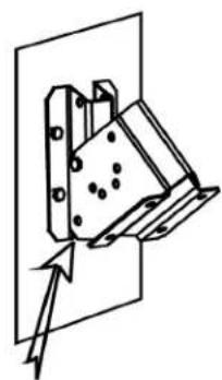
Figure 4: HEATER SERVICE POSITION WITH WALL MOUNT BRACKET
FOR SERVICING HEATER: (To simplify illustration the heater is not shown)
IT IS NOT NECESSARY TO REMOVE HEATER FROM SUPPORT BRACKET DRAWINGS SHOW JUST THE BRACKET FOR BETTER VIEW
ROTATE TO SERVICE POSTITION
①

natural_image
Pure mechanical assembly diagram without any text, numbers, or symbolsLOOSEN TOP BOLT TO ALLOW ROTATION
②
natural_image
Pure mechanical assembly diagram without any text, numbers, or symbolsREMOVE BOTTOM BOLT
③
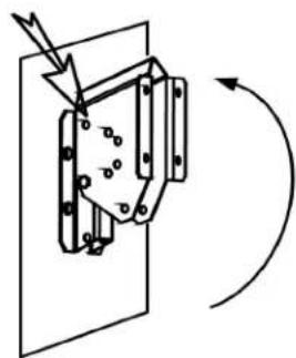
natural_image
Diagram of a mechanical device with rotating arrows indicating motion (no text or symbols)ROTATE TO SERVICE POSITION
④
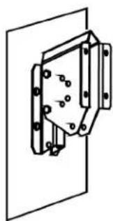
natural_image
Pure mechanical assembly diagram without any text, numbers, or symbolsALIGN TOP HOLES & INSERT BOLT
natural_image
Pure mechanical assembly diagram without any text, numbers, or symbolsSUPPORT HEATER & REMOVE TOP BOLT
②
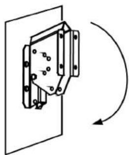
natural_image
Pure mechanical assembly diagram showing a bracket mounted on a plate with rotation arrow (no text or symbols)natural_image
Pure mechanical assembly diagram without any text, numbers, or symbolsALIGN BOTTOM HOLES & INSERT BOLT
④
natural_image
Pure mechanical diagram showing a bracket with arrows indicating direction, no text or symbols presentTIGHTEN BRACKET SUPPORT BOLTS
13. VENTILATION REQUIREMENTS FOR INDOOR APPLICATION

WARNING
Inadequate venting of a heater may result in asphyxiation, carbon monoxide poisoning, injury or death. Heating system venting must be in accordance with all local, state, provincial, and national codes (ANSI Z223.1/NFPA 54 in USA).
This heater is approved for unvented (indirect venting) application. Ensure that there is adequate ventilation to supply combustion air and to dilute the products of combustion in accordance with all local, state, provincial, and national codes. A balanced exhaust / inlet air system is required to ensure that a negative air condition is not created. See below for a summary of exhaust capacity requirements by the national codes in the U.S.A.
Air Supply: A “loose” building may not require any additional air supply if infiltration rates are sufficient to offset exhaust volume. However, for “tighter” buildings, or if air movement is stagnant in an area, air can typically be supplied via inlet(s) with an area of 1 sq. in. per 1,000 Btuh input (22 sq cm per kW). Locate air inlet(s) up at the level of the heaters to avoid cold drafts at work level, and effectively supply combustion and dilution air to the heaters and balance the system.
Heater Zoning: Exhausters are sized according to the input requirements of each controlled zone of heaters. Multiple smaller zones are usually more effective in both comfort and ventilation control than one large zone. Maximum zone size is limited by the total input that can be handled by the capacity of an exhauster, and by the proximity of the exhauster to heaters in the zone.
Exhauster Location & Proximity: Exhaust must be located as high as practicable in the structure above the level of the heater(s) to effectively dilute and remove the warm (rising) products of combustion. The exhauster should be as centrally located as practicable in the zone of heaters. Rinnai recommends a maximum 6:1 ratio of the horizontal distance between the exhauster and the furthest heater in a zone, to the height the heaters are mounted above the floor. For example, if heaters are mounted 20 ft above the floor, then the exhaust fan should be located no more than 120 ft from the furthest heater in the zone. Sufficient air supply must be provided.
Exhaustor Capacity:
USA: Natural or mechanical means shall be provided to supply and exhaust at least 4ft ^3 /min/1000Btuh (0.38m ^3 /min/kW) Natural Gas input of installed heaters [4.5ft ^3 /min/1000Btuh (0..43m ^3 /min/kW) Propane input]. Some local codes may require an interlock to a dedicated exhaust fan. Consult your local code and ANSI Z223.1 latest edition for all venting requirements and practices.
14. HEATER DIMENSIONS & CONFIGURATIONS
Table 5: CAPACITIES & CONFIGURATIONS
| MODEL Voltage | VAC | Current amps | Btu/hr input Total Weight (Ibs). | Length < A > |
| RSEP1S25X (NG and LP) | 23,000 | 32 | ||
| RSEP1S35X (NG and LP) | 23,000 | 32 | ||
| RSEP2S50N (NG) | 24 40 | VA* | 35,000 | 44 |
| 35,000 | 44 | |||
| 50,000/35,000 | 49 |
* For a multiple heater installation, the first heater is sized at 40VA and each consecutive heater is sized at 20VA. The sum total will be the required Transformer size. If total VA exceeds one transformer size select the next higher VA rated transformer.
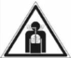
Figure 5: DIMENSIONS
text_image
Front View End View SCHWANK A 10" SCHWANK 13"15. MOUNTING KIT OPTIONS (NOTE: For unusual mounting application contact Rinnai.)
Optional mounting kits available:
| ITEM NO | PART NUMBER | DESCRIPTION |
| 1 903000009 CEILING MOUNT BRACKET | ||
| 2 903000022 WALL MOUNT BRACKET | ||
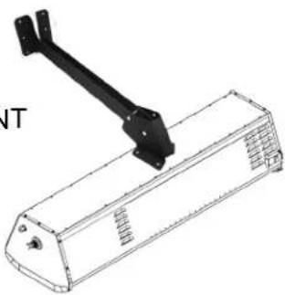
| 3 903000028 ARM MOUNT BRACKET | ||
| 4 903000026 POST BRACKET | ||
WARNING: This heater must be rigidly mounted to prevent movement from wind force.
Mounting Brackets: Ensure that anchoring to the structure is of sufficient strength, integrity and workmanship, to adequately support the weight of the heater and any other potential loads such as snow build up, and wind force.
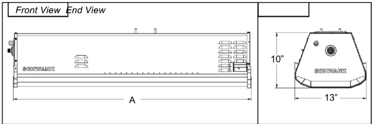
Figure 6: MOUNTING KIT OPTIONS
NOTE: MOUNT HEATER AT MAXIMUM 30° ANGLE TO AVOID DAMAGE This heater must be rigidly mounted to prevent movement from wind force.
ITEM 1: CEILING MOUNT
BRACKET KIT
903000009
Also see
next page
text_image
7" [178mm] 2" 2" 2" 2" [51mm] 3-3/8" [86mm] Ø 7/16" [11mm]ITEM 2: WALL MOUNT BRACKET
903000022

natural_image
Technical line drawing of two mechanical components with mounting holes and mounting holes (no text or symbols)ITEM 3: ARM MOUNTING KIT
903000028
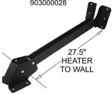
text_image
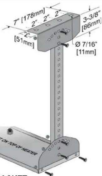
903000028 27.5" HEATER TO WALLITEM 4: POST MOUNT BRACKET
903000026


Figure 7: MOUNTING OPTIONS

text_image
ANGLE UP TO 45° ANGLE UP TO 30°WALL MOUNT
CEILING
MOUNT

text_image
60000 ANGLE UP TO 30° ONTARM MOUNT
natural_image
Technical line drawing of a mechanical component with a black lever and housing (no text or symbols)
natural_image
Technical line drawing of a mechanical component with no visible text or symbolsPOST MOUNT
903000009: Stainless Steel Ceiling Mount Kit for Patio Heaters
Component Quantities and Material Specifications each Kit:
2 x Ceiling Bracket - 12 ga. [0.102"] 316 S/S
2 x 24" [610 MM] Channel Leg - 12 ga. [0.102"] 316 S/S
2 x Heater Attachment Bracket - 12 ga. [0.102"] 316 S/S
12 x 14 " x 34 " Stainless Steel Bolts
12 x 14 " Stainless Steel KEP Nuts [lock washer attached]
Note: It is the installer's responsibility to ensure:
■ Adequate mounting strength and integrity to the structure using field supplied 3/8" lag screws or bolts
■ Maintain required clearances to combustibles from heater
■ Refer to manual: heater weights; required clearances
Assembly: (Fig 8)
The 24" [610 mm] Channel Leg can be cut to a shorter length
■ Ensure required clearances to combustibles from heater are maintained
Fasten the Ceiling Bracket and Heater Attachment Bracket to the Channel Leg using two supplied 14 " bolts at each connection as illustrated.
The arc of holes in the Ceiling Bracket allows angling of the Channel Leg from the bracket up to 45^ , and/or mounting the bracket to a sloped ceiling.
The arc of holes in the Heater Attachment Bracket allows angle mount of the heater.
■ NOTE: Maximum allowed heater angle is 30^
Fasten an assembled mounting bracket to each end of the Heater Support Bracket [supplied on heater] using two 14 " bolts supplied.
Note:
The Ceiling and Heater Attachment Brackets can be fitted directly to one another (Fig 9) without the Channel Leg, and yet achieve minimum clearance of 5-1/2" [140 mm].
Discard the Channel Legs.
Figure 9: CEILING MOUNT
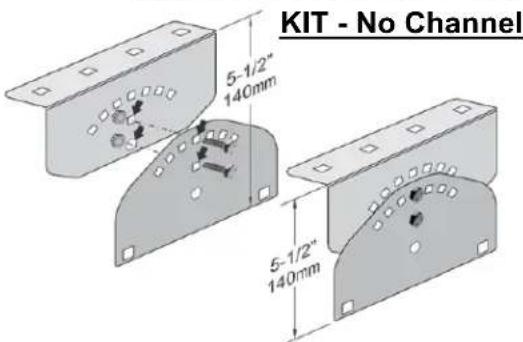
text_image
KIT - No Channel 5-1/2" 140mm 5-1/2" 140mmFigure 8: CEILING
MOUNT KIT
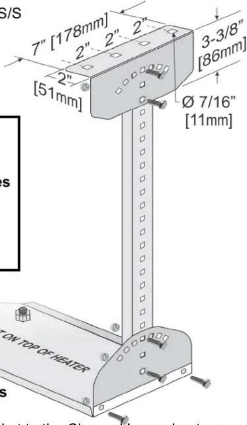
text_image
S/S 7" [178mm] 2" 2" 2" [51mm] 3-3/8" [86mm] Ø 7/16" [11mm] ON TOP OF HEATER s s Not to the Channeal PropertiesFigure 10: HEATER INSTALLATION: WALL MOUNT BRACKET
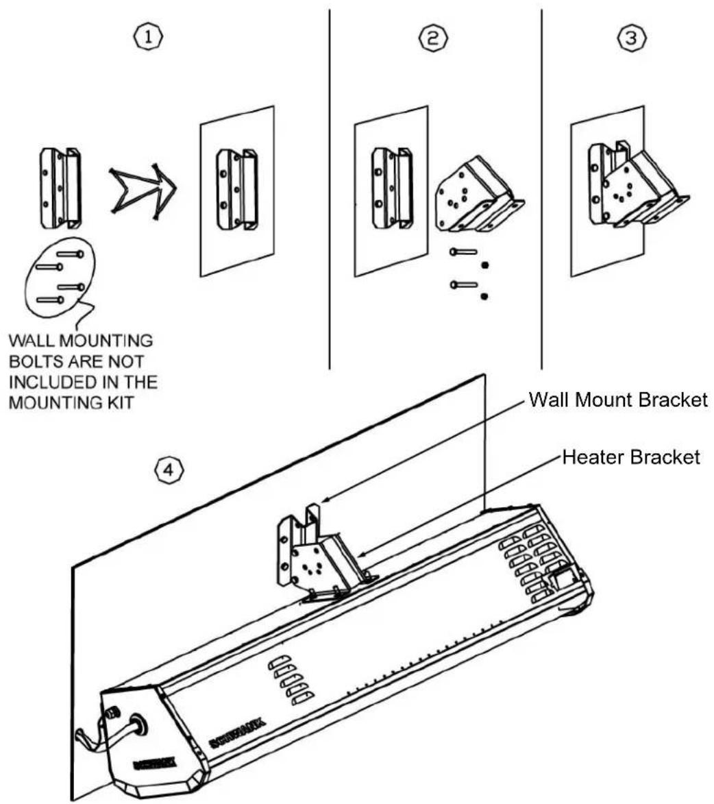
text_image
WALL MOUNTING BOLTS ARE NOT INCLUDED IN THE MOUNTING KIT ① ② ③ ④ Wall Mount Bracket Heater Bracket- Install the Wall Mount Bracket on the wall, using four bolts...(field supplied). See warning note (page 16) - ensure strength and integrity of mechanical fastening to structure
- Install the heater bracket on the heater using four nuts.
- Install the heater bracket to the wall mount bracket, and remove the lifting chains from the top of the heater.
NOTE: The heater should be installed with enough 'slack' on the wiring and a flexible gas connector to allow the rotation of the heater up to the service position.
(See service position information Figure 4 page 18).
16. ELECTRICAL REQUIREMENTS AND THERMOSTAT CONTROL
All electrical installations must meet local and the latest edition ANSI/NFPA N0 70 in the U.S.A.. Single heater requires 24 Volt, 60 Hz electrical transformer sized at 40VA. If multiple heaters are connected to a single transformer, the proper transformer is 24 Volt, 60 Hz, sized at 40VA for the first heater, and 20VA each for all subsequent additional heaters. For example, four heaters wired together (parallel), require a transformer of 100 VA. It is recommended to install at most 2 heaters per zone for best comfort control and economy of operation. PROPER WIRING POLARITY MUST BE MAINTAINED, particularly when grouping the heaters in a zone.
Total wiring distances of up to 200' must use minimum 16 gauge electrical wire, and wiring distances of over 200' must use minimum 14 gauge electrical wire. The heater must be electrically grounded in accordance with the local
electrical code. Malfunction of the heating system will result if the voltage varies by more than ±10% .
The heater can be controlled by a line moisture proof thermostat “off-on” switch, or Remote Control. Total load of all heaters must be considered in determining the required contact rating of the controlling thermostat or switch.
| RINNAI P/N | Transformer Description | Capacity |
| 903000034 | 120V/24V 100 VA | Up to 4 heaters |
| 903000035 | 120V/24V 150 VA | Up to 6 heaters |
| 903000036 | 120V/24V 200 VA | Up to 9 heaters |
| 903000037 | 120V/24V 250 VA | Up to 11 heaters |
| 903000038 | 120V/24V 350 VA | Up to 16 heaters |
16.1 CONTROL OPTIONS
Patio Heaters can be operated using Remote Control Option: (Except RSEP2S50N 2-stage)
• 903000030 Remote Receiver Kit (field installs in heater)
• 903000031 Remote Handset
• Refer to the manual accompanying the Remote Receiver Kit for installation.
Two-Stage Model RSEP2S50N requires one of the Illuminated Switch Gang 2-Stage Control options. These switches have (and must have) a special "Off", "On", "On" sequence that powers the heater and two-stage gas valve. Each switch is illuminated when in the "On" position for easy recognition of heater status.
| 24VAC SWITCH | CONTROL | PART # |
| Single Switch Gang | 1 Zone of 1 To 4 Heaters | 903000006 |
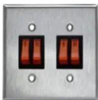
| Double Switch Gang | 2 Zones: 2 To 8 Heaters | 903000007 |
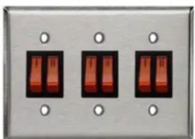
| Triple Switch Gang | 3 Zones: 3 To 12 Heaters | 903000008 |
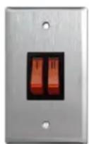
903000006
natural_image
Close-up of two identical electrical switch panels with three red buttons and mounting holes (no text or symbols visible)903000007
natural_image
Three identical electrical switch panels mounted on a metallic base with mounting holes (no text or symbols visible)903000008
17. SEQUENCE OF OPERATION FOR FENWAL 35-60 DSI CONTROL
Start up - Heat Mode:
On a call for heat the Fenwal 35-60 control will reset, perform a self-check routine, flash the diagnostic LED for up to four seconds. The gas valve and spark are energized commencing the trial for ignition period. When flame is detected during the trial for ignition, spark is shutoff immediately and the gas valve remains energized. The thermostat and main burner flame are constantly monitored to ensure the system continues to operate properly. When the thermostat is satisfied and the demand for heat ends, the gas valve is de-energized.
Flame Failure - Multi Trial Model:
Should the main burner fail to light, or the flame is not detected during the first trial for ignition period, the gas valve is de-energized and the control goes through an interpurge delay before another ignition attempt. The control will attempt two additional ignition trials before going into lockout and the valve relay is de-energized.
Recovery from lockout requires a manual reset by either resetting the thermostat or removing 24 volts for a period of 5 seconds. If the thermostat is still calling for heat after one hour the control will automatically reset and attempt to ignite the burner again.
Flame Failure - Re-Ignition:
If the established flame signal is lost while the burner is operating, the control will respond within 0.8 seconds. The HV spark will be energized for a trial ignition period in an attempt to relight the burner.
If the burner does not light the control will make two more attempts to relight the burner before de-energizing the gas valve. If the burner does not relight, the control will go into lockout as noted above in “Failure to light”. If flame is re-established, normal operation resumes. Multi-try models will allow three trials for ignition including interpurge delay between trials.
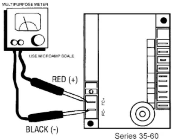
Flame current is the current which passes through the flame from the sensor to ground. The minimum flame current necessary to keep the Fenwal 35-60 system from lockout is 0.7 microamps ( A). To measure the flame current, connect analog DC microammeter to the FC-FC+ terminals.
Meter should read 0.7 A or higher. If the meter reads below "0" on scale, meter leads are reversed. Disconnect power and reconnect meter leads for proper polarity.
continued ...
text_image
MULTIPURPOSE METER USE MICROAMP SCALE RED (+) BLACK (-) FC- FC+ Series 35-60Cautions:
- The ceramic insulator of the igniter assembly should not be in or close to the flame.
- The electrode assembly should not be disassembled and care must be used in making minor gap adjustment. The spark electrode should have a gap spacing of 1/8"-3/16" (3.12±0.81 mm). If this spacing is not correct, the assembly must be carefully adjusted.
- Exceeding the temperature limits can cause nuisance lockouts and premature electrode failure.
The control must be secured in an area that will experience a minimum of vibration and remain below the maximum operating temperature of 160^ F.
18. SPARK IGNITION CIRCUIT
The step-up transformer in the ignition control provides spark ignition at 30,000 volts (open circuit). To check the spark ignition circuit, proceed as follows.
1 Shut off gas supply to the gas control
2 Disconnect the ignition cable at the ignition control stud terminal to isolate the circuit from the spark igniter or igniter/sensor
3 Prepare a short jumper lead, using heavily insulated wire such as ignition cable
CAUTION
In the next step, DO NOT allow fingers to touch either the stripped end of the jumper or the stud terminal. This is a very high voltage circuit and electrical shock can result.
1 Perform this test immediately upon energizing the system before the ignition control goes into safety lockout and interrupts the spark circuit. Touch one end of the jumper firmly to the ignition control GND terminal. (DO NOT remove the existing ground lead.) Slowly move the other end of the jumper wire toward the stud terminal on the ignition control to establish a spark.
2 Pull the wire away from the stud and note the length of gap at which spark discontinues.
3 A spark length of 1/8 in. (3mm) or more indicates satisfactory voltage output. If no arc can be established, or the maximum spark is less than 1/8 in. (3mm), and power to the ignition control input terminals was proved, replace the ignition control.
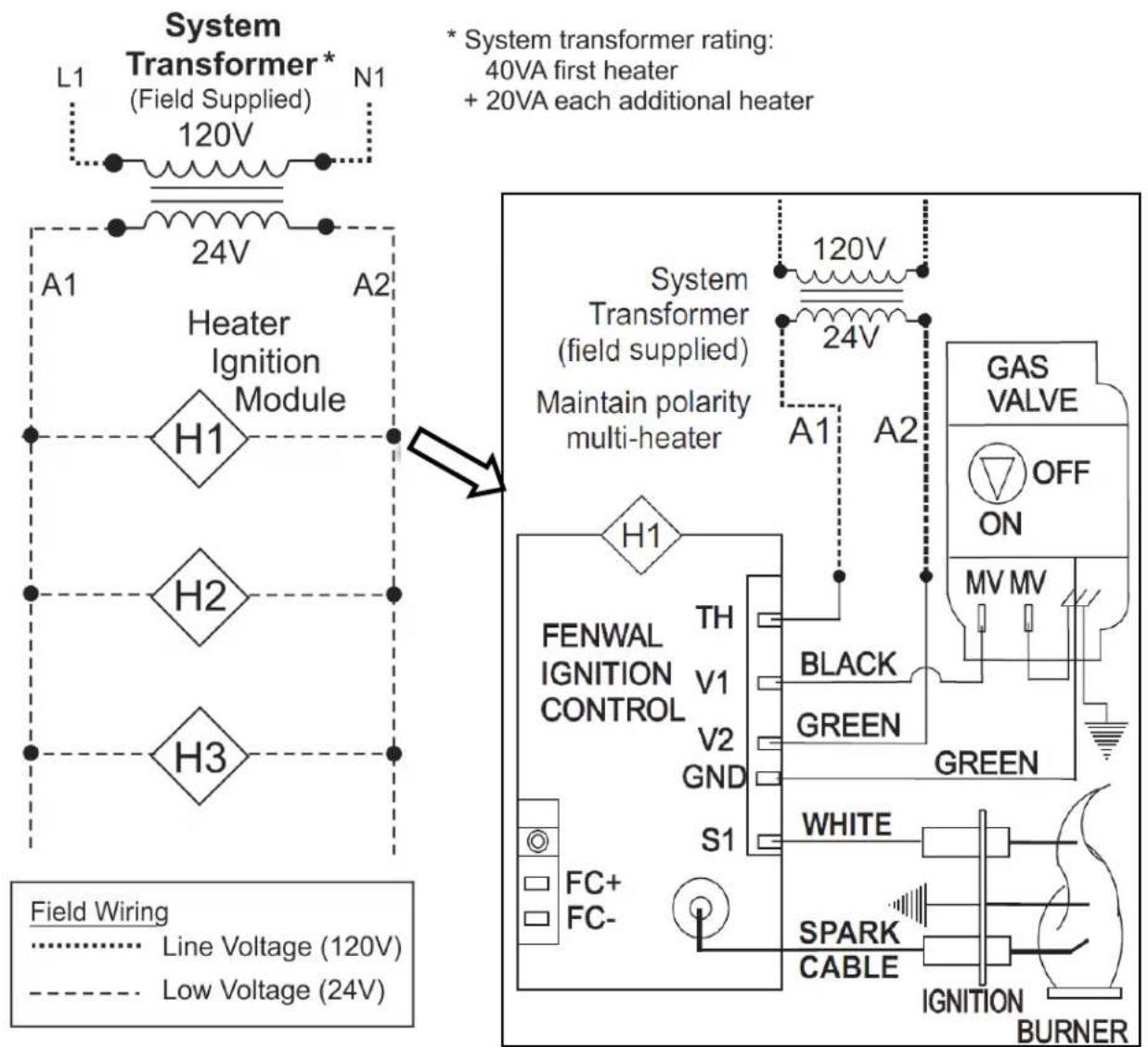
19. WIRING DIAGRAM: SE+ Series with Fenwal 35-60 DSI Control
text_image
System Transformer* (Field Supplied) 120V L1 N1 24V A1 A2 Heater Ignition Module H1 H2 H3 * System transformer rating: 40VA first heater + 20VA each additional heater System Transformer (field supplied) Maintain polarity multi-heater 120V 24V A1 A2 GAS VALVE OFF ON MV MV GREEN FENWAL IGNITION CONTROL TH V1 BLACK V2 GREEN GREEN WHITE SPARK CABLE FC+ FC- ICU S1 BURNER Field Wiring Line Voltage (120V) Low Voltage (24V)Fenwal Control Terminal Designation
TH Thermostat / 24V Supply Input
GND System Ground
V1 Valve Power
V2 24V Supply Neutral
NC Alarm
S1 Remote Flame Sensor
Error Mode LED Indication
Internal Control Failure Steady on
Flame with No Call for 2 flashes heat
Ignition Lockout 3 flashes
Fault Conditions:
The LED will flash on for 1/4 second, then off for 1/4 second during a fault condition. The pause between fault codes is 3 seconds.
19-B. WIRING DIAGRAM: RSEP2S50N Two-Stage: Fenwal 35-60 DSI

text_image
System Transformer* Field Supplied 120Vac 24Vac N1 C 24Vac H1 LO HI H2 LO HI H3 LO HI * System transformer capacity: 40VA first heater + 20VA each additional heater 2-STAGE CONTROL: SWITCH/PLATE ASSEMBLIES 903000006 SINGLE SWITCH/PLATE ASSEMBLY - 2 STAGE PATIO 903000007 DOUBLE SWITCH/PLATE ASSEMBLY - 2 STAGE PATIO 903000008 TRIPLE SWITCH/PLATE ASSEMBLY - 2 STAGE PATIO 2-STAGE CONTROL SWITCH SEQUENCE: OFF-ON-ON N1 120Vac 24Vac LO HI C WHITE L1 FENWAL IGNITION CONTROL TH V1 V2 GND S1 BLACK BLUE GREEN WHITE WHITE FLAME SPARK CABLE OFF ON LO COM HI FLAME SENSE Field Wiring Line Voltage (120V) Low Voltage (24V)Fenwal Control Terminal Designation
| TH | Thermostat / 24V Supply Input |
| GND | System Ground |
| V1 | Valve Power |
| V2 | 24V Supply Neutral |
| NC | Alarm |
| S1 | Remote Flame Sensor |
| Error Mode | LED Indication |
| Internal Control Failure | Steady on |
| Flame with No Call for heat | 2 flashes |
| Ignition Lockout | 3 flashes |
Fault Conditions:
The LED will flash on for 1/4 second, then off for 1/4 second during a fault condition. The pause between fault codes is 3 seconds.
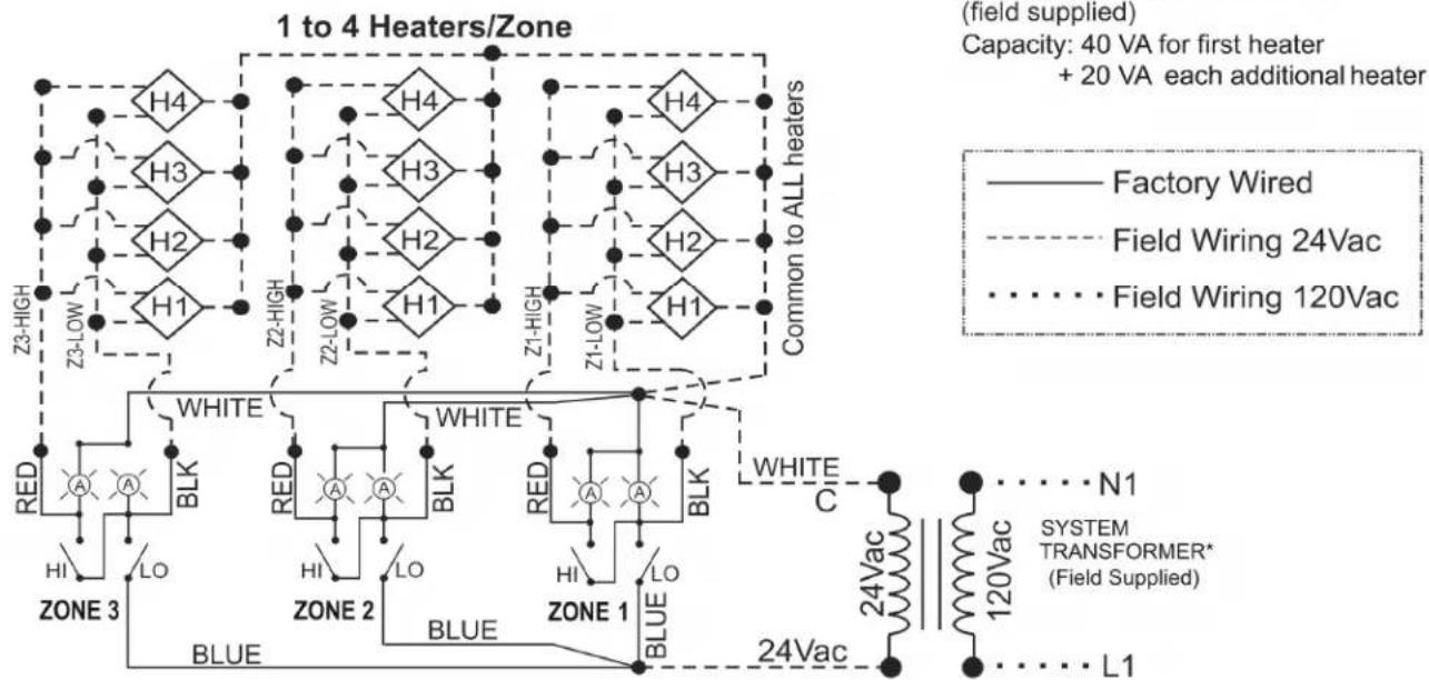
18-C. WIRING DIAGRAM: Two-Stage Switch Control
2-STAGE PATIO CONTROL SWITCH ASSEMBLY WIRING
• Control from 1 to 4 heaters in a zone with each switch
• 2-Stage switch sequence required: OFF-ON-ON
- LOW STAGE SWITCH MUST BE ACTIVATED FOR HIGH STAGE OPERATION
- 3-Wire from first switch provides common (24Vac) to all heaters
2-Wire from additional switches provides low/high stage control

flowchart
graph TD
    subgraph "1 to 4 Heaters/Zone"
        H4["H4"] --> H3["H3"]
        H3 --> H2["H2"]
        H2 --> H1["H1"]
        H1 --> Z2-HIGH["Z2-HIGH"]
        H1 --> Z1-HIGH["Z1-HIGH"]
        H1 --> Z2-LOW["Z2-LOW"]
        H4 --> CommonToALL["Common to ALL heaters"]
    end

    subgraph "1 to 4 Heaters/Zone"
        H4 --> BLK["BLK"]
        H3 --> BLK
        H2 --> BLK
        H1 --> BLK
        BLK --> WHITE["WHITE"]
        BLK --> RED["RED"]
        BLK --> BLK["BLK"]
        WHITE --> C["CLC"]
        RED --> C
        BLK --> C
        BLK --> HI["HI"]
        BLK --> LO["LO"]
        BLK --> ZONE2["ZONE 2"]
        BLK --> BLUE["BLUE"]
        BLK --> ZONE1["ZONE 1"]
        BLK --> ZONE2
        BLK --> ZONE1
        BLK --> ZONE2
    end

    subgraph "90300006 SINGLE SWITCH ASSEMBLY"
        N1["N1"] --> SYSTEM["SYSTEM TRANSFORMER* (Field Supplied)"]
        N1 --> L1["L1"]
        N1 --> 120Vac["120Vac"]
        N1 --> 24Vac["24Vac"]
        N1 --> 24Vac["24Vac"]
        120Vac --> 120Vacn["120Vacn"]
        24Vacn --> 24Vacn
    end
903000007 DOUBLE SWITCH ASSEMBLY
flowchart
graph TD
    subgraph "1 to 4 Heaters/Zone"
        H4["H4"] --> H3["H3"]
        H3 --> H2["H2"]
        H2 --> H1["H1"]
        H1 --> Z3-HIGH
        H1 --> Z2-HIGH
        H1 --> Z2-HIGH
        H1 --> Z2-HIGH
        H1 --> Z2-HIGH
        H1 --> Z2-HIGH
    end

    subgraph "Common to ALL heaters"
        H4["H4"] --> H3["H3"]
        H3 --> H2["H2"]
        H2 --> H1["H1"]
        H1 --> Z3-HIGH
        H1 --> Z2-HIGH
        H1 --> Z2-HIGH
        H1 --> Z2-HIGH
    end

    subgraph "TYPE" (Zone 1-Z3-HIGH)
        A["RED"] --> BLK["BLK"]
        BLK --> HI["HI"]
        BLK --> LO["LO"]
        BLK --> BLUE["BLUE"]
        BLK --> ZONE_3["ZONE 3"]
    end

    subgraph "TYPE" (Zone 2)
        A["A"] --> BLK
        BLK --> HI
        BLK --> LO
        BLK --> BLUE
        BLK --> ZONE_2["ZONE 2"]
    end

    subgraph "TYPE" (Zone 1)
        A["A"] --> BLK
        BLK --> HI
        BLK --> LO
        BLK --> BLUE
        BLK --> ZONE_1["ZONE 1"]
    end

    subgraph "TYPE" (Zone 3)
        C["WHITE"] --> BLK
        BLK --> HI
        BLK --> LO
        BLK --> BLUE
        BLK --> ZONE_1
    end

    subgraph "TYPE" (Zone 1)
        C["C"] --> BLK
        BLK --> HI
        BLK --> LO
        BLK --> BLUE
        BLK --> ZONE_1
    end

    subgraph "TYPE" (Zone 1)
        C["C"] --> BLK
        BLK --> HI
        BLK --> LO
        BLK --> BLUE
        BLK --> ZONE_1
    end

    subgraph "TYPE" (Zone 2)
        C["C"] --> BLK
        BLK --> HI
        BLK --> LO
        BLK --> BLUE
        BLK --> ZONE_2
    end

    subgraph "TYPE" (Zone 3)
        C["C"] --> BLK
        BLK --> HI
        BLK --> LO
        BLK --> BLUE
        BLK --> ZONE_2
    end

    subgraph "TYPE" (Zone 3)
        C["C"] --> BLK
        BLK --> HI
        BLK --> LO
        BLK --> BLUE
        BLK --> ZONE_3
    end

    subgraph "TYPE" (Zone 1)
        C["C"] --> BLK
        BLK --> HI
        BLK --> LO
        BLK --> Blue
        Blue --> ZONE_1
    end

    subgraph "TYPE" (Zone 1)
        C["C"] --> BLK
        BLK --> HI
        BLK --> LO
        Blue --> ZONE_2
    end

    subgraph "TYPE" (Zone 1)
        C["C"] --> BLK
        BLK --> HI
        Blue --> LO
    end

    note right of "Capacity: 40 VA for first heater + 20 VA each additional heater"
    note right of "Field Supplied"
    note right of "SYSTEM TRANSFORMER* (Field Supplied)"
903000008 TRIPLE SWITCH ASSEMBLY
*SYSTEM TRANSFORMER
(field supplied)
Capacity: 40 VA for first heater
+ 20 VA each additional heater
Factory Wired
Field Wiring 24Vac
Field Wiring 120Vac
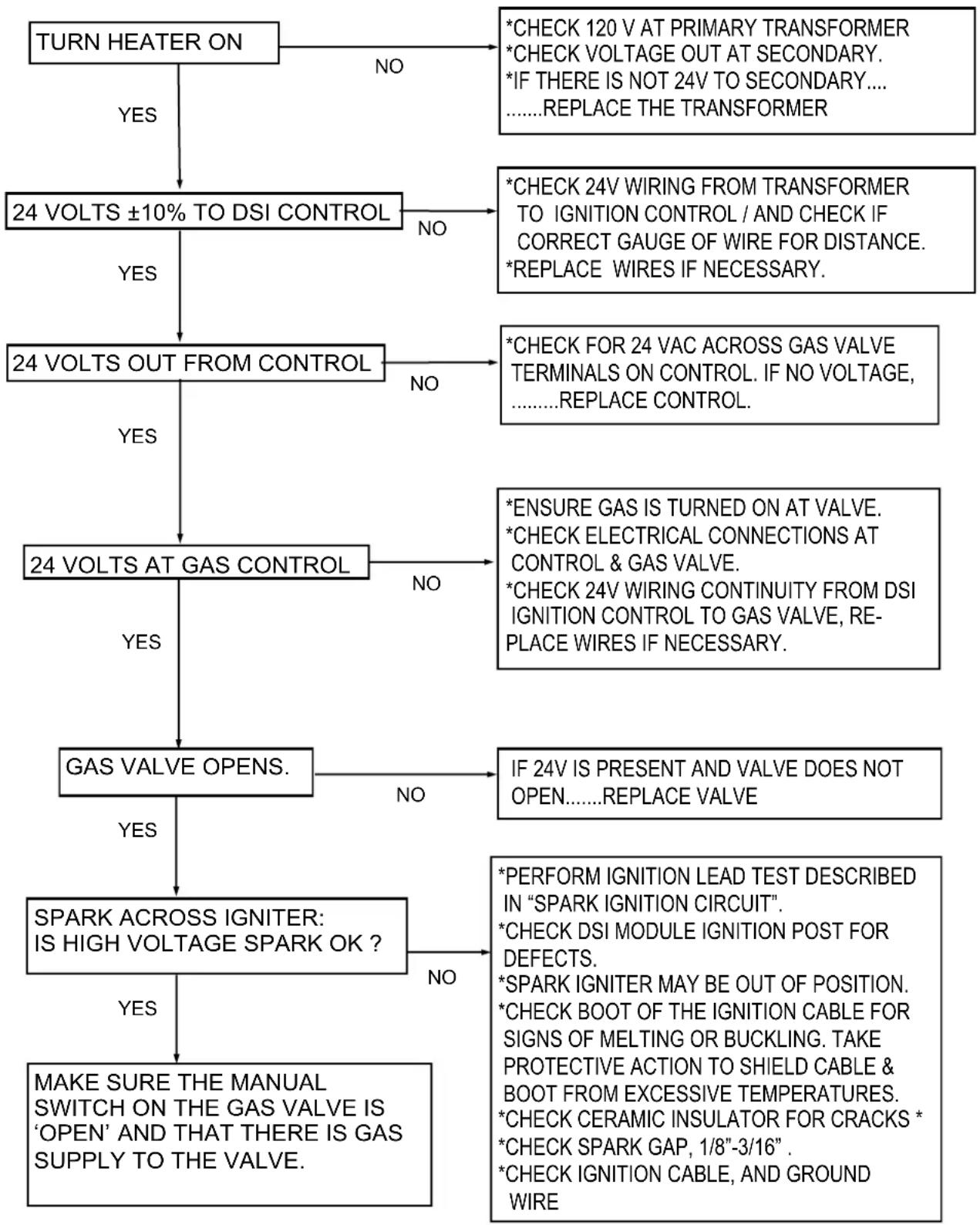
20. TROUBLESHOOTING GUIDE
flowchart
graph TD
    A["TURN HEATER ON"] -->|YES| B["24 VOLTS ±10% TO DSI CONTROL"]
    A -->|NO| C["*CHECK 120 V AT PRIMARY TRANSFORMER\n*CHECK VOLTAGE OUT AT SECONDARY.\n*IF THERE IS NOT 24V TO SECONDARY....\n......REPLACE THE TRANSFORMER"]
    B -->|YES| D["24 VOLTS OUT FROM CONTROL"]
    B -->|NO| E["*CHECK 24V WIRING FROM TRANSFORMER\nTO IGNITION CONTROL / AND CHECK IF\nCORRECT GAUGE OF WIRE FOR DISTANCE.\n*REPLACE WIRES IF NECESSARY."]
    D -->|YES| F["24 VOLTS AT GAS CONTROL"]
    D -->|NO| G["*CHECK FOR 24 VAC ACROSS GAS VALVE\nTERMINALS ON CONTROL. IF NO VOLTAGE,\n......REPLACE CONTROL."]
    F -->|YES| H["GAS VALVE OPENS."]
    F -->|NO| I["*ENSURE GAS IS TURNED ON AT VALVE.\n*CHECK ELECTRICAL CONNECTIONS AT\nCONTROL & GAS VALVE.\n*CHECK 24V WIRING CONTINUITY FROM DSI\nIGNITION CONTROL TO GAS VALVE, RE-\nPLACE WIRES IF NECESSARY."]
    H -->|YES| J["SPARK ACROSS IGNITER:\nIS HIGH VOLTAGE SPARK OK ?"]
    H -->|NO| K["IF 24V IS PRESENT AND VALVE DOES NOT\nOPEN......REPLACE VALVE"]
    J -->|YES| L["MAKE SURE THE MANUAL SWITCH ON THE GAS VALVE IS 'OPEN' AND THAT THERE IS GAS SUPPLY TO THE VALVE."]
    J -->|NO| M["*PERFORM IGNITION LEAD TEST DESCRIBED\nIN "SPARK IGNITION CIRCUIT".\n*CHECK DSI MODULE IGNITION POST FOR DEFECTS.\n*SPARK IGNITER MAY BE OUT OF POSITION.\n*CHECK BOOT OF THE IGNITION CABLE FOR\nSIGNS OF MELTING OR BUCKLING. TAKE PROTECTIVE ACTION TO SHIELD CABLE &\nBOOT FROM EXCESSIVE TEMPERATURES.\n*CHECK CERAMIC INSULATOR FOR CRACKS *\n*CHECK SPARK GAP, 1/8"-3/16".\n*CHECK IGNITION CABLE, AND GROUND WIRE"]
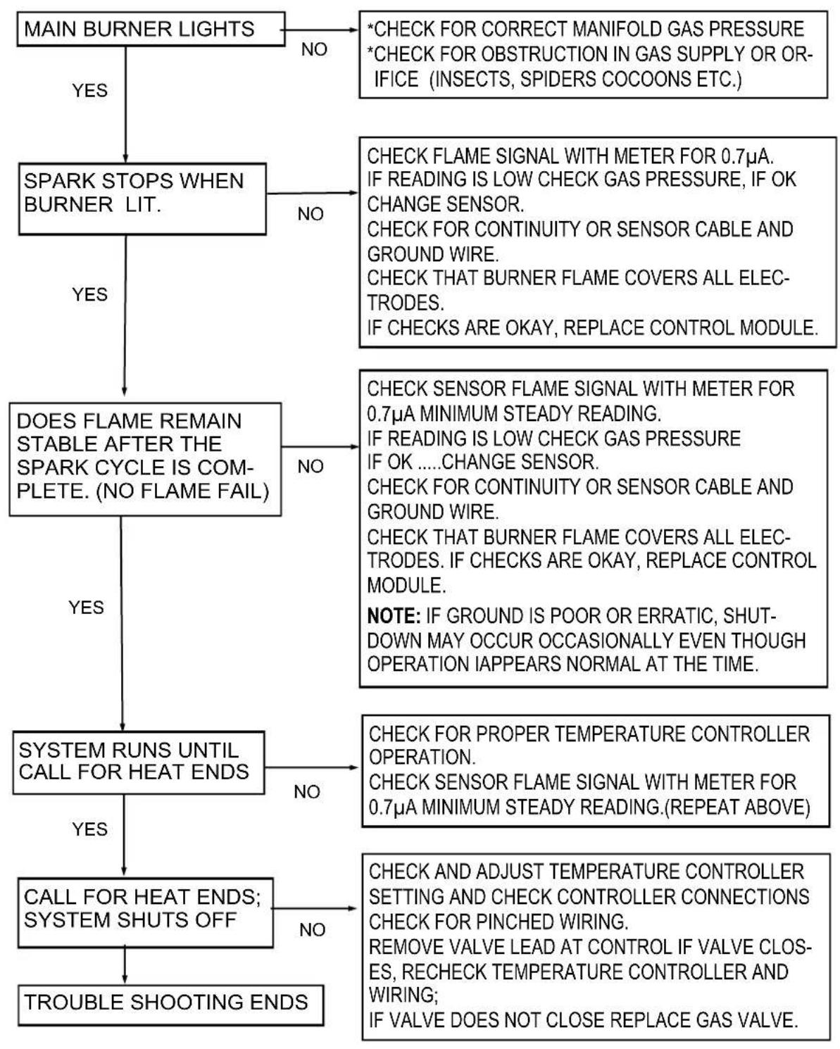
flowchart
graph TD
    A["MAIN BURNER LIGHTS"] -->|YES| B["SPARK STOPS WHEN BURNER LIT."]
    A -->|NO| C["*CHECK FOR CORRECT MANIFOLD GAS PRESSURE\n*CHECK FOR OBSTRUCTION IN GAS SUPPLY OR OR-IFICE (INSECTS, SPIDERS COCOONS ETC.)"]
    B -->|YES| D["DOES FLAME REMAIN STABLE AFTER THE SPARK CYCLE IS COMPLETE. (NO FLAME FAIL)"]
    B -->|NO| E["CHECK FLAME SIGNAL WITH METER FOR 0.7μA.\nIF READING IS LOW CHECK GAS PRESSURE, IF OK\nCHANGE SENSOR.\nCHECK FOR CONTINUITY OR SENSOR CABLE AND\ngROUND WIRE.\nCHECK THAT BURNER FLAME COVERS ALL ELECTRODES.\nIF CHECKS ARE OKAY, REPLACE CONTROL MODULE."]
    C -->|YES| F["SYSTEM RUNS UNTIL CALL FOR HEAT ENDS"]
    C -->|NO| G["CHECK SENSOR FLAME SIGNAL WITH METER FOR 0.7μA MINIMUM STEADY READING.\nIF READING IS LOW CHECK GAS PRESSURE\nIF OK .....CHANGE SENSOR.\nCHECK FOR CONTINUITY OR SENSOR CABLE AND\ngROUND WIRE.\nCHECK THAT BURNER FLAME COVERS ALL ELECTRODES. IF CHECKS ARE OKAY, REPLACE CONTROL MODULE.\nNOTE: IF GROUND IS POOR OR ERRATIC, SHUT-DOWN MAY OCCUR OCCASIONALLY EVEN THOUGH OPERATION IAPPEARS NORMAL AT THE TIME."]
    F -->|YES| H["CALL FOR HEAT ENDS;\nSYSTEM SHUTS OFF"]
    F -->|NO| I["CHECK FOR PROPER TEMPERATURE CONTROLLER OPERATION.\nCHECK SENSOR FLAME SIGNAL WITH METER FOR 0.7μA MINIMUM STEADY READING.(REPEAT ABOVE)."]
    H -->|YES| J["TROUBLE SHOOTING ENDS"]
    H -->|NO| K["CHECK AND ADJUST TEMPERATURE CONTROLLER SETTING AND CHECK CONTROLLER CONNECTIONS\nCHECK FOR PINCHED WIRING.\nREMOVE VALVE LEAD AT CONTROL IF VALVE CLOS-ES, RECHECK TEMPERATURE CONTROLLER AND WIRING;\nIF VALVE DOES NOT CLOSE REPLACE GAS VALVE."]
NOTE: IF CONTROL GOES INTO LOCKOUT, THE SYSTEM CAN BE RESET BY INTERRUPTING THE POWER SOURCE
21. COMMISSIONING REPORT
This heater has been factory fired and tested prior to shipment. However, it is not a 'Plug-in' appliance. Commissioning and field adjustment to correct settings is required.
COMPLETE THIS COMMISSIONING REPORT AND FILE THIS MANUAL AT SITE FOR FUTURE REFERENCE
INSTRUCT THE END USER THAT THIS MANUAL MUST BE KEPT SECURE
COMMISSIONING REPORT AS PER I&O MANUAL AND LOCAL/NATIONAL CODES
CONTRACTOR:
STREET:
CITY: ____ STATE/PROV: ____ ZIP: ____
PHONE: ____ CELL: ____
JOBE NAME:
CITY: STATE/PROV:
HEATER MODEL NUMBER :
Located on burner rating plate
HEATER SERIAL NUMBER :
Located on burner rating plate
Technical commissioning report continues next page ....
HEATER COMMISSIONING TECHNICAL REPORT TO BE COMPLETED BY QUALIFIED GAS FITTER INSTALLER
TYPE OF GAS NG
HEATER IS EXPOSED TO CHENICAL OR CORROSIVE ATMOSPHERE
OPEN COMBUSTION IS COMPATIBLE WITH THE INSTALLED LOCATION
MINIMUM CLEARANCES CONFORM TO REQUIREMENTS OF THIS MANUAL
WHAT IS THE ALTITUDE OF THIS PROJECT LOCATION ABOVE SEA LEVEL
■ IS ALTITUDE ADJUSTMENT REQUIRED? (See Section 21 next page)
THE HEATER IS INSTALLED LEVEL ON THE LONG AXIS
THE GAS SUPPLY PIPING IS ADEQUATELY SIZED FOR SYSTEM VOLUME
GAS SUPPLY LINES AND BRANCHES HAVE BEEN PURGED OF AIR
INLET GAS SUPPLY PRESSURE WITH ALL HEATERS OPERATING
MANIFOLD PRESSURE WITH HEATER OPERATING
WIRING POLARITY IS MAINTAINED AT EACH IGNITION MODULE IN SYSTEM
VOLTAGE READING AT IGNITION MODULE
FLAME SIGNAL STRENGTH FROM SENSOR ( A microamps)
IS THE HEATER CONTROLLED BY A THERMOSTAT
IS THE THERMOSTAT STRATEGICALLY LOCATED
QUANTITY OF HEATERS IN ZONE SUPPLIED BY SINGLE TRANSFORMER
RATING OF THE ZONE TRANSFORMER (VA Volt-Amps)
TOTAL LENGTH OF LOW VOLTAGE WIRING
GAUGE OF THE LOW VOLTAGE WIRING
IS THE HEATER ELECTRICALLY GROUNDED
THIS HEATER TEST FIRED WITHOUT MALFUNCTION

text_image
LP YES NO YES NO YES NO FEET YES NO YES NO YES NO "WC" "WC YES NO VOLTS µA YES NO YES NO Total VA FEET GAUGE YES NO YES NO- COMPLETE THIS COMMISSIONING REPORT AND FILE THIS MANUAL AT SITE FOR FUTURE REFERENCE
- INSTRUCT THE END USER THAT THIS MANUAL MUST BE KEPT SECURE
22. HIGH ALTITUDE INSTALLATION / DERATION
This heater not to be installed at altitude above 6,800 feet.
USA: The factory installed orifice for this appliance is approved for altitudes zero to 2000 feet above sea level. When installed above 2000 feet, refer to information below.
When this appliance is installed above the standard altitude stipulated the input must be de-rated by 4% for each 1000 ft above sea level. The orifice must be changed according to the chart below - confirm the correct model. Check with your local utility regarding the gas supply and the de-rating of this appliance.
| MODEL | USA ORIFICE DERATIONFOR USE AT ALTITUDES ABOVE (FEET)Gas Orifice Drill Size ^1 / Part # | ||||||
| Supplied | USA Only | ||||||
| 0 | >2000 | >3000 | >4000 | >5000 | >6000 | DO NOTINSTALL ATALTITUDE ABOVE6,800 FEET | |
| RSEP1S25N (NG) | 45 DMS906000140 | 46 DMS906000141 | 2 MM906000153 | 47 DMS906000163 | 48 DMS906000164 | 48 DMS906000164 | |
| RSEP1S25P (LPG) | 54 DMS906000144 | 54 DMS906000144 | 55 DMS906000170 | 55 DMS906000170 | 55 DMS906000170 | 55 DMS906000170 | |
| RSEP1S35N (NG) | 38 DMS906000025 | 39 DMS906000157 | 40 DMS906000138 | 41 DMS906000159 | 41 DMS906000159 | 42 DMS906000160 | |
| RSEP1S35P (LPG) | 50 DMS906000026 | 51 DMS906000142 | 51 DMS906000142 | 51 DMS906000142 | 51 DMS906000142 | 52 DMS906000167 | |
| RSEP2S50N (NG) | 31 DMS906000137 | 32 DMS906000154 | 32 DMS906000154 | 32 DMS906000154 | 33 DMS906000155 | 34 DMS906000156 | |
^1 Per ANSI Z223.1 (NFPA 54)
23. Replacement Parts List
Only the following illustrated parts are available. For any other parts please contact Rinnai.
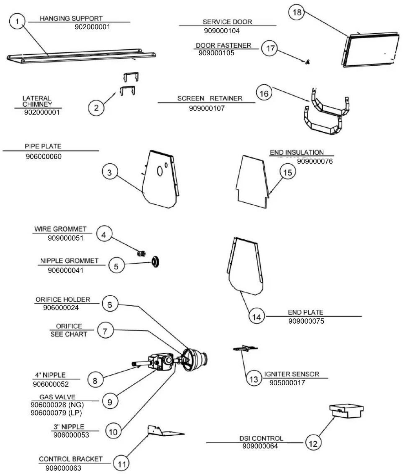
text_image
HANGING SUPPORT 902000001 SERVICE DOOR 909000104 DOOR FASTENER 909000105 LATERAL CHIMNEY 902000001 SCREEN RETAINER 909000107 PIPE PLATE 906000060 END INSULATION 909000076 WIRE GROMMET 909000051 NIPPLE GROMMET 906000041 ORIFICE HOLDER 906000024 ORIFICE SEE CHART 4" NIPPLE 906000052 GAS VALVE 906000028 (NG) 906000079 (LP) 3" NIPPLE 906000053 CONTROL BRACKET 909000063 END PLATE 909000075 IGNITER SENSOR 905000017 DSI CONTROL 90900006423. Replacement Parts List Con't
Replacement parts for the RSEP2S50N 2 stage (50,000/35,000 Btu/hr)
| Item Number(page 35) | Part Description Part Number | |
| 8 | 6" Nipple | 906000030 |
| 9 2 Stage | Gas Valve 906000149 | |
| 10 | 2" Nipple With Hole | 906000027 |
| 11 | 2 Stage Control Bracket | 909000142 |
| 13 | Pilot Burner Assembly | 906000032 |
| Pilot Gas Tube Assembly | 906000135 | |
| Pilot Nipple Ferrule 906000152 | ||
| Flame Sensor 906000034 | ||
| 14 | Extended End Plate | 903000004 |
| 16 | Extended Screen Retainer | 903000005 |
NOTES
NOTES
NOTES
Rinnai America Corporation
103 International Drive
Peachtree City, GA 30269
Tel. 1-800-621-9419
Web. www.rinnai.us
www.rinnai.ca
900000018
2/2021