LA1500RTR - Monitor Planar - Free user manual and instructions
Find the device manual for free LA1500RTR Planar in PDF.

User questions about LA1500RTR Planar
0 question about this device. Answer the ones you know or ask your own.
Ask a new question about this device
Download the instructions for your Monitor in PDF format for free! Find your manual LA1500RTR - Planar and take your electronic device back in hand. On this page are published all the documents necessary for the use of your device. LA1500RTR by Planar.
USER MANUAL LA1500RTR Planar
The information contained in this document is subject to change without notice. This document contains proprietary information that is protected by copyright. All rights are reserved. No part of this document may be reproduced, translated to another language or stored in a retrieval system, or transmitted by any means, electronic, mechanical, photocopying, recording, or otherwise, without prior written permission.
Windows is a registered trademark of Microsoft, Inc.
Other brands or product names are trademarks of their respective holders.
European Union 2002/95/EC Directive on the Restriction of Hazardous Substances (RoHS)
In February 2003, the European Union issued Directive 2002/95/EC on the Restriction of Hazardous Substances, commonly known as RoHS, in certain electrical and electronic equipment. It restricts the use of six hazardous substances, including lead (Pb).
The Directive states that all new products within its scope, placed on the European market after July 1, 2006 must be compliant with its requirements.
Planar Systems Inc. is fully in support of and compliant with EU Directive 2002/95/EC for applicable products within its scope.
A Planar part number will be modified with an "LF" suffix designation to indicate RoHS compliance, as shown on the part number label affi xed to the display and on the box containing the display.
Important Recycle Instruction:

LCD Lamp(s) inside this product contain mercury. This product may contain other electronic waste that can be hazardous if not disposed of properly. Recycle or dispose in accordance with local, state, or federal Laws. For more information, contact the Electronic Industries Alliance at WWW.EIAE.ORG. For lamp specific disposal information check WWW.LAMPRECYCLE.ORG.
Revision Control
DATE: DESCRIPTION:
March 2004 Document number 020-0319-00A
March 2005 Document number 020-0319-00B
June 2006 Document number 020-0319-01A
Contents
Usage Notice
Precautions....4
Introduction
About the Product ....5
Package Overview ....8
Installation
Product Overview....9
User Controls
Front Panel Controls 13
How to Use the OSD Menus 14
On-Screen Display Menus 15
Appendix
Troubleshooting....18
Warning Signal 19
Product Dimensions 20
Video Modes.... 24
Touch Screen Driver Installation 25
Support and Service 28
Usage Notice

WARNING – To prevent the risk of fire or shock hazards, do not expose this product to rain or moisture.

WARNING – Please do not open or disassemble the product as this may cause electric shock.
Precautions
Follow all warnings, precautions and maintenance as recommended in this user's guide to maximize the life of your unit.
Do:
☐ Turn off the product before cleaning.
☐ LCD front surface may be cleaned using a soft clean cloth moistened with mild window glass commercial cleaners or 50/50 mixture of water and isopropyl alcohol.
☐ Use only high quality and safety approved AC/DC power adapter that comes with your monitor.
☐ Disconnect the power plug from AC outlet if the product is not used for an extended period of time.
Don't:
☐ Do not touch the LCD display screen surface with sharp or hard objects.
☐ Do not use abrasive cleaners, waxes or solvents for cleaning.
☐ Do not operate the product under the following conditions:
- Extremely hot, cold or humid environment.
- Areas susceptible to excessive dust and dirt.
- Near any appliance generating a strong magnetic field.
- In direct sunlight.
Introduction
About Planar's LA1500R / LA1500RTR / LA1500RTC
The LA15 products all have a 15" fl at panel screen with an active matrix, thin-fi lm transistor (TFT) liquid crystal display (LCD).
Features include:
☐ Direct analog graphics signal input
☐ Active matrix TFT LCD technology
☐ 1024 x 768 XGA resolution
☐ 15" viewable display area
☐ 31.5 \~ 60 kHz horizontal scan
☐ 56 \~ 75 Hz refresh rate
☐ 0.297mm x 0.297mm pixel pitch
☐ 350 cd/m²(typ.)brightness
☐ 400:1(typ.) contrast ratio
☐ L/R=75°/75°, U/D=+50°/-75° viewing angle, CR=5
☐ Tr=4ms(typ.)/tf=12ms(typ.) response time
☐ 2 Cold cathode Flourescent Lamps (CCFL) with 50,000 hrs life
□ Auto-adjustment function
□ Multilingual OSD user controls
□ VESA DPMS power saving
☐ Durable touchscreen
☐ VESA rear mounting 75mm x 75mm standard
Touch Screen for LA1500RTR
Resistive for finger and pen interface
Surface: Anti-glare treatment
Interface: USB
☐ Durability: 35 million touches at a single point
☐ Hardness: 4H per ASTM D3363-92
☐ Operating force: Stylus - < 25g (average)
Finger - < 50g (average)
☐ Transmissivity: 80% (typ.) +/- 2%
Haze: 5%
Clarity: 80%
Driver: Windows® 95/98/Me/NT/2000/XP, Linux
Touch Screen for LA1500RTC
Capacitive for finger interface
Surface: Anti-glare treatment
Interface: USB
☐ Durability: 225 million touches in a single location
- Hardness: Cannot be scratched using any stylus with Mohr's rating of less than 6.5
☐ Transmissivity: up to 88% at 550 nm
Driver: Windows® 95/98/Me/NT/2000/XP, Linux
Package Overview

natural_image
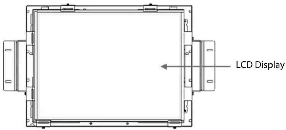
Technical line drawing of a rectangular frame with mounting flanges and bolt holes (no text or symbols)LCD Display

natural_image
Line drawing of a cable and connector with a rectangular device (no text or symbols)Power Adapter

natural_image
Line drawing of a cord with attached plug and connector (no text or symbols)Power Cord
natural_image
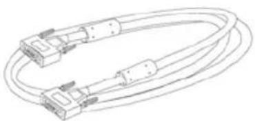
Line drawing of two coaxial cable connectors with connectors and cables (no text or symbols)VGA Signal Cable

Landing Strip
Touch Screen Driver Installation CD-ROM (for LA1500RTR/ LA1500RTC)

USB Cable (for LA1500RTR/ LA1500RTC)
Installation
Product Overview
- Front View
text_image
LCD Display- Rear View

text_image
Connector Ports "A" Connector Ports "B"- Connector Ports "A"
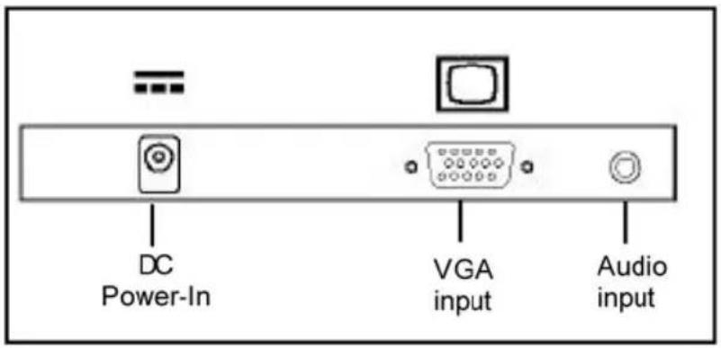
text_image
DC Power-In VGA input Audio input- Connector Ports "B"
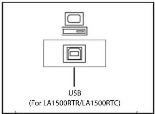
text_image
USB (For LA1500RTR/LA1500RTC)Connecting the display (Figure 1.1)
To set up this display, please refer to the following figure and procedures.
- Be sure all equipment is off.
- Connect the DC power cord to the power connector. Plug one end of the AC power cord into the power adapter, and the other end into an electrical outlet(1).
- For the PC with Analog graphics output: connect the VGA signal cable from display VGA input connector to the 15-pin VGA connector of your host computer and tighten the screws(2).
- For the LA1500RTR or the LA1500RTC touch screen models configure the touch screen. Refer to the "Touch Screen Driver Installation" section on page 25.
- Turn on your computer, display and video source.
Notice: To ensure the LCD display works well with your computer, configure the display mode of your graphic card to less than or equal to 1024 x 768 resolution and make sure timing of the display mode is compatible with the LCD panel. "Video Modes" of this LCD panel are listed in the appendices for your reference.
Figure 1.1

natural_image
Top-down schematic of a mechanical or architectural component with symmetrical cutouts and central circular feature (no text or symbols)
flowchart
graph TD
    A["Server"] -->|① Power Adapter & Power Cord| B["Switch"]
    B --> C["USB Cable"]
    C --> D["Device 1"]
    D --> E["Switch"]
    E --> F["Device 2 VGA Cable"]
    F --> G["Switch"]
    G --> H["Device 3 USB Cable"]
User Controls Front Panel Controls
natural_image
Pure technical line drawing of a rectangular frame with mounting flanges (no text or symbols)
text_image
⑥ ⑤ ④ ③ ② ①| No./ Icon | Control | Function |
| 1 | Menu button Displays the OSD menus. | |
| 2 | Select / Auto | Select- To select the adjustment items from OSD menus.Auto- To activate the “Auto Adjustment” function to obtain an optimum image. |
| 3 | Brightness Minus / Minus | 1. Decreases the brightness of the display image.2. Decreases value of the adjustment items. |
| 4 | Brightness Plus / Plus | 1. Increases the brightness of the display image.2. Increases value of the adjustment items. |
| 5 | Power Switch | Switches on/off the power of the LCD display. |
| 6 | Power LED | 1. Green indicates the display is turned on.2. Amber indicates the display is in power-saving mode. |
How to Use the OSD Menus
- Press the "Menu" button to pop up the on-screen menu and to select between the four main menus.
- Choose the adjustment items by pressing the "Select/Auto" button.
- Adjust the value of the adjustment items by pressing the "☐" button.
- The OSD menu will automatically close, if you have left it idle for a pre-set amount of time.
On-Screen Display Menus
Main OSD Menu:
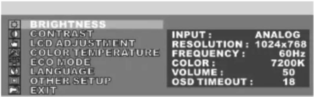
text_image
BRIGHTNESS CONTRAST LCD ADJUSTMENT COLOR TEMPERATURE ECO MODE LANGUAGE OTHER SETUP EXIT INPUT: ANALOG RESOLUTION: 1024x768 FREQUENCY: 60Hz COLOR: 7200K VOLUME: 50 OSD TIMEOUT: 18◆ Brightness
Choose this function to adjust the brightness of the image.
Contrast
Choose this function to adjust the contrast of the image.
◆ LCD Adjustment
Opens the LCD Adjustment sub-menu where you can adjust the Clock, Phase, Horizontal Position and Vertical Position parameters.
◆ Color Temperature
Opens the Color Temperature sub-menu where you can select the desired Color Temperature of the image.
ECO Mode
Enables or disables the power savings mode.
Language
Opens the Language sub-menu where you can select the desired language of the OSD.
◆ Other Setup
Opens the Other Setup sub-menu where you can adjust the Smooth, OSD Position, OSD Transparency, OSD Time Out, Volume and Mode Message parameters.
On-Screen Display Menus
LCD Adjustment Sub-Menu:
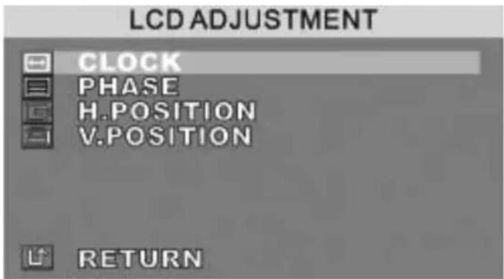
text_image
LCD ADJUSTMENT CLOCK PHASE H.POSITION V.POSITION RETURN◆ Clock
Minimizes any vertical bars or stripes visible on the screen.
◆ Phase
Minimizes any horizontal distortion and clears or sharpens the displayed characters.
◆ Horizontal Position
Changes the horizontal position of the image.
◆ Vertical Position
Changes the vertical position of the image.
On-Screen Display Menus
Other Setup Sub-Menu:

text_image
OTHER SETUP SMOOTH OSD H. POSITION OSD V. POSITION OSD TRANSPARENCY OSD TIMEOUT VOLUME MODE MESSAGE RESET RETURN◆ Smooth
Adjusts the smoothness of the image.
◆ OSD Horizontal Position
Changes the horizontal position of the OSD.
◆ OSD Horizontal Position
Changes the horizontal position of the OSD.
◆ OSD Vertical Position
Changes the vertical position of the OSD.
◆ OSD Transparency
Changes the opaqueness of the OSD background.
◆ OSD Time out
Adjusts the amount of time the OSD menu will be displayed for after inactivity.
Volume
Adjusts the sound volume.
◆ Mode Message
Enables or disables the display of information.
◆ Reset
Resets the display parameters back to its factory default settings.
Appendix
Troubleshooting
If you are experiencing trouble with the LCD display, refer to the following. If the problem persists, please contact your local dealer or visit Planar Support at www.planar.com/support. See support contact information on rear cover.
Problem: No image appears on screen.
◆ Check that all the I/O and power connectors are installed correctly and well connected as described in the “Installation” section.
◆ Make sure the pins of the connectors are not crooked or broken.
◆ Reconfigure the resolution of your computer to make it less than or equal to 1024 x 768.
Problem: Partial image or incorrectly displayed image.
◆ Check to see if the resolution of your computer is higher than that of the LCD display.
◆ Reconfigure the resolution of your computer to make it less than or equal to 1024 x 768.
Problem: Image has fl ickering vertical line bars.
◆ Use "Clock" to make an adjustment.
◆ Check and reconfigure the display mode of the vertical refresh rate of your graphic card to make it compatible with the LCD display.
Problem: Image is unstable and fl ickering
◆ Use "Phase" to make an adjustment.
Problem: Image is scrolling
◆ Check and make sure the VGA signal cable (or adapter) is well connected.
◆ Check and reconfigure the display mode of the vertical refresh rate of your graphic card to make it compatible with the LCD display.
Problem: Ghosting image (characters and graphics)
◆ Use "Clock" to make an adjustment. If the problem persists, use "Phase" to make an adjustment.
Warning Signal
If you see warning messages on your LCD screen, this means that the LCD display cannot receive a clean signal from the computer graphics card.
There may be three sources for this problem. Please check the cable connections or contact Planar for more information.
◆ No Signal
This message means that the LCD display has been powered on but it cannot receive any signal from the computer graphic card. Check all the power switches, power cables, and VGA signal cable.
◆ Going to Sleep
This message means that the LCD display is under the power saving mode. In addition, the LCD display will enter the sleep mode when experiencing a sudden signal disconnecting problem.
◆ Out of Range
This message means that the signal of the computer graphic card is not compatible with the LCD display. When the signal is not included in the “Video Modes” list we have listed in the Appendices of this manual, the LCD display will display this message.
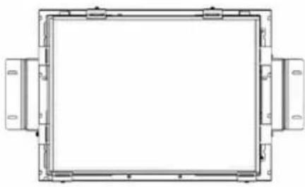
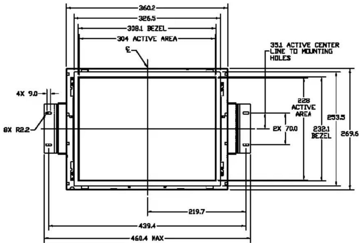
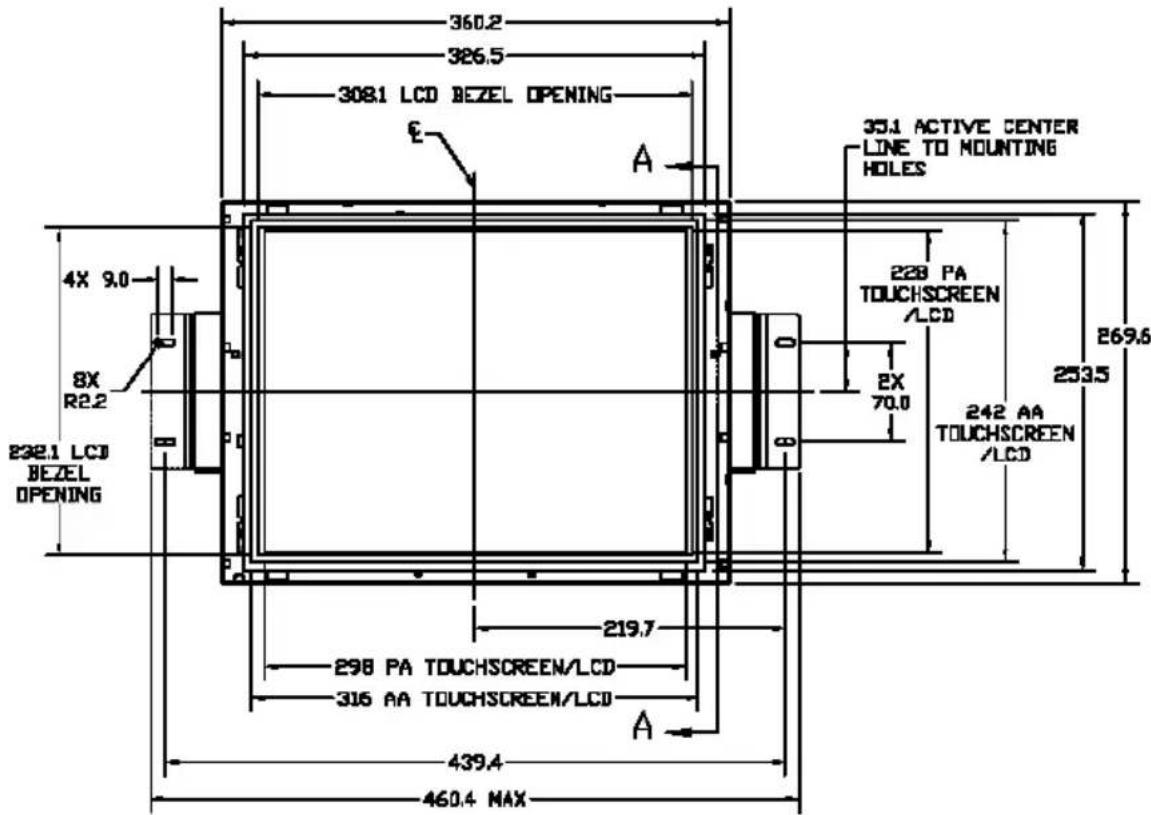
Product Dimensions
LA1500RTR - Front View:

text_image
360.2 326.5 308.1 LCD BEZEL OPENING E A 35.0 ACTIVE CENTER LINES TO MOUNTING HOLES 4X 9.0 8X R2.2 232.1 LCD BEZEL OPENING 228 AA TOUCHSCREEN /LCD 2X 70.0 232 VA TOUCHSCREEN /LCD 259.6 253.5 219.7 304 AA TOUCHSCREEN/LCD 308 VA TOUCHSCREEN/LCD A 439.4 460.4 MAXLA1500RTR Front View
LA1500R - Front and Side View:
text_image
360.2 326.5 308.1 BEZEL 304 ACTIVE AREA E 4X 9.0 8X R2.2 351 ACTIVE CENTER LINE TO MOUNTING HOLES 228 ACTIVE AREA 2X 70.0 232.1 BEZEL 253.5 269.6 219.7 439.4 460.4 MAXLA1500R Front View

text_image
LA1500R Side View 84.7 MAX W/BRACKET 2X 42.0 8X R2.2 64.0 64.0 110.0 2X 90.0 13.1 0.7 4X 10.5 44.9LA1500R, LA1500RTR and LA1500RTC User's Guide (020-0319-01 Rev. A)
LA1500RTC - Front and Side View:
text_image
360.2 326.5 308.1 LCD BEZEL OPENING E A 35.1 ACTIVE CENTER LINE TO MOUNTING HOLES 4X 9.0 8X R2.2 232.1 LCD BEZEL OPENING 228 PA TOUCHSCREEN /LCD 253.5 242 AA TOUCHSCREEN /LCD 219.7 298 PA TOUCHSCREEN/LCD 316 AA TOUCHSCREEN/LCD A 439.4 460.4 MAXLA1500RTC Front View

text_image
22.5 1.5 2X 42.0 90.0 BOTH ENDS 64.00 BOTH ENDS 90.00 BOTH ENDS 13.1 BOTH ENDS 4X 12.0 BOTH ENDS 46.4 85.5 MAX W/BRACKET 8X R2.2 64.0 110.0 4X M2.5 BOTH ENDS LA1500RTC Side View 3M CAPACITIVE TOUCH 1.0 ADHESIVE BETWEEN LCD AND TOUCH SECTION A-ALA1500R/RTR/RTC - Rear View:

text_image
DSD CONTROL 75.0 4X M4 MOUNTING 75.0LA1500R/RTR/RTC Rear View
Video Modes
The monitor supports the following industry-standard combinations of screen resolution and refresh rates. Other combinations are possible, but may require adjustments to the image.
For the optimal performance, set your computer to a screen resolution of 1024 x 768 at a 60 Hz refresh rate.
| Display Mode | Hsync (kHz) | Vsync (Hz) | |
| VGA | 640 x 350 | 31.5 | 70 |
| 640 x 400 | 31.5 | 70 | |
| 640 x 480 | 31.5 | 60 | |
| 37.9 | 72 | ||
| 37.5 | 75 | ||
| SVGA | 800 x 600 | 35.2 | 56 |
| 37.9 | 60 | ||
| 48.1 | 72 | ||
| 46.9 | 75 | ||
| XGA | 1024 x 768 | 48.4 | 60 |
| 56.5 | 70 | ||
| 60 | 75 | ||
| US TEXT | 720 x 400 | 31.5 | 70 |
| Apple MAC | 640 x 480 | 34.9 | 67 |
| 35 | 67 | ||
| 832 x 624 | 49.7 | 75 | |
| 1024 x 768 | 60.2 | 75 | |
Touch Screen Driver Installation
Driver Installation for LA1500RTR:
Resistive Touch Screen with USB Connection
Please note: These monitors are Microsoft Windows® HID (Human Interface Device) compatible. No additional software driver is required for general operation of the touch screen.
A special calibration tool can be installed for improved touch position accuracy. See Optional MicroTouch™ USB HID Calibration Tool version 7.00 Installation Process.
Optional Driver MicroTouch™ USB HID Calibration Tool Version 7.00 Installation Process for LA1500RTR: Resistive Touch Screen with USB Connection
Please note: These monitors are Microsoft HID (Human Interface Device) compatible. The calibration driver is not required for general operation of the touch screen.
This calibration tool is for optimization of touch performance for the touch screen to meet the 1% TPE accuracy specification.
The following Microsoft Windows® operating systems are supported by this software driver: Microsoft Windows® 98SE, Me, 2000, and XP.
- Be sure that the USB cable is not connected to the PC.
- Open the CD-Rom.
- Click the "LA1500RTR, LA1710RTR, PT1500MU/1700MU Calibration Option" link.
- Click "I accept" when the software license screen appears.
- Follow the step-by-step instructions
- Reconnect the USB cable to the computer prior to use.
- If the touch screen driver does not automatically load, restart the computer operating system.
Please read "Readme.txt" located in the unzipped file folder for additional information and assistance.
Driver Installation for LA1500RTC: Capacitive Touch screen with USB Connection
Touch driver information is located on the enclosed CD-ROM for the following operating systems: Microsoft Windows® XP, Windows 2000, Windows NT 4.0, Windows Me, and Windows 9X.
- Be sure that the USB cable is not connected to the PC.
- Open the CD-Rom.
- Click the "LA1500RTC, LA1710RTC, LA1910RTC Win 9x, ME, NT, 2000, XP" link.
- Click "I accept" when the software license screen appears.
- Follow the step-by-step instructions
- Reconnect the USB cable to the computer prior to use.
- If the touch screen driver does not automatically load, restart the computer operating system.
Please read "Readme.txt" located in the unzipped file folder for additional information and assistance.
Linux Driver Installation for LA1500RTC: Capacitive Touch screen with USB Connection
Release 5.62sr1
Touch driver information is located on the enclosed CD-ROM. Supported platforms include: Red Hat® Linus 8.0, Red Hat® Linux 9.0, and SuSE® Linux 8.2 and SuSE® Linux 9.0 on Pentium®-compatible CPUs. The following Xfree86 versions are supported: 4.0.3 and 4.1.0.
- Open the CD-Rom.
- Click the "LA1500RTR, LA1500RTC, LA1710RTR, LA1710RTC, LA1910RTC Linux" link.
- Click "I accept" when the software license screen appears.
- Follow the step-by-step instructions
- If the touch screen driver does not automatically load, restart the computer operating system.
Please read "Readme.txt" located in the unzipped file folder for additional information and assistance.
Support and Service
Planar is a US company based in Beaverton, Oregon and Espoo, Finland with a worldwide sales distribution network.
Visit Planar at http://www.planar.com/support for product registration, operations manuals, line drawings, touch screen drivers, warranty information and access to Planar's Technical Library for online troubleshooting.
To speak with Planar Customer Support please have your model and serial number available and dial one of these numbers:
Americas Support
Tel: 1-866-PLANAR1 (866-752-6271) or +1 503-748-1100
Hours: M-F, 8am - 8pm Eastern Time | M-F, 5am - 5pm Pacific Time
Europe and Asia-Pacific Support
Tel: +358-9-420-01
Hours: M-F, 7:00am - 4pm CET
Toll or long distance charges may apply.
Planar Systems, Inc.
Customer Service
24x7 Online Technical Support: http://www.planar.com/support
Americas Support
Tel: 1-866-PLANAR1 (866-752-6271) or +1 503-748-1100
Hours: M-F, 8am - 8pm Eastern Time | M-F, 5am - 5pm Pacifi c Time
Europe and Asia-Pacific Support
Tel: +358-9-420-01
Hours: M-F, 7:00am - 4pm CET
© 2006 Planar Systems, Inc. 06/06 Planar is a registered trademark of Planar Systems, Inc.
Other brands and names are the property of their respective owners.
Technical information in this document is subject to change without notice.
Document No. 020-0319-01 Rev. A