LVW900P - Hi-Fi System LG - Free user manual and instructions
Find the device manual for free LVW900P LG in PDF.

User questions about LVW900P LG
0 question about this device. Answer the ones you know or ask your own.
Ask a new question about this device
Download the instructions for your Hi-Fi System in PDF format for free! Find your manual LVW900P - LG and take your electronic device back in hand. On this page are published all the documents necessary for the use of your device. LVW900P by LG.
USER MANUAL LVW900P LG
Please read this manual carefully before operating your set and retain it for future reference.
MODEL
LSW900/LSW901 series
LVW900/LVW901 series
LVW700/LVW701 series
LVS301/LVS311 series
LSW2010 series
LDW2010 series
LVS201 series
LW9226(I)/LW9228(I) series
LNP3700T series
LNP2800(I) series

text_image
Barcode image containing machine-readable data, no human-readable text visibleMFL67860005
ipsolute
1312 (V1.8)
Contents
Introduction....3
Features Chart 3
Operation and settings....4
Before using the system....4
Recommended PC Requirements....4
Accessing the LG IP device....5
LG Smart Web Viewer Overview 6
Configuration menu overview....7
Configuring the LG Network Camera Device....8
Accessing the Configuration menu....8
System settings....8
Audio & Video settings....11
Network settings 20
User settings....24
Event settings 26
OSD Menu Setup (LSW900/LSW901/LVW700/LVW701/
LVW900/LVW901/LDW2010/LSW2010 series)....29
General Operation....31
Exposure settings....31
White Balance settings....33
Day/Night settings 33
3D-DNR setting....34
Privacy setting....34
Special menu settings....35
Reset setting....36
OSD Menu Setup (LW9226/LW9228/LW9228I/LW9226I/
LNP3700T/LNP2800/LNP2800I series)....37
Auto Tracking....41
General operation....42
Camera menu settings....42
PAN/TILT Settings 48
OSD Settings 50
LANGUAGE Setting....51
RESET Setting 52
Reference 53
Troubleshooting....53
Open source software notice 56
Specifications....57
Introduction
The LG Network Camera is designed to use on an Ethernet network and must be assigned an IP address to make it accessible.
This manual contains instructions on how to install and manage the LG Network Camera in your networking environment. Some knowledge of networking environments would be beneficial to the reader.
Should you require any technical assistance, please contact authorized service center.
Features Chart
This table shows the differences between the models.
| Item LSW900 LSW901 LVW700 LVW701 LVW900 LVW901 LSW2010 LDW2010 | ||||||||
| VA | No | Yes | No | Yes | No | Yes | No | No |
| PTZ Yes Yes No No | No No No No | |||||||
| PRESET Yes Yes No No No No No | ||||||||
| Fan Fail Notification | Yes | Yes | No | No | Yes | Yes | No | No |
| WDR (OSD) | Yes Yes Yes Yes Yes Yes No No | |||||||
| Item | LVS201 | LVS301 | LVS311 | LW9226(I) | LW9228(I) | LNP3700T | LNP2800(I) |
| VA | No | No | Yes | No | No | No | No |
| PTZ | Yes | Yes | Yes | Yes | Yes | Yes | Yes |
| PRESET | Yes | Yes | Yes | Yes | Yes | Yes | Yes |
| Fan Fail Notification | No | No | No | No | No | No | No |
| WDR (OSD) | No | No | No | Yes | Yes | Yes | Yes |
Operation and settings
Before using the system
- Before using the LG IP device make sure the connections are correct and verify whether proper power supply is used.
- Check the connections of the LG IP device for the correct conditions.
- Check that the LG IP device is(are) connected to the network and that power is supplied.
- Once the connections are made you need to install the LG client program to the PC from which you want to access the device. The LG Smart Web Viewer program is automatically installed when you connect the LG IP device.
The LG Ipsolute VMS and the LG Smart Web Viewer program are the network program of the LG Video Server and the LG IP cameras.
- To view streaming video in Internet Explorer, set your browser to allow ActiveX controls. If you find this message "This website wants to install the following add-on: 'IPCam_Streamer.cab' from 'LG ELECTRONICS INC'", Click the yellow bar and install LG Smart Web Viewer Program on your computer.
- The Layouts and the Live view pages may differ with different OS (Operating Systems) and Web Browsers.
- Care needs to be taken not to run any other applications when the Client Program is running as it may cause memory shortage.
Recommended PC Requirements
The LG IP device can be used with most standard operating systems and browsers.
| Items Requirements | |
| Operating System | Windows XP Professional, Windows VISTA, Windows 7 |
| CPU Intel Core2 | Quard Q6700 (2.66 GHz) or above |
| Web Browser | Microsoft Internet Explorer above the version 6.0 and below the version 8.0. |
| DirectX DirectX | 9.0 or above |
| Memory 2 GB or | above RAM |
| Graphics Card 256 | MB or above Video RAM |
| Resolution 2040 x 1536 (with 32 bit color) or higher | |
Accessing the LG IP device
You can access the LG IP device by following the below steps.
1. Install LG Ipsolute VMS Program
2. Discover the LG IP device using the IP Utility
The IP Utility can automatically discover and display LG IP devices on your network. The IP Utility shows the MAC address, IP address, Model name and so on.
Note:
The computer running the IP Utility must be on the same network segment (physical subnet) as the LG IP device.
2.1 Run the IP Utility program.
2.2 Click the [Search] button or select the [Search] option in the Device search menu. After a few seconds the found LG IP devices gets displayed in the IP Utility window.
3. Logging in to the LG Smart Web Viewer
The LG Smart Web Viewer can be used with most web browsers. The recommended browser is Internet Explorer with Windows.
3.1 Run the IP Utility and find the LG IP devices.
3.2 When the LG IP devices appear in the IP Utility window, double-click IP address or right click on the same IP address and select "Connect to Web Page" to start the LG Smart Web Viewer. When accessing the LG Smart Web Viewer, the authentication dialog appears on the screen.
3.3 Enter the user name and password. (Note that the default administrator user name and password are "admin".)
3.4 Click the [OK] button and then the LG Smart Web Viewer is displayed in your browser.
Notes:
- You can also access the LG Smart Web Viewer as shown below.
3.1 Start your Web browser.
3.2 Enter the IP address of the LG IP device in the address bar of the browse.
3.3 Enter the user name and password set by the administrator.
3.4 Click the [OK] button and then the LG Smart Web Viewer is displayed in your browser.
- The LG Smart Web Viewer needs more time to display it according to the network conditions.
- If the login window is not displayed, check the pop-up blocker. If you set the pop-up blocker, the login window is not displayed. You must allow the pop-ups.
- If you connect the LG Smart Web Viewer for the first time, the Security Warning window is displayed to install the LG Smart Web Viewer program. You must install the LG Smart Web Viewer program for using the LG IP device.
- If your computer or network is protected by a proxy or firewall, the proxy or firewall settings can prevent the LG Smart Web Viewer program. Change the proxy or firewall settings to activate the LG Smart Web Viewer program.
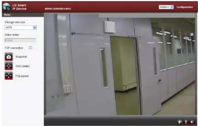
LG Smart Web Viewer Overview
text_image
LG Smart IP Device admin (Administrator) Easter-2 Configuration Menu Change view size AUTO3 Video codec 1264 TOP connection Snapshot OSS control PTZ control| Item Description | |
| Change view sizeAUTO | Select the video image size from the drop-down list.The initial view size is set to AUTO. |
| Video codecH.264 | Displays the current video codec of the selected video stream (Master or Slave). |
| TCP connection | Check this option as the network connection type (TCP or UDP). If you check it, the client connects to the server using TCP connection. |
 Snapshot Snapshot | Click to save the current image in JPEG format on your computer.1. Click the [Snapshot] button and then the Snapshot window is displayed.2. Click the [Save] button in the Snapshot window.3. Enter the file name (JPEG format) and select the folder to save it.4. Click the [Save] button to confirm it.5. Click the [Close] button in the Snapshot window to close it. |
 OSD control OSD control | Displays the Camera OSD control window. Use these buttons to setup the Camera. This button does not appear on the screen if the login is other than the administrator. |
 PTZ control PTZ control | Displays the PTZ control window. Use these buttons to control the PTZ unit. This button is not displayed with normal or anonymous user. (The function depends on the model.) |
 | Select the video stream. From the Live view drop-down list, select the desired video image source between [Master-0] and [Slave-0].Note:Master and Slave are output video streams. You can set the stream configurations independently for either Master or Slave stream. This would facilitate the user to set the live view at his comfort. |
| Configuration | Provides all the necessary tools for setting up the device to your requirements. The user will need administrator level to do this.Note:If you want to exit the Configuration menu, select one of the video stream in the Live view drop-down list. |
| Displays the current surveillance live screen. You can monitor the camera image on the live view window of the LG Smart Web Viewer. | |
| Click this button to connect or disconnect the audio communication between the LG IP device and the connected PC.(Color icon: On, Gray scale icon: Off.) | |
| Click this button to switch the microphone off and on for the computer.(Color icon: On, Gray scale icon: Off.) | |
| Click this button to switch the sound off and on, for the speaker of the computer.(Color icon: On, Gray scale icon: Off.) |
Configuration menu overview
The following table shows the list of menu items.
The configuration images are different from each model.
| Main Menu Sub | Menu Note | |
| System | Version | |
| Date & Time | ||
| Maintenance | ||
| Log & Report | ||
| Language | ||
| Audio & Video | Camera | |
| Stream | ||
| Audio Option | ||
| PTZ protocol Option | ||
| Preset Option | ||
| Motion detect | ||
| Auto Tracking Option | ||
| Network | Basic | |
| RTP stream | ||
| TCP/IP | ||
| DDNS | ||
| IP filtering | ||
| SNMP | ||
| User Basic | ||
| Event | Event schedule | |
| Event server | ||
| Sensor & Relay Option | ||
| Fan Option | ||
Configuring the LG Network Camera Device
The features and options of the LG IP camera are configured through the Configuration menu.
Only administrator-level users have permission to access the Configuration menu.
Accessing the Configuration menu
Click the [Configuration] button to display the LG Smart Web Viewer configuration window.
Warning
The Configuration setup should be made by qualified service personnel or system installers.
System settings
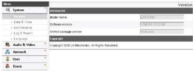
Version
Displays the current version of Firmware, Hardware, Software and Web Client.
text_image
Menu System • Version • Date & Time • Maintenance • Log & Report • Language Audio & Video Network User Event Version list Model Name:LHP3700T Software version:1208.0.0.1212150 Unitos package version:1526.88X Copyright Copyright 2009 LO Eletronics. All Rights Reserved.Date & Time
text_image
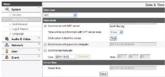
Menu System Version Maintenance Log & Report Language Audio & Video Network User Event Date & Time Time zone qmt Time mode Synchronize with NTP server pool.ntp.org Time will be synchronized with NTP server every 1 hour Click button to test this server Test Synchronize with personal computer 2011-11-03:00:50:04 Synchronize manually Date 2011-11-03 Calendar Time 09 59 03 Server time Server time 2011-11-03:00:50:03 SaveTime zone
Set the time difference from GMT in the area where the IP device is installed. Select the time zone in the area where the IP device is installed from the drop down list.
Time mode
Synchronize with NTP Server: Select if you want to synchronize the IP device's date and time with those of the time server called NTP (Network Time Protocol). Specify the NTP server's name. Click the [Test] button for connection test to the server.
Synchronize with personal computer: Select if you want to synchronize the IP device's date and time with your computer.
Synchronize manually: Select if you want to set the IP device's date and time manually. Select the year, month and date by clicking the calendar button. Set hour, minutes and seconds in the edit boxes.
Notes:
- When system reboot after time setting, time of system could be delayed. If you set the time correctly, set the [Synchronize with NTP server] option.
• Refer to NTP configuration as operation system of the Recording Server when the Recording Server use recording function and NTP server.
Server time
Server time: Displays the current date and time of the IP device.
- Save: Click this button to confirm the settings.
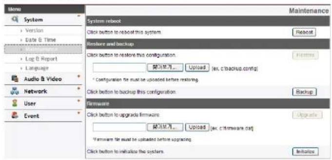
Maintenance
text_image
Menu System Version Date & Time Log & Report Language Audio & Video Network User Event System reboot Click button to reboot this system. Restore and backup Click button to restore this configuration. [+] [+] [+] [+] [+] [+] [+] [+] [+] [+] [+] [+] [+] [+] [+] [+] [+] [+] [+] [+] [+] [+] [+] [+] [+] [+] [+] [+] [+] [+] [+] [+] [+] [+] [+] [+] [+] [+] [+] [+] [+] [+] [+] [+] [+] [+] [+] [+] [+] [+] [+] (ex. c:\backup.config) * Configuration file must be uploaded before restoring. Click button to backup this configuration. Backup Firmware Click button to upgrade firmware. [+] [+] [+] [+] [+] [+] [+] [+] [+] [+] [+] [+] [+] [+] [+] [+] [+] [+] [+] [+] [+] [+] [+] [+] [+] [+] [+] [+] [+] [+] [+] [+] [+] [+] [+] [+] [+] [+] [+] [+] [+] [+] [+] [+] (ex. c:\framework.dat) [+] [+] [+] [+] [+] [+] [+] [+] [+] [+] [+] [+] [+] [+] [+] [+] [+] [+] [+] [+] [+] [+] (ex. c:\framework.dat) [+] [+] [+] [+] [+] [+] [+] [+] [+] [+] [+] [+] [+] [+] [+] [+] [+] (ex. c:\framework.dat) [+] [+] [+] [+] [+] [+] [+] [+] [+] [+] [+] (ex. c:\framework.dat) [+] [+] (ex. c:\framework.dat) [+] (ex. c:\framework.dat) [+] (ex. c:\framework.dat) [+] (ex. c:\framework.dat) [+] (ex. c:\framework.dat) [+] (ex. c:\framework.dat) [+] (ex. c:\framework.dat) [+] (ex. c:\framework.dat) [+] (ex. c:\framework.dat) [+] (ex. c:\framework.dat) [+] (ex. c:\framework.dat) [i] (i) (i) (i) (i) (i) (i) (i) (i) (i) (i) (i) (i) (i) (i) (i) (i) (i) (i) (i) (i) (i) (i) (i) (i) (i) (i) (i) (i) (i) (i) (i) (i) (i) (i) 0 Maintenance Reboot System rebound Click button to reboot this system. Restore and backup Click button to restore this configuration. [+] 0 [+] 0 [+] 0 [+] 0 [+] 0 [+] 0 [+] 0 [+] 0 [+] 0 [+] 0 [+] 0 [+] 0 [+] 0 [+] 0 [+] 0 [+] 0 [+] 0 [+] -System reboot
Click the [Reboot] button to restart the IP device. It takes some minutes for the IP device to start again.
Restore and backup
Backup: To take a backup all of the settings. If necessary, it make possible to return to a backuped configuration.
- Click the [Backup] button.
- Click the [Save] button.
- Follow the instructions on the browser to specify the folder.
- Click the [Save] button to save the settings.
Restore:
- Click the [Browse] button.
- Find and open the file in which the configuration setting data is stored.
- Click the [Restore] button and the system settings will be restored and reboot the system.
Notes:
- Backup and Restore can happen on IP device having the same version of firmware. This feature is not intended for multi-configurations or for firmware upgrades.
- [Backup] function is allowed in HTTP protocol but not in HTTPS protocol.
Firmware
> Upgrade
- Click the [Browse] button.
- Find and open the firmware file.
- Click the [Upgrade] button to update the firmware.
Note:
When you upgrade the system, it may take some minutes to be done. Do not close the browser while the upgrade is in progress. If you close the browser, it may cause a malfunction. You should wait until the confirmation window is displayed. When the upgrade is finished, the confirmation window will be displayed.
Initialize: The [Initialize] button should be used with caution. Clicking it will return all of the IP device's settings to the factory default values. (Except for the Network settings, PTZ Protocol and Preset settings. The option depends on the model.)
Log & Report
text_image
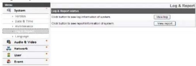
Menu System Version Date & Time Maintenance Language Language Audio & Video Network User Event Log & Report status Click button to see log information of system. Click button to see report information of system. View log View reportLog & Report status
The System log provides a summary of the status of the IP device. The unit records the data of the software activity in a file.
View Log: Click this button to display the system log information.
- Download: Click this button to see the log information of system.
View report: Click this button to display the report of the system.
- Download: Click this button to see the report information of system.
Note :
The downloaded file is a UNIX type. If you open the file in Microsoft Notepad, it will display the text as if the file contained no line breaks at all.
Language
text_image
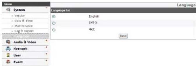
Menu System • Version • Data & Time • Maintenance • Log & Report Language Set ○ English ○ Korean ○ 中文 Save Audio & Video Network User EventLanguage list
Select a language for the LG Smart Web Viewer configuration menu and information display.
- Save: Click this button to confirm the settings.
Audio & Video settings
Camera
text_image
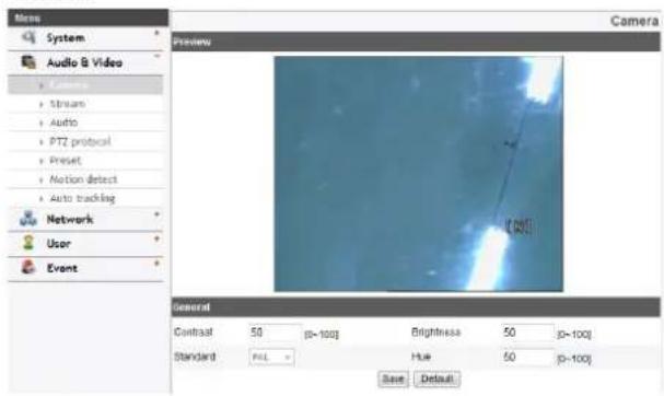
System Audio & Video • Camera • Stream • Audio • PTZ protocol • Preset • Motion detect • Auto tracking Network User Event Preview Camera General Contrast 50 (p=100) Brightness 50 (p=100) Standard PALL Hue 50 (p=100) Save DefaultPreview
You can preview the camera image on the preview window.
General
Contrast: Edit the contrast value from 0 to 100. Selecting 100 provides the image with the highest contrast.
Brightness: Edit the brightness of the camera. It is brighter when a large value is selected and it is darker when a small value is selected.Standard: Displays the video standard of the camera.
Hue: Edit the video Hue of the camera from 0 to 100.
• Save: Click this button to confirm the settings.
- Default: Click this button to restore the IP device back to original factory settings.
Stream
text_image
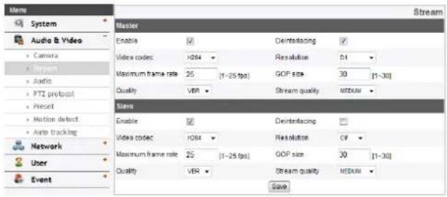
System Audio & Video Camera Ptters Audio PTZ protocol Preset Motion defect Auto tracking Network User Event Master Enable ✓ Deinterfacing ✓ Video codec HD84 Resolution 51 Maximum frame rate 25 (1-25 fps) GOP size 30 [1-30] Quality VBR Stream quality NEDUM Stream Enable ✓ Deinterfacing ✓ Video codec HD84 Resolution CF Maximum frame rate 25 (1-25 fps) GOP size 30 [1-30] Quality VBR Stream quality NEDUM SaveMaster/Slave
Enable: Click to activate the stream function.
Deinterlacing: Click to activate the deinterlacing function.
Video codec: Select the video mode (Codec) from the drop down list. The viewer can choose between MJPEG and H.264.
Resolution: Select the output image size of the camera.
Maximum frame rate: Set the frame rate of the image.GOP size: It means "Group of Pictures". The higher the GOP, the better is the video quality of the camera. Edit the value of GOP from 1 to 30. This setting is valid for H.264 video format only.
Quality: Select the Quality.
- VBR: The bit rate may vary depending on the complexity of the video to meet the selected quality.
- CBR: The video quality may vary in order to preserve a constant bit rate.
Stream quality: If the [Quality] option set to VBR, this option is displayed. Select the stream quality from the drop down box, the camera supports five types. (Highest, High, Medium, Low and Lowest)
Bit rate: If the [Quality] option set to CBR, this option is displayed. Edit the bit rate value from 256 kbps to 10 240 kbps.
Note:
If the 'Bit rate' is configured too low with high resolution, the actual frame rate will decrease because of narrow bandwidth. So you need to set or change the 'Bit rate' to high value.
- Save: Click this button to confirm the settings.
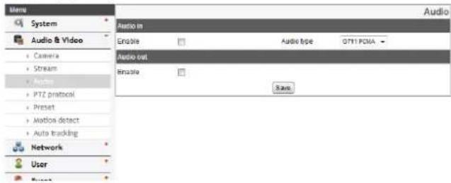
Audio (Option)
text_image
Audio System Audio & Video Camera Stream Audio PTZ protocol Preset Motion detect Auto tracking Network User Audio in Enable Audio type G711 PGMA - Audio out Enable SaveAudio In
Enable: Click the check box if you want to send the audio from the microphone input connector.
Note:
The Clients connected to the IP device remain unaffected with additional changes made in the setting.
Audio type: Select the codec when you send the audio from the microphone input connector.
Audio Out
Enable: Click the check box to output the audio from the speaker.
• Save: Click this button to confirm the settings.
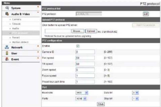
PTZ protocol (Option)
Allows the user to configure different PTZ controls by using different PTZ protocols.
text_image
Menu System Audio & Video Camera Stream Audio PTZ protocol Preset Motion detect Network User Event PTZ protocol list PTZ protocol MULTIJA Edit Upload PTZ protocol Click button to upload PTZ driver: Browse Upload Net. C:\protocol.pjt\ Protocat be must be uploaded before upgrading. PTZ configuration Enable Camera ID 0 [0-265] Pan speed 63 [0-127] Tilt speed 69 [0-127] Zoom speed 0 [0-3] Focus speed 1 [1-3] Propetour park time 1 [1-100] Port Read rate 8400 Data bit 8 Parity 90% Stop bit 1 SavePTZ protocol list
PTZ protocol: Displays the selected PTZ protocol.
Edit: Click to display the PTZ protocol window. Select the PTZ protocol and then click the [Save] button. If you want to delete the protocol, click the [Remove] button.
Upload PTZ protocol
Follow the instructions below to upload PTZ protocol.
- Click the [Browse] button, find and open the file and then click [Upload] button.
- Click the [Add PTZ protocol] button and then the PTZ protocol will be added.
PTZ configuration
Enable: Click to use the PTZ protocol.
Camera ID: Enter the PTZ device ID. Make the same ID as the PTZ Device.
Pan speed: Enter the panning speed of the PTZ device in the edit box. Default value for the LG Multix Protocol is 60 and ranges from 0 to 127.
Tilt speed: Enter the tilting speed of the PTZ device in the edit box. Default value for the LG Multix Protocol is 60 and ranges from 0 to 127.
Zoom speed: Enter the zoom speed of the PTZ device to view the object close or at a distance. Default value for the LG Multix protocol is 1 and ranges from 0 to 3.
Focus speed: Enter the focus speed of the PTZ device to focus an object clearly near or far. Default value for the LG Multix protocol is 1 and ranges from 1 to 3.
Preset tour park time: Enter the parking time.
Port
Baud rate: Select the desired speed of communication between the IP device and the PTZ Device. Confirm selected parameter to the baud rate of the IP device.
Data bit: Set the number of the data bits for RS-422/RS-485 communication.Parity: Select the desired parameter. The parity bit, added to the data, to perform parity check.
Stop bit: Enter the desired parameter. The stop bit, added to the last of data, in asynchronous communication.
• Save: Click this button to confirm the settings.
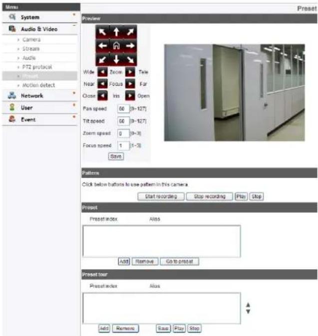
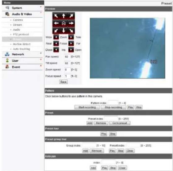
Preset (Option)
text_image
Menu System Audio & Video Camera Stream Audie PT2 protocol Motion Motion detect Network User Event Preview Wide Zoom Tale Near Focus Far Close Ins Open Pan speed 60 (9-127) Tilt speed 60 (9-127) Zoom speed 0 (9-3) Focus speed 1 (1-3) Save Patterns Click below buttons to use pattern in this camera. Start recording Stop recording Play Stop Preset Preset index Alias Add Remove Go to pre-cut Preset tour Preset index Alias Add Remove Save Play StopPreview
You can see the settings screen from the preview window.
- Move the camera to the point you want by using the arrow buttons.
- Adjust the zoom, focus or iris options.
-
Set the Pan, Tilt, Zoom or Focus speed options.
-
Click the [Save] button to confirm the settings.
Pattern
You can activate the camera in a repeating pattern. The pattern is programmed by recording your manual pan, tilt, and zoom operations. The camera stores the movements you performed in memory.
To record the pattern
- Click the [Start recording] button to start the pattern recording.
- Move the camera through the desired movement.
- Click the [Stop recording] button to stop the pattern recording.
Note:
The available total time of pattern is different depending on the connected PTZ device and operation.
To play the pattern
- Click the [Play] button to play the programmed pattern.
- Click the [Stop] button to stop playing.
Preset
Displays the registered preset position.
- Add: Click to add a preset position.
- Click the [Add] button.
- Select the preset index number.
- Enter the preset alias.
- Click the [Save] button.
- Repeat the steps 1 to 4 to add other positions.
Note:
If you set the HOME position, check the [Set home position] option.
- Remove: Click to delete the preset position.
- Select the preset from the list.
- Click the [Remove] button. The preset will be deleted.
- Go to preset: Move to the preset position.
- Select the preset from the list.
- Click the [Go to preset]. The camera will be moved to the selected preset.
Preset tour
A preset tour is composed of a group of preset positions that the operator can link together in a sequence.
To tour the preset positions
1. Choose the preset in the [Preset].
2. Click the [Add] button in the [Preset tour].
3. Repeat the steps 1 to 2 to add another preset.
4. Click the [Save] button to confirm the preset tour.
5. Click the [Play] button to start the preset tour.
6. Click the [Stop] button to stop the preset tour.
Note:
If you control the PTZ or OSD, the preset tour will be stopped.
Remove: Click this button to delete the selected preset in the [Preset tour].
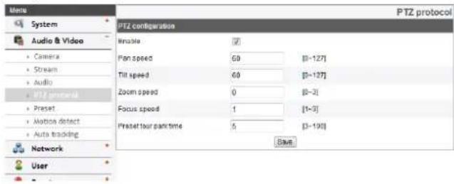
PTZ protocol (LW9228/LW9226/LW9228I/LW9226I/LNP3700T/LNP2800/LNP2800I models only)
Allows the user to configure different PTZ controls by using different PTZ protocols.
text_image
PTZ configuration Enable Pan speed 60 [0-127] Tilt speed 60 [0-127] Zoom speed 0 [0-3] Focus speed 1 [1-3] Preset tour park time 5 [3-190] Save Audio & Video Camera Stream Audio PTZ protocol Preset Motion detect Auto tracking Network User PTZ protocolPTZ configuration
Enable: Click to use the PTZ protocol.
Pan speed: Enter the panning speed of the PTZ device in the edit box. Default value for the LG Multix Protocol is 60 and ranges from 0 to 127.
Tilt speed: Enter the tilting speed of the PTZ device in the edit box. Default value for the LG Multix Protocol is 60 and ranges from 0 to 127.
Zoom speed: Enter the zoom speed of the PTZ device to view the object close or at a distance. Default value for the LG Multix protocol is 1 and ranges from 0 to 3.
Focus speed: Enter the focus speed of the PTZ device to focus an object clearly near or far. Default value for the LG Multix protocol is 1 and ranges from 1 to 3.
Preset tour park time: Enter the parking time.
• Save: Click this button to confirm the settings.
Preset
(LW9228/LW9226/LW9228I/LW9226I/LNP3700T/LNP2800/LNP2800I models only)
Note:
While configuring PATTERN/PRESET/GROUP TOUR/AUTO PAN, turn off Auto Tracking feature temporarily.
Preview
You can see the settings screen from the preview window.
text_image
System Audio & Video Camera Stream Audio PTZ protocol Multi-Select Auto tracking Network User Event Preview Wide Zoom Tele Near Focus Far Close Ins Open Pan speed 60 [0-127] Tilt speed 60 [0-127] Zoom speed 0 [0-3] Focus speed 1 [1-3] Save Pattern Click below buttons to use pattern in this camera. Pattern index (1 - 4) Start recording Stop recording Play Stop Preset Preset index (0 - 255) Add Remove Go to preset Preset pair Play Stop Preset group pair Group index (1 - 10) Preset index (0 - 255) Add Remove Play Stop Clear Auto pair index (1 - 8) Add Play Stop Clear- Move the camera to the point you want by using the arrow buttons.
- Adjust the zoom, focus or iris options.
- Set the Pan, Tilt, Zoom or Focus speed options.
- Click the [Save] button to confirm the settings.
Pattern
You can activate the camera in a repeating pattern. The pattern is programmed by recording your manual pan, tilt, and zoom operations. The camera stores the movements you performed in memory. LNP3700T/LNP2800/LNP2800I series are supported pattern recording up to 4. (LW9226/LW9228 series do not need to select a pattern index.)
» To record the pattern
- Enter the pattern number you wish to register.
- Click the [Start recording] button to start the pattern recording.
- Move the camera through the desired movement.
- Click the [Stop recording] button to stop the pattern recording.
Note:
The available total time of pattern differs depending on connected PTZ device and operation.
» To play the pattern
- Enter the pattern number you wish to register.
- Click the [Play] button to play the programmed pattern.
- Click the [Stop] button to stop playing.
Preset
Preset position is the function to register camera monitoring positions (preset positions) associated with position numbers. By entering the position numbers, you can move cameras to the preset positions.
» To register preset position
-
Enter the preset number you wish to register.
-
Move the camera to a point you wish.
- Click the [Add] button.
- Repeat the steps 1 to 3 to add other positions.
» To remove the preset position
- Enter the memorized preset index number.
- Click the [Remove] button. The preset will be deleted.
» Changing a picture in a preset position
- Enter the memorized preset index number.
- Click the [Go to preset] button. The camera moves to the preset position and the picture of the camera in that position appears on the monitor.
Preset tour
A preset tour is composed of a group of preset positions that the operator can link together in a sequence.
- Click the [Play] button to start the preset tour.
- Click the [Stop] button to stop the preset tour.
Note:
If you control the PTZ, the preset tour will be stopped.
Preset group tour
You can create a group using preset positions that are registered already.
» To set the group
- Enter the group number in the [Group index] option.
- Enter the preset index number in the [Preset index] option.
- Click the [Add] button.
- Repeat the steps 2 to 3 to add other preset index number.
- Repeat the steps 1 to 4 to set the other group index.
Operation and settings
» To remove the preset index from the group
- Enter the group number in the [Group index] option.
- Enter the preset index number in the [Preset index] option.
- Click the [Remove] button.
- Repeat the steps 2 to 3 to remove other preset index number.
- Repeat the stpes 1 to 4 to set the other group index.
» To tour the group
- Enter the group number in the [Group index] option.
- Click the [Play] button to start the group tour.
- Click the [Stop] button to stop the group tour.
» To delete a group
- Enter the group number in the [Group index] option.
- Click the [Clear] button. The group will be deleted.
Auto pan
You can play the camera with auto pan function.
» To set the Auto Pan position
- Enter the index number you wish to register.
- Move the camera to the desired point.
- Click the [Add] button.
- Repeat the steps 1 to 3 to add other index number. You can set the Auto pan index number up to 8.
» To play the auto pan
- Click the [Play] button to start the Auto Pan function.
- Click the [Stop] button to stop the Auto Pan function.
Note:
If you click the [CLEAR] button, all of Auto pan position will be deleted.
Motion detect
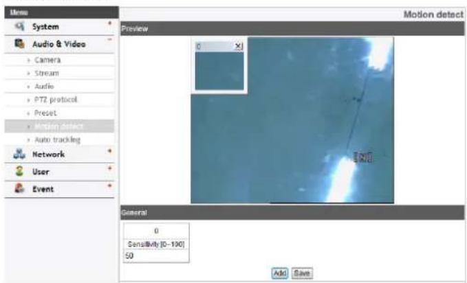
text_image
Menu System Audio & Video Camera Stream Audio PTZ protocol Preset Motion detect Auto tracking Network User Event Preview 0 General 0 Sensitivity [0-190] 50 Add Save Motion detectPreview
You can preview the motion detection window on the preview window.
General
Sensitivity: Enter the sensitivity to detect an object in motion.
Save: Click this button to confirm the settings.
How to set the motion detect window
- Click the [Add] button. The motion detect window is displayed. You can add the five windows maximum for motion detection area.
- Set the [Sensitivity] option.
- Click the edge or corner of the window box to adjust the window size for motion detection.
- Click the [Save] button to save the settings.
Note:
- You can reset the window size. Click one of the window edge or corner and drag & drop to reset the motion detection area.
- If LSW2010, LDW2010, LVS201 models, Motion Detection can be activated when at least one of channels (Master/Slave) is enabled, Video codec is set to H.264 and GOP size is more than 2.
- If not LSW2010, LDW2010, LVS201 models, Motion Detection can be activated when Master channel is enabled, Video codec is set to H.264 and GOP size is more than 2.
Auto Tracking (LW9228/LW9226/LW9228I/LW9226I/LNP3700T models only)
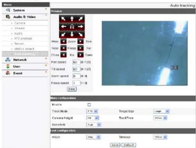
text_image
Auto tracking System Audio & Video Camera Stream Audio PTZ protocol Preset Motion detect Network User Event Preview Wide Zoom Tele Near Focus Far Close Mis Open Fan speed 60 [0-127] Tilt speed 60 [0-127] Zoom speed 0 [0-3] Focus speed 1 [1-3] Base Main configuration Enable Track Mode PTZ Target Size Large Camera HelpM SM TrackTime 305ms Sensitivity High Last configurations Action Stay Timeout 105ms Save DefaultPreview
You can see the settings screen from the preview window.
- Set the camera angle to the point you want with arrow buttons.
- Adjust the zoom, focus options.
- Set the Pan, Tilt, Zoom or Focus speed options.
- Click the [Save] button to confirm the settings.
Main configuration
Enable: Click the check box if you want to activate this function.
Track Mode: During perform the Auto Tracking, track the object using PT(Pan / Tilt) or PTZ(Pan / Tilt / Zoom).Target Size
- SMALL: Make images about 1/4 of the object using Zoom feature.
- MEDIUM: Make images about 1/2 of the object using Zoom feature.
- LARGE: Make images about 3/4 of the object using Zoom feature.
Camera Height: Set to the height of the camera.
TrackTime: Set the maximum time object tracking.
The camera moved to the initial position after tracking the amount of time set.
Sensitivity: Set the sensitivity of detection of objects.
Note:
Low sensitivity setting value can be difficult to detect of small objects or movement.
Lost configuration
Action
- Stay: When tracking is failed, the camera stays current position preparing re-tracking, does not return to the initial position.
- Return: When tracking is failed, the camera returns to the initial position preparing re-tracking.
Timeout: When tracking is failed for the first time, it tries to re-check the object during set timeout. After that, set action is performed.
- Save: Click this button to confirm the settings.
- Default: Click this button to restore the IP device back to original factory settings.
Network settings
Basic

text_image
Menu System Audio & Video Network • Base • RTP stream • TCP/IP • DDNS • IP Filtering • SNMP User Event General MAC address 90.66 91.85.78.33 Port & Encryption Web port 80 (90.1025-65635) RTSP port 564 (564.1025-95535) Network encryption HTTP FTL FTL 7 (1~250) ARP Ping Enable ARP Ping to configure IP address. SaveGeneral
MAC address: Displays the MAC address.
Port & Encryption
Web port: The default HTTP port number (80) can be changed to any port within the range 1 025 to 65 535.
RTSP port: Check RTSP port. The default port is 554. Other ports can be selected within the range 1 025 to 65 535.
Network encryption: Select the HTTP or HTTPS option for security.
Note:
The RTSP port number should not be same with the web port number.
TTL
TTL: This option indicates the Time-To-Live of multicast packets. The default setting is 7, and the allowed TTL range is from 1 to 255.
ARP Ping
Enable ARP Ping to configure IP address: Check to enable ARP ping.
- Save: Click this button to confirm the settings.
RTP stream
RTP (Real-time Transport Protocol) is an internet protocol that allows programs to manage the real-time transmission of multimedia data, via unicast or multicast.

text_image
Menu System Audio & Video Network Basic RTP stream TCP/IP DNS IP filtering SNMP User Event Master RTP unicast RTP multicast Video RTP port 8858 [1925-86534] Audio RTP port 7777 [1925-86534] Data RTP port 8666 [1925-86534] IPv4 address 239.255.214.43 [224.0.0.0 - 239.255.255.255] Slave RTP unicast RTP multicast Video RTP port 8880 [1925-86534] Audio RTP port 7777 [1925-86534] Data RTP port 8666 [1925-86534] IPv4 address 239.255.214.43 [224.0.0.0 - 239.255.255.255] SaveMaster / Slave
RTP unicast: When enabled the transmission of the data to the specified equipment happens on a network specifying a single address.
RTP multicast: When enabled it reduces the transmission load on the camera by making the computer of the same segment network receive the same transmission data. When multicast option is checked then select Video Port number, Audio Port number and Data port number.
- Video RTP port: Specify the video transmission port number used for the multicast streaming.
- Audio RTP port: Specify the audio port number used for the multicast streaming.
- Data RTP port: Specify the VA data port number used for the multicast streaming.
- IPv4 address: Set the IP address for RTP multicast.
Note:
Each stream using multicast needs its own pair of multicast IP address and port numbers to avoid address conflict.
• Save: Click this button to confirm the settings.
TCP/IP
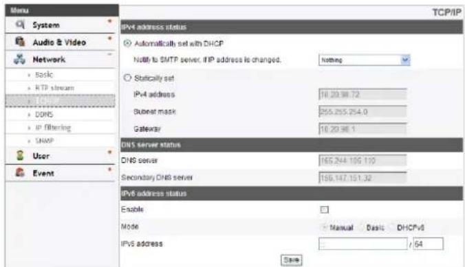
text_image
Menu System Audio & Video Network Basic RTP stream DNS IP filtering SNMP User Event TCP/IP IPv4 address status Automatically set with DHCP Notify to SMTP server, IIP address is changed. Nothing Statically set IPv4 address 10.20.98.72 Subset mask 255.255.254.0 Gateway 10.20.98.1 DNS server status DNS server 165.244.109.130 Secondary DNS server 199.147.151.32 IPv6 address status Enable Mode Manual Basic DHCPv6 IPv6 address / 64 SaveIPv4 address status
Automatically set with DHCP: Select this option when a DHCP server is installed on the network to allow IP address assignment. With this setting, the IP address is assigned automatically.
- Notify to SMTP server, if IP address is changed: If you select this option, the user get a notification mail telling about changing of IP of the IP device.
Note:
You should register the SMTP server on the Event server setting to set this function.
Statically set: Select this option when you set a fixed IP address, with this setting, specify the IP address, Subnet mask and default gateway manually.
- IPv4 address: Enter an IP address.
- Subnet mask: Enter a subnet mask address.
- Gateway: Enter the gateway address.
DNS server status
Primary DNS server: Enter the Primary domain name server that translates the hostnames into IP address.
Secondary DNS server: Enter the Secondary DNS server address that backups the Primary DNS.
• Save: Click this button to confirm the settings.
IPv6 address status
Enable: Click the check box if you want to use the IPv6 address.
Mode
- Manual: Select this option when you set a fixed IP address manually.
- Basic: Select this option to allow IPv6 address assignment based on the Mac address. With this setting, the IP address is assigned automatically.
- DHCPv6: Select this option when exist a DHCPv6 server in network. If DHCPv6 server is not existed or temporary disability, it requests assignment every 3 minutes.
IPv6 address: You can enter the IP address when you select the Manual mode. It alarms when you enter the invalid IP address.
DDNS
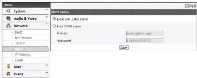
This free service is very useful when combined with the LG DDNS Server. It allows the user to connect the IP device using the URL, rather than an IP Address. This also solves the problem of having a dynamic IP address.
text_image
Menu System Audio & Video Network Basic RTP stream TCP/IP IP filtering SNMP User Event DDNS status Don't use DDNS server Use DDNS server Provider www.1pdmn.com Hostname LVW/101-35/33 SaveDDNS status
Don't use DDNS server: Disable the DDNS function.
Use DDNS server: Enable the DDNS function.
- Provider: Displays the DDNS provider.
- Hostname: Enter the hostname you want to use.
- Save: Click this button to confirm the settings.
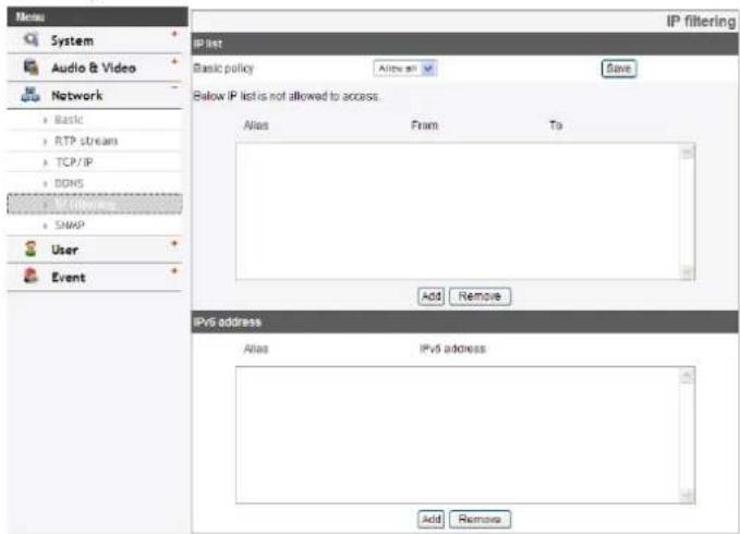
IP filtering
The access of the IP addresses in the list are allowed or denied according to the choice made in the drop-down list of the Basic policy option. The administrator can add up to 10 IP address entries to the list (a single entry can contain multiple IP addresses). The users from these IP addresses need to be specified in the user list with the appropriate access rights. The IP list is to control the access permission of clients by checking the client IP address.
text_image
Menu System Audio & Video Network Basic RTP stream TCP/IP DDNS SNAP User Event IP list Basic policy Allow all Save Below IP list is not allowed to access: Alias From To Add Remove IPv6 address Alias IPv6 address Add RemoveIP list
Basic policy: Select the basic policy type.
- Allow all: Allow all the IP address basically, but the IP addresses in the list are denied.
Operation and settings
- Deny all: Deny all the IP address basically, but the IP addresses in the list are allowed. It needs at least one IP address to activate this function.
• Save: Click this button to confirm the settings.
- Add: Click this button to add the IP address.
- Click the [Add] button.
-
Set the IP options.
-
Alias: Enter the alias.
- From: Enter the start IP address for the IP filtering.
- To: Enter the end IP address for the IP filtering.
Note:
If you want to deny or to allow a range of IP addresses, enter the start IP address to "From" and the end IP address to "To". You can also add an IP address by entering the same IP address to "From" and "To".
- Click the [Save] button.
- Repeat the steps 1 to 3 to add additional IP address.
- Remove: Click this button to delete the IP address.
- Select the alias from the list.
- Click the [Remove] button. The IP address will be deleted.
IPv6 address
- Add: Click this button to add the IP address.
- Click the [Add] button.
-
Set the IP address option.
-
Alias: Enter the alias.
-
IPv6 address: Enter the IP address for IP filtering.
-
Click the [Save] button.
- Repeat the steps 1 to 3 to add additional IPv6 address.
- Remove: Click this button to delete the IPv6 address.
- Select the alias from the list.
- Click the [Remove] button. The IPv6 address will be deleted.
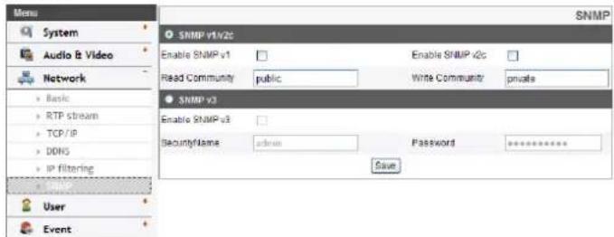
SNMP
The Simple Network Management Protocol (SNMP) is an application protocol to exchange the management information of network devices.
text_image
SNMP v1v2c Enable SNMP v1 Read Community public Enable SNMP v2c Write Community private SNMP v3 Enable SNMP v3 SecurityName admin Password ****** Save User EventSNMP v1/v2c
Enable SNMP v1/v2c: Selects when SNMP is allowed access to this device.
Read Community: Specifies the SNMP management community in which you want to read this system.
Write Community: Specifies the SNMP management community in which you want to write this system.
SNMP v3
Enable SNMP v3: Selects when SNMP v3 is allowed access to this device. It supports authentication and encryption.
SecurityName: Type the security name for the SNMP.
Password: Type the password for the SNMP.
User settings
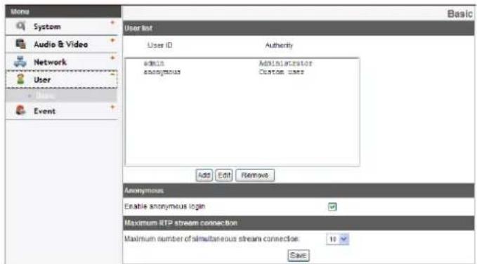
Basic
The IP device is shipped with the login rights of administrator only. If others need to access the IP device excluding the configuration a login with viewer rights need to be created. A maximum of 50 users can be created.
text_image
Menu System Audio & Video Network User Event User List User ID Authority admin Administrator anonymous Custom user Add Edit Remove Anonymous Enable anonymous login Maximum RTP stream connection Maximum number of simultaneous stream connection: 10 SaveUser list
Add the User
You can register a new user with various access rights.
- Click the [Add] button. User setting dialog is displayed.
- Enter the new User ID and Password. (Should have a minimum of 4 characters and preferably a combination of alphanumeric.)
-
To confirm the password, retype the password that you typed in the Password box.
-
Select the authority from the drop down list to provide the access rights to each user and then click the [Save] to confirm your selection.
- Administrator: Allows you to operate setup menus and to view live images.
- Power user: Use of the limited functions of the system. (The Configuration menu is not allowed.) A power user can use the Live View, OSD control and audio functions.
- Normal user: Provides the lowest level of access, Allows to view live images only.
- Custom user: The user can login and view the live stream image only when the "Enable anonymous login" option is checked to enable it.
Note:
Remember the password.
Edit the registered user
You can change the password or authority.
-
Choose the user ID and then click the [Edit] button.
-
Change the Password or Authority, then click the [Save] button to confirm your selection.
Delete the registered user
- Choose the user ID you want to delete.
- Click the [Remove] button.
Note:
The default administrator user ID 'admin' and 'anonymous' are permanent and cannot be deleted.
Anonymous
Enable anonymous login
Check the box to enable anonymous user login - allows the user access for only viewing the live stream image.
Maximum RTP stream connection
Maximum number of simultaneous stream connection:
Set this number to limit the number of simultaneous stream connections.
The connections depend on the stream configuration as shown in the following Maximum RTP stream connection by stream configuration.
| Video Codec | Resolution | Frame Rate | Quality | Maximum RTP stream |
| H.264 D1 | 30 HIGHEST Up to 5 | |||
| H.264 D1 | 30 MEDIUM Up to 10 | |||
| MJPEG D1 | 30 MEDIUM Up to 1 | |||
| MJPEG | Half D1 | 30 | MEDIUM | Up to 2 |
| MJPEG D1 | 15 MEDIUM Up to 10 |
Note:
Preview window of the IP device setting and preset setting are affected by this setting.
• Save: Click this button to confirm the settings.
Event settings
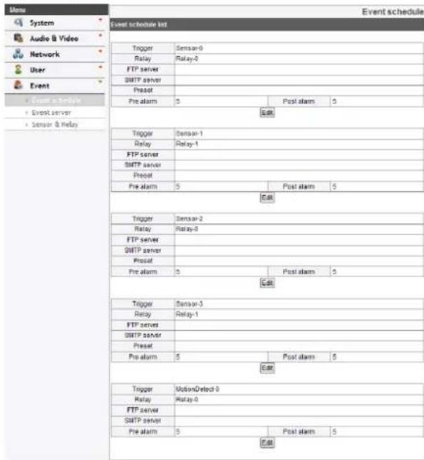
Event schedule
When an event (VA/ Motion detect/ Sensor Event) occurs, this unit records the live images and routes as configured. The event function is depending on models.
text_image
Event schedule System Audio & Video Network User Event Event & Relay Event server Sensor & Relay Trigger Relay FTP server SMTP server Precat Pre alarm 5 Post alarm 5 Edit Trigger Relay FTP server SMTP server Precat Pre alarm 5 Post alarm 5 Edit Trigger Relay FTP server SMTP server Precat Pre alarm 5 Post alarm 5 Edit Trigger Relay FTP server SMTP server Precat Pre alarm 5 Post alarm 5 Edit Trigger Relay FTP server SMTP server Precat Pre alarm 5 Post alert 5 Edit Trigger Relay FTP server SMTP server Precat Pre alarm 5 Post alarm 5 EditEvent schedule list
To edit the Event Schedule
- Select the Trigger event and click the [Edit] button. Event schedule window is displayed.
-
Set the options.
-
Trigger: Displays the selected trigger event.
• Time: Sets the weekday, Start, Finish, Pre alarm, Post alarm and Ignore interval time options.
• Action: Selects the options. This occurs when the event runs. -
FTP server/SMTP server: Uploading of images to an FTP server, or e-mail notification.
- Move camera to: Write the number of the preset, the camera would Move to this preset when the relay is activated.
- Control relay: The relay is activated or deactivated.
• Stream: Selects the stream of the connected camera.
- Programmable Alarm: When the alarm is activated, the selected stream will be set with the specified framerate and quality during the control duration.
- Click the check box if you want to activate this function.
-
Sets the options.
-
Click the [Save] button to confirm the settings.
Note:
You should register the SMTP and FTP server on the Event server setting to set this function.
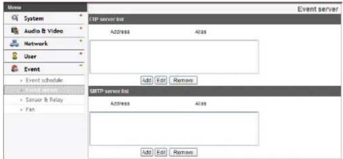
Event Server
Event Servers are used to receive the recorded video clip and/or notification messages.
text_image
Menu System Audio & Video Network User Event Event schedule Sensor & Relay Fan FTP server list Address Alias Add Edit Remove SMTP server list Address Alias Add Edit Remove Event serverFTP server list
Image files can be transferred to the FTP server within the scheduled time. Image file that has been recorded linked to an external event is sent to the FTP server periodically.
To add the FTP server
- Click the [Add] button. FTP server setting window is displayed.
-
Set the FTP server options.
-
Alias: Type the FTP Server name to upload the image files.
- Address: Enter the FTP server's IP address.
- Port: Enter the port number. The default FTP port is 21.
- User ID: Type the user name for the Folder shared in the FTP server.
- Password: Type the password for the folder shared in the FTP Server.
Operation and settings
- Folder: Type the path with the folder that is shared in the FTP server.
-
Test: Select [Test] to test the FTP server.
-
Click the [Save] button to confirm the settings.
To edit the FTP server
- Choose the FTP server in the FTP server list.
- Click the [Edit] button.
You can check or edit the FTP server options.
To delete the FTP server
- Choose the FTP server in the FTP server list.
- Click the [Remove] button. This would remove the FTP server from the list.
SMTP server list
By selecting the e-mail option, a still image of the event is captured and an e-mail with the attached image file is sent to the specified mail address.
To add the SMTP server
- Click the [Add] button. SMTP server setting window is displayed.
-
Set the SMTP server options.
-
Alias: Enter the SMTP server name.
- User ID: Enter the user ID of the SMTP server. This would be the one who owns the mail account.
- Password: Enter the password of the SMTP server.
- Address: Enter the SMTP server address.
-
Port: Enter the port number. The default port is 25.
-
Enable SSL: Check when use the SSL (Secure Socket Layer) protocol. SSL protocol is cryptographic protocols that provide secure communication on a network.
- Receiving address: Type the recipients e-mail address. You can specify only one recipient e-mail address.
- Administrator address: Type the e-mail address of the administrator.
- Subject: Enter the subject/title of the e-mail.
- Message: This message can describe the information of the acquired IP address, etc.
-
Test: Select [Test] to test the SMTP server.
-
Click the [Save] button to confirm the settings.
To edit the SMTP server
- Choose the SMTP server in the SMTP server list.
- Click the [Edit] button.
You can check or edit the SMTP server options.
To delete the SMTP server
- Choose the SMTP server in the SMTP server list.
- Click the [Remove] button.
Sensor & Relay (Option)
| Menu | Sensor & Relay | |||
| System | Sensor | |||
| Audio & Video | Enable | Alias | Type | |
| Network | ✓ | Sensor-0 | Normal open ✓ | |
| User | ||||
| Event | Relay | |||
| Event schedule | Control duration[1~86400(24hour), second] | Alias | Type | Control relay |
| Event server | 6 | Relay-0 | Normal open ✓ | Run Stop |
| Fan | Save | |||
Sensor
Enable: Marks up when you want to activate the sensor.
Alias: Displays the sensor name.
Type: Select the sensor type.
Relay
Control duration: Enter the relay time.
Alias: Displays the relay name.
Type: Select the relay type.
Control relay
- Run: Click to activate the relay.
- Stop: Click to stop the relay.
• Save: Click this button to confirm the settings.
Note:
Number of sensor and relay are depending on models.
Fan (Option)
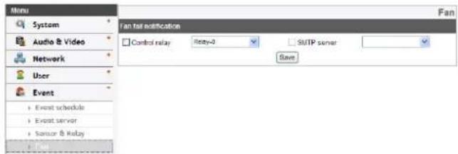
text_image
Menu System Audio & Video Network User Event Event schedule Event server Sansk & Relay Fan fail notification Control relay Rety-0 SMTP server SaveFan fail notification
Control relay: Marks up when you want to activate the selected relay.
SMTP server: Selects the SMTP server. By selecting this option an e-mail notification is sent to the user indicating a failure in the fan operation.
• Save: Click this button to confirm the settings.
OSD Menu Setup (LSW900/LSW901/LVW700/LVW701/LVW900/LVW901/LDW2010/LSW2010 series)
The following table shows the list of menu items and options.
These options are depending on models. The OSD images are different from each model.
Main Menu Sub Menu Contents
| EXPOSURE ELC/ALCorELC(LDW2010series only) | WDR/BLCorBacklight(LDW2010/LSW2010series ONLY) | The optiondepends on themodel. | |
| BRIGHTNESS 0 to 100 | |||
| AGC OFF/LOW/MIDDLE/HIGH | |||
| SHUTTER X512, ..., X2,AUTO,OFF, A.FLK,1/160,..., 1/90 000 | |||
| SENS-UP OFF | |||
| AUTO | |||
| EXIT RET/TOP/END | |||
| WHITE BAL | ATW | - | |
| AWC→PUSH | - | ||
| MANUAL COLOR TEMP INDOOR, | OUTDOOR | ||
| RED -100 to 100 | |||
| BLUE -100 to 100 | |||
| EXIT RET/TOP/END | |||
| DAY/NIGHT AUTO LEVEL LOW/ | MIDDLE/ | HIGH | |
| DWELL TIME 5, 10, | 15, 30, 60SEC | ||
| EXIT RET/TOP/END | |||
| DAY | - | ||
| NIGHT | - | ||
| 3D-DNR OFF | - | ||
| LOW | - | ||
| MIDDLE | - | ||
| HIGH | - | ||
| PRIVACY OFF | - | ||
| ON MASK | NUMBER AREA 1 to AREA 8 | ||
| DISPLAY ON/OFF | |||
| COLOR | GRAY, WHITE,BLACK | ||
| HEIGHT | 4 to 100 | ||
| WIDTH | 4 to 100 | ||
| MOVE Y | 2 to 98 | ||
| MOVE X | 2 to 98 | ||
| EXIT RET/TOP/END | |||
| SPECIAL | D-ZOOM | OFF | |
| ON | ZOOM | ||
| PAN | |||
| TILT | |||
| EXIT | |||
| D-EFFECT | OFF/V-FLIP/ MIRROR/ ROTATE | ||
| SHARPNESS | 0 to 68 | ||
| COLOR | OFF/ ON | ||
| STABILIZER | OFF/ ON | ||
| USER TITLE | OFF/ ON | ||
| LANGUAGE | The option depends on the model. | ||
| EXIT | RET/TOP/END | ||
| RESET | CAMERA REBOOT | - | |
| FACTORY RESET | - | ||
| EXIT | - | ||
| EXIT | - | - | |
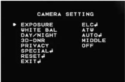
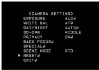
General Operation
- Click the [OSD control] button on the LG Smart Web Viewer.
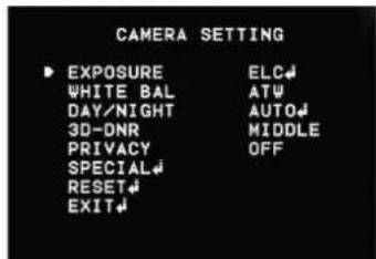
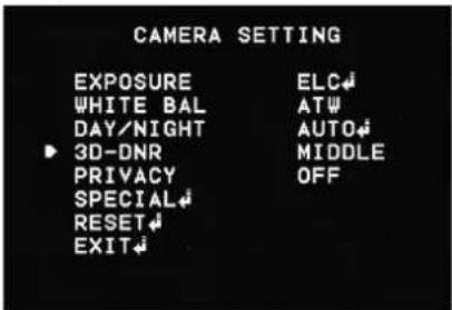
- Click button on the OSD control window. The camera setting menu appears on the live view window.
text_image
CAMERA SETTING ► EXPOSURE ELC# WHITE BAL ATW DAY/NIGHT AUTO# 3D-DNR MIDDLE PRIVACY OFF SPECIAL# RESET# EXIT#- Use ▶ o↓ button to select an option then click ↓ button. Submenu appears.
- Use ▶ c↓ button to select a submenu option.
- Use ← o→ button to select a value.
-
Select [EXIT] option then click button to exit the setup menu. In the submenu, use button to select the [EXIT] then use or button to select a mode and click button to exit the setup menu.
-
RET: Return to the previous.
- TOP: Return to the CAMERA SETTING menu screen.
- END: Exit the setup menu.
Notes:
- Button: Used to move upper direction on the menu screen.
- Button: Used to move lower direction on the menu screen.
- Button: Used to increase the value selected in the menu.
- Button: Used to decrease the value selected in the menu.
- Button: Executes selections and displays a submenu for an item with the mark.
Exposure settings
text_image
CAMERA SETTING ▶ EXPOSURE ELC# WHITE BAL ATW DAY/NIGHT AUTO# 3D-DNR MIDDLE PRIVACY OFF SPECIAL# RESET# EXIT#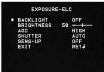
text_image
EXPOSURE-ELC BACKLIGHT OFF BRIGHTNESS 50 AGC HIGH SHUTTER AUTO SENS-UP OFF EXIT RETYou can set the exposure options using the EXPOSURE menu.
- Select [EXPOSURE] option on the [CAMERA SETTING] menu.
- Use button to select a mode.
- Press 📄 button and the EXPOSURE menu appears.
Notes:
• ELC Mode is right for outdoor scenes.
• ALC Mode is right for indoor scenes.
WDR/BLC (Option)
Use Backlight option to view the object clearly in backlight conditions.
-
Select [WDR/BLC] option on the [EXPOSURE] menu.
-
Use ← c→ button to select a mode then click ↓ button.
- WDR (Option): WDR (Wide dynamic range) feature can be very helpful to cope with very challenging lighting conditions. It is capable of capturing both of the dark part and bright part and combining the differences into a scene to generate a highly realistic image as original scene. Set the WDR limit.
ACE (Adaptive Contrast Enhancement): This function is used when you want to display dark areas of WDR brightly.
- BLC: Camera's backlight compensation feature helps alleviate issues of visibility in high contrast areas. Set the BLC limit.
- HSBLC: Use for masking brightness of the specific area to view the subject more clearly. The HSBLC mode is automatically activated only in low luminance scene.
AREA SETTING: Use ← or → button to select area then use ↑ or ↓ button to select [ON] or [OFF]. Click button to exit the area setting menu.
GRAY SCALE: Use ← or ← button to select a gray scale.
USER SCALE: Use 📋 or 📋 button to select a bright level.
MASK: Use or button to select [ON] or [OFF]. If you set the MASK to ON, the mask function is activated only when the HSBLC is activated by auto mode.
• OFF: Not in use.
BRIGHTNESS
You can increase the brightness of the darkened video. If you set the brightness to lower value, the image gets darkened. If you set the brightness to higher value, the image gets bright.
-
Select [BRIGHTNESS] option on the [EXPOSURE] menu.
-
Use ← o→ button to set the bright level.
AGC (Automatic Gain Control)
If the images are too dark, change the maximum [AGC] value to make the images brighter.
-
Select the [AGC] option on the [EXPOSURE] menu.
-
Use o button to select a mode.
SHUTTER (Shutter Speed)
Select the desired shutter speed for camera exposure. You can change the shutter speed to higher speed to capture fast-moving subjects, though the image becomes darker.
-
Select [SHUTTER] option on the [EXPOSURE] menu.
-
Use ← o→ button to set shutter speed.
SENS-UP
If pictures are not clear due to darkness, this SENS-UP operation would increase the sensitivity of picture.
-
Select [SENS-UP] option on the [EXPOSURE] menu.
-
Use ← o→ button to select a mode.
• AUTO: Adjust the sensitivity of the picture automatically.
SENS-UP LIMIT: Use ← or → button to set the SENS-UP limit.
EXIT: Select a mode and click ↕ button to exit the menu.
Note:
If you set to one of the SHUTTER options except AUTO on the [SHUTTER] menu or [AGC] to [OFF], the [SENS-UP] setting is not available and [---] mark is displayed.
White Balance settings
Select the method by which the camera shifts its output colors to compensate for the color of a light source.
text_image
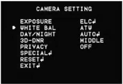
CAMERA SETTING EXPOSURE ELC↓ WHITE BAL ATW DAY/NIGHT AUTO↓ 3D-DNR MIDDLE PRIVACY OFF SPECIAL↓ RESET↓ EXIT↓-
Select the [WHITE BALANCE] option.
-
Use ← c→ button to select a mode then click ← button.
- ATW (Auto-Tracing White Balance): In this mode, white balance has better coverage than auto. Proper white balance may not be obtained under the following conditions:
When the scene contains mostly high color temperature objects, such as a blue sky or sunset.
When the scene is dim.
• AUTO: You can set the white balance options automatically.
- AWC → PUSH: If you select the AWC → PUSH mode, you will be able to set up the White Balance automatically using 📄 button.
• MANUAL: You can set the white balance options manually.
Operation and settings
COLOR TEMP: Use ← or → button to select a function.
- INDOOR: The color temperature range for the proper white balance is approximately 3 200 K.
- OUTDOOR: The color temperature range for the proper white balance is approximately 5 100 K.
RED: Set the desired red value.
BLUE: Set the desired blue value.
Day/Night settings
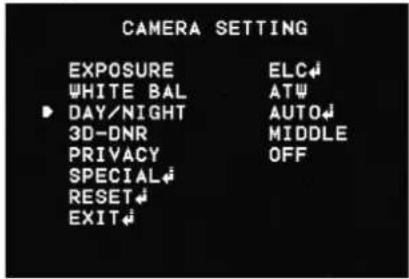
text_image
CAMERA SETTING EXPOSURE ELC↓ WHITE BAL AT↓ DAY/NIGHT AUTO↓ 3D-DNR MIDDLE PRIVACY OFF SPECIAL↓ RESET↓ EXIT↓-
Select [DAY/NIGHT] option.
-
Use ← o→ button to select a mode for DAY/NIGHT function.
• AUTO: DAY/NIGHT mode changes automatically.
Note:
If you set the AGC to [OFF] on the [EXPOSURE] menu, the AUTO mode of the DAY/NIGHT function is not available and [---] mark is displayed.
LEVEL: Use ←r button to select a level.
DWELL TIME: Use ← or → button to select a dwell time.
• DAY: Color mode enabled.
• NIGHT: Black-and-white mode enabled.
3D-DNR setting
text_image
CAMERA SETTING EXPOSURE ELC↓ WHITE BAL ATW DAY/NIGHT AUTO↓ ► 3D-DNR MIDDLE PRIVACY OFF SPECIAL↓ RESET↓ EXIT↓- Select [3D-DNR] option.
If pictures are not clear due to noise, this option would reduce the noise of picture.
- Use ← c→ button to select an option.
Notes:
- If you set the AGC to [OFF] on the [EXPOSURE] menu, the [3D-DNR] function is not available and [---] mark is displayed.
- When you use this function, the afterimage may occur.
Privacy setting
This function is aiming at the protection of personal privacy. The selected part is not displayed on the screen.
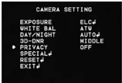
text_image
CAMERA SETTING EXPOSURE ELC↓ WHITE BAL ATW DAY/NIGHT AUTO↓ 3D-DNR MIDDLE ▶ PRIVACY OFF SPECIAL↓ RESET↓ EXIT↓- Select the [PRIVACY] option.
- Use o button to select [ON] and press the PRIVACY SETUP menu appears.
- Use ← o→ button to select a zone number (AREA1 to AREA8) on the [MASK NUMBER] option.
- Use ← c→ button to set to ON or OFF on the [DISPLAY] option. If you set to ON, the mask zone box appears on the live window.
- Use o button to select the color of the mask zone box on the [COLOR] option.
- Use ↑ o↓ button to select an option then use ← button to adjust the option.
• HEIGHT: Increase or decrease the vertical size of the mask zone box.
- WIDTH: Increase or decrease the horizontal size of the mask zone box.
• MOVE Y: Moves vertical position of the mask zone box.
• MOVE X: Moves horizontal position of the mask zone box.
Note:
The parts with the registered mask numbers from AREA1 to AREA4 have the same color. (So do the parts with the numbers from AREA5 to AREA8.) If you change the mask color, the registered mask color will be changed automatically with the same color for each of group (AREA1 to AREA4, AREA5 to AREA8).
Special menu settings
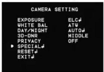
text_image
CAMERA SETTING EXPOSURE ELC# WHITE BAL AT# DAY/NIGHT AUTO# 3D-DNR MIDDLE PRIVACY OFF SPECIAL# RESET# EXIT#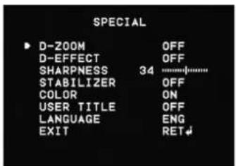
text_image
SPECIAL D-ZOOM OFF D-EFFECT OFF SHARPNESS 34 ............\... STABILIZER OFF COLOR ON USER TITLE OFF LANGUAGE ENG EXIT RETD-ZOOM
You can select the digital zoom level.
- Select [D-ZOOM] option on the [SPECIAL] menu.
- Use button to select [ON] then click button. When you set to ON, the displayed image can be shaking.
- Use ➕ button to select an option then use or ←utton to select a level.
• ZOOM: Use ← button to enlarge the screen.
• PAN: Use ← r button to move the screen. (left or right)
• TILT: Use 📋 button to move the screen. (up or down)
Operation and settings
D-EFFECT (Digital effect)
You can select the digital effect.
-
Select the [D-EFFECT] option on the [SPECIAL] menu.
-
Use ← o→ button to select a digital effect.
• V-FLIP: Flip the picture vertically.
• MIRROR: Turn on the mirror effect.
• ROTATE: Rotate the picture. (180°)
• OFF: Turn off the digital effect.
SHARPNESS
The degree to which the boundary of the two portions is clearly distinguished.
- Select the [SHARPNESS] option on the [SPECIAL] menu.
- Use o button to adjust the option. If you set the sharpness value to higher, the image outline becomes sharp. If you set to lower value, the image outline becomes dim.
STABILIZER
The image stabilizer function minimizes the appearance of shaky images caused by low-frequency vibration.
This function is useful for outdoor surveillance.
Select the [STABILIZER] option and set to ON or OFF.
Note:
If you set the [STABILIZER] to ON, the Digital zoom is set to [x1.1] automatically.
COLOR
You can switch the displayed picture to gray scale or color.
- Select the [COLOR] option on the [SPECIAL] menu.
- Use o button to change a color effect.
• ON: To display the picture with color.
• OFF: To display the picture with grayscale.
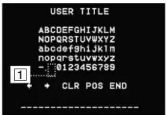
USER TITLE
You can use the camera identification to assign a number and character to the camera.
To disappear the user title, select [OFF].
-
Select the [USER TITLE] option on the [SPECIAL] screen.
-
Use ← c→ button to select [ON] then click ↓button. The USER TITLE menu appears.
text_image
USER TITLE ABCDEFGHIJKLMNOPQRSTUVWXYZ abcdefghijklmnopqrstuvwxyz - :0123456789 1 + CLR POS END- Use ▶ ↓ ↕ button to select a character or number then click ▶ button.
• CLR: Clear all entered characters and numbers.
- POS: Move the USER TITLE position on the screen using the arrow buttons.
• END: Confirm your selection or exit the setting.
• 1(Blank): Insert a space at the cursor position.
• Moves cursor to left or right.
LANGUAGE
Select the viewer language for the camera setup menu and OSD information display.
- Select the [LANGUAGE] option on the [SPECIAL] screen.
- Use ← c→ button to select the language.
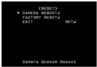
Reset setting
text_image
text_image
- Select the [RESET] option.
- Click button and the RESET menu appears.
- Use ↑ o↓ button to select option.
• CAMERA REBOOT: Reboot the camera system.
• FACTORY RESET: Clear certain settings and information and return to factory default settings.
- Click button to confirm your selection.
OSD Menu Setup (LW9226/LW9228/LW9228I/LW9226I/LNP3700T/LNP2800/LNP2800I series)
The following table shows the list of menu items and options.
LW9226/LW9228/LW9226I/LW9228I series
| 1st level 2nd level 3rd level | Contents | ||
| CAMERA SET | FOCUS | FOCUS MODE | AUTO/MANUAL/ONE PUSH/ZOOM TRIG |
| FOCUS DIST | LW9228 series:50 CM, 1.8 M, 3 M, 6 MLW9226 series:50 CM, 1 M, 3 M, 5 M | ||
| RETURN - | |||
| EXPOSURE | IRIS AUTO/MANUAL | ||
| AGC OFF/LOW/MIDDLE/HIGH | |||
| WDR/BLC OFF/WDR/BLC/HSBLC | |||
| BRIGHTNESS 0 to 100 | |||
| SHUTTER | OFF, A.FLK, 1/160, ..., 1/90000, X2, ..., X512, AUTO | ||
| SENS-UP | AUTO X2/AUTO X3/.../AUTOX128/OFF | ||
| RETURN - | |||
| CAMERA SET | WHITE BALANCE | ATW- | ||
| AUTO- | ||||
| MANUAL | COLOR TEMP | INDOOR/OUTDOOR | ||
| RED | -100 to 100 | |||
| BLUE | -100 to 100 | |||
| RETURN | - | |||
| ONE PUSH | - | |||
| DAY/NIGHT | AUTO | D/N LEVEL | LOW/MIDDLE/HIGH | |
| DWELL TIME | 5,10,15,30,60SEC | |||
| RETURN | - | |||
| DAY | - | |||
| NIGHT | - | |||
| 3D-DNR | OFF | - | ||
| LOW | - | |||
| MIDDLE - | ||||
| HIGH | - | |||
| COLOR | ON | COLOR | -20 to 20 | |
| OFF | - | |||
| SHARPNESS | 0 to 68 | - | ||
| RETURN | - | |||
| PAN/TILT SET | PRIVACY MASK | MASK NUMBER 1 | to 8 - | |
| SET MASK -- | ||||
| MASK STATE ON/OFF - | ||||
| MASK COLOR | GRAY, WHITE, BLACK | - | ||
| WIDTH 2 to 3 | 20 - | |||
| HEIGHT 3 to 4 | 40 - | |||
| RETURN - | ||||
| SPECIAL PROPORTIONAL PT ON/OFF - | ||||
| OSD SET | USER TITLE | ON/OFF |
| ZOOM MAG | ON/OFF | |
| FUNCTION | ON/OFF | |
| DOME ID | ON/OFF | |
| RETURN | - | |
| LANGUAGE | The option depends on the model. | |
| RESET | INFORMATION | - |
| INITIALIZATION | - | |
| FACTORY RESET | - | |
| RETURN | - | |
| RETURN | - | - |
LNP3700T/LNP2800/LNP2800I series
| 1st level 2nd level 3rd level | Contents | ||
| CAMERA SET | FOCUS | FOCUS MODE | AUTO/MANUAL/ONE PUSH/ZOOM TRIG |
| FOCUS DIST 1M, 3 M, 6 M | |||
| ZOOM START | LNP3700T series: x1 to x36LNP2800 series: x1 to x27 | ||
| ZOOM END | LNP3700T series: x2 to x444LNP2800 series: x2 to x336 | ||
| RETURN - | |||
| EXPOSURE | IRIS AUTO/MANUAL | ||
| AGC OFF/1 to 10 | |||
| WDR/BLC OFF/WDR/BLC/HSBLC | |||
| BRIGHTNESS 0 to 100 | |||
| SHUTTER | OFF, A.FLK, 1/160,..., 1/120 000,X2,... X512, AUTO | ||
| SENS UP AUTO X2.../AUTO X128/OFF | |||
| RETURN - | |||
| CAMERA SET | WHITE BALANCE | ATW- | ||
| AUTO- | ||||
| MANUAL | COLOR TEMP | INDOOR/OUTDOOR | ||
| RED | -100 to 100 | |||
| BLUE | -100 to 100 | |||
| RETURN | - | |||
| ONE PUSH | - | |||
| DAY/NIGHT | AUTO | D/N LEVEL | LOW/MIDDLE/HIGH | |
| DWELL TIME | 5,10,15,30,60SEC | |||
| RETURN | - | |||
| DAY | - | |||
| NIGHT | - | |||
| 3D-DNR | OFF | - | ||
| LOW | - | |||
| MIDDLE - | ||||
| HIGH | - | |||
| COLOR | ON COLOR | -50 to 50 | ||
| OFF | - | |||
| SHARPNESS | 0 to 68 | |||
| STABILIZER | OFF/ON | |||
| RETURN | - | |||
| PAN/TILT SET | PRIVACY MASK | MASK NUMBER 1 to 8 | ||
| SET MASK - | ||||
| MASK STATE ON/OFF | ||||
| MASK COLOR GRAY, WHITE, BLACK | ||||
| WIDTH 0 to 320 | ||||
| HEIGHT 0 to 240 | ||||
| RETURN - | ||||
| SPECIAL PROPORTIONAL PT ON/OFF - | ||||
| HOME POSITION | ON | SET | ||
| GO | ||||
| DWELL TIME(INFINITE, 1MIN to 100MIN) | ||||
| RETURN | ||||
| OFF - | ||||
| AUTO RETURN | ON | RETURN TIME(1 MIN to 100MIN) | ||
| OFF - | ||||
| TILT LIMIT ON/OFF - | ||||
| RETURN - | ||||
| RETURN | - | |||
| OSD SET | USER TITLE | ON/OFF |
| ZOOM MAG | ON/OFF | |
| FUNCTION | ON/OFF | |
| DOME ID | ON/OFF | |
| RETURN | - | |
| LANGUAGE The option depends on the model. | ||
| RESET | INFORMATION | - |
| INITIALIZATION | - | |
| CAMERA RESET | - | |
| FACTORY RESET | - | |
| RETURN | - | |
| RETURN - | - | |
Auto Tracking
Normal Scenario for Auto Tracking
Object detecting state
The camera starts to search a moving object. It may not start the detecting under the some conditions. See 'About Auto Tracking'.
Object tracking state
If the camera detects the object, it starts to track the object. When it uses PTZ in tracking, it'll zoom in the object if it is small. If some OSD such as USER TITLE, ZOOM MAG, FUNCTION, DOME ID, and COMPASS are enabled, they are hidden from this state.
Recovery state
When the camera is configured to PTZ mode and lost the object, it will zoom out to re-tracking the object.
Lost state
If the camera fails to re-tracking the object, it can stay its position or return to the initial position where the tracking was started. The hidden OSD is shown from this state.
While PRESET TOUR / GROUP TOUR / AUTO PAN
- When the camera is stopped at one preset position, it follows the normal scenario for the preset dwell time.
- If a moving object is detected, the camera tracks the object until the lost state.
- If a moving object is not detected for the dwell time, it goes to the next preset position. While it is moving to the next position, the Auto Tracking is stopped temporary.
- Because of the OSD, Auto Tracking might operate incorrectly while PRESET TOUR/GROUP TOUR/AUTO PAN.
About Auto Tracking
- The Auto Tracking is stopped when a user moves the camera (Pan/Tilt/Zoom) or turns on OSD Menu. It is started again whenever a user stops the control.
- The Auto Tracking is disabled temporary while the camera is moving based on some configurations: PRESET TOUR, GROUP TOUR, PATTERN TOUR, and AUTO PAN.
- When NIGHT MODE or the camera height value is configured to 2.5 M, ZOOM function will be inactivated to operate Auto Tracking correctly.
- The following conditions can cause operational errors or make Auto Tracking impossible.
- An object that is not distinguishable from background at low luminance.
- An object that has similar color with background.
- A lot of moving objects
- Unsteady camera
- Environments where a shadow is long
- Environments where there is extreme flickering or where there is light shining and light reflection on the dome
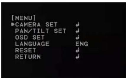
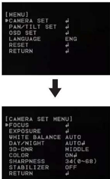
General operation
- Click the [OSD control] button on the LG Smart Web Viewer.
- Click button. The camera setting menu appears on the live view window.
text_image
[MENU] ▶CAMERA SET PAN/TILT SET OSD SET LANGUAGE ENG RESET RETURN-
Use ↑ c↓ button to select an option then click ↓ button. Submenu appears.
-
Use ▶ c↓ button to select a submenu option.
-
Use ← o button to select a value.
-
Click button to exit the setup menu. In the submenu, use button to select the [RETURN] option and click button to return to the previous.
Note:
• Button: Used to move upper direction on the menu screen.
- Button: Used to move lower direction on the menu screen.
- Button: Used to increase the value selected in the menu.
- button: Used to decrease the value selected in the menu.
- Button: Executes selections and displays a submenu for an item with the mark.
Camera menu settings
Focus setting
The camera adjusts the focus automatically by sensing the center of the picture.
text_image
[MENU] ►CAMERA SET ↓ PAN/TILT SET ↓ OSD SET ↓ LANGUAGE ENG RESET ↓ RETURN ↓ ↓ [CAMERA SET MENU] ►FOCUS ↓ EXPOSURE ↓ WHITE BALANCE AUTO DAY/NIGHT AUTO↓ 3D-DNR MIDDLE COLOR ON↓ SHARPNESS 34(0~68) STABILIZER OFF RETURN ↓Focus mode
Select [FOCUS MODE] option on the [FOCUS] menu, then select the following mode.
• AUTO: Auto-focus is activated automatically.
- MANUAL: Focus is activated automatically after the zoom movement is finished. If you want to control the focus manually, press the FOCUS (◀ r ) - buttons on the controller.
- ONE PUSH: The focus is activated manually. If the camera is received auto-focus command, the camera is activated auto-focus mode and the focus is set automatically and then the focus mode is automatically changed to manual mode.
- ZOOM TRIG: The focus is activated manually. If you change the zoom, the focus is activated automatically and then the focus mode is automatically changed to manual mode.
Focus Distance setting
Selects the minimum shooting distance for the focus. Select [FOCUS DIST] option on the [FOCUS] menu, then select a focus distance value.
Zoom Start setting (Option)
You can set the zoom start position of the camera. When the zoom function is operated, the zoom always will start at the selected zoom start position. Select [ZOOM START] option on the [FOCUS] menu, then set a zoom start position.
Zoom End setting (Option)
You can set the zoom end position of the camera. If you set the zoom end position, the zoom is operated up to the selected zoom end position. Select [ZOOM END] option on the [FOCUS] menu, then set the zoom end position.
Exposure settings
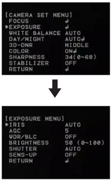
text_image
[CAMERA SET MENU] FOCUS ►EXPOSURE WHITE BALANCE AUTO DAY/NIGHT AUTO 3D-DNR MIDDLE COLOR ON SHARPNESS 34(0~68) STABILIZER OFF RETURN ↓ [EXPOSURE MENU] ►IRIS AUTO AGC 5 ψDR/BLC OFF BRIGHTNESS 50 (0~100) SHUTTER AUTO SENS-UP OFF RETURN ↓Iris setting
Select the desired lens iris value for camera exposure. Select [IRIS] option on the [EXPOSURE] menu, then select a value.
• AUTO: The lens iris is set automatically.
- MANUAL: Use ← button to select the DC Iris level. DC Iris level are set by one parameter unit.
AGC (Automatic Gain Control) setting
If the images are too dark, change the maximum [AGC] value to make the images bright.
-
Select the [AGC] option on the [EXPOSURE] menu.
-
Use button to select a value.
WDR/BLC setting
Use WDR/BLC option to set the options for BLC or WDR camera.
-
Select [WDR/BLC] option on the [EXPOSURE] menu.
-
Use button to select a mode then press .
- WDR LEVEL: WDR (Wide dynamic range) feature can be very helpful to cope with very challenging lighting conditions. It is capable of capturing both of the dark part and bright part and combining the differences into a scene to generate a highly realistic image as original scene. Set the WDR level (LOW, MIDDLE, HIGH).
- BLC LEVEL: Camera's backlight compensation feature helps alleviate issues of visibility in high contrast areas. Set the BLC level (LOW, MIDDLE, HIGH).
- HSBLC: Use for masking brightness of the specific area to view the subject more clearly.
- HSBLC LEVEL: Select the HSBLC level. (LOW, MIDDLE, HIGH).
- COLOR: Use button to select a color.
• OFF: Not used.
BRIGHTNESS setting
You can increase the brightness of the darkened video. If you set the brightness to lower value, the image gets darkened. If you set the brightness to higher value, the image gets bright.
-
Select [BRIGHTNESS] option on the [EXPOSURE] menu.
-
Use button to set the bright level.
SHUTTER (Shutter Speed) setting
Select the desired shutter speed for camera exposure. You can change the shutter speed to higher speed to capture fast-moving subjects, though the image becomes darker.
-
Select [SHUTTER] option on the [EXPOSURE] menu.
-
Use button to set shutter speed.
SENS-UP setting
If pictures are not clear due to darkness, use this function to increase the sensitivity of picture.
-
Select [SENS-UP] option on the [EXPOSURE] menu.
-
Use button to set the SENS-UP limit. To set the SENS-UP function, select the [AUTO] on the [SHUTTER].
Note:
If you set to one of the SHUTTER options except AUTO on the [SHUTTER] menu, the [SENS-UP] setting is not available and [---] mark is displayed.
White Balance setting
Select the method by which the camera shifts its output colors to compensate for the color of a light source.
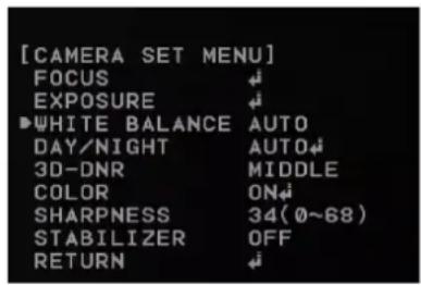
text_image
[CAMERA SET MENU] FOCUS ↓ EXPOSURE ↓ ►WHITE BALANCE AUTO DAY/NIGHT AUTO← 3D-DNR MIDDLE COLOR ON← SHARPNESS 34(0~68) STABILIZER OFF RETURN ↓- Select the [WHITE BALANCE] option on the [CAMERA SET] menu.
- Use button to select a mode then press.
- ATW (Auto-Tracing White Balance): In this mode, the color temperature range for the proper white balance is approximately from 1 800 to 10 500 K. Proper white balance may not be obtained under the following conditions:
- When the color temperature is out of the 1 800 K to 10 500 K range.
- When the scene mostly contains high color temperature objects, such as a blue sky or sunset.
- When the scene is dim.
• AUTO: In this mode, the color temperature range for the proper white balance is approximately
2 700 K to 5 400 K. Proper white balance may not be obtained under the following conditions:
- When the color temperature is out of the 2 700 K to 5 400 K range.
- When the scene mostly contains high color temperature
Operation and settings
objects, such as a blue sky or sunset.
- When the scene is dim.
- ONE PUSH: If you select the ONE PUSH mode, you will be able to set up the White Balance automatically using button.
• MANUAL: You can set the white balance options manually.
- COLOR TEMP: Use ← or → button to select a function.
INDOOR: The color temperature range for the proper white balance is approximately 3 200 K.
OUTDOOR: The color temperature range for the proper white balance is approximately 5 100 K.
- RED: Set the desired red value.
- BLUE: Set the desired blue value.
Day/Night setting
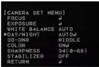
text_image
[CAMERA SET MENU] FOCUS ↓ EXPOSURE ↓ WHITE BALANCE AUTO DAY/NIGHT AUTO↓ 3D-DNR MIDDLE COLOR ON↓ SHARPNESS 34(0~68) STABILIZER OFF RETURN ↓- Select [DAY/NIGHT] option on the [CAMERA SET] menu.
- Use button to select the mode.
• AUTO: DAY/NIGHT mode changes automatically.
- D/N LEVEL: Use button to select a level.
- DWELL TIME: Use ← or → button to select a dwell time.
Note:
If you set the AGC to [OFF] or the SHUTTER is set to one of the SHUTTER options except AUTO on the [EXPOSURE] menu, the AUTO mode of the DAY/NIGHT function is not available and [---] mark is displayed.
• DAY: Color mode enabled.
• NIGHT: Black-and-white mode enabled.
3D-DNR setting
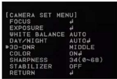
text_image
[CAMERA SET MENU] FOCUS ↓ EXPOSURE ↓ WHITE BALANCE AUTO DAY/NIGHT AUTO↓ ►3D-DNR MIDDLE COLOR ON↓ SHARPNESS 34(0~68) STABILIZER OFF RETURN ↓- Select the [3D-DNR] option. If pictures are not clear due to brightness, use this function to reduce the noise of picture.
- Use button to select an option.
Note:
- If you set the AGC to [OFF] on the [EXPOSURE] menu, the [3D-DNR] function is not available.
- When you use this function, the afterimage may occur.
Color setting
You can switch the displayed picture to grayscale or color.
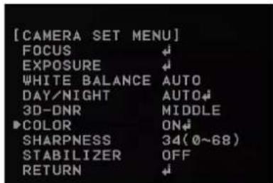
text_image
[CAMERA SET MENU] FOCUS ↓ EXPOSURE ↓ WHITE BALANCE AUTO DAY/NIGHT AUTO↓ 3D-DNR MIDDLE ▶COLOR ON↓ SHARPNESS 34(0~68) STABILIZER OFF RETURN ↓- Select the [COLOR] option on the [CAMERA SET] menu.
- Use button to change a color effect.
- ON: To display the picture with color. Select ON and press 📄 to display the submenu. You can adjust the color level using the 📄 or 📄 button.
• OFF: To display the picture with grayscale.
Sharpness setting
Sharpens the image outline.
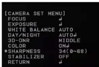
text_image
[CAMERA SET MENU] FOCUS EXPOSURE WHITE BALANCE AUTO DAY/NIGHT AUTO 3D-DNR MIDDLE COLOR ON SHARPNESS 34(0~68) STABILIZER OFF RETURN- Select the [SHARPNESS] option on the [CAMERA SET] menu.
- Use button to adjust the option. If you set the sharpness value to higher, the image outline becomes sharp. If you set to lower value, the image outline becomes dim.
Stabilizer setting (Option)
The image stabilizer function minimizes the appearance of shaky images caused by low-frequency vibration.
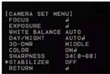
text_image
[CAMERA SET MENU] FOCUS ↓ EXPOSURE ↓ WHITE BALANCE AUTO DAY/NIGHT AUTO↓ 3D-DNR MIDDLE COLOR ON↓ SHARPNESS 34(0~68) ▶STABILIZER OFF RETURN ↓This function is useful for outdoor surveillance. Select [STABILIZER] option and set to ON or OFF.
Note:
- If you set the [STABILIZER] to ON, the Digital zoom is set to [x1.1] automatically.
• [STABILIZER] is not activated for LW9226(I) and LW9228(I) models.
PAN/TILT Settings
Privacy Mask setting
This function is aiming at the protection of personal privacy, the mask zone is not displayed on the screen. Up to 8 zones can be registered.
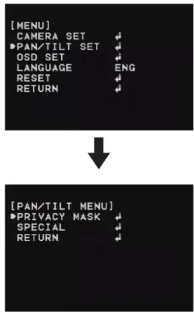
text_image
[MENU] CAMERA SET ▶PAN/TILT SET OSD SET LANGUAGE ENG RESET RETURN [PAN/TILT MENU] ▶PRIVACY MASK SPECIAL RETURN- Select the [PRIVACY MASK] option on the [PAN/TILT MENU].
- Press button to display the PRIVACY MASK MENU.
-
Use b→ion to select a zone number on the [MASK NUMBER] option.
-
Select the [SET MASK] option and press button.
- Select the mask zone using the PTZ control buttons and then press button to save it.
- Use button to set to [ON] or [OFF] on the [MASK STATE] option. If you already registered the mask zone and set to ON, the mask zone box appears on the monitor.
- Use button to select the color of the mask zone box on the [MASK COLOR] option.
- Select the [WIDTH] option and use button to adjust the horizontal size of the mask zone box.
- Select the [HEIGHT] option and use 📄 button to adjust the vertical size of the mask zone box.
- Repeat steps 3 to 9 to add additional positions.
Notes:
- The parts with the registered mask numbers from 1 to 4 have the same color. (So do the parts with the numbers from 5 to 8). If you change the mask color, the registered mask color will be changed automatically with the same color for each of group (1 to 4, 5 to 8).
- The initial PRIVACY MASK color is set to black. After setting, the PRIVACY MASK position on [SET MASK] option, it'll be changed to gray color.
Be sure, you have to press 📋 button on the [SET MASK] option to confirm the privacy mask color.
Special setting
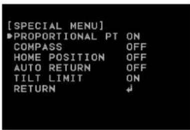
text_image
[SPECIAL MENU] ►PROPORTIONAL PT ON COMPASS OFF HOME POSITION OFF AUTO RETURN OFF TILT LIMIT ON RETURN ↓Proportional PT
This function optimizes the image by automatically adjusting the PAN/TILT (horizontal/vertical rotation) speed according to the zoom ratio.
- Select [PROPORTIONAL PT] option on the [SPECIAL] menu.
- Use □ c→ button to toggle it on and off.
• ON : Pan/tilt speed is in inverse proportion to the zoom ratio.
• OFF : The speed is constant at the fastest level regardless of the zoom ratio.
Compass
You can display the north, south, east and west information on the screen.
- Select [COMPASS] option on the [SPECIAL] menu.
- Set the [COMPASS] option to [SET] and then press button.
- Select north point using the PTZ control buttons and then press button.
- Set the [COMPASS] option to [ON].
Home position
The home position is the camera's basic position.
The camera returns to this position whenever you want.
Use the following procedure to make the home position.
- Select [HOME POSITION] option on the [SPECIAL] menu.
- Use ← c→ button to set it ON.
- Press ← button.
- Select [SET] option and then press button.
- Select the home position where you want and then press 📣 button.
- Select [DWELL TIME] option and then select the dwell time.
- Select [RETURN] option and press button to exit the setting menu.
» Go to Home position
- Select [HOME POSITION] option on the [SPECIAL] menu.
- Use ← o→ button to set it ON.
- Press button.
- Select [GO] option and then press 📋 button. The camera will move to the home position.
Note:
If you set the [HOME POSITION] to [ON], the [AUTO RETURN] option is set to [OFF] automatically and you can not use it. (LW9226(I)/LW9228(I) series only)
Auto return
This function can be used to specify automatic return to a particular mode if a certain amount of time elapses without any operation being performed.
- Select [AUTO RETURN] option on the [SPECIAL] menu.
- Use ← or button to set it [ON] and then press button.
- Select [RETURN TIME] option and then select the auto return time.
- Select [RETURN] option and press button to exit the setting menu.
Note:
If you set [AUTO RETURN] to [ON], the [HOME POSITION] option is set to [OFF] automatically and you can not use it.
(LW9226(I)/LW9228(I) series only)
Tilt limit
You can specify the tilt range. If you set this function, the camera is able to tilt from 15^ to 165^ .
- Select [TILT LIMIT] option on the [SPECIAL] menu.
- Use ← c→ button to set it [ON]. If you do not want to use this function, set it to [OFF].
OSD Settings
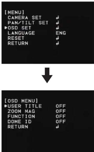
text_image
[MENU] CAMERA SET PAN/TILT SET ►OSD SET LANGUAGE ENG RESET RETURN ↓ [OSD MENU] ►USER TITLE OFF ZOOM MAG OFF FUNCTION OFF DOME ID OFF RETURNNote:
[DOME ID] is not activated for LNP3700T,LNP2800,LNP2800I models.
User title setting
You can use the camera identification to assign a number and character to the camera.
-
Select [USER TITLE] option on the [OSD] menu.
-
Use ← c→ button to set it [ON].
- Press button. The USER TITLE menu appears.
- Use ▲ ▼ ▼ ▼ button to select a character, number, symbol mark or option item.
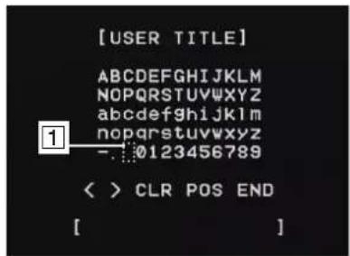
text_image
[USER TITLE] ABCDEFGHIJKLMNOPQRSTUVWXYZ abcdefghijklmnopqrstuvwxyz nopqrstuvwxyz -:0123456789 < > CLR POS END [ ]- </>: Moves cursor to left or right.
• 1 (Blank): Insert a space at the cursor position. - CLR: If you enter the wrong code, select [CLR] then press All letters will be erased at once.
- POS: Move the USER TITLE position on the screen using the or buttons.
• END: Select this option to exit the settings.
ZOOM MAG setting
Displays or removes the zoom OSD on the screen.
- Select [ZOOM MAG] option on the [OSD] menu.
- Use ← c→ button to set it [ON] or [OFF].
- Select [RETURN] option and press 📄 button to exit the setting menu.
FUNCTION setting
Displays or removes the Function OSD on the screen.
- Select [FUNCTION] option on the [OSD] menu.
- Use ← c→ button to set it [ON] or [OFF].
- Select [RETURN] option and press button to exit the setting menu.
DOME ID setting (Option)
Displays or removes the Camera ID OSD on the screen.
- Select [DOME ID] option on the [OSD] menu.
- Use ← c→ button to set it [ON] or [OFF]
- Select [RETURN] option and press button to exit the setting menu.
Note:
USER TITLE, ZOOM MAG, FUNCTION, DOME ID, and COMPASS are hidden when the camera starts tracking an object. When the tracking is stopped, those will be displayed as configured.
LANGUAGE Setting
Select a language for the setup menu and OSD display.
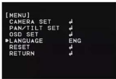
text_image
[MENU] CAMERA SET ↓ PAN/TILT SET ↓ OSD SET ↓ ►LANGUAGE ENG RESET ↓ RETURN ↓RESET Setting
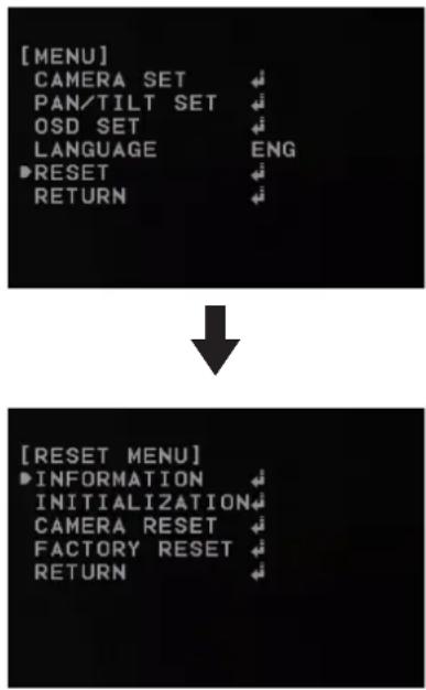
text_image
[MENU] CAMERA SET PAN/TILT SET OSD SET LANGUAGE ENG ▶RESET RETURN [RESET MENU] ▶INFORMATION INITIALIZATION CAMERA RESET FACTORY RESET RETURNNote:
[CAMERA RESET] is not activated for LW9226(I) and LW9228(I) models.
Information
You can view the current camera information such as PTZ software version, camera software version, camera ID, Protocol and Baud Rate.
- Select [INFORMATION] option on the [RESET] menu.
- Press ← button to display the current camera information.
Initialization
You can initialize the camera settings.
- Select [INITIALIZATION] option on the [RESET] menu.
- Press ← button then confirmation window is displayed.
- Select [YES] and press button.
Camera reset (Option)
- Select [CAMERA RESET] option on the [RESET] menu.
- Press [Open] or [Close] button then confirmation window is displayed.
- Select [YES] and press [Open] or [Close] button.
Factory reset
Clear certain settings and information and return to factory default settings.
- Select [FACTORY RESET] option on the [RESET] menu.
- Press button then confirmation window is displayed.
- Select [YES] and press 📋 ton. The camera will return to the factory default settings.
Reference
Troubleshooting
This section provides useful information to help you to resolve any difficulty you might have with your LG IP device. Fault symptoms, possible causes and remedial actions are provided here.
IP Setting problems
• ARP/Ping: Disconnect and reconnect the power to the network camera. The device should get the IP within 2 minutes.
- Ping your camera: Open the command prompt on your computer, type ping with the IP address of the network device. The reply obtained by this command provides explanation for the cause of the problem.
- bytes = 32 time = 2 ms indicates that the IP address is already used and cannot reuse the same. A new IP address needs to be obtained.
- Destination host unreachable: indicates that the network device and your computer do not fall in the same subnet hence needs to get a new IP address. Contact the system administrator for the required help.
- Request timed out: Indicates that the IP is free as it is not used by anyone and the network device can obtain this.
- IP Conflicts: If the LG network device is set with a static IP address and if the DHCP option is set then there may be IP's same as the network device and other network partner. Hence set the static IP address to 0.0.0.0 to resolve this conflict.
Cannot access the camera from browser:
• Reconnect the network camera with power and check the ping operation to know if the IP is used by others.
- Disable the proxy setting in the Browser if you are using a proxy server.
- Check for proper cabling and network connections, try to ping after verifying the connectivity.
- Sometimes when HTTPS is enabled, we would be checking the URL with http, in this case manually change the URL to the http/https accordingly.
• Verify the DNS and Gateway settings if the IP address is assigned statically to the network device.
Accessing camera external to the local network
- Firewall Protection: Check for the internet firewall with the system administrator, either he has to do port forwarding or modify the DMZ function on the router.
- Default router needed: Check if you need configure the router settings.
Sporadic network performance
• Network Switches or hubs used may be of the lower configuration and the load on this may not meet the required conditions of our network camera.
- Check for the RJ-45 cables that are used for the network connectivity.
• If POE is used check if the power is got by the network camera when connected to it.
Login Password lost
- Reset the camera by pressing the Reset button for more than 3 seconds to restore default settings.
• After the factory settings login using the default user name and password.
Video Streaming problems
- If the video streaming does not start on the Web browser, install the LG Web Client ActiveX program on your computer following the instructions on the Web browser.
- When Windows IE browsers are used always take care to allow pop ups, check this option before we run the web client.
- Check the quality of image by referring the video settings as described in the manual.
- Sometimes there would be intermittent or very slow video streaming, this may be because of the higher resolution and frame rate that are set for the video.
- The video streaming may appear poor at times, this may be because of the network traffic, too many devices connected to the switch or hub, enabling motion detection to each of the video streams and because of other programs running on your computer.
• If the images appear to be blurred adjust the focus of the network camera to get a clear image.
• Video images if appear white and black adjust the settings in the OSD to get back the colorful image. -
Select the Night mode if the network camera is connected at a place where surrounding light is less or dark.
-
If we obtain lower frame rate than set we need to check from the system administrator for sufficient bandwidth available or reduce the number of applications running on the client computer.
- If the client PC's are unable to access the multicast stream, check with the system administrator for the use of a valid multicast address or check if the router is supporting multicasting.
• If the images appear to have white of gray stripes on it, upgrade the Video graphics driver on the client PC to the latest version.
• Video images may be noisy if you are using the camera in a very low light environment or the bit rate/quality is set to very low values. Provide higher values for quality and support the surrounding environment with enough light.
Audio condition
The client computer that is interacting with the camera needs to have a sound card that is functional to support speaker and microphone. The sound card needs to be checked for its support for full duplex communication.
Ensure that the mute button of the client computer is not set and all the audio settings are correct.
Speaker button on the web viewer should be enabled to listen the audio from the network camera.
Ensure that the bidirectional audio button is enabled on the Web viewer and the microphone is set.
Change the input and the output gain for microphone and the speaker respectively to set correct audio level.
For all further support please contact the supplier or forums or websites.
Open source software notice
To obtain the source code under GPL, LGPL, MPL and other open source licenses, that is contained in this product, please visit http://opensource.lge.com. In addition to the source code, all referred license terms, warranty disclaimers and copyright notices are available for download. LG Electronics will also provide open source code to you on CD-ROM for a charge covering the cost of performing such distribution (such as the cost of media, shipping and handling) upon email request to opensource@lge.com. This offer is valid for three (3) years from the date on which you purchased the product.Specifications
Specifications
LSW900/LSW901/LVW700/LVW701/LVW900/LVW901/LSW2010/LDW2010 Series
| Item LSW900 LSW901 LVW700 LVW701 LVW900 LVW901 LSW2010 LDW2010 | |||||
| Image Device | 6 mm (1/3 type) Vertical Double Interline CCD | 6 mm (1/3 type) Super HAD II CCD | |||
| Lens Type | C/CS Mount Varifocal Lens (2.8 mm to 11 mm) C/CS Mount | Fixed Lens(F=3.7 mm) | |||
| Video Out 1.0 Vp-p Composite Signal (75 Ω) | |||||
| Auto Gain Control OFF/ LOW/ MIDDLE/ HIGH | |||||
| Exposure ALC/ELC ELC | |||||
| Electric Shutter 1/50 to 1/90 000 (PAL), 1/60 to 1/90 000 (NTSC) | |||||
| Day/Night | True Day and Night ( Auto/ Day / Night ) | Digital Day and Night(Auto/ Day / Night ) | |||
| Sens-Up | AUTO/OFF | ||||
| Minimum Illumination | Color | 0.1 lx (Sens-up Off ) | 0.06 lx(Sens-up Off ) | 0.3 lx(Sens-up Off ) | |
| B/W | 0.000 03 lx (Sens-up On) | 0.000 06 lx(Sens-up On) | 0.000 06 lx(Sens-up On) | ||
| White Balance | ATW / AWC / Manual | ||||
| Backlight Compensation | BLC/WDR/HSBLC/OFF | BLC/WDR | BLC/HSBLC/OFF | ||
| 3D-DNR | OFF/ Low/ Middle/ High | ||||
| Privacy Masking | 8 Zone | ||||
| Digital Zoom X8 | |||||
| DIS(Stabilizer) | ON/OFF | ||||
| Digital Effect | OFF/ V-Flip / Mirror / Rotate | ||||
| Resolution (Max) | 704 x 480 (NTSC), 704 x 576 (PAL) | ||||
| Output | RJ-45 (Network), CVBS (Monitor) | ||||
| Frame Rate (Maximum) | 30 fps/25 fps (NTSC/PAL) | ||||
| Compression H.264 (Basic Profile), MJPEG, Dual Stream | |||||||||
| Audio Full Duplex (Line level input/output) | |||||||||
| Audio Compression G.726, G.711(A-law, u-law) | |||||||||
| Sensor/Relay 1 digital input, 1 relay output | |||||||||
| VA Intruder | detection | Not Support | Support | Not Support | Support | Not Support | Support | Not Support | |
| Crossing Line | Not Support | Support | Not Support | Support | Not Support | Support | Not Support | ||
| Object Removal | Not Support | Support | Not Support | Support | Not Support | Support | Not Support | ||
| Object Counting | Not Support | Support | Not Support | Support | Not Support | Support | Not Support | ||
| Tampering | Not Support | Support | Not Support | Support | Not Support | Support | Not Support | ||
| Event Detection | Sensor In, Motion detect | ||||||||
| - | VA | - | VA | - | VA | - | - | ||
| Event Notification Relay, SMTP, FTP | |||||||||
| ID/Password | Multi level user ID/password (Admin, Power, Normal, Customer) | ||||||||
| Encryption | HTTPS (SSL,TLS) | ||||||||
| Physical Layer | 10/100 base TX Ethernet | ||||||||
| Protocol | IPv4 and IPv6 | TCP/IP, UDP, HTTP, HTTPS, RTP, RTSP, DHCP, ICMP | |||||||
| IPv4 | FTP, SMTP, NTP, ARP, SNMP v1/v2c/v3, DDNS(LG) | ||||||||
| IP support | Dynamic, Static, Private IP | ||||||||
| Users | Unicast 10 Streams / 50 user registration | ||||||||
| Operation Temperature / Humidity | -10 °C to 50 °C / 0 %RH to 80 %RH | -30 °C to 50 °C / 0 % RH to 80 % RH | -10 °C to 50 °C / 0 %RH to 80 %RH | ||||||
| Fan Operation Temp | Not Support | <15 °C (Dome inside) | Not Support | ||||||
| Power Source | PoE, AC 24 V (±20 %) (1 A or above)DC 12 V (±10 %) (2 A or above) | PoE, AC 24 V (±20 %)(1.5 A or above)DC 12 V (±10 %)(3 A or above) | PoE, DC 12 V (±10 %)(1 A or above) | ||||||
| Power Consumption | About 9 W About 10 W | About 10 W(without heater),13 W (with heater) | About 4.2 W (DC),About 5.7 W (PoE) | ||||||
| Other RS-485 Support Not | Support Not Support Not Support | ||||||||
| Dimension | 69 mm x 54 mm x128.5 mm (W x H x D) | ∅156 mm x 155 mm (Φ xH) | (W) 67.4 mm x(H) 135.4 mm x(D) 61.5 mm | ∅122 mm x102 mm (Φ xH) | |||||
| Weight 0.5 kg 0.86 kg 1.4 kg | 370 g 415 g | ||||||||
LVS201/LVS301/LVS311 Series
| Item LVS201 LVS301 LVS311 | ||||
| Resolution (Maximum) 704 x 480 (NTSC), 704 x 576 (PAL) | ||||
| Output RJ-45(Network), RJ-45 (Network), CVBS (Monitor) | ||||
| Frame Rate (Maximum) 30 fps/25 fps(NTSC/PAL) | ||||
| Compression H.264 (Basic Profile), MJPEG, Dual Stream | ||||
| Audio | Not Support | Full Duplex(Line level input/output) - Audio Input 1Ch, Audio Output 1Ch | ||
| Audio Compression Not Support G.726, G.711 (A-law, u-law) | ||||
| Sensor/Relay Not Support 1 digital input, 1 relay output | ||||
| VA Intruder | detection | Not Support Not Support Support | ||
| Crossing Line | Not Support Not Support Support | |||
| Object Removal | Not Support Not Support Support | |||
| Object Counting | Not Support Not Support Support | |||
| Tampering | Not Support Not Support Support | |||
| Event Detection | Motion detection | Sensor In, Motion Detect | Sensor In, Motion Detect, VA | |
| Event Notification | SMTP, FTP | Relay, SMTP, FTP | ||
| ID/Password | Multi level user ID/password (Admin, Power, Normal, Customer) | |||
| Encryption | HTTPS (SSL) | HTTPS (SSL,TLS) | ||
| Physical Layer 10/100 base | TX Ethernet | |||
| Protocol | IPv4 and IPv6 | TCP/IP, UDP, HTTP, HTTPS, RTP, RTSP, DHCP, ICMP | ||
| IPv4 | FTP, SMTP, NTP, ARP, SNMP v1/v2c/v3, DDNS(LG) | |||
| IP support Dynamic, Static, | Private IP | |
| Users Unicast 10 Streams / Humidity | 50 user registration | |
| Operation Temperature / Humidity | -10 °C to 50 °C / 0 % RH to 80 % RH | |
| Power Source PoE, DC 12 V | (±20 %) (1 A or above) PoE, AC 24 V (±20 %) (1 A or above), DC 12 V (±10 %) (2 A or above) | |
| Power Consumption About | 3 W About 7 W | |
| Other RS-485 Support RS-485 / RS-422 Support | ||
| Dimention (W x H x D) 100 | mm x 41 mm x 91 mm 170.4 mm x 56.2 mm x130.2 mm | |
| Weight 204 g 0.73 kg | ||
LW9226/LW9226I/LW9228/LW9228I Series
| Item LW9226 LW9226I LW9228 LW9228I | |||||
| Camera Image | Sensor 4.5 mm (1/4 type) EX-view HAD CCD | ||||
| Lens | x27 Zoom(F1.5 (Wide End), F3.8 (Tele End))(f = 3.25 mm to 88 mm) | x37 Zoom(F1.5(Wide End), F4.1(Tele End))(f = 3.5 mm to 129 mm) | |||
| Resolution Up to 704 x | 480, 704 x 576 (N/P) | ||||
| Minimum Illumination | Color Mode: 0.003 (0.6) lx (Sens-up OFF)B/W Mode: 0.000 1 (0.1) lx (Sens-up OFF) | ||||
| True Day/Night Support | |||||
| WDR Support | |||||
| Image Enhancement | Backlight Compensation, Exposure Control, Sens Up Control, AGC, White Balance, Privacy Masking, EIS, Digital Zoom | ||||
| PTZ Optical Zoom x27 x37 | |||
| Panning Range & Speed | 0° to 360°, Maximum 400°/Second | ||
| Tilting Range & Speed | 0° to 180°, Maximum 400°/Second | ||
| Auto Panning Maximum 8 points | |||
| Preset 128 | |||
| Group Touring Maximum 9 Groups | |||
| Pattern 1 EA | |||
| Auto Tracking Support | |||
| Video/Audio | Video Compression H.264, MJPEG | ||
| Frame Rate 30 fps @ D1 + 30 fps @ CIF (NTSC), 25 fps @ D1 + 25 fps @ CIF (PAL) | |||
| Multi-Streaming Dual Streaming | |||
| Audio Compression G.726, G.711 | |||
| 2-way Audio Support | |||
| Event Motion | Detection Support | ||
| Event Notification | Relay Out, Email, FTP | ||
| Pre Event Buffering | Support | ||
| Video Analytics Embedded | Not Support | ||
| Interface Video In/Out 1 BNC Out | |||||
| Audio In/Out 1/1 | |||||
| Alarm In/Out 4/2 | |||||
| Network Ethernet 10/100 Ethernet | |||||
| Security Password Protection, HTTPS (SSL, TLS) | |||||
| Protocol | IPv4 and IPv6 | TCP/IP, UDP, HTTP, HTTPS, RTP, RTSP, DHCP, ICMP | |||
| IPv4 FTP, SMTP, NTP, ARP, SNMP v1/v2c/v3, DDNS(LG) | |||||
| Remote S/W LG Ipsolute VMS or Web Client | |||||
| Connections Up to 10 | |||||
| Misc. | Protection | IP66, Vandal Proof | - | IP66, Vandal Proof | - |
| Power Source | AC 24 V | ||||
| Power Consumption | 25 W | 19 W | 25 W | 19 W | |
| Operating Temperature | -20 °C to 50 °C | -10 °C to 50 °C | -20 °C to 50 °C | -10 °C to 50 °C | |
| Humidity: 0 % RH to 80 % RH | |||||
| Safekeeping Temperature | -30 °C to 60 °C (Humidity: 0 % RH to 90 % RH) | ||||
| Weight | 4.17 kg | 2.5 kg | 4.17 kg | 2.5 kg | |
| Dimension (Φ xH) | 234.6 mm x 269.9 mm | 205.8 mm x 247.4 mm | 234.6 mm x 269.9 mm | 205.8 mm x 247.4 mm | |
LNP3700T/LNP2800/LNP2800I Series
| Item LNP3700T LNP2800 LNP2800I | |||
| Image Sensor 4.5 mm (1/4 type) CCD | |||
| Lens x37 Zoom, F1.5(Wide End), F4.1(Tele End) | (f = 3.5 mm to 129.5 mm) | x28 Zoom, F1.5 (Wide End), F3.0 (Tele End)(f = 3.5 mm to 98 mm) | |
| Resolution Up to 704 x 480 (NTSC), 704 x 576 (PAL) | |||
| Minimum Illumination B/W 0.01 lx (Sens-up OFF), 0.000 01 lx (Sens-up ON) | |||
| ICR Day/Night Support | |||
| Image Enhancement Backlight Compensation | Exposure Control, Sens Up Control, AGC, White Balance, Privacy Masking,Digital Zoom, EIS | ||
| Optical Zoom x37 x28 | |||
| Panning Range & Speed | 0° to 360°, Maximum 500°/Second | ||
| Tilting Range & Speed | 0° to 180°, Maximum 500°/Second | ||
| Auto Panning | 2 to 8 points | ||
| Preset | 256 | ||
| Group Touring | Maximum 10 Groups | ||
| Pattern | 4 EA | ||
| Auto Tracking Support | No Support | ||
| Video Compression | H.264, MJPEG | ||
| Frame Rate | 30/25 fps @ D1 (N/P) + 30/25 fps @ CIF (N/P) | ||
| Multi-Streaming | Dual Streaming | ||
| Audio Compression | G.726, G.711 | ||
| 2-way Audio | Support | ||
| Motion Detection Support | |||
| Event Notification Relay Out, Email, FTP, Preset(on Sensor) | |||
| Pre Event Buffering Support | |||
| Video In/Out 1 BNC Out | |||
| Audio In/Out 1/1 | |||
| Alarm In/Out 4/2 | |||
| Ethernet 10/100 Ethernet | |||
| Security Password Protection, HTTPS (SSL, TLS) | |||
| Protocol | IPv4 | TCP/IP, HTTP, HTTPS, RTP, RTSP, UDP, DHCP, ICMP, FTP, SMTP, NTP, ARP, SNMPv1/v2c/v3, DDNS(LG) | |
| IPv4/v6 TCP/IP, UDP, HTTP, HTTPS, RTP, RTSP, DHCP, ICMP | |||
| Open Protocol | ONVIF 2.2 Profile S,PSIA 1.1 | ||
| Remote S/W | LVi510, Mobile application (iPhone, Android, iPad) | ||
| Connections | Up to 10 | ||
| Protection | IP66, Vandal Proof | No Support | |
| Power Source | AC 24 V | ||
| Power Consumption | Maximum 25 W | Maximum 21 W | |
| Input current 1.8 A | 1.4 A | ||
| Operating Temperature | -20 °C to 50 °C | -10 °C to 50 °C | |
| Operating Humidity | 0 % RH to 80 % RH | ||
| Weight | 4.17 kg | 2.5 kg | |
| Dimension (∅xH) 234.6 mm x 269.9 mm | 205.8 mm x 269.9 mm | ||