
LSX701P - Unspecified LG - Free user manual and instructions
Find the device manual for free LSX701P LG in PDF.


| Product Type | Color Video Camera (CCTV) |
| Model | LSX701P |
| Pick-up Device | 1/2 inch Interline EX-view HAD CCD |
| Signal System | PAL |
| Horizontal Resolution | More than 650 TV Lines |
| Lens Mount | C/CS Mount |
| Minimum Illumination (Day) | 0.0001 Lux (Sens-up Auto, F1.2) |
| Minimum Illumination (Night) | 0.00001 Lux (Sens-up Auto, F1.2) |
| Video Output | 1Vp-p Composite (75 ohm) |
| Power Source | DC12V / AC24V (Auto Switch) |
| Power Consumption | 4.4 W |
| Synchronization System | Internal / Line Lock |
| S/N Ratio | More than 52 dB (AGC Off, F1.2) |
| Operating Temperature | -10°C to 50°C (Humidity: 0%RH~80%RH) |
| Storage Temperature | -20°C to 60°C (Humidity: 0%RH~85%RH) |
| Weight | 420 g |
| Dimensions (H x V x D) | 67.4 x 61.5 x 134 mm |
| Key Features | Day & Night (Filter change), Auto Iris Control (DC/VIDEO/ELC), AGC, White Balance (ATW/Manual), Motion Detection, Privacy Masking, 3D-DNR, Digital Zoom, Digital Effects, Stabilizer, RS-232C TTL/RS-485 Communication |
Frequently Asked Questions - LSX701P LG
User questions about LSX701P LG
0 question about this device. Answer the ones you know or ask your own.
Ask a new question about this device
Download the instructions for your Unspecified in PDF format for free! Find your manual LSX701P - LG and take your electronic device back in hand. On this page are published all the documents necessary for the use of your device. LSX701P by LG.
USER MANUAL LSX701P LG
natural_image
Exterior view of a silver LG phone with lens and control panel (no visible text or symbols)CE

Color Video Camera User Manual
Model: LSX701
Before installing, operating or adjusting this product, please read this instruction booklet carefully and completely.

CAUTION
RISK OF ELECTRIC SHOCK DO NOT OPEN

CAUTION: TO REDUCE THE RISK OF ELECTRIC SHOCK
DO NOT REMOVE COVER (OR BACK)
NO USER-SERVICEABLE PARTS INSIDE
REFER SERVICING TO QUALIFIED SERVICE PERSONNEL.

This lightning flash with arrowhead symbol within an equilateral triangle is intended to alert the user to the presence of uninsulated dangerous voltage within the product's enclosure that may be of sufficient magnitude to constitute a risk of electric shock to persons.

The exclamation point within an equilateral triangle is intended to alert the user to the presence of important operating and maintenance (servicing) instructions in the literature accompanying the product.
FCC WARNING: This equipment may generate or use radio frequency energy. Changes or modifications to this equipment may cause harmful interference unless the modifications are expressly approved in the instruction manual. The user could lose the authority to operate this equipment if an unauthorized change or modification is made.
REGULATORY INFORMATION: FCC Part 15
This equipment has been tested and found to comply with the limits for a Class A digital device, pursuant to Part 15 of the FCC Rules. These limits are designed to provide reasonable protection against harmful interference when the equipment is operated in a commercial environment.
This equipment generates, uses, and can radiate radio frequency energy and, if not installed and used in accordance with the instruction manual, may cause harmful interference to radio communications.
Operation of this equipment in a residential area is likely to cause harmful interference in which case the user will be required to correct the interference at his own expense.
- A suitable conduit entries, knock-outs or glands shall be provided in the cable entries of this product in the end user.
- Caution: Danger of explosion if battery is incorrectly replaced. Replaced only with the same or equivalent type recommended by the manufacturer. Dispose of used batteries according to the manufacturer's instructions.
- Holes in metal, through which insulated wires pass, shall have smooth well rounded surfaces or shall be provided with brushings.
This Class A digital apparatus complies with Canadian ICES-003.
Warning: Do not install this equipment in a confined space such as a bookcase or similar unit.
Warning: Wiring methods shall be in accordance with the National Electric Code, ANSI/NFPA 70.
Warning: This is a class A product. In a domestic environment this product may cause radio interference in which case the user may be required to take adequate measures.
Warning: To reduce a risk of fire or electric shock, do not expose this product to rain or moisture.
Caution: This installation should be made by a qualified service person and should conform to all local codes.
Caution: To avoid electrical shock, do not open the cabinet. Refer servicing to qualified personnel only.
Caution: The apparatus shall not be exposed to water (dripping or splashing) and no objects filled with liquids, such as vases, shall be placed on the apparatus.
To disconnect power from mains, pull out the mains cord plug. When installing the product, ensure that the plug is easily accessible.
Disposal of your old appliance
- When this crossed-out wheeled bin symbol is attached to a product it means the product is covered by the European Directive 2002/96/EC.
- All electrical and electronic products should be disposed of separately from the municipal waste stream via designated collection facilities appointed by the government or the local authorities.
- The correct disposal of your old appliance will help prevent potential negative consequences for the environment and human health.
- For more detailed information about disposal of your old appliance, please contact your city office, waste disposal service or the shop where you purchased the product.

This product is manufactured to comply with EMC Directive 2004/108/EC and Low Voltage Directive 2006/95/EC.
European representative :
LG Electronics Service Europe B.V.
Veluwezoom 15, 1327 AE Almere,
The Netherlands (Tel: +31-036-547-8940)
Important Safety Instructions
- Read these instructions.
- Keep these instructions.
- Heed all warnings.
- Follow all instructions.
- Do not use this apparatus near water.
- Clean only with dry cloth.
- Do not block any ventilation openings. Install in accordance with the manufacturer's instructions.
- Do not install near any heat sources such as radiators, heat registers, stoves, or other apparatus (including amplifiers) that produce heat.
- Do not defeat the safety purpose of the polarized or grounding-type plug. A polarized plug has two blades with one wider than the other. A grounding type plug has two blades and a third grounding prong. The wide blade or the third prong are provided for your safety. If the provided plug does not fit into your outlet, consult an electrician for replacement of the obsolete outlet.
- Protect the power cord from being walked on or pinched particularly at plugs, convenience receptacles,
and the point where they exit from the apparatus.
-
Only use attachments/accessories specified by the manufacturer.
-
Use only with the cart, stand, tripod, bracket, or table specified by the manufacturer, or sold with the apparatus. When a cart is used, use caution when moving the cart/apparatus combination to avoid injury from tip-over.

-
Unplug this apparatus during lightning storms or when unused for long periods of time.
-
Refer all servicing to qualified service personnel. Servicing is required when the apparatus has been damaged in any way, such as power-supply cord or plug is damaged, liquid has been spilled or objects have fallen into the apparatus, the apparatus has been exposed to rain or moisture, does not operate normally, or has been dropped.
Cautions for Safe Operation
Power Supply
This camera must always be operated a AC 24V or DC 12V Certified/Listed, class 2 power supply only.
Note:
Be careful of AC frequency when the camera is operated with Line lock mode.
Handling of the unit
Be careful not to spill water or other liquids on the unit. Be cautions not to get combustible or metallic material inside the body. If used with foreign matter inside, the camera is liable to fail or to get cause of fire or electric shock.
- Remove dust or dirt on the surface of the lens with a blower.
- Use a dry soft cloth to clean the body. If it is very dirty, use a cloth dampened with a small quantity of neutral detergent then wipe dry.
- Avoid the use of volatile solvents such as thinners, alcohol, benzene and insecticides.
They may damage the surface finish and/or impair the operation of the camera.
Operating and storage location
Avoid viewing a very bright object (such as light fittings) during an extended period. Avoid operating or storing the unit in the following locations.
- Extremely hot or cold places (operating temperature - 10°C \~ 50°C, however, we recommend that the unit be used within a temperature range of 0°C \~ 45°C)
• Damp or dust place - Places exposed to rain
• Places subject to strong vibration - Close to generators of powerful electromagnetic radiation such as radio or TV transmitters.
Contents
Features 8
Part Names and Functions ...... 9
Connections 11
Precautions 11
Connection Overview ....11
Connecting Display device....12
Connecting Power Source 12
Connecting RS-485/RS-232C TTL Device ....13
Connecting Alarm Device 13
Connecting Day&Night Switch 14
Mounting the Lens 15
Concerning Auto-Iris Lenses ....17
Flange-back Adjustment 18
Mounting the camera 19
Menu Operation....20
OSD Menu control buttons 20
OSD Menu Overview 21
General Operation 24
Camera Identification Settings 24
Exposure Settings 25
White Balance settings 28
Day/Night Setting 29
Motion Detection Setting 30
3D-DNR Setting 31
Privacy Setting 32
Special Menu Settings....33
Reference 39
RS-232C TTL/RS-485 Protocol (Optional) ....39
Specification 40
Features
This Color Video Camera is designed for installation in an video surveillance system.
This manual contains instructions on how to install and manage the Color Video Camera in your video surveillance system.
Should you require any technical assistance, please contact authorized service center.
• High resolution and high sensitivity with a 1/2 inch Interline EX-view HAD CCD.
C/CS Mount
• 650 TV lines of horizontal resolution
• Day & Night function (Filter change)
• Line Lock when using AC 24V
• Power Supply: Automatically switch between DC 12 V and AC 24 V
Part Names and Functions

1 Lens mount cap
The lens mount of the camera is covered using a cap to protect it. Remove the lens cap covering the lens.
2 Camera installation bracket
The bracket can be fixed at the top or bottom of the camera.
3 Flange-back adjustment lever
4 Lens iris output connector (LENS)
This 4-pin connector is used to send the Iris control signal and power supply to an auto-iris type lens.
5 Setup menu control buttons
Use these buttons to set the menu options.
6 ALC Lens Setting Switch
- DC: When you attach an Auto Iris lens requiring the DC control signal, please put this switch in the DC position.
• ELC: When you attach a manual or fixed lens, please put this switch in the ELC position.
• VIDEO: When you attach an Auto Iris lens requiring the video control signal, please put this switch in the VIDEO position.
Part Names and Functions

Supplies AC 24V or DC 12V from an external power source.
8 External Device Connectors
D&N
Connect the external switch to set the D&N function manually.
• ALARM (Alarm Output Terminal)
Connect to the alarm input of an external device.
• COM (COMMUNICATION)
Connect to an external controller of RS-232C TTL/RS-485(optional) format.
9 Power indicator
Lights when the camera is powered.
10 GND
11 Video output connector (BNC type)
Supplies analog video signal (composite) to the connected device such as a DVR or monitor.
Connections
Precautions
- Be sure to switch off the unit before installation and connection.
• A qualified service person, complying with all applicable codes, should perform all required hardware installation.
• Do not expose the power and connection cable to moisture, which may cause damage to the unit.
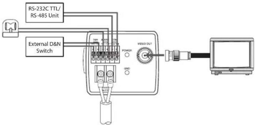
Connection Overview
flowchart
graph TD
    A["External D&N Switch"] --> B["RS-232C TTL/RS-485 Unit"]
    A --> C["USB Port"]
    C --> D["Video Output"]
    D --> E["Computer"]
Connections
Connecting Display device
The video signal connection between the camera and the monitor.

Connecting Power Source
Connect power, using the method listed below:
- Remove the insulation on the power cable as illustrated.
- Attach the terminal tips.
- Connect to the DC 12 V / AC 24 V UL Listed, Class 2 Power Supply only on the unit.

Connections
Connecting RS-485/RS-232C TTL Device
Use these ports to connect an external device of RS-232C TTL/RS-485 format.

Connecting Alarm Device
Alarm terminals are used to connect the alarm (relay) devices such as sensors, door switches, etc.
Connect the alarm (relay) device to the alarm (relay) output terminal. Alarm signal outputs at an event occurrence.

Connections
Contact Ratings
• Maximum load current is ±130mA.
• Do not connect any system or device that has over 40 Vp-p (DC 30 V) bias voltage on the contact terminal.
Note:
Use a relay unit if the voltage or current of the connected device exceeds the ratings.
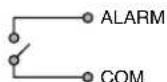
Equivalent Diagram
Connecting Day&Night Switch
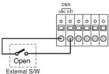
Connect the external D&N switch to the D&N terminal.
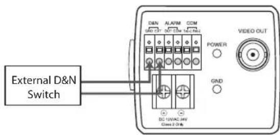
Day function
When you open the external switch, the D&N function is set to Day mode.
Connections
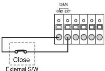
Night function
When you close the external switch, the D&N function is set to night mode.
Note:
If you use the external D&N function, you should set the DAY/NIGHT option to EXT on the setup menu.
Mounting the Lens
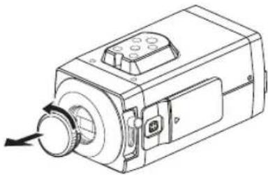
- Remove the lens mount cap from the camera.
natural_image
Technical line drawing of a mechanical device with a knob and control panel (no text or symbols)- Install the auto-iris lens.
2-1. CS mount type lens
Carefully align the lens mount with the camera
Connections
opening, then turn the lens slowly to install it.
2-2. C mount type lens
To allow for flange-back adjustment, install the C-mount adaptor (option) on the lens mount, then carefully align the lens mount with the camera opening and turn the lens slowly to install it.
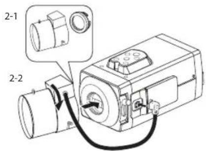
- Connect the lens plug to the lens iris output connector (LENS) on the side of the camera.
When using lenses from other makers, the plug shape may not correspond to the terminal on the camera.
In such a case, remove the original plug and using a soldering iron, connect a lens iris plug according to the diagram. (Refer to next page.)
lens iris output connector
Pin layout for the lens iris output connector.

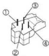
| No. DC type lenses VIDEO | type lenses |
| 1 Damping - Vcc (+9V) | |
| 2 Damping + Not used | |
| 3 Drive + Video | |
| 4 Drive - Ground |
Connections
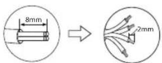
Rewire the lens iris plug
- Cut off the plug of the lens cable, cut off approximately 8mm of the insulation, and then strip approximately 2mm of the ends of the cable sheaths.
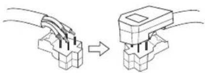
- Solder the ends of the cable wires to the ends of the pins, and then attach the cover of the lens iris plug.
natural_image
Diagram showing two connected electrical connectors with wires, one being folded and the other attached (no text or symbols)Concerning Auto-Iris Lenses
DC type auto-iris lens
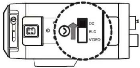
A lens without driver circuit that operates only on a DC power source. In general, this type of lens is referred to as DC type coil lens. (Set the ALC Lens Setting Switch to the DC position.)
CAUTION:
Depending on the type of lens used, the lens may not perform properly.
Connections
ELC type auto-iris lens
Use a manual or fixed iris lens (Set the ALC Lens Setting Switch to the ELC position.)

VIDEO type auto-iris lens
A lens with amplifier circuit that operates on video signal and DC power source. In general, this type of lens is referred to as EE amplifier type lens. ALC and LEVEL volume level controls are available on the lens for iris adjustments. (Set the ALC Lens Setting Switch to the VIDEO position.)
CAUTION:
Be cautions not to use Auto Iris Lens with over 35mA.

Flange-back Adjustment
The adjustment is required only when a lens without focus-adjusting mechanism is mounted, or when a lens with adjusting mechanism is mounted and focus that is more accurate is needed.
- Loosen the flange-back fixing lever.
- Up and down the flange-back adjusting lever to obtain a focused point while watching the monitor screen.
- Tighten the flange-back fixing lever.
Connections
Note:
The object may be out of focus when using a source of near-infrared light than using the visible light.

natural_image
Technical line drawing of a mechanical device with no visible text or symbolsMounting the camera
The mounting bracket can be secured on either the top or bottom of the camera. Use the same set of screws to attach the mounting bracket on the camera.
Note:
If using a camera mounting bracket, select a location that is strong enough to bear the full weight of the camera and the mounting bracket for long periods, and install the camera and mounting bracket securely.

Menu Operation
OSD Menu control buttons
This camera utilizes an on-screen user MENU. To set items on the menu, use the following buttons.

natural_image
Top-down schematic of a device with circular control buttons and directional arrows (no text or labels)| BUTTON Description | |
| UP button | Used to move upper direction on the menu screen. Use this button to select an item or adjust the parameters. |
| DOWN button | Used to move lower direction on the menu screen. Use this button to select an item or adjust the parameters. |
| RIGHT button | Moves the cursor to the right. Used to increment the value selected in the menu. The parameter changes each time this button is pressed. |
| LEFT button | Moves the cursor to the left. Used to decrement the value selected in the menu. The parameter changes each time this button is pressed. |
| SET button | Executes selections and displays a sub-menu for an item with the mark. |
Menu Operation
OSD Menu Overview
The following table shows the list of menu items and options. You can adapt the camera to your requirements by setting up the respective items in these menus.
| Main Menu Sub Menu Contents | |||
| CAMERA ID - OFF, 1~255 | |||
| EXPOSURE ALC/ ELC | BACKLIGHT OFF | /BLC/HSBLC | |
| BRIGHTNESS 0~ | 100 | ||
| AGC | OFF/LOW/MIDDLE/HIGH | ||
| SHUTTER | X512, ~, X2, AUTO, OFF, A.FLK, 1/160, ~, 1/90000 | ||
| SENS-UP | OFF | ||
| AUTO | |||
| EXIT RET/TQP | P/END | ||
| Main Menu Sub Menu Contents | |||
| WHITE BAL | ATW | ||
| AWC ➔ PUSH | |||
| MANUAL | COLOR TEMP | INDOOR, OUTDOOR | |
| RED -100 ~ | 100 | ||
| BLUE -100 ~ | 100 | ||
| EXIT RET/TOP | END | ||
| DAY/NIGHT | AUTO | LEVEL | LOW/ MIDDLE/ HIGH |
| DWELL TIME | 5, 10, 15, 30, 60 SEC | ||
| EXIT RET/TOP | END | ||
| DAY | |||
| NIGHT | |||
| EXT | |||
Menu Operation
| Main Menu Sub Menu Contents | |||
| MOTION DET | ON | ZONE NUMBER AREA1~4 | |
| ZONE STATE ON/OFF | |||
| HEIGHT 12~100 | |||
| WIDTH 16~100 | |||
| MOVE Y 6~94 | |||
| MOVE X 8~92 | |||
| SENSITIVITY 0~100 | |||
| EXIT RET/TCP/END | |||
| OFF | |||
| 3D-DNR | OFF - | ||
| LOW - | |||
| MIDDLE - | |||
| HIGH - | |||
| Main Menu Sub | Menu Contents | ||
| PRIVACY | OFF - | ||
| ON | MASK NUMBER A | REA1~AREA8 | |
| DISPLAY ON/OFF | |||
| COLOR | GRAY, WHITE, BLACK, | ||
| HEIGHT 4~100 | |||
| WIDTH | 4~100 | ||
| MOVE Y 2~98 | |||
| MOVE X 2~98 | |||
| EXIT RET/TOP/END | |||
Menu Operation
| Main Menu Sub Menu Contents | |||
| SPECIAL | D-ZOOM | OFF | |
| ON | ZOOM | ||
| PAN | |||
| TILT | |||
| EXIT | |||
| D-EFFECT OFF/ V-FLIP/ MIRROR/ ROTATE | |||
| SHARPNESS 0~68 | |||
| STABILIZER OFF/ ON | |||
| COLOR OFF/ ON | |||
| SYNC INT / LL | |||
| USER TITLE OFF/ ON | |||
| LANGUAGE | English (The supported language can be different depending on the model.) | ||
| EXIT RET/TOP/END | |||
| Main Menu Sub Menu Contents | ||
| RESET | CAMERA REBOOT - | |
| FACTORY RESET - | ||
| COMMUNICATION | PROTOCOL | |
| BAUD RATE | ||
| SAVE&REBOOT | ||
| EXIT | ||
| EXIT RET/TOP/END | ||
| EXIT -- | ||
Menu Operation
General Operation
- Press [SET] button.
The setup menu screen appears on the monitor.

-
Use [UP] or [DOWN] button to select an option then press [SET] button. Submenu appears on the monitor.
-
Use [UP] or [DOWN] button to select a submenu option.
-
Use [LEFT] or [RIGHT] button to select a value.
-
Select [EXIT] option then press [SET] to exit the setup menu. In the submenu, use [UP] or [DOWN] button to select the [EXIT] then use [LEFT] or [RIGHT] button to select a mode and press [SET] to exit the setup menu.
RET: Return to the previous.
• TOP: Return to the CAMERA SETTING menu screen.
• END: Exit the setup menu.
Camera Identification Settings
You can use the camera identification (CAMERA ID) to assign a number to the camera.
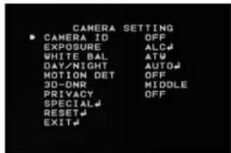
- Select [CAMERA ID] option on the [CAMERA SETTING] menu.
- Use [LEFT] or [RIGHT] to select a CAMERA ID (OFF, 1-255).
Menu Operation
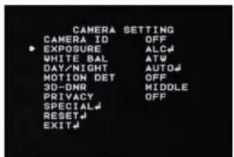
Exposure Settings
You can set the exposure options using the EXPOSURE menu.
- Select [EXPOSURE] option on the [CAMERA SETTING] menu.
- Use [LEFT] or [RIGHT] button to select a mode (ALC←→ ELC).
- Press [SET] button and the EXPOSURE menu appears.
BACKLIGHT setting
Use BACKLIGHT option to view the object clearly in back-light conditions.

- Select [BACKLIGHT] option.
- Use [LEFT] or [RIGHT] button to select a mode then press [SET].
- BLC: Camera's backlight compensation feature helps alleviate issues of visibility in high contrast areas. Set the BLC limit.
BLC LIMIT: LOW MIDDLE HIGH
Menu Operation
- HSBLC: Use for masking brightness of the specific area to view the subject more clearly. The HSBLC mode is automatically activated only in low luminance scene.
AREA SETTING: Use [LEFT] or [RIGHT] button to select a area then use [UP] or [DOWN] button to select a ON or OFF. Press [SET] to exit the Area setting menu.
GRAY SCALE: Use [LEFT] or [RIGHT] button to select a gray scale.
$$ (G R A Y \longleftrightarrow D. G R A Y \longleftrightarrow B L A C K). $$
USER SCALE: Use [LEFT] or [RIGHT] button to select a bright level.(5 level)
MASK: Use [LEFT] or [RIGHT] button to select [ON] or [OFF]. If you set the MASK to ON, the mask function is activate only when the HSBLC is automatically activated in low luminance scene.
• OFF: Not used.
Brightness setting
You can increase the brightness of the darkened video. If you set the brightness to lower value, the image is darkened. If you set the brightness to higher value, the image gets bright.

-
Select [BRIGHTNESS] option.
-
Use [LEFT] or [RIGHT] button to set the bright level.
Menu Operation
AGC (Automatic Gain Control) setting
If the images are too dark, change the maximum [AGC] value to make the images brighter.
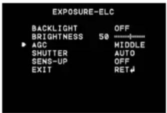
- Select [AGC] option.
- Use [LEFT] or [RIGHT] button to select a mode.
$$ (O F F \longleftrightarrow L O W \longleftrightarrow M I D D L E \longleftrightarrow H I G H) $$
SHUTTER (Shutter Speed) setting
Select the desired shutter speed for camera exposure. You can change the shutter speed to higher speed to capture fast-moving subjects, though the image becomes darker.
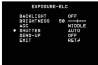
- Select [SHUTTER] option.
- Use [LEFT] or [RIGHT] button to set shutter speed. (AUTO↔OFF↔A.FLK↔1/160\~1/90000↔x512\~x2)
Menu Operation
SENS-UP setting
If pictures are not clear due to darkness, this SENS-UP operation would increase the sensitivity of picture.

- Use [UP] or [DOWN] button to select [SENS-UP] option.
- Use [LEFT] or [RIGHT] button to select mode.
• AUTO: Adjust the sensitivity of the picture automatically.
SENS-UP LIMIT: Use [LEFT] or [RIGHT] button to set the SENS-UP limit.
EXIT: Select a mode and press [SET] to exit the menu.
• OFF: Not used.
Note:
If you set to one of the SHUTTER options except AUTO on the [SHUTTER] menu or [AGC] to [OFF], the [SENS-UP] setting is not available and [---] mark is displayed.
White Balance settings
Select the method by which the camera shifts its output colors to compensate for the color of a light source.
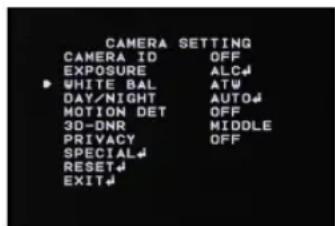
- Select [WHITE BAL] option.
- Use [LEFT] or [RIGHT] button to select a mode then
Menu Operation
press [SET].
- ATW (Auto-Tracing White Balance): The color temperature range for the proper white balance is approximately 1,700 - 11,000°K. Proper white balance may not be obtained under the following conditions:
The color temperature is out of the 1,700 - 11,000 °K range.
When the scene contains mostly high color temperature objects, such as a blue sky or sunset.
When the scene is dim.
- AWC→PUSH: If you select the AWC→PUSH mode, you will be able to set up the White Balance automatically using [SET] button.
• MANUAL: You can set the white balance options manually.
COLOR TEMP: Use [LEFT] or [RIGHT] button to select a function.
- INDOOR: The color temperature range for the proper white balance is approxi-
mately 3,200°K.
- OUTDOOR: The color temperature range for the proper white balance is approximately 5,100°K.
RED: Obtains the optimum amount of red gain.
BLUE: Obtains the optimum amount of blue gain.
Day/Night Setting

- Select [DAY/NIGHT] option.
- Use [LEFT] or [RIGHT] button to select mode for day/
Menu Operation
night function.
• AUTO: You will be able to change the Day/Night mode automatically.
Note:
If you set the AGC to [OFF] or the SHUTTER is set to one of the SHUTTER options except AUTO on the [EXPOSURE] menu, the AUTO mode of the DAY/NIGHT function is not available and [---] mark is displayed.
LEVEL: Use [LEFT] or [RIGHT] button to select a level. (LOW←→MIDDLE←→HIGH)
DWELL TIME: Use [LEFT] or [RIGHT] button to select a dwell time. (5, 10, 15, 30 or 60 SEC)
• DAY: Color mode enabled.
• NIGHT: Black-and-white mode enabled.
- EXT: Switches between color picture and black-and-white picture when an external day/night switching signal is received.
Motion Detection Setting
The motion detection detects the moving objects in the scene by monitoring changes in brightness level. You can select the level of sensitivity for motion detection to 4 zone.
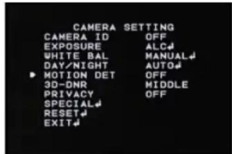
- Select [MOTION DET] option.
- Use [LEFT] or [RIGHT] button to select a [ON] and press [SET]. The MOTION DETECTION menu appears.
- Use [LEFT] or [RIGHT] button to select a zone number (AREA1 \~ AREA4) on the [ZONE NUMBER].
- Use [LEFT] or [RIGHT] button to set up the ON or OFF on the ZONE STATE.
Menu Operation
-
Use [UP] or [DOWN] to select an option then use [LEFT] or [RIGHT] button to adjust the option.
-
HEIGHT: Enlarge or decrease the vertical size of the mask.
-
WIDTH: Enlarge or decrease the horizontal size of the mask.
• MOVE Y: Moves vertical position of the mask.
• MOVE X: Moves horizontal position of the mask. -
Use [SENSITIVITY] option to obtain the optimum detection level.
3D-DNR Setting
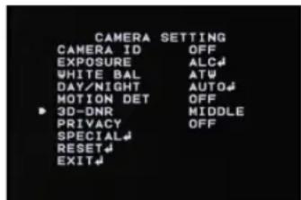
- Select [3D-DNR] option. If pictures are not clear due to brightness, this option would reduce the noise of picture.
- Use [LEFT] or [RIGHT] button to select a option. (OFF←→LOW←→MIDDLE←→HIGH)
Notes:
- If you set the AGC to [OFF] on the [EXPOSURE] menu, the [3D-DNR] function is not available and [---] mark is displayed.
- When you use this function, the afterimage may occur.
Menu Operation
Privacy Setting
This function is aiming at the protection of personal privacy, selecting a screen part black not to be displayed in the screen. Up to 8 zones can be registered.

- Select [PRIVACY] option.
- Use [LEFT] or [RIGHT] button to select a [ON] and press [SET]. The PRIVACY SETUP menu appears.
- Use [LEFT] or [RIGHT] button to select a mask (AREA1 \~ AREA8) on the [MASK NUMBER].
- Use [LEFT] or [RIGHT] button to set up the ON or OFF on the DISPLAY option.
- Use [LEFT] or [RIGHT] button to set up the GRAY,
WHITE or BLACK on the COLOR option.
- Use [UP] or [DOWN] to select an option then use [LEFT] or [RIGHT] button to adjust the option.
• HEIGHT: Enlarge or decrease the vertical size of the mask.
- WIDTH: Enlarge or decrease the horizontal size of the mask.
• MOVE Y: Moves vertical position of the mask.
• MOVE X: Moves horizontal position of the mask.
Note:
The parts with the registered mask numbers from AREA1 to AREA4 have the same color. (So do the parts with the numbers from AREA5 to AREA8). If you change the mask color, the registered mask color will be changed automatically with the same color for each of group (AREA1\~4, AREA5\~8).
Menu Operation
Special Menu Settings
This menu lets you adjust and set up D-ZOOM, D-EFFECT, SHARPNESS, STABILIZER, COLOR, SYNC, USER TITLE, LANGUAGE function by yourself in the SPECIAL menu.

-
Select [SPECIAL] option.
-
Press [SET] button and the SPECIAL menu appears.
Setting the D-ZOOM (Digital Zoom) level
You can select the digital zoom level.

- Select [D-ZOOM] option on the [SPECIAL] menu.
- Use [LEFT] or [RIGHT] button to select a [ON] then press [SET] the DIGITAL ZOOM menu appears. When you set to ON, the displayed image can be shaking.
- Use [UP] or [DOWN] to select a option then use [LEFT] or [RIGHT] button to select a level.
• ZOOM: Use [LEFT] or [RIGHT] button to enlarge the screen.
• PAN: Use [LEFT] or [RIGHT] button to move the screen. (left or right)
• TILT: Use [LEFT] or [RIGHT] button to move the screen. (up or down)
Menu Operation
Setting the D-EFFECT (Digital effect)
You can select the digital effect.

- Select [D-EFFECT] option on the [SPECIAL] menu.
- Use [LEFT] or [RIGHT] button to select a digital effect.
• V-FLIP: Flip the picture vertically.
• MIRROR: Turn on the mirror effect.
• ROTATE: Rotate the picture. (180°)
• OFF: Turn off the digital effect.
Setting the SHARPNESS effect
The degree to which the boundary of the two portions is clearly distinguished.

- Select [SHARPNESS] option on the [SPECIAL] menu.
- Use [LEFT] or [RIGHT] button to change a adjust the option. If you set the sharpness value to higher, the image outline becomes sharp. If you set to lower value, the image outline becomes dim.
Menu Operation
Stabilizer setting
The image stabilizer function minimizes the appearance of shaky images caused by low-frequency vibration.
This function is useful for outdoor surveillance.
Select [STABILIZER] option and set to ON or OFF.

Note:
If you set the [STABILIZER] to ON, the Digital zoom is set to [x1.1] automatically.
Setting the COLOR effect
You can switch the displayed picture to gray scale or color.
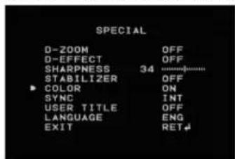
- Select [COLOR] option on the [SPECIAL] menu.
- Use [LEFT] or [RIGHT] button to change a color effect.
• ON: To display the picture with color.
• OFF: To display the picture with grayscale.
Menu Operation
Setting the SYNC (Synchronization)
The SYNC function is available only with AC power source.
- Select [SYNC] option on the [SPECIAL] menu.
- Use [LEFT] or [RIGHT] button to select [INT] or [LL] (Line Lock).
• INT: Selects for using the internal synchronization.
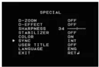
- LL (Line Lock): Selects for the operation of multi cameras because it synchronizes the camera phase by using the external signal (AC power signal).
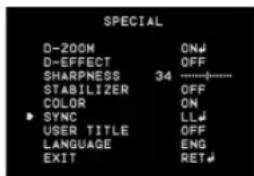

2-1. Select [LL] mode and press [SET].
2-2. Select a desired phase using the [LEFT] or [RIGHT] button.
Note:
When you use the DC 12V power, the [SYNC] option is fixed to [INT] mode only.
Setting the USER TITLE
You can use the camera identification to assign a number and character to the camera (0 - 9, A-Z, a-z).
The USER TITLE is displayed on the upper left of the screen. To disappear the user title, select [OFF].
- Select [USER TITLE] option on the [SPECIAL] screen.
- Use [LEFT] or [RIGHT] button to select a [ON] then
Menu Operation
press [SET]. The USER TITLE menu appears.

- Use [UP], [DOWN], [LEFT] or [RIGHT] button to select a character or number then press [SET] button.
• CLR: Clear all entered characters and numbers.
• POS: Move the USER TITLE position on the screen using the arrow buttons.
• END: Confirm your selection or exit the setting.
1 (Blank): Inserts a space at the cursor position.
/ Moves cursor to left or right.
Language Setting
Select the viewer language for the camera setup menu and OSD information display.

- Select [LANGUAGE] option on the [SPECIAL] screen.
- Press [LEFT] or [RIGHT] button to select a language.
Menu Operation
Reset Settings

- Select [RESET] option.
- Press [SET] button and the RESET menu appears.
- Use [UP] or [DOWN] to select option.

• CAMERA REBOOT: To reboot the camera system.
• FACTORY RESET: To reset the camera setting to factory setting, select [FACTORY RESET] option.
COMMUNICATION
PROTOCOL: Select a protocol for RS-232C TTL/RS-485 communication.
BAUD RATE: Set the speed of communication between the camera and the RS-232C TTL/RS-485 unit.
SAVE&REBOOT: To confirm the communication settings.
- Press [SET] button to confirm your selection.
Reference
RS-232C TTL/RS-485 Protocol (Optional)
Data Communication Format
• Data Length: 1 Byte (8 Bit)
• Start/Stop Bit: 1 Bit
- Parity Bit: None
• Baud rate: 9,600 bps
Format
| BYTE1 BYTE2 BYTE3 BYTE4 BYTE5 BYTE6 | |
| 0xE5 0x86 Camera ID | CODE1 CODE2 *C.S. |
*C.S. = Check Sum
• The data of total 6 bytes is transmitted from the external RS-485 device to the camera.
- BYTE 6: The value of Check Sum from 'BYTE 1' to 'BYTE 5'.
ex) In case of transmission, 0xC5, 0x5F, 0x02, 0x00, 0x0A"
$$ C. S. = 0 x C 5 + 0 x 5 F + 0 x 0 2 + 0 x 0 0 + 0 x 0 A = 0 x 0 1 3 0 $$
$$ \text { therefore, C.S. } = 0 \times 3 0 $$
Commands
| Function Command | |
| OSD Menu ON/OFF E5, 86, ID, 41, 02, C.S. | |
| LEFT Button E5, 86, ID, 12, 80, C.S. | |
| Right Button E5, 86, ID, 12, 90, C.S. | |
| Up Button E5, 86, ID, 11, 80, C.S. | |
| Down Button E5, 86, ID, 11, 90, C.S. | |
| Menu Button E5, 86, ID, 41, 01, C.S. |
Reference
Specification
| ITEM LSX701N LSX701P | ||
| Signal System NTSC PAL | ||
| Total/Effective Pixels 410K / 380K Pixels 470K / 440K Pixels | ||
| Pick-up Device 1/2" Interline EX-view HAD CCD | ||
| Lens C/CS Mount Lens | ||
| Signal Process XDI Slim | ||
| Synchronization System Internal / Line Lock | ||
| Scanning Frequency (H) 15.734 KHz 15.625KHz | ||
| Scanning Frequency (V) 59.94 Hz (VD) 50 Hz (VD) | ||
| Resolution | More than 650 TV Lines | |
| S/N Ratio | More Than 52dB (AGC Off, F1.2) | |
| Video Output Signal 1Vp-p Composite (75ohm) | ||
Reference
| ITEM LSX701N LSX701P | |||
| Minimum Illumination | Day 0.0001 | Lux (Sens-up Auto, F1.2) (0.06 Lux: Sens-Up Off, F1.2) | |
| Night 0.00001 | Lux (Sens-up Auto, F1.2) (0.0006 Lux: Sens-Up Off, F1.2) | ||
| Iris Control DC/VIDEO/ELC | |||
| Gain Control OFF/LOW/MIDDLE/HIGH | |||
| Exposure ALC/ELC | |||
| Shutter Speed 1/60 ~ 1/90,000 1/50 ~ 1/90,000 | |||
| White Balance ATW/MANUAL | |||
| Power Source DC 12V / AC24V | |||
| Power Consumption 4.4 W | |||
| Operation Temperature -10°C ~ 50°C (Humidity: 0%RH~80%RH) | |||
| Storage Temperature | -20°C ~ 60°C (Humidity: 0%RH~85%RH) | ||
| Weight | 420g | ||
| Dimension (H x V x D) | 67.4 x 61.5 x 134 mm | ||

LG
Life's Good
P/NO: MFL62723706


- Color Video Camera User Manual
- CAUTION
- REGULATORY INFORMATION: FCC Part 15
- Disposal of your old appliance
- This product is manufactured to comply with EMC Directive 2004/108/EC and Low Voltage Directive 2006/95/EC.
- Important Safety Instructions
- Cautions for Safe Operation
- Power Supply
- Note:
- Handling of the unit
- Operating and storage location
- Contents
- Features
- Part Names and Functions
- Lens mount cap
- Camera installation bracket
- Flange-back adjustment lever
- Lens iris output connector (LENS)
- Setup menu control buttons
- ALC Lens Setting Switch
- External Device Connectors
- Power indicator
- GND
- Video output connector (BNC type)
- Connections
- Precautions
- Connection Overview
- Connecting Display device
- Connecting Power Source
- Connecting RS-485/RS-232C TTL Device
- Connecting Alarm Device
- Contact Ratings
- Connecting Day&Night Switch
- Day function
- Night function
- Mounting the Lens
- 2-2. C mount type lens
- lens iris output connector
- Rewire the lens iris plug
- Concerning Auto-Iris Lenses
- DC type auto-iris lens
- CAUTION:
- ELC type auto-iris lens
- VIDEO type auto-iris lens
- Flange-back Adjustment
- Mounting the camera
- Menu Operation
- OSD Menu control buttons
- OSD Menu Overview
- General Operation
- Camera Identification Settings
- Exposure Settings
- BACKLIGHT setting
- Brightness setting
- SENS-UP setting
- White Balance settings
- press [SET].
- Day/Night Setting
- Motion Detection Setting
- 3D-DNR Setting
- Notes:
- Privacy Setting
- Special Menu Settings
- Setting the D-EFFECT (Digital effect)
- Setting the SHARPNESS effect
- Stabilizer setting
- Setting the COLOR effect
- Setting the SYNC (Synchronization)
- Setting the USER TITLE
- Language Setting
- Reset Settings
- Reference
- RS-232C TTL/RS-485 Protocol (Optional)
- Data Communication Format
Brand : LG
Model : LSX701P
Category : Unspecified