Stealthbox SB-J-JL4DPAS/10TW1-2 - Car Radio JL Audio - Free user manual and instructions
Find the device manual for free Stealthbox SB-J-JL4DPAS/10TW1-2 JL Audio in PDF.

User questions about Stealthbox SB-J-JL4DPAS/10TW1-2 JL Audio
0 question about this device. Answer the ones you know or ask your own.
Ask a new question about this device
Download the instructions for your Car Radio in PDF format for free! Find your manual Stealthbox SB-J-JL4DPAS/10TW1-2 - JL Audio and take your electronic device back in hand. On this page are published all the documents necessary for the use of your device. Stealthbox SB-J-JL4DPAS/10TW1-2 by JL Audio.
USER MANUAL Stealthbox SB-J-JL4DPAS/10TW1-2 JL Audio
a1 = 32( a1 - a2) , b1 = c_1 + 4

natural_image
Two black automotive speaker units with ventilation grilles and speaker holes (no text or symbols visible)Stealthbox®
INSTALLATION GUIDE for the
SB-J-JL4DDRV/10TW1-2
SB-J-JL4DDRV/10TW1-4
SKU# 94664 (2 Ω) & 94665 (4 Ω)
SB-J-JL4DPAS/10TW1-2
SB-J-JL4DPAS/10TW1-4
SKU# 94666 (2 Ω) & 94667 (4 Ω)
2018-Up Jeep Wrangler (JL) 4-Door
Enclosure Type: Sealed
Driver Type: 10TWI
Nominal Impedance: 2 or 4 ohms
Continuous Power Handling: 300 watts (RMS method)
SB-J-JL4DDRV/10TW1 & SB-J-JL4DPAS/10TW1 INSTR_SKU# 011510
! IMPORTANT
If you choose to perform the installation yourself, it is absolutely vital that the Stealthbox ^® be properly mounted to the vehicle according to these instructions. Failure to mount the enclosure properly presents two problems:
1) The sub-bass performance will suffer due to the movement of the enclosure caused by the force exerted by the woofer(s).
2) A loose enclosure presents a serious safety hazard in the event of a collision or sudden deceleration.
INSTALLATION DIFFICULTY:

ESTIMATED TIME: 2-3 HOURS

text_image
JL AUDIO ~ Quality & Design ~ SBX STEALTHBOX®Thank you for choosing a JL Audio Stealthbox* for your automotive sound system. With proper installation, your new vehicle-specific enclosed subwoofer system will deliver years of listening pleasure.
We strongly recommend that you have your new Stealthbox* installed by your authorized JL Audio dealer. The installation professionals employed by your dealer have the necessary tools and experience to disassemble and reassemble your vehicle properly. If you prefer to perform your own installation, please read this installation guide completely before beginning the process.
INCLUDED HARDWARE

text_image
BOM ID Qty SKU Description 1 5 153998 5/16 - 18 Hex Nut 2 5 150929 5/16" Split Lock Washer 3 5 153997 5/16" Oversized Flat Washer 4 2 153991 5/16" Rubber Sealing Washer 5 3 153994 5/16 - 18 x 1" Hex Head Bolt 6 3 153995 5/16" Flat Washer 7 4 153996 M6 x 45mm Socket Flanged Button Screw 8 2 153992 5/16" Retaining Washer 9 1 153776 1/4" Aluminum Spacer 10 1 153976 Mounting Bracket 11 2 153990 5/16 - 18 x 1-1/4" Square Neck Carriage Bolt - 8 154000 Fender Shield Retainer Clip (not shown) - 8 153999 1/4" x 2-3/16" Nylon Expansion Rivet (not shown)BOM ID Qty SKU Description
| 1 5 153998 | 5/16 - 18 Hex Nut | |
| 2 5 150929 | 5/16" Split Lock Washer | |
| 3 5 153997 | 5/16" Oversized Flat Washer | |
| 4 2 153991 | 5/16" Rubber Sealing Washer | |
| 5 3 153994 | 5/16 - 18 x 1" Hex Head Bolt | |
| 6 3 153995 | 5/16" Flat Washer | |
| 7 4 153996 | M6 x 45mm Socket Flanged Button Screw | |
| 8 2 153992 | 5/16" Retaining Washer | |
| 9 1 153776 | 1/4" Aluminum Spacer | |
| 10 1 153976 | Mounting Bracket | |
| 11 2 153990 | 5/16 - 18 x 1-1/4" Square Neck Carriage Bolt | |
| - 8 154000 | Fender Shield Retainer Clip (not shown) | |
| - 8 153999 | 1/4" x 2-3/16" Nylon Expansion Rivet (not shown) | |
POWER RECOMMENDATION
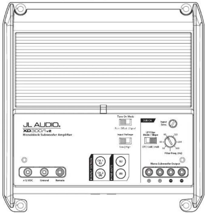
JL Audio recommends high quality amplifiers such as the JL Audio XD300/1v2. The diagram below shows the recommended crossover settings for the XD300/1v2. For a detailed description of the amplifier settings, consult the owner's manual for the amplifier. If another amplifier is being used, please reference this illustration and use similar settings on that amplifier.
text_image
JL AUDIO. XC300/1v2 Monoblock Subwoofer Amplifier +12 VDC Ground Remote Turn On Mode Max. Offset Signal Input Voltage Low High SUB CR Input Sens. LP Filter Mode / Slope OFF 12x8 24dB 80 120 60 200 500 Filter Freq (Hz) Multi Subwoofer OutputCONNECTIONS
Using quality power, signal, and speaker wire is essential in ensuring the performance of your Stealthbox®. JL Audio recommends using a 4 AWG power kit such as the XD-PCS4-1B for your Stealthbox® amplifier. Other kits are available should you be using more than one amplifier. Signal wire such as the JL Audio Premium Audio Interconnect Cables should be used to provide signal for both channels of the amplifier. JL Audio recommends using 12 AWG speaker wire for subwoofers such as our XC-BCS12-25.

natural_image
Interior view of a car engine bay with visible mechanical components and wiring (no text or symbols)STEP 1
NOTE: This manual illustrates the installation of the passenger side Stealthbox*. The installation procedure for the driver side Stealthbox® will be the same.
The rear wheel has been removed for illustrative purposes only. It will not be necessary to remove the wheel in most instances.
natural_image
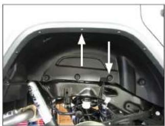
Interior view of a car hood with visible engine and mechanical components (no text or symbols)STEP 2
Locate the eight shield retainer clips and six nylon rivets that secure the inner fender liner to the vehicle.

natural_image
Close-up of a car's undercarriage showing the roof, dashboard, and engine components (no visible text or symbols)STEP 3
Unclip and remove the eight shield retainer clips.
natural_image
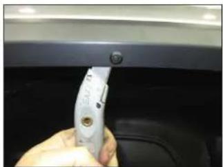
Close-up of a hand holding a white plastic tool against a dark background, no visible text or symbolsSTEP 4
Using a utility knife or diagonal cutters, carefully cut through the six nylon rivets between the inner fender liner and the plastic fender trim.
Note: Do not cut the two outermost nylon rivets. They do not need to be removed.
Remove the inner fender liner from the vehicle.
Page 4 • JL Audio, Inc., 2019 Continued on Next Page
SB-J-JL4DDRV/10TW1 & SB-J-JL4DPAS/10TW1 INSTR_SKU#011510
natural_image
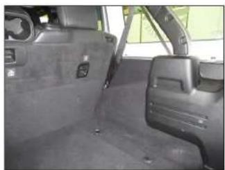
Interior view of a car showing the rear seats and side door, no visible text or symbolsSTEP 5
Empty the cargo area of the vehicle.

natural_image
Interior view of a car showing the rear seats and side door, no visible text or symbolsSTEP 6
Fold the seat back forward.
natural_image
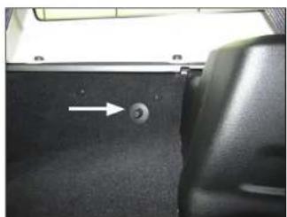
Interior view of a car showing a black seat with a white arrow pointing to a circular button (no text or symbols visible)STEP 7
Unclip and remove the carpet retainer clip. This will not be reinstalled.

natural_image
Interior view of a car showing the rear seats and dashboard (no visible text or symbols)STEP 8
Pull the carpet away from the wheel well.

natural_image
Hand placing a black plastic component into a car intake hood (no visible text or symbols)STEP 9
Position the Mounting Bracket as shown. The curved surface will rest on the contoured wheel well, and the indicated tab should be flush with the front edge of the raised rib.

natural_image
Close-up of a hand inserting a component into a car dashboard (no visible text or symbols)STEP 10
With the Mounting Bracket held in position, mark the location of the two indicated slots. Keep the Mounting Bracket in position for the next step.

natural_image
Close-up of a hand using a tool to adjust or install a black mechanical component (no visible text or symbols)STE P 11
With the Mounting Bracket in position, mark the location of the indicated hole. Remove the Mounting Bracket.

natural_image
Close-up of a car interior showing a hand holding a screwdriver, no visible text or symbolsSTEP 12
Using a step drill bit, carefully drill through the top ends of the marks made in Step 10, and enlarge the holes to 3/8".
Carefully drill through the mark made in Step 11, and enlarge the hole to 3/8".
Page 5 • J. Audio, Inc., 2019 Continued on Next Page
SB-J-JL4DDRV/10TW1 & SB-J-JL4DPAS/10TW1 INSTR_SKU#011510
natural_image
Close-up of a mechanical component with arrows pointing to features (no visible text or symbols)STEP 13
Pass a 5/16 - 18 x 1-1/4" Square Neck Carriage Bolt through the bottom of each of the square holes in the Mounting Bracket, as shown. Push a 5/16" Retaining Washer over each of the 5/16 - 18 x 1-1/4" Square Neck Carriage Bolts.
natural_image
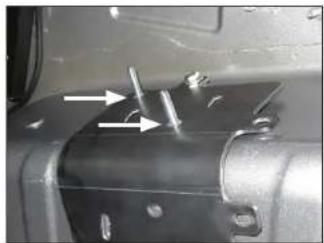
Close-up of a car's head panel with arrows pointing to specific components (no visible text or symbols)STEP 14
Slide a 5/16" Flat Washer over a 5/16 - 18 x 1" Hex Head Bolt, and pass the assembly through the upper hole in the Mounting Bracket, through a 1/4" Aluminum Spacer, and through the hole drilled in the wheel well.
Repeat the process for the lower holes, except without the spacers.
natural_image
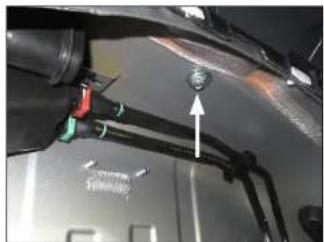
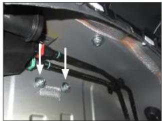
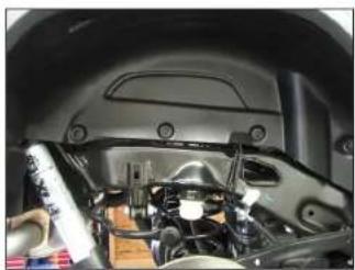
Close-up of a car's front suspension system with a valve and wiring (no visible text or symbols)STEP 15
From outside the vehicle, slide a 5/16" Oversized Flat Washer, a 5/16" Split Lock Washer, and a 5/16 - 18 Hex Nut over the upper 5/16 - 18 x 1" Hex Head Bolt, and hand tighten.
natural_image
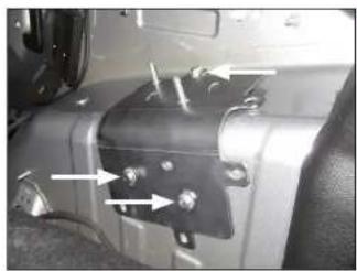
Close-up of a mechanical component with arrows pointing to specific parts (no visible text or symbols)STEP 16
Slide a 5/16" Oversized Flat Washer, a 5/16" Split Lock Washer, and a 5/16 - 18 Hex Nut each of the lower 5/16 - 18 x 1" Hex Head Bolts, and hand tighten.
Fully tighten the upper 5/16 - 18 Hex Nut installed in the previous step, then fully tighten the two lower 5/16 - 18 Hex Nuts.

natural_image
Hand holding a tool interacting with a black car trunk panel (no visible text or symbols)STEP 17
Push the carpet back down to the wheel well. Locate the locations of the two 5/16 - 18 x 1-1/4" Square Neck Carriage Bolts. Cut a small "X" in the carpet to allow the hardware to pass through.

natural_image
Close-up of a car's rear panel with two white arrows pointing to the side (no text or symbols visible)STEP 18
Pass the 5/16 - 18 x 1-1/4" Square Neck Carriage Bolts through the cuts in the carpet, as shown.

natural_image
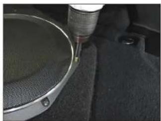
Close-up of a speaker grille component with a red-handled tool inserted, no visible text or symbolsSTEP 19
Remove the four M6 x 45mm Socket Flanged Button Screws from the front of the Stealthbox*.
natural_image
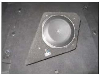
Close-up of a circular mechanical component with a hexagonal base and central hole, placed on a textured surface (no visible text or symbols)STEP 20
Remove the trim panel from the enclosure.
Page 6 • JL Audio, Inc., 2019 Continued on Next Page
SB-J-JL4DDRV/10TW1 & SB-J-JL4DPAS/10TW1 INSTR_SKU#011510
natural_image
Close-up of a precision tool applying material to a metal component (no visible text or symbols)STEP 21
Remove the eight subwoofer mounting screws. Disconnect the subwoofer, and remove it from the enclosure. Remove the batting from the enclosure.
natural_image
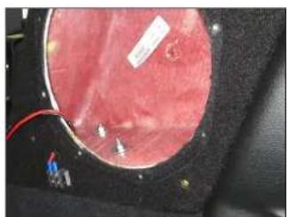
Close-up of a biological tissue section with visible internal structures and two white arrows indicating specific areas (no text or symbols present)STEP 22
Place the enclosure onto the wheel well, allowing the two 5/16 - 18 x 1-1/4" Square Neck Carriage Bolts to pass through the holes in the bottom of the enclosure.
natural_image
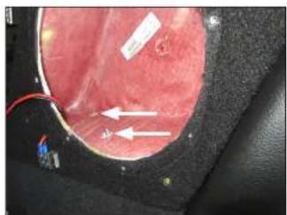
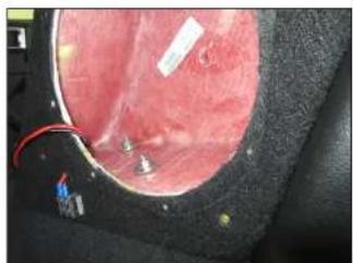
Close-up of a circular electronic device with red insulation and visible wiring (no text or symbols)STEP 23
Slide a 5/16" Oversized Flat Washer and a 5/16 - 18 Hex Nut over each of the 5/16 - 18 x 1-1/4" Square Neck Carriage Bolts, and fully tighten. This allows the enclosure to seat properly over the Mounting Bracket.
Remove the 5/16 - 18 Hex Nut and 5/16" Oversized Flat Washer from only one of the 5/16 - 18 x 1-1/4" Square Neck Carriage Bolts.
natural_image
Close-up of a medical procedure showing tissue and surgical instruments (no visible text or symbols)STEP 24
Slide a 5/16" Rubber Sealing Washer, the 5/16" Oversized Flat Washer, a 5/16" Split Lock Washer, and the 5/16 - 18 Hex Nut over the empty 5/16 - 18 x 1-1/4" Square Neck Carriage Bolt, and fully tighten.
Repeat the process for the other 5/16 - 18 x 1-1/4" Square Neck Carriage Bolt.
natural_image
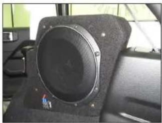
Interior view of a car showing a speaker grille mounted on a black textured base (no visible text or symbols)STEP 25
Reinstall the batting. Connect and reinstall the subwoofer and eight subwoofer mounting screws.
Connect speaker cable to the barrier strip on the front of the enclosure, and route the cable as necessary.
natural_image
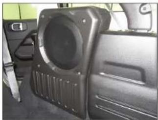
Interior view of a vehicle showing a black plastic door with a speaker grille and side panel (no visible text or symbols)STEP 26
Reinstall the trim panel and four M6 x 45mm Socket Flanged Button Screws. Use caution to not overtighten the screws.
Fold the seat back up.
natural_image
Close-up of a car's engine bay with visible components and wiring (no text or symbols)STEP 27
Reinstall the inner fender liner, and secure the inner portion with eight Fender Shield Retainer Clips.

natural_image
Close-up of a hand using a pliers to adjust or install a car engine compartment (no visible text or symbols)STEP 28
Using a poly hand riveter, secure the outer portion of the inner fender liner with six 1/4" x 2-3/16" Nylon Expansion Rivets.
Page 7 • J. Audio, Inc., 2019
SB-J-JL4DDRV/10TW1 & SB-J-JL4DPAS/10TW1 INSTR_SKU#011510
CONGRATULATIONS!
You have completed the installation for this model! Enjoy your new Stealthbox ^® !

natural_image
Interior view of a car showing rear seats, side seats, and dashboard (no visible text or symbols)MID/HIGH FREQUENCY DRIVER FITMENT
A variety of JL Audio coaxial and component systems will fit in the factory speaker locations of your vehicle.
| Location / OEMSpeaker Size | Suggested JL Audio Speaker Models | ||
| Coaxial Models Component Models | |||
| Dash | Upper / 3-1/2-inch | C2-350xC7-350cm | |
| Lower / 4-inch | C1-400x, C2-400xC5-400cm | ||
| Roll Bar | Outer / 3-1/2-inch | C2-350x | C7-350cm |
| Inner / 4-inch | C1-400x, C2-400xC5-400cm | ||
JLAUDIO. How we play.\*
| (954) 443-1100 | www.jleudio.com |
| At publication is noted in charge without notice. $ 2,000" and "How we play" are given during the event of 1. Auto, Inc. (New) or the Carer, Inc. (New) in https://www.jleudio.com. | |
| Filed on 05 - 2018. Leude, Inc. - Fromed to date when being posted on this new Jleudio.com. | |
JLA-SKU# 011510 • ver. 05.02.2019 • 10369 NORTH COMMERCIAL PARKWAY • MIRAMAR, FLORIDA • 33025 • USA

*011510*