D-921F - Blender TOA - Free user manual and instructions
Find the device manual for free D-921F TOA in PDF.

User questions about D-921F TOA
0 question about this device. Answer the ones you know or ask your own.
Ask a new question about this device
Download the instructions for your Blender in PDF format for free! Find your manual D-921F - TOA and take your electronic device back in hand. On this page are published all the documents necessary for the use of your device. D-921F by TOA.
USER MANUAL D-921F TOA
Thank you for purchasing TOA's Matrix System.
Please carefully follow the instructions in this manual to ensure long, trouble-free use of your equipment.
| CE1134 |
| TOA Electronics Europe GmbHSuederstrasse 282, 20537 Hamburg, GermanyThe year when the CE mark was affixed on the product is indicated by the first two digits of the serial number.1134-CPD-102 |
| EN 54-16: 2008Fire detection and fire alarm systems— Part 16: Voice alarm control and indicating equipmentOptions:Emergency microphone(s)Manual reset of the voice alarm conditionIndication of faults related to voice alarm zonesPhased evacuationVoice alarm condition output to CIERedundant power amplifiers |
When an EN 54-16 compliant SX-2000 system has to be installed, then read "APPENDIX: ADDITIONAL INSTALLATION INSTRUCTIONS FOR AN EN 54-16 COMPLIANT SYSTEM" in this document carefully and follow up the installation and configuration requirements explained herein. This APPENDIX contains the basic description of settings and installations, so please refer to the general instruction sections in this document for more details.
Note
Refer to the Instruction Manual attached to the VX-2000DS for the installation of the the VX-2000DS Emergency power supply, the VX-2000PF Power supply frame, and the VX-200PS Power supply unit.
TABLE OF CONTENTS
1. NOMENCLATURE AND FUNCTIONS
1.1.SX-2000SM System Manager 6
1.2. SX-2000AI Audio Input Unit 10
1.3. SX-2100AI Audio Input Unit 15
1.4.SX-2000AO Audio Output Unit 20
1.5. SX-2100AO Audio Output Unit 26
1.6. SX-2000CI Control Input Unit 32
1.7.SX-2000CO Control Output Unit 34
1.8. RM-200SF Fireman's Microphone 36
1.9.RM-200SA Remote Microphone 39
1.10. RM-210 Remote Microphone Extension 42
1.11. RM-200RJ Terminal Unit 43
1.12. Optional Modules
1.12.1. SX-200RM Remote Microphone Interface Module 44
1.12.2. D-921E Microphone/Line Input Module 45
1.12.3. D-921F Microphone/Line Input Module 45
1.12.4. D-922E Microphone/Line Input Module 46
1.12.5. D-922F Microphone/Line Input Module 46
1.12.6. D-936R Stereo Input Module 47
1.13. VP-2064, VP-2122, VP-2241, and VP-2421 Power Amplifiers 48
1.14. VP-200VX Power Amplifier Input Module 48
2. INSTALLATION
2.1. SX-2000SM
2.1.1. System reset enable/disable settings (DIP switch 3 operation) ...... 49
2.1.2. Failure reset operation method settings (DIP switch 4 operation) ..... 50
2.2. SX-2000AI and SX-2100AI
2.2.1. Module installation 51
2.2.2. Setting the device number 52
2.2.3. Changing the type of control outputs (SX-2100AI only) 53
2.3. SX-2000AO and SX-2100AO
2.3.1. Setting the device number 55
2.3.2. 24 V Emergency cutoff input settings (DIP switch 8 operation) (SX-2000AO only) .... 56
2.3.3. Converting an output into a transformer-balanced output (SX-2000AO only) 57
2.3.4. Changing the method of power supply for the control input signal applied to the Local Audio Control Input Terminal (SX-2100AO only) ..... 60
2.4.SX-2000CO 62
2.5. RM-200SF, RM-200SA, and RM-210
2.5.1. RM-200SF and RM-200SA device number settings (DIP switches 1 – 3 operation) 64
2.5.2. Adjusting microphone sensitivity (RM-200SF: DIP switch 5 operation or RM-200SA: DIP switch 4 operation) 66
2.5.3. CPU OFF function (general urgency all-call) settings (RM-200SF:DIP switch 6 operation or RM-200SA: DIP switch 5 operation) ..... 68
2.5.4. RM Communication function setting (RM-200SF: DIP switch 4 operation or RM-200SA: DIP switch 6 operation) .... 69
2.5.5. Using an external microphone (RM-200SA only) 70
2.5.6. Compressor function setting 72
2.5.7. Microphone fault detection function settings (RM-200SA only) 74
2.5.8. Installing the RM-200SF on a wall 75
2.5.9. RM-200SA expansion with the addition of the RM-210 (Installed on a flat surface) 79
2.5.10. Installing the RM-200SA on a wall 80
2.5.11. Installing the RM-210 on a wall 81
2.5.12. Creating remote microphone name labels 83
2.6. VP-2064, VP-2122, VP-2241 and VP-2421 Power Amplifiers
2.6.1. Removing the VP Power Amplifier's top panel 87
2.6.2. Changing the speaker line voltage 87
2.6.3. Installing the VP-200VX Power Amplifier Input Module in the VP Power Amplifiers 89
2.6.4. Ground lifting using the VP-200VX Power Amplifier Input Module 91
2.6.5. Replacing the blade fuse 92
2.7. Rack Mounting 93
3. SYSTEM CONFIGURATION EXAMPLE
3.1. System Configuration Example 1 94
3.2. System Configuration Example 2 95
4. CONNECTIONS
4.1. Removable Terminal Plug Connection 96
4.2. Input Equipment Connections
4.2.1. Connections of SX-2100AO's Local audio control input terminals 97
4.2.2. Connecting the SX-200RM to the RM-200SF or RM-200SA (via RM-200RJ as needed) 99
4.2.3. Connecting other input equipment 104
4.3. Output Equipment Connections
4.3.1. Connecting the SX-2000AO to power amplifiers 106
4.3.2. Connecting the SX-2100AO to power amplifiers and speakers 107
4.3.3. Connecting the SX-2100AO to external attenuators 108
4.3.4. Connecting the SX-2100AO to standby amplifiers 109
4.4. Control Input/Output Connections
4.4.1.SX-2000SM 110
4.4.2.SX-2100AI 112
4.4.3. SX-2000AO and SX-2100AO 115
4.4.4.SX-2000CI 118
4.4.5.SX-2000CO 119
4.5. SX Link Terminal Connections 120
4.5.1. Redundant configuration of switching hubs 121
4.5.2. Non-redundant configuration of switching hubs 122
4.6. CI/CO Link Terminal Connections
4.6.1. Connecting a single SX-2000CI or SX-2000CO 123
4.6.2. Connecting one each of SX-2000CI and SX-2000CO 123
4.7. Analog Link Terminal Connections 124
4.8. Connections to Use the Surveillance Function
4.8.1. Speaker line surveillance (SX-2100AO only) 125
4.8.2. Control line surveillance 129
5. SPEAKER LINE INITIAL SETTING
5.1. Setting Items ...... 130
5.2. OPEN/SHORT Criterion by Comparing the Current Value with the Initial Value 130
5.3. Setting Procedures
5.3.1. Summary setting procedures ...... 131
5.3.2. Screen display (Common) 133
5.3.3. Impedance initialization setting flow 134
5.3.4. Setting an initial impedance value 135
5.3.5. Adjusting the speaker line's OPEN sensitivity 137
5.3.6. Adjusting the speaker line's SHORT sensitivity 138
5.3.7. Clearing the settings 139
6. INSERTING A CF CARD
6.1. Using Settings Data 140
6.2. Inserting a CF Card (SX-2000SM: DIP switch 2 operation) 140
7. TIME SETTINGS 141
8. KEY LOCK SETTINGS AND CANCELLATION
8.1.SX-2000AI and SX-2100AI (DIP Switch 1 Operation) 142
8.2. SX-2000AO and SX-2100AO (DIP Switch 1 Operation) 143
9. OUTPUTTING LOG DATA
(SX-2000SM: DIP Switches 1 and 2 operations) 144
10. FAILURE INDICATIONS
10.1.SX-2000SM 145
10.2. SX-2000AI and SX-2100AI 146
10.3. SX-2000AO and SX-2100AO 148
10.4.SX-2000CI 149
10.5. SX-2000CO 150
10.6. RM-200SF and RM-200SA 150
11. SPECIFICATIONS
11.1. SX-2000SM System Manager 151
11.2. SX-2000AI Audio Input Unit 153
11.3. SX-2100AI Audio Input Unit 154
11.4. SX-2000AO Audio Output Unit 155
11.5. SX-2100AO Audio Output Unit 156
11.6. SX-2000CI Control Input Unit 158
11.7. SX-2000CO Control Output Unit 159
11.8. RM-200SF Fireman's Microphone 160
11.9. RM-200SA Remote Microphone 161
11.10. RM-210 Remote Microphone Extension 162
11.11.RM-200RJ Terminal Unit 162
11.12. SX-200RM Remote Microphone Interface Module 162
11.13. D-921E Microphone/Line Input Module 163
11.14. D-921F Microphone/Line Input Module 163
11.15. D-922E Microphone/Line Input Module 164
11.16. D-922F Microphone/Line Input Module 164
11.17. D-936R Stereo Input Module 164
11.18. VP-2064 Power Amplifier 4 x 60 W 165
11.19. VP-2122 Power Amplifier 2 x 120 W 166
11.20. VP-2241 Power Amplifier 1 x 240 W 167
11.21. VP-2421 Power Amplifier 1 x 420 W 168
11.22. VP-200VX Power Amplifier Input Module 168
APPENDIX: ADDITIONAL INSTALLATION INSTRUCTIONS FOR AN EN 54-16 COMPLIANT SYSTEM
1. GENERAL INFORMATION
1.1. Terms and Abbreviations ...... 169
1.2. Access Levels
1.2.1. Access level 1 ...... 169
1.2.2. Access level 2 ...... 169
1.2.3. Access level 3 ...... 170
1.2.4. Access level 4 170
1.3. Declaration for the VACIE SX-2000 according to EN54-16 §13.1.2 ...... 170
2. INDICATIONS AND CONTROLS IN ACCESS LEVEL 1
2.1. Mandatory Indications and Controls in Access Level 1 ...... 171
2.2. Options Requiring Indications and Controls in Access Level 1 172
2.3. Examples for the Mandatory Indications and Controls
2.3.1. Minimum configuration 173
2.3.2. Configuration with indication of faults in VA zones 174
3. INDICATIONS AND CONTROLS IN ACCESS LEVEL 2
3.1. Mandatory Control in Access Level 2 ...... 175
3.2. Options Requiring Controls in Access Level 2 ...... 176
3.3. Proposal for the Installation and Setting of an Emergency Microphone
3.3.1. Installation place 177
3.3.2. Settings 177
3.3.3. Example for a setting on an emergency microphone 177
4. OVERVIEW OF THE ACCESS LEVEL REQUIREMENTS
FOR THE EQUIPMENT AND RELATED FUNCTIONS .... 178
- POWER SUPPLY 178
- CABINETS 179
- STANDBY (RESERVE, REDUNDANT) AMPLIFIERS ...... 179
- SETTING ON THE SYSTEM MANAGER SX-2000SM 179
1. NOMENCLATURE AND FUNCTIONS
1.1. SX-2000SM System Manager
[Front]

text_image
LINK / ACT LAN SX LINK A SX LINK B MODE EMERGENCY CPU OFF STANDBY FAULT GENERAL CPU SX LINK TOA SX-B0000 SM MODE EMERGENCY CPU OFF STANDBY FAULT GENERAL CPU SX LINK FAULT ACI FAULT POWER RUN LAMP TEST SYSTEM MANAGER SX 2000SM Protective coverInside of the protective cover
flowchart
graph LR
    A["RESET"] --> B["USB"]
    B --> C["ACCESS"]
    C --> D["CF CARD"]
    D --> E["ON"]
    E --> F["SETTING"]
    style A fill:#fff,stroke:#000
    style B fill:#fff,stroke:#000
    style C fill:#fff,stroke:#000
    style D fill:#fff,stroke:#000
    style E fill:#fff,stroke:#000
    style F fill:#fff,stroke:#000
1. LAN Indicator [LAN] (Green)
Lights when the LAN connection terminal (31) on the rear panel is connected, and flashes during LAN communications.
2. SX Link A Indicator [SX LINK A] (Green)
Lights when the SX Link A terminal (29) on the rear panel is connected, and flashes while communications are being performed via the SX Link A terminal.
3. SX Link B Indicator [SX LINK B] (Green)
Lights when the SX Link B terminal (29) on the rear panel is connected, and flashes while communications are being performed via the SX Link B terminal.
4. Emergency Indicator [EMERGENCY] (Red)
Lights while the general urgency all-call is being made (p. 68) or when the SX-2000 system is in an emergency condition, and flashes when a 24 V emergency cutoff* state occurs involving any SX-2000AO within the system.
* In the SX-2000 system, a 24 V emergency cutoff input terminal that allows control of an emergency audio input is provided on the SX-2000AO's rear panel. When the SX-2000 system is combined with another emergency broadcast
system, a 24 V DC is normally kept being supplied to this emergency cutoff input terminal and is cut off (24 V emergency cutoff function) in emergency situations. This interrupts the general-purpose broadcast from the SX-2000, allowing the emergency broadcast system to override it. (For details, see p. 56.)
5. CPU OFF Indicator [CPU OFF] (Red)
Lights while the general urgency all-call (CPU OFF state) is being made (p. 68).
6. Standby Indicator [STANDBY] (Yellow)
Lights when the SX-2000 system is operating on the backup power supply during power failures. It also lights when the system reset cannot be performed using the SX-2000 Setting software. Note that if the standby indicator lights, it is not possible to restart your SX-2000SM using the Setting software.
To perform system reset, press the Reset key (15) inside the protective cover to restart.
7. General Indicator [GENERAL] (Yellow)
Lights while the general urgency all-call is being made (p. 68) or when a failure is detected in the SX-2000SM. Lights or flashes when a failure is detected in the system.
8. CPU Indicator [CPU] (Yellow)
Lights while the general urgency all-call is being made (p. 68) or when a failure is detected in the SX-2000SM.
9. SX Link Indicator [SX LINK] (Yellow)
Flashes when a cable is connected to neither the rear panel-mounted SX Link terminal A nor B.
10. Fault Ack Key [FAULT ACK]
The buzzer will sound when a failure is detected in the SX-2000 system. Press this key to stop the buzzer.
11. Fault Reset Key [FAULT RESET]
Pressing this key resets the failure information (the buzzer and fault indicators) for the entire SX-2000 system.
Set the mode for operation method using DIP switch 4 (19).
12. Lamp Test Key [LAMP TEST]
Used to test each indicator on the front panel of the SX-2000SM.
All Mode and Fault indicators (4) - (9) remain lit and the buzzer sounds as long as this key is pressed.
13. Power Indicator [POWER] (Blue)
Lights when the power is switched on.
14. RUN Indicator [RUN] (Green)
Normally flashes continuously.
Goes off while the general urgency all-call is being made (p. 68).
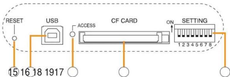
15. Reset Key [RESET]
Pressing this key reactivates the SX-2000SM. The entire system, including the SX-2000AI, SX-2100AI, SX-2000AO, and SX-2100AO is reactivated.
Notes
- Reactivating the system stops broadcasts currently in progress.
- Do not keep pressing the key for over 1 second. The unit cannot operate.
If the unit operation is suspended, press the Reset key for less than one second again.
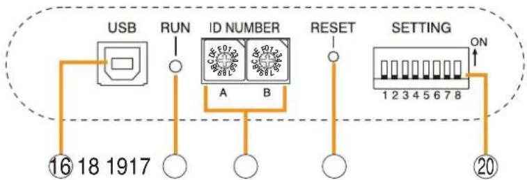
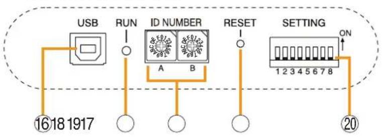
16. USB Port [USB]
This port is not used.
17. CF Card Access Indicator [ACCESS] (Green)
Flashes while reading from or writing to a CF card.
Note
Do not remove and reinsert the CF card nor operate the DIP switch (19) while this indicator is flashing.
18. CF Card Slot [CF CARD]
Use this slot to insert the CF card to operate settings data or write log data to the card.
- For settings data operation, see p. 140.
- For the method of writing log data, see p. 144.
Note
Removing and reinserting the CF card requires DIP switch settings. If the CF card is removed and reinserted without performing correct DIP switch settings, this may cause settings data loss or damage the card.
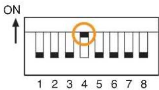
19. DIP Switch [SETTING]
- Switch 1
Used to read log data (p. 144).
ON: Allows log data to be written into the CF card.
OFF: Normally select this position.
- Switch 2
Used to perform CF card access settings (p. 140).
ON: Stops access to the CF card.
OFF: Normally select this position.
- Switch 3
Set whether or not to enable online control using the SX-2000 Setting Software (p. 49).
ON: Disables online writing of settings data and system reset.
OFF: Normally select this position.
- Switch 4
Set the method of operation to reset the failure information (the buzzer and fault indicators) with the FAULT RESET key (11) (p. 50).
In the same manner as the FAULT RESET key operation, the failure information can also be reset by shorting the RES terminals of the Data input terminals (26) at the timing set here.
ON: Sets to the accidental operation prevention mode.
OFF: Sets to the one touch mode.
(For the operation methods in each individual mode, see the separate Operating Instructions, "Detecting Fault.")
- Switches 5 - 8
These switches are not used.
Note
Switches 1 - 8 are set to the OFF position by default.
[Rear]
![TOA D-921F - [Rear] - 1](/content/2026/06/1214100/images/6bd4a10aa34260dbc59dd7de01acedaf9027f288da9f92cdc9f75a1010b63146.jpg)
text_image
DC POWER IN 24 19 4 3 2 OUTPUT C. NO. STATUS OUTPUT OUTPUT ANALOG LINK OUT2 OUT1 SX LINK B A LAN 0 21 22 23 24 25 26 27 28 29 30 31 32 20 0 0 0 0 0 0 0 0 0 0 0 0 0 0 0 0 0 0 0 0 0 0 0 0 0 0 0 0 0 0 0 0 0 020. Functional Earth Terminal [SIGNAL GND]
Hum noise may be generated when external equipment is connected to the unit. Connecting this terminal to the functional earth terminal of the external equipment may reduce the hum noise.
Note: This terminal is not for protective earth.
21. DC Power Input Terminal [DC POWER IN]
Connect an optional DC power supply unit to this terminal. Select the DC power supply source with consideration given to the current power consumption of the system the SX-2000SM is to be connected to. When not using a redundant power system*, connect the [+] terminal of input A to the [+] terminal of input B, and the [-] terminal of input A to the [-] terminal of input B. (Refer to the Instruction Manual attached to the VX-2000DS.)
* A method of connecting separate power sources to each power input or connecting the commercial power supply and backup power supply separately to each power input to prevent the system from going down when a cable is broken or power fails.
22. DS Link Terminals [DS LINK]
Connect either terminal to the DS-SF Link terminal of the VX-2000DS.
23. Status Output Terminals [STATUS OUTPUT]
Relay make contact outputs. Each contact capacity is rated at 40 V DC for withstand voltage, and 2 mA – 300 mA for control current. The number of outputs is 4. The RJ45 connector's pin arrangement is as follows:
[Upper row]
![TOA D-921F - [Upper row] - 1](/content/2026/06/1214100/images/b5b71f603fa5b672d4b5c1fb44d46cb438dba080310098a5cd5f86fa61f76a2a.jpg)
| Pin 4 | Pin 3 | Pin 2 | Pin 1 |
| Not used | CPUFAULT | CPU CPUFAULT FAULT | |
| NC | NO | COM | |
| Pin 8 | Pin 7 | Pin 6 | Pin 5 |
| GENERAL FAULT | GENERAL FAULT | Not used | GENERAL FAULT |
| NC | NO | COM |
- CPU FAULT
CPU irregularity in progress: Pin 1 – Pin 2 shorted Normal: Pin 1 – Pin 3 shorted
- GENERAL FAULT
Some irregularity in progress: Pin 5 – Pin 7 shorted Normal: Pin 5 – Pin 8 shorted
[Lower row]
![TOA D-921F - [Lower row] - 1](/content/2026/06/1214100/images/b75a74186ab6687df962237bb82160f699767125ddcf83ba27e9c09c5130f927.jpg)
| Pin 1 | Pin 2 | Pin 3 | Pin 4 |
| BUZZER | BUZZER | BUZZER | Not used |
| COM | NO | NC |
| Pin 5 | Pin 6 | Pin 7 | Pin 8 |
| CPU OFF | Not used | CPU OFF | CPU OFF |
| COM | NO | NC |
• BUZZER
Buzzer ON: Pin 1 – Pin 2 shorted Buzzer OFF: Pin 1 – Pin 3 shorted
- CPU OFF
Remote microphone-initiated general urgency all-call broadcasts in progress:
Pin 5 – Pin 7 shorted.
General urgency all-call broadcasts not initiated:
Pin 5 – Pin 8 shorted.
[RJ45 connector's pin No. vs. Cable color]
| RJ45's pin No. | Cable color (T568B type) (T568A type) | Cable color |
| 1 | Orange/White | Green/White |
| 2 | Orange | Green |
| 3 | Green/White | Orange/White |
| 4 | Blue | Blue |
| 5 | Blue/White | Blue/White |
| 6 | Green | Orange |
| 7 | Brown/White | Brown/White |
| 8 | Brown | Brown |
| Shield | — | — |
24. Control Output Terminals [OUTPUT C1 - C8]
Relay make contact outputs. Each contact capacity is rated at 40 V DC for withstand voltage, and 2 mA – 300 mA for control current.
These terminals are controlled by the SX-2000 Setting Software. (See the separate Setting Software Instructions, "Pattern Settings.")
25. 24V DC Output Terminals [DC OUT]
These terminals can provide up to 100 mA of 24 V DC power to connected external equipment.
26. Data Input Terminals [ACK/RES/LAMP]
Photo coupler inputs. A current of approximately 2 mA flows when shorted, and the voltage becomes approximately 24 V DC when opened.
• ACK
The buzzer may sound when a failure is detected in the SX-2000SM.
Short the ACK terminals to stop the buzzer.
If a failure occurs while ACK is on, it is automatically received.
These terminals serve the same function as the front-mounted FAULT ACK key (10).
• RES
In accordance with the DIP switch 4 (19) setting, shorting these terminals resets once the failure information (the buzzer and fault indicators) of the SX-2000SM.
These terminals serve the same function as the front-mounted FAULT RESET key (11).
• LAMP
Used to test the indicators on the SX-2000SM's front panel. All MODE and FAULT indicators (4) – (9) remain lit and the buzzer sounds as long as these terminals are set to ON.
27. Control Input Terminals [INPUT C1 - C8]
Photo coupler inputs. A current of approximately 2 mA flows when shorted, and the voltage becomes approximately 24 V DC when opened. Functions can be assigned to these terminals using the SX-2000 Setting Software. (See the separate Setting Software Instructions, "Event Settings.")
28. Analog Link Output Terminals [ANALOG LINK OUT 1/2]
Connect these terminals to the analog link input terminals of the SX-2000AI, SX-2100AI, SX-2000AO, or SX-2100AO.
![TOA D-921F - Analog Link Output Terminals [ANALOG LINK OUT 1/2] - 1](/content/2026/06/1214100/images/a6e3eb2ad1ae41abdfac1b0709bf8921ef006ce4f07079956c4f3941a412e8f1.jpg)
text_image
ANALOG LINK OUT2 OUT1 LINK RESET LINK STATUS 1 2 3 4| Function LED On LED | Off | |
| 1. OUT 2 connection confirmation | Connected | Unconnected |
| 2. OUT RESET output | Resetting | Normal |
| 3. OUT 1 connection confirmation | Connected | Unconnected |
| 4. OUT STANDBY start output | Start | Normal |
29. SX Link Terminals [SX LINK A/B]
Use switching hubs to connect between the SX link terminals of the SX-2000SM, SX-2000AI, SX-2100AI, SX-2000AO, and SX-2100AO.
Connect each of the SX Links A and B to the same switching hub*, or to different switching hubs* that have been connected in star configuration.
Notes
- Be sure to connect both terminals of A and B.
• After connection completion, press the Reset key to reactivate the SX-2000SM.
* Contact your TOA dealer for more information on switching hubs.

text_image
SX LINK B A LINK IN USE LINK IN USE 1 2 3 4| Function | LED On/Flashing | LED Off |
| 1. B connection confirmation | Connected | Unconnected |
| 2. B operation in progress indication | Operating | Not operating |
| 3. A connection confirmation | Connected | Unconnected |
| 4. A operation in progress indication | Operating | Not operating |
30. MAC Address for SX Link Connections
MAC address to be used for SX link connection.
31. LAN Connection Terminal [LAN]
Used when setting times to be recorded in operation logs.
Connect this terminal to a switching hub that supports the 10BASE-T or 100BASE-TX standard. Since time settings can also be performed via a PC, connect the PC to the switching hub as well.
Notes
- Do not connect the switching hub to the LAN.
- Avoid directly connecting the SX-2000SM to the PC via a cross cable.
(See the separate Setting Software Instructions "Basic Settings" for settings related to the SX-2000SM's IP address, etc.)
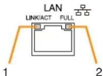
| Function LED On/Flashing LED Off | ||
| 1. Connection confirmation | Connected | Unconnected |
| 2. Full duplex communication detection | Detected | Undetected |
31. MAC Address for LAN Connection
A 12-digit hexadecimal address number peculiar to and assigned to the network-connected unit.
1.2. SX-2000AI Audio Input Unit
[Front]
text_image
①2 3 114 5 6 7 8 9 10 TOA P1 P2 P3 P4 三式-驱动驱动 AI INPUT1 INPUT2 INPUT3 INPUT4 INPUT5 INPUT6 INPUT7 INPUT8 ON/OFF POWER CPU OFF STANDARD MONITOR ON/OFF AUDIO INPUT UNIT SK-2000W Protective cover ⑫ 13 14 15Inside of the protective cover
flowchart
graph TD
    A["USB"] --> B["16"]
    B --> C["18"]
    C --> D["1917"]
    E["RUN"] --> F["○"]
    G["ID NUMBER"] --> H["A"]
    G --> I["B"]
    J["RESET"] --> K["○"]
    L["SETTING"] --> M["1 2 3 4 5 6 7 8"]
    M --> N["ON"]
    N --> O["20"]
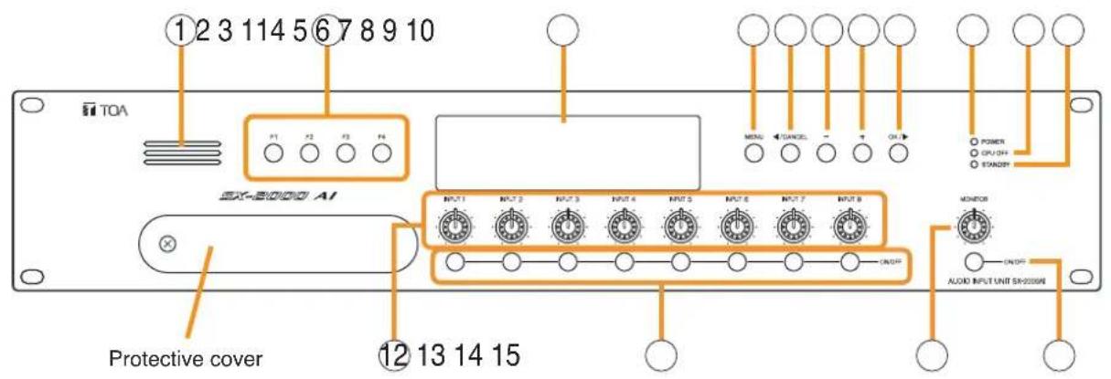
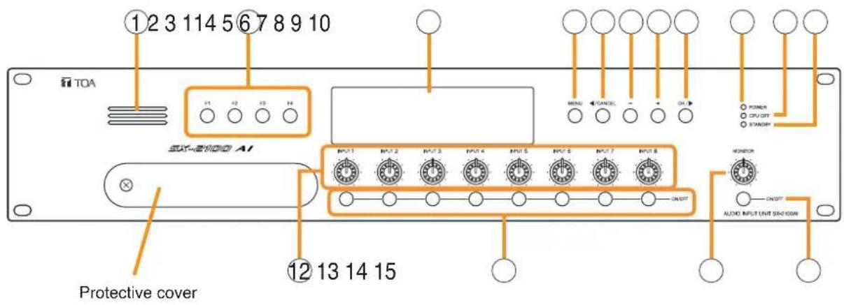
1. Monitor Speaker
Allows any input channel to be monitored.
2. Function Keys [F1, F2, F3, F4]
Pressing a function key executes the function that has been assigned to that key using the SX-2000 Setting Software.
(See the separate Setting Software Instructions, "Event Settings.")
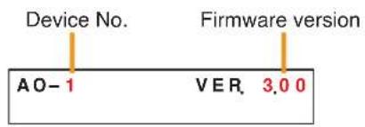
3. Fluorescent Display
The default display shows device numbers and firmware versions.

text_image
Device No. A I - 1 Firmware version VER . 3.0 0Displays the SX-2000AI's current operation status, input level, etc. (See the separate Operating Instructions, "SX-2000AI Audio Input Unit.")
4. Menu Key [MENU]
Pressing this key displays the fluorescent display's menu screen. Whenever this key is pressed, the screen returns to the default display for whatever portion of the menu screen is displayed.
5. Cancel Key [ /CANCEL]
Used to switch the menu screen.
6. Minus Key [-]
Used to switch the menu screen. When the Monitor ON/OFF Key (15) is set to ON, use this key to select which channel to monitor.
The selected channel number decreases by one each time this key is pressed.
7. Plus Key [+]
Used to switch the menu screen. When the Monitor ON/OFF Key (15) is set to ON, use this key to select which channel to monitor.
The selected channel number increases by one each time this key is pressed.
8. OK Key [OK/]
Used to switch the menu screen.
9. Power Indicator [POWER] (Blue)
Lights when the power is switched on.
10. CPU OFF Indicator [CPU OFF] (Red)
Lights while the general urgency all-call (CPU OFF state) is being made (p. 68).
11. Standby Indicator [STANDBY] (Green)
Lights while the unit is being initialized at power-on or at reset.
Flashes when the fluorescent display is in light shutoff mode and the light stays unlit.
Lights when the SX-2000 system is operating on the backup power supply during power failures.
12. Input Volume Controls [INPUT 1 - 8]
Adjust the input volume of each input channel. Rotating the control fully counterclockwise mutes the input sound source connected to that channel and causes the input ON/OFF indicator (28) on the fluorescent display to turn off.
When an input channel's "Type" is set to "Emergency" on the SX-2000 Setting software, the input signal source is made to bypass this Input volume control. (See the separate Setting Software Instructions, "System Settings.")
13. Channel Keys [ON/OFF]
Turn each input channel on or off. The input channel alternates between on and off each time this key is pressed.
Other functions can also be assigned to each key by using the SX-2000 Setting Software. (See the separate Setting Software Instructions, "Event Settings.")
When an input channel's "Type" is set to "Emergency" on the SX-2000 Setting software, the input signal source is made to bypass this Channel key. (See the separate Setting Software Instructions, "System Settings.")
14. Monitor Volume Control [MONITOR]
Adjusts the sound volume of the monitor speaker (1).
15. Monitor ON/OFF Key [ON/OFF]
Enables or disables the audio monitor function for the selected input channel. The monitor function alternates between on and off each time this key is pressed.
16. USB Port [USB]
This port is not used.
17. RUN Indicator [RUN] (Green)
Normally flashes continuously.
18. ID Switch [ID NUMBER]
Sets the SX-2000AI's device number.
(See p. 52.)
19. Reset Key [RESET]
Pressing this key resets the SX-2000AI.
Notes
- Resetting the SX-2000AI stops broadcasts in a part of or all zones currently in progress via the reset SX-2000AI.
- Do not keep pressing the key for over 1 second. The unit cannot operate.
If the unit operation is suspended, press the Reset key for less than one second again.
20. DIP Switch [SETTING]
Performs key lock function settings.
(See p. 142.)
- Switch 1
ON: Disables operation of the front panel input volume controls and channel keys.
OFF: Cancels key lock status.
- Switches 2 - 8
These switches are not used.
Note
Switches 1 - 8 are set to the OFF position by default.
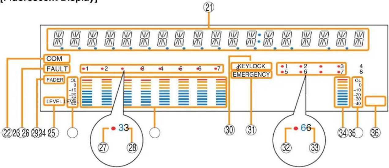
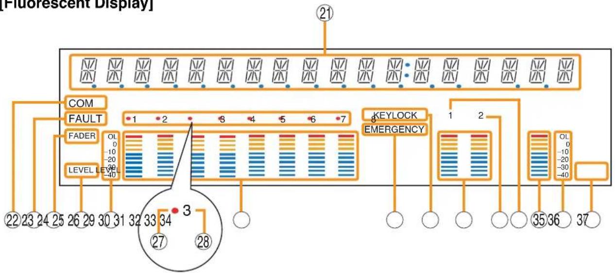
[Fluorescent Display]

flowchart
graph TD
    A["COM"] --> B["FAULT"]
    B --> C["FADER"]
    C --> D["LEVEL LEVEL"]
    D --> E["22 23 26"]
    E --> F["21"]
    B --> G["1 2 8 4 5 6 7"]
    G --> H["30 31"]
    B --> I["KEYLOCK"]
    I --> J["EMERGENCY"]
    J --> K["30 31"]
    J --> L["34 35"]
    L --> M["36"]
    B --> N["33"]
    N --> O["27 28"]
    O --> P["30 31"]
    O --> Q["34 35"]
    Q --> R["36"]
Notes
- A timer-activated light shutoff function can be set for the fluorescent display using the SX-2000 Setting Software. (See the separate Setting Software Instructions, "Basic Settings.")
When the light shutoff function has been set, if the SX-2000AI is not operated for 5 minutes or more, the fluorescent display's light goes off and the standby indicator (11) begins to flash. Pressing any keys other than the function keys on the front panel resets the screen display.
• Normally, the fluorescent display's light goes off at the time of the power failure.
- While the SX-2000 system is in an emergency condition, the fluorescent display's light does not go off even if the power fails.
21. Text Display Area
Displays the menu screen information when the corresponding function key is pressed.
22. COM Indicator [COM]
Flashes to indicate a communications error.
23. Fault Indicator [FAULT]
Flashes when a system failure, incorrect system configuration* or communications error is detected. This indicator continues to flash until failure conditions return to normal.
* When the system or module configuration differs from the contents set by the SX-2000 Setting Software.
24. Input Level Meter Fader Indicator [FADER]
Lights when the input level meter indicates the sound volume set using the SX-2000 Setting Software or input volume control.
25. Input Level Meter Level Indicator [LEVEL]
Lights when the input level meter indicates the level being input to the SX-2000AI.
26. Input Level Meter Scale
27. Input Indicator
The input channel to be monitored lights red.
28. Input ON/OFF Indicator
Indicates the unit's operating status when the corresponding channel key is pressed.
The indicator state differs depending on the function assigned to each channel key as follows.
| Function assigned to the channel key | When ON | When OFF |
| Input ON/OFF | Lights* | Unlit |
| General-purpose pattern broadcast's activation and termination | Flashes | Lights |
* The indicator state is "Unlit" when the input volume is muted.
29. Input Level Meter
Indicates the actual level or a set volume value on each input channel.
30. Key Lock Indicator [KEY LOCK]
Lights when the input volume controls and channel keys are locked. (See p. 142, "Key Lock Settings and Cancellation.")
31. Emergency Indicator [EMERGENCY]
Lights when the SX-2000 system is in an emergency condition.
32. Remote Microphone Output Status Indicator
Lights red continuously as long as announcements are made from the RM-200SF, RM-200SA, or RM-210 Remote Microphone.
- Remote Microphone Connection Status Indicator The device number of the Remote Microphone connected to the SX-2000AI lights.
34. Monitor Level Meter
Indicates the sound volume level of the input channel being monitored.
35. Monitor Level Meter Scale
Lights when the monitor ON/OFF key (15) is set to ON.
36. Monitor ON/OFF Indicator [LEVEL]
Lights when the monitor ON/OFF key (15) is set to ON.
[Rear]
![TOA D-921F - Monitor ON/OFF Indicator [LEVEL] - 1](/content/2026/06/1214100/images/ed05836a56ba4582e1e29dd774b07f8629440017ed329c0a3d59f3b3e0a5555e.jpg)
text_image
③7 ③8 ③9 ④0 41 42 43 44 45 ANALOG LINK OUT IN SX LINK B A 4637. DC Power Input Terminal [DC POWER IN]
Connect an optional DC power supply unit to this terminal. Select the DC power supply source with consideration given to the current power consumption of the system the SX-2000AI is to be connected to. When not using a redundant power system*, connect the [+] terminal of input A to the [+] terminal of input B, and the [-] terminal of input A to the [-] terminal of input B. (Refer to the Instruction Manual attached to the VX-2000DS.)
* A method of connecting separate power sources to each power input or connecting the commercial power supply and backup power supply separately to each power input to prevent the system from going down when a cable is broken or power fails.
38. Module Slot 3 [3]
Slot for input channels 5 and 6.
39. Module Slot 1 [1]
Slot for input channels 1 and 2.
40. Functional Earth Terminal [SIGNAL GND]
Hum noise may be generated when external equipment is connected to the unit. Connecting this terminal to the functional earth terminal of the external equipment may reduce the hum noise.
Note: This terminal is not for protective earth.
41. Module Slot 4 [4]
Slot for input channels 7 and 8.
42. Module Slot 2 [2]
Slot for input channels 3 and 4.
43. Analog Link Output Terminal [ANALOG LINK OUT]
Connect this terminal to the analog link input terminal of the SX-2000AI, SX-2100AI, SX-2000AO, or SX-2100AO.
![TOA D-921F - Analog Link Output Terminal [ANALOG LINK OUT] - 1](/content/2026/06/1214100/images/6ca608087876e5bef18164e393e8771b4da14a88e1bed4837e007a5bc3690d83.jpg)
text_image
ANALOG LINK OUT IN STATUS LINK RESET UNK 1 2| Function LED On LED Off | ||
| 1. Not used | ||
| 2. OUT connection confirmation | Connected U | hconnected |
44. Analog Link Input Terminal [ANALOG LINK IN]
Connect this terminal to the analog link output terminal of the SX-2000SM, SX-2000AI, SX-2100AI, SX-2000AO, or SX-2100AO.
![TOA D-921F - Analog Link Input Terminal [ANALOG LINK IN] - 1](/content/2026/06/1214100/images/1ec66da3c7992208466a5349d6c1aef9618c5339979fe691ee4ca40ca3eac314.jpg)
text_image
ANALOG LINK OUT IN STATUS LINK RESET LINK 3 4| Function LED On LED Off | ||
| 3. RESET input | Resetting Normal | |
| 4. Not used | ||
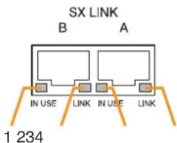
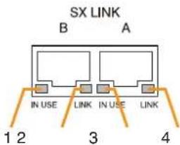
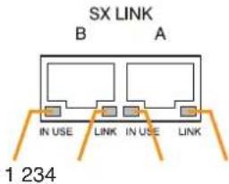
45. SX Link Terminals [SX LINK A/B]
Use switching hubs to connect between the SX link terminals of the SX-2000SM, SX-2000AI, SX-2100AI, SX-2000AO, and SX-2100AO. Connect each of the SX Links A and B to the same switching hub*, or to different switching hubs* that have been connected in star configuration.
Notes
- Be sure to connect both terminals of A and B.
- After connection completion, press the Reset key to reactivate the SX-2000AI.
* Contact your TOA dealer for more information on switching hubs.
text_image
SX LINK B A IN USE LINK IN USE LINK 1 234| Function | LED On/Flashing | LED Off |
| 1. B operation in progress indication | Operating Not operating | |
| 2. B connection confirmation | Connected Unconnected | |
| 3. A operation in progress indication | Operating Not operating | |
| 4. A connection confirmation | Connected Unconnected | |
46. MAC Address
MAC address to be used for SX link connection.
1.3. SX-2100AI Audio Input Unit
[Front]
text_image
①2 3 114 5 6 7 8 9 10 TOA ②1 ③ ④ ⑤ ⑥ ⑦ ⑧ ⑨ ⑩ ⑪ ⑫ ⑬ ⑭ ⑮ ⑯ ⑰ ⑱ ⑲ ⑳ ⑴ ⑵ ⑶ ⑷ ⑧ ⑨ ⑩ ⑪ ⑫ ⑬ ⑭ ⑮ ⑯ ⑰ ⑱ ⑲ ⑳ ⑪ ⑫ ⑬ ⑭ ⑮ ⑯ ⑰ ⑱ ⑲ ⑳ ⑪ ⑫ ⑬ ⑭ ⑮ ⑯ ⑰ ⑱ ⑲ ⑳ ⑪ ⑫ ⑬ ⑭ ⑮ ⑯ ⑰ ⑱ ⑲ ⑳ ⑪ ⑫ ⑬Inside of the protective cover
flowchart
graph TD
    A["USB"] --> B["16 18 1917"]
    C["RUN"] --> D["○"]
    E["ID NUMBER"] --> F["A"]
    E --> G["B"]
    H["RESET"] --> I["○"]
    J["SETTING"] --> K["1 2 3 4 5 6 7 8"]
    L["ON"] --> M["20"]
1. Monitor Speaker
Allows any input channel to be monitored.
2. Function Keys [F1, F2, F3, F4]
Pressing a function key executes the function that has been assigned to that key via the SX-2000 Setting Software.
(See the separate Setting Software Instructions, "Event Settings.")
3. Fluorescent Display
The default display shows device numbers and firmware versions.

text_image
Device No. A I - 1 Firmware version VER . 3.0 0Displays the SX-2100AI's current operation status, input level, etc. (See the separate Operating Instructions, "SX-2100AI Audio Input Unit.")
4. Menu Key [MENU]
Pressing this key displays the fluorescent display's menu screen. Whenever this key is pressed, the screen returns to the default display for whatever portion of the menu screen is displayed.
5. Cancel Key [CANCEL]
Used to switch the menu screen.
6. Minus Key [-]
Used to switch the menu screen. When the Monitor ON/OFF Key (15) is set to ON, use this key to select which channel to monitor. The selected channel number decreases by one each time this key is pressed.
7. Plus Key [+]
Used to switch the menu screen. When the Monitor ON/OFF Key (15) is set to ON, use this key to select which channel to monitor. The selected channel number increases by one each time this key is pressed.
8. OK Key [OK/]
Used to switch the menu screen.
9. Power Indicator [POWER] (Blue)
Lights when the power is switched on.
10. CPU OFF Indicator [CPU OFF] (Red)
Lights while the general urgency all-call (CPU OFF state) is being made (p. 68).
11. Standby Indicator [STANDBY] (Green)
Lights while the unit is being initialized at power-on or at reset.
Flashes when the fluorescent display is in light shutoff mode and the light stays unlit.
Lights when the SX-2000 system is operating on the backup power supply during power failures.
12. Input Volume Controls [INPUT 1 - 8]
Adjust the input volume of each input channel. Rotating the control fully counterclockwise mutes the input sound source connected to that channel and causes the input ON/OFF indicator (28) on the fluorescent display to turn off.
When an input channel's "Type" is set to "Emergency" on the SX-2000 Setting software, the input signal source is made to bypass this Input volume control. (See the separate Setting Software Instructions, "System Settings.")
13. Channel Keys [ON/OFF]
Turn each input channel on or off. The input channel alternates between on and off each time this key is pressed.
Other functions can also be assigned to each key by using the SX-2000 Setting Software. (See the separate Setting Software Instructions, "Event Settings.")
When an input channel's "Type" is set to "Emergency" on the SX-2000 Setting software, the input signal source is made to bypass this Channel key. (See the separate Setting Software Instructions, "System Settings.")
14. Monitor Volume Control [MONITOR]
Adjusts the sound volume of the monitor speaker (1).
15. Monitor ON/OFF Key [ON/OFF]
Enables or disables the audio monitor function for the selected input channel. The monitor function alternates between on and off each time this key is pressed.
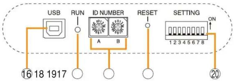
16. USB Port [USB]
This port is not used.
17. RUN Indicator [RUN] (Green)
Normally flashes continuously.
18. ID Switch [ID NUMBER]
Sets the SX-2100AI's device number.
(See p. 52.)
19. Reset Key [RESET]
Pressing this key resets the SX-2100AI.
Notes
- Resetting the SX-2100AI stops broadcasts in a part of or all zones currently in progress via the reset SX-2100AI.
- Do not keep pressing the key for over 1 second. The unit cannot operate.
If the unit operation is suspended, press the Reset key for less than one second again.
20. DIP Switch [SETTING]
Performs key lock function settings.
(See p. 142.)
- Switch 1
ON: Disables operation of the front panel input volume controls and channel keys.
OFF: Cancels key lock status.
- Switches 2 – 8
These switches are not used.
Note
Switches 1 - 8 are set to the OFF position by default.
[Fluorescent Display]
flowchart
graph TD
    A["COM"] --> B["FAULT"]
    B --> C["FADER"]
    C --> D["LEVEL LEVEL"]
    D --> E["KEYLOCK EMERGENCY"]
    E --> F["Keylock"]
    style A fill:#f9f,stroke:#333
    style B fill:#ccf,stroke:#333
    style C fill:#cfc,stroke:#333
    style D fill:#fcc,stroke:#333
    style E fill:#ffc,stroke:#333
    style F fill:#fcc,stroke:#333
Notes
- A timer-activated light shutoff function can be set for the fluorescent display using the SX-2000 Setting Software. (See the separate Setting Software Instructions, "Basic Settings.")
When the light shutoff function has been set, if the SX-2100AI is not operated for 5 minutes or more, the fluorescent display's light goes off and the standby indicator (11) begins to flash. Pressing any keys other than the function keys on the front panel resets the screen display. - Normally, the fluorescent display's light goes off at the time of the power failure.
- While the SX-2000 system is in an emergency condition, the fluorescent display's light does not go off even if the power fails.
21. Text Display Area
Displays the menu screen information when the corresponding function key is pressed.
22. COM Indicator [COM]
Flashes to indicate a communications error.
23. Fault Indicator [FAULT]
Flashes when a system failure, incorrect system configuration* or communications error is detected. This indicator continues to flash until failure conditions return to normal.
* When the system or module configuration differs from the contents set by the SX-2000 Setting Software.
24. Input Level Meter Fader Indicator [FADER]
Lights when the input level meter indicates the sound volume set using the SX-2000 Setting Software or input volume control.
25. Input Level Meter Level Indicator [LEVEL]
Lights when the input level meter indicates the level being input to the SX-2100AI.
26. Input Level Meter Scale
27. Input Indicator
The input channel to be monitored lights red.
28. Input ON/OFF Indicator
Indicates the unit's operating status when the corresponding channel key is pressed.
The indicator state differs depending on the function assigned to each channel key as follows.
| Function assigned to the channel key | When ON | When OFF |
| Input ON/OFF | Lights* | Unlit |
| General-purpose pattern broadcast's activation and termination | Flashes | Lights |
* The indicator state is "Unlit" when the input volume is muted.
29. Input Level Meter
Indicates the actual level or a set volume value on each input channel.
30. Key Lock Indicator [KEY LOCK]
Lights when the input volume controls and channel keys are locked. (See p. 142, "Key Lock Settings and Cancellation.")
31. Emergency Indicator [EMERGENCY]
Lights when the SX-2000 system is in an emergency condition.
32. Remote Microphone Output Status Indicator
Lights red continuously as long as announcements are made from the RM-200SF, RM-200SA, or RM-210 Remote Microphone.
33. Remote Microphone Connection Status Indicator
The device number of the Remote Microphone connected to the SX-2100AI lights.
34. Monitor Level Meter
Indicates the sound volume level of the input channel being monitored.
35. Monitor Level Meter Scale
Lights when the monitor ON/OFF key (15) is set to ON.
36. Monitor ON/OFF Indicator [LEVEL]
Lights when the monitor ON/OFF key (15) is set to ON.
[Rear]
![TOA D-921F - Monitor ON/OFF Indicator [LEVEL] - 1](/content/2026/06/1214100/images/65d73edea1744dbdb7efa6bbb0d74e688e4ab86095bff9c91342ef726c3823f3.jpg)
text_image
3837 39 43 44 45 46 CONTROL OUTPUT C: C: C: C: C: C: C: C: C: C: C: C: C: C: C: C: C: C: C: C: C: C: C: C: C: C: C: C: C: C: C: C: C: C: C: C: C: C: C: C: C: C: C: C: C: C: C: C: C: C: C: CONTROL INPUT C: C: C: C: C: C: C: C: C: C: C: C: C: C: C: C: C: C: C: C: C: C: C: C: C: C: C: C: C: C: C: C: C: ANALOG LINK OUT IN SX LINK S B A 50 47 48 49 40 41 4237. DC Power Input Terminal [DC POWER IN]
Connect an optional DC power supply unit to this terminal. Select the DC power supply source with consideration given to the current power consumption of the system the SX-2100AI is to be connected to. When not using a redundant power system*, connect the [+] terminal of input A to the [+] terminal of input B, and the [-] terminal of input A to the [-] terminal of input B.
(Refer to the Instruction Manual attached to the VX-2000DS.)
* A method of connecting separate power sources to each power input or connecting the commercial power supply and backup power supply separately to each power input to prevent the system from going down when a cable is broken or power fails.
38. Module Slot 3 [3]
Slot for input channels 5 and 6.
39. Module Slot 1 [1]
Slot for input channels 1 and 2.
40. Functional Earth Terminal [SIGNAL GND]
Hum noise may be generated when external equipment is connected to the unit. Connecting this terminal to the functional earth terminal of the external equipment may reduce the hum noise.
Note: This terminal is not for protective earth.
41. Module Slot 4 [4]
Slot for input channels 7 and 8.
42. Module Slot 2 [2]
Slot for input channels 3 and 4.
43. Control Output Terminals
[CONTROL OUTPUT 1 - 16]
Relay make contact outputs.
All the contact outputs are of normally open type when shipped from the factory.
Each output can be converted into normally closed type by changing the internal jumper setting. (See "Operation of Power Feed Jumper and Isolation Jumper" on the next page.)
Each contact capacity is rated at 40 V DC for withstand voltage, and 2 mA – 300 mA for control current. These terminals are controlled by the SX-2000 Setting Software. (See the separate Setting Software Instructions, "Pattern Settings.")
44. Isolation Jumper [GND]
The supplied removable terminal plug is equipped with a jumper. When the jumper is attached, the [-] terminals of all inputs (1 – 16) are connected to the internal power supply. Removing the jumper disconnects and isolates these [-] terminals from this unit. (See "Operation of Power Feed Jumper and Isolation Jumper" on the next page.)
45. Power Feed Jumper [VCC]
The supplied removable terminal plug is equipped with a jumper. When the jumper is attached, the circuits of all control inputs (1 – 16) are powered from inside the SX-2100AI. Removing the jumper disconnects this internal power supply and thus requires that power be supplied externally to the circuit. (See "Operation of Power Feed Jumper and Isolation Jumper" on the next page.)
46. Control Input Terminals [CONTROL INPUT 1 - 16]
Photo coupler inputs. A current of approximately 2 mA flows when shorted, and the voltage becomes under 40 V DC when opened.
The input of 100 msec or greater is required to operate. These contact inputs can be isolated from the SX-2100AI unit by cutting the power feed jumper (45) and the isolation jumper (44). Each contact input when isolated is 40 V DC for maximum applied voltage and approximately 2 mA for the loop current. Since each terminal is equipped with a current limiter employing constant current circuitry, there is no need to limit current on the external equipment side. The [-] terminals of all control inputs are common. Use the SX-2000 Setting Software to assign functions to these terminals. (See the separate Setting Software Instructions, "Event Settings.")
47. Analog Link Output Terminal [ANALOG LINK OUT]
Connect this terminal to the analog link input terminal of the SX-2000AI, SX-2100AI, SX-2000AO, or SX-2100AO.
![TOA D-921F - Analog Link Output Terminal [ANALOG LINK OUT] - 1](/content/2026/06/1214100/images/22e4d945b07daa3d6317d020b7e8272d01b082c3ca2b1f361c4ffc75132ab1b1.jpg)
text_image
ANALOG LINK OUT IN STATUS LINK RESET LINK 1 2| Function LED On LED Off | ||
| 1. Not used | ||
| 2. OUT connection confirmation | Connected Unconnected | |
48. Analog Link Input Terminal [ANALOG LINK IN]
Connect this terminal to the analog link output terminal of the SX-2000SM, SX-2000AI, SX-2100AI, SX-2000AO, or SX-2100AO.
![TOA D-921F - Analog Link Input Terminal [ANALOG LINK IN] - 1](/content/2026/06/1214100/images/dd5f90478610ae16d3c1d2483fbe2f45c31232f87877f68c2764d1f15e49797b.jpg)
text_image
ANALOG LINK OUT IN STATUS LINK RESET LINK 3 4| Function LED On LED Off | ||
| 3. RESET input Resetting Norma | ||
| 4. Not used | ||
49. SX Link Terminals [SX LINK A/B]
Use switching hubs to connect between the SX link terminals of the SX-2000SM, SX-2000AI, SX-2100AI, SX-2000AO, and SX-2100AO. Connect each of the SX Links A and B to the same switching hub*, or to different switching hubs* that have been connected in star configuration.
Notes
- Be sure to connect both terminals of A and B.
• After connection completion, press the Reset key to reactivate the SX-2100AI.
* Contact your TOA dealer for more information on switching hubs.
text_image
SX LINK B A IN USE LINK IN USE LINK 1 2 3 4| Function | LED On/Flashing | LED Off |
| 1. B operation in progress indication | Operating Not operating | |
| 2. B connection confirmation | Connected Unconnected | |
| 3. A operation in progress indication | Operating Not operating | |
| 4. A connection confirmation | Connected Unconnected | |
50. MAC Address
MAC address to be used for SX link connection.
[Operation of Power Feed Jumper and Isolation Jumper]

flowchart
graph TD
    A["Power feed jumper"] --> B["Photo coupler"]
    B --> C["Internal circuit"]
    D["VCC"] --> A
    E["GND"] --> F["Isolation jumper"]
    G["Control input"] --> H["-"]
    H --> I["+"]
    I --> B
    J["Ground"] --> B
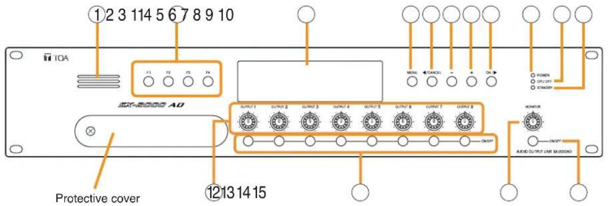
1.4. SX-2000AO Audio Output Unit
[Front]
text_image
①2 3 114 5 6 7 8 9 10 TOA F1 F2 F3 F4 EXT-20000 AO OUTPUT 1 OUTPUT 2 OUTPUT 3 OUTPUT 4 OUTPUT 5 OUTPUT 6 OUTPUT 7 OUTPUT 8 MONITOR AUDIO OUTPUT UNIT SKX20000 Protective cover ⑫13 14 15Inside of the protective cover

flowchart
graph TD
    A["USB"] --> B["16 18 1917"]
    C["RUN"] --> D["○"]
    E["ID NUMBER"] --> F["A"]
    E --> G["B"]
    H["RESET"] --> I["○"]
    J["SETTING"] --> K["1 2 3 4 5 6 7 8"]
    L["ON"] --> M["20"]
1. Monitor Speaker
Allows any output channel to be monitored.
2. Function Keys [F1, F2, F3, F4]
Pressing a function key executes the function that has been assigned to that key via the SX-2000 Setting Software.
(See the separate Setting Software Instructions, "Event Settings.")
3. Fluorescent Display
The default display shows device numbers and firmware versions.

text_image
Device No. A O- 1 Firmware version V E R. 3,0 0Displays the SX-2000AO's current operation status, output level, etc. (See the separate Operating Instructions, "SX-2000AO Audio Output Unit.")
4. Menu Key [MENU]
Pressing this key displays the fluorescent display's menu screen. Whenever this key is pressed, the screen returns to the default display for whatever portion of the menu screen is displayed.
5. Cancel Key [CANCEL]
Used to switch the menu screen.
6. Minus Key [-]
Used to switch the menu screen. When the Monitor ON/OFF Key (15) is set to ON, use this key to select which channel to monitor. The selected channel number decreases by one each time this key is pressed.
7. Plus Key [+]
Used to switch the menu screen. When the Monitor ON/OFF Key (15) is set to ON, use this key to select which channel to monitor. The selected channel number increases by one each time this key is pressed.
8. OK Key [OK/]
Used to switch the menu screen.
9. Power Indicator [POWER] (Blue)
Lights when the power is switched on.
10. CPU OFF Indicator [CPU OFF] (Red)
Lights while the general urgency all-call (CPU OFF state) is being made (p. 68).
11. Standby Indicator [STANDBY] (Green)
Lights while the unit is being initialized at power-on or at reset.
Flashes when the fluorescent display is in light shutoff mode and the light stays unlit.
Lights when the SX-2000 system is operating on the backup power supply during power failures.
12. Output Volume Controls [OUTPUT 1 - 8]
Adjust the output volume of each output channel. Rotating the control fully counterclockwise mutes the output volume and causes the output ON/OFF indicator (28) on the fluorescent display to turn off.
Signals on the output channel being used for emergency broadcast are made to bypass this Output volume control.
13. Channel Keys [ON/OFF]
Turn each output channel on or off. The output channel alternates between on and off each time this key is pressed.
Other functions can also be assigned to each key by using the SX-2000 Setting Software. (See the separate Setting Software Instructions, "Event Settings.")
Signals on the output channel being used for emergency broadcast are made to bypass this Channel key.
14. Monitor Volume Control [MONITOR]
Adjusts the sound volume of the monitor speaker (1).
15. Monitor ON/OFF Key [ON/OFF]
Enables or disables the audio monitor function for the selected output channel. The monitor function alternates between on and off each time this key is pressed.
16. USB Port [USB]
This port is not used.
17. RUN Indicator [RUN] (Green)
Normally flashes continuously.
18. ID Switch [ID NUMBER]
Sets the SX-2000AO's device number.
(See p. 55.)
19. Reset Key [RESET]
Pressing this key resets the SX-2000AO.
Notes
- Resetting the SX-2000AO stops broadcasts currently in progress via the reset SX-2000AO.
- Do not keep pressing the key for over 1 second. The unit cannot operate.
If the unit operation is suspended, press the Reset key for less than one second again.
20. DIP Switch [SETTING]
- Switch 1
Performs key lock function settings. (See p. 143.)
ON: Disables operation of the front panel output volume controls and channel keys.
OFF: Cancels key lock status.
- Switches 2 – 7
These switches are not used.
- Switch 8
Enables or disables the 24 V emergency cutoff input on the rear panel. (See p. 56.)
Note
Switches 1 - 8 are set to the OFF position by default.
[Fluorescent Display]

flowchart
graph TD
    A["COM"] --> B["FAULT"]
    B --> C["FADER"]
    C --> D["LEVEL LEVEL"]
    D --> E["KEYLOCK EMERGENCY"]
    E --> F["OL"]
    style A fill:#f9f,stroke:#333
    style B fill:#ccf,stroke:#333
    style C fill:#cfc,stroke:#333
    style D fill:#fcc,stroke:#333
    style E fill:#ffc,stroke:#333
    style F fill:#cff,stroke:#333
Notes
- A timer-activated light shutoff function can be set for the fluorescent display using the SX-2000 Setting Software. (See the separate Setting Software Instructions, "Basic Settings.")
When the light shutoff function has been set, if the SX-2000AO is not operated for 5 minutes or more, the fluorescent display's light goes off and the standby indicator (11) begins to flash. Pressing any keys other than the function keys on the front panel resets the screen display.
- Normally, the fluorescent display's light goes off at the time of the power failure.
- While the SX-2000 system is in an emergency condition, the fluorescent display's light does not go off even if the power fails.
21. Text Display Area
Displays the menu screen information when the corresponding function key is pressed.
22. COM Indicator [COM]
Flashes to indicate a communications error.
23. Fault Indicator [FAULT]
Flashes when a system failure, incorrect system configuration*1 or communications error is detected. This indicator continues to flash until failure conditions return to normal.
*1 When the system or module configuration differs from the contents set by the SX-2000 Setting Software.
24. Output Level Meter Fader Indicator [FADER]
Lights when the output level meter indicates the sound volume set using the SX-2000 Setting Software or output volume control.
25. Output Level Meter Level Indicator [LEVEL]
Lights when the output level meter indicates the level being output from the SX-2000AO.
26. Output Level Meter Scale
27. Output Indicator
The output channel to be monitored lights red.
28. Output ON/OFF Indicator
Indicates the unit's operating status when the corresponding channel key is pressed.
The indicator state differs depending on the function assigned to each channel key as follows.
| Function assigned to the channel key | When ON | When OFF |
| Output ON/OFF | Lights* | Unlit |
| General-purpose pattern broadcast's activation and termination | Flashes | Lights |
* The indicator state is "Unlit" when the output volume is muted.
29. Output Level Meter
Indicates the actual level or a set volume value on each output channel.
30. Emergency Indicator [EMERGENCY]
Lights when the SX-2000 system is in an emergency condition.
When the 24 V emergency cutoff input ^*2 is enabled, this indicator flashes if the input receives an emergency signal.
*2 The SX-2000AO has a 24 V emergency cutoff input terminal (49) on the rear panel, allowing control of an emergency audio input. When the SX-2000 system is combined with an emergency broadcast system, a 24 V DC is normally kept being supplied to this emergency cutoff input terminal and is cut off (24 V emergency cutoff function) in emergency situations. This interrupts the general-purpose broadcast from the SX-2000 system, allowing the emergency broadcast system to override it. (For details, see p. 56.)
Note
When the 24 V Emergency cutoff input is set to be disabled (not usable) with the DIP switch 8 inside the protective cover, the Emergency indicator will not flash even if 24 V DC supply to this input terminal is cut off.
31. Key Lock Indicator [KEY LOCK]
Lights when the output volume controls and channel keys are locked. (See p. 143, "Key Lock Settings and Cancellation.")
32. Control Input Unit Connection Indicator [1]
Indicates "1" when the SX-2000CI is connected to the SX-2000AO.
33. Control Output Unit Connection Indicator [2]
Indicates "2" when the SX-2000CO is connected to the SX-2000AO.
34. Monitor Level Meter
Indicates the sound volume level of the output channel being monitored.
35. Monitor Level Meter Scale
Lights when the monitor ON/OFF key (15) is set to ON.
36. Monitor ON/OFF Indicator [LEVEL]
Lights when the monitor ON/OFF key (15) is set to ON.
[Rear]
![TOA D-921F - Monitor ON/OFF Indicator [LEVEL] - 1](/content/2026/06/1214100/images/12420369081cc65def508deb1ae987853ec65761915d94ad931c160737694330.jpg)
text_image
DC POWER IN A B CONTROL OUTPUT C 100 C 100 C 100 C 100 C 100 C 100 C 100 C 100 C 100 C 100 C 100 C 100 C 100 C 100 C 100 C 100 C 100 C 100 C 100 C 100 C 100 40 43 46 47 474849 CICO LINK ENERGENCY UNT OFF LINE INPUT DC/MV INPUT ANALOG LINK OUT IN SX LINK B A 5051 5253 37883937. Functional Earth Terminal [SIGNAL GND]
Hum noise may be generated when external equipment is connected to the unit. Connecting this terminal to the functional earth terminal of the external equipment may reduce the hum noise.
Note: This terminal is not for protective earth.
38. DC Power Input Terminal [DC POWER IN]
Connect an optional DC power supply unit to this terminal. Select the DC power supply source with consideration given to the current power consumption of the system the SX-2000AO is to be connected to. When not using a redundant power system*, connect the [+] terminal of input A to the [+] terminal of input B, and the [-] terminal of input A to the [-] terminal of input B. (Refer to the Instruction Manual attached to the VX-2000DS.)
* A method of connecting separate power sources to each power input or connecting the commercial power supply and backup power supply separately to each power input to prevent the system from going down when a cable is broken or power fails.
39. Control Output Terminals
[CONTROL OUTPUT 1 - 8]
Relay make contact outputs.
Each contact capacity is rated at 40 V DC for withstand voltage, and 2 mA – 300 mA for control current.
These terminals are controlled by the SX-2000 Setting Software. (See the separate Setting Software Instructions, "Pattern Settings.")
40. Power Feed Jumper 2 [VCC]
The supplied removable terminal plug is equipped with a jumper.
When the jumper is attached, the circuits of control inputs 3, 4, 7, and 8 are powered from inside the SX-2000AO.
Removing the jumper disconnects this internal power supply and thus requires that power be supplied externally to the circuit. (See "Operation of Power Feed Jumper and Isolation Jumper" on the next page.)
41. Isolation Jumper 2 [GND]
The supplied removable terminal plug is equipped with a jumper.
When the jumper is attached, the [-] terminals of control inputs 3, 4, 7, and 8 are connected to the internal power supply.
Removing the jumper disconnects and isolates these [-] terminals from this unit. (See "Operation of Power Feed Jumper and Isolation Jumper" shown below.)
42. Control Input Terminals
[CONTROL INPUT 1 - 8]
Photo coupler inputs.
A current of approximately 2 mA flows when shorted, and the voltage becomes under 40 V DC when opened. The input of 100 msec or greater is required to operate.
These contact inputs can be isolated from the SX-2000AO unit by cutting power feed jumpers 1 (43) and 2 (40) and isolation jumpers 1 (44) and 2 (41). Each contact input when isolated is 40 V DC for maximum applied voltage and approximately 2 mA for the loop current.
Since each terminal is equipped with a current limiter employing constant current circuitry, there is no need to limit the current on the external equipment side.
The [-] terminals of 1, 2, 5, and 6 are common, while those of 3, 4, 7, and 8 are common.
Use the SX-2000 Setting Software to assign functions to these terminals. (See the separate Setting Software Instructions, "Event Settings.")
43. Power Feed Jumper 1 [VCC]
The supplied removable terminal plug is equipped with a jumper.
When the jumper is attached, the circuits of control inputs 1, 2, 5, and 6 are powered from inside the SX-2000AO.
Removing the jumper disconnects this internal power supply and thus requires that power be supplied externally to the circuit. (See "Operation of Power Feed Jumper and Isolation Jumper" shown below.)
44. Isolation Jumper 1 [GND]
The supplied removable terminal plug is equipped with a jumper.
When the jumper is attached, the [-] terminals of control inputs 1, 2, 5, and 6 are connected to the internal power supply.
Removing the jumper disconnects and isolates these [-] terminals from this unit. (See "Operation of Power Feed Jumper and Isolation Jumper" shown below.)
45. Audio Output Terminals [LINE OUTPUT]
Output audio signals to be broadcast.
These outputs are electronically balanced, but can be converted into transformer-balanced type using optional IT-450 transformers. (See p. 57, "Converting an output into a transformer-balanced output.")
Note
Each output cannot be converted into unbalanced type as it is electronically balanced.
To convert each output into unbalanced type, use an optional IT-450 transformer.
46. CI/CO Link Terminal [CI/CO LINK]
Connect this terminal to the CI/CO Link Data Terminal of the SX-2000CI or SX-2000CO.
47. CI/CO Link Connection Indicator [LINK] (Green)
Lights when the SX-2000CI or the SX-2000CO is connected.
48. Emergency Audio Input Terminal [EMERGENCY LINE INPUT]
Connect a voice evacuation system equipment to this terminal. The input signal is routed to all audio output terminals when the SX-2000AO is turned off or 24 V DC is not applied to the 24 V Emergency cutoff input terminal (49).
49. 24 V Emergency Cutoff Input Terminal [EMERGENCY CUTOFF DC24 V INPUT]
Controls the Emergency audio input. Input current is under 5 mA.
[Operation of Power Feed Jumper and Isolation Jumper]
![TOA D-921F - 24 V Emergency Cutoff Input Terminal [EMERGENCY CUTOFF DC24 V INPUT] - 1](/content/2026/06/1214100/images/e05c39fcf9a41aae7198a1a9d757ee349e5289d336c2e6653c434d20be531999.jpg)
flowchart
graph TD
    A["Power feed jumper"] --> B["Photo coupler"]
    B --> C["Internal circuit"]
    D["VCC"] --> A
    E["Control input"] --> F["-"]
    F --> G["+"]
    H["Isolation jumper"] --> I["GND"]
    J["Ground"] --> B
50. Analog Link Output Terminal [ANALOG LINK OUT]
Connect this terminal to the analog link input terminal of the SX-2000AI, SX-2100AI, SX-2000AO, or SX-2100AO.
![TOA D-921F - Analog Link Output Terminal [ANALOG LINK OUT] - 1](/content/2026/06/1214100/images/98cd549aad89689da4e0c9eaaf4a3707390511f97a43d1e79beab15148b1bf47.jpg)
text_image
ANALOG LINK OUT IN STATUS LINK RESET LINK 1 2| Function LED On LED Off | ||
| 1. Not used | ||
| 2. OUT connection confirmation | Connected | Unconnected |
51. Analog Link Input Terminal [ANALOG LINK IN]
Connect this terminal to the analog link output terminal of the SX-2000SM, SX-2000AI, SX-2100AI, SX-2000AO, or SX-2100AO.
![TOA D-921F - Analog Link Input Terminal [ANALOG LINK IN] - 1](/content/2026/06/1214100/images/c9cdb08a24177e23d67bb98168eb6b2df848a438f88f43c782e36d1cac811b49.jpg)
text_image
ANALOG LINK OUT IN STATUS LINK RESET LINK 3 4| Function LED On LED | Off | |
| 3. RESET input Resetting Norma | ||
| 4. Not used | ||
52. SX Link Terminals [SX LINK A/B]
Use switching hubs to connect between the SX link terminals of the SX-2000SM, SX-2000AI, SX-2100AI, SX-2000AO, and SX-2100AO. Connect each of the SX Links A and B to the same switching hub*, or to different switching hubs* that have been connected in star configuration.
Notes
- Be sure to connect both terminals of A and B.
• After connection completion, press the Reset key to reactivate the SX-2000AO.
* Contact your TOA dealer for more information on switching hubs.
text_image
SX LINK B A IN USE LINK IN USE LINK 1 234| Function | LED On/Flashing | LED Off |
| 1. B operation in progress indication | Operating Not operating | |
| 2. B connection confirmation | Connected Unconnected | |
| 3. A operation in progress indication | Operating Not operating | |
| 4. A connection confirmation | Connected Unconnected | |
53. MAC Address
MAC address to be used for SX link connection.
1.5. SX-2100AO Audio Output Unit
[Front]

text_image
①2 3 114 5 6 7 8 9 10 TOA F1 F2 F3 F4 PROTECTIVE COVER AO OUTPUT 1 OUTPUT 2 OUTPUT 3 OUTPUT 4 OUTPUT 5 OUTPUT 6 OUTPUT 7 OUTPUT 8 ON/OFF MONITOR ON/OFF AUDIO OUTPUT UNIT SACTOSADO Protective cover ⑫13 14 15Inside of the protective cover
flowchart
graph TD
    A["USB"] --> B["16 18 1917"]
    C["RUN"] --> D["○"]
    E["ID NUMBER"] --> F["A"]
    E --> G["B"]
    H["RESET"] --> I["○"]
    J["SETTING"] --> K["1 2 3 4 5 6 7 8"]
    L["ON"] --> M["20"]
1. Monitor Speaker
Allows any output channel to be monitored.
2. Function Keys [F1, F2, F3, F4]
Pressing a function key executes the function that has been assigned to that key using the SX-2000 Setting Software.
(See the separate Setting Software Instructions, "Event Settings.")
3. Fluorescent Display
The default display shows device numbers and firmware versions.
text_image
Device No. A O- 1 Firmware version V E R. 3,0 0Displays the SX-2100AO's current operation status, output level, etc. (See the separate Operating Instructions, "SX-2100AO Audio Output Unit.")
4. Menu Key [MENU]
Pressing this key displays the fluorescent display's menu screen. Whenever this key is pressed, the screen returns to the default display for whatever portion of the menu screen is displayed.
5. Cancel Key [CANCEL]
Used to switch the menu screen.
6. Minus Key [-]
Used to switch the menu screen.
When the Monitor ON/OFF Key (15) is set to ON, use this key to select which channel to monitor.
The selected channel number decreases by one each time this key is pressed.
7. Plus Key [+]
Used to switch the menu screen.
When the Monitor ON/OFF Key (15) is set to ON, use this key to select which channel to monitor.
The selected channel number increases by one each time this key is pressed.
8. OK Key [OK/]
Used to switch the menu screen.
9. Power Indicator [POWER] (Blue)
Lights when the power is switched on.
10. CPU OFF Indicator [CPU OFF] (Red)
Lights while the general urgency all-call (CPU OFF state) is being made (p. 68).
11. Standby Indicator [STANDBY] (Green)
Lights while the unit is being initialized at power-on or at reset.
Flashes when the fluorescent display is in light shutoff mode and the light stays unlit.
Lights when the SX-2000 system is operating on the backup power supply during power failures.
12. Output Volume Controls [OUTPUT 1 - 8]
Adjust the output volume of each output channel. Rotating the control fully counterclockwise mutes the output volume and causes the output ON/OFF indicator (28) on the fluorescent display to turn off.
Signals on the output channel being used for emergency broadcast are made to bypass this Output volume control.
13. Channel Keys [ON/OFF]
Turn each output channel on or off. The output channel alternates between on and off each time this key is pressed.
Other functions can also be assigned to each key by using the SX-2000 Setting Software. (See the separate Setting Software Instructions, "Event Settings.")
Signals on the output channel being used for emergency broadcast are made to bypass this Channel key.
14. Monitor Volume Control [MONITOR]
Adjusts the sound volume of the monitor speaker (1).
15. Monitor ON/OFF Key [ON/OFF]
Enables or disables the audio monitor function for the selected output channel. The monitor function alternates between on and off each time this key is pressed.
16. USB Port [USB]
This port is not used.
17. RUN Indicator [RUN] (Green)
Normally flashes continuously.
18. ID Switch [ID NUMBER]
Sets the SX-2100AO's device number.
(See p. 55.)
19. Reset Key [RESET]
Pressing this key resets the SX-2100AO.
Notes
- Resetting the SX-2100AO stops broadcasts currently in progress via the reset SX-2100AO.
- Do not keep pressing the key for over 1 second. The unit cannot operate.
If the unit operation is suspended, press the Reset key for less than one second again.
20. DIP Switch [SETTING]
- Switch 1
Performs key lock function settings. (See p. 143.)
ON: Disables operation of the front panel output volume controls and channel keys.
OFF: Cancels key lock status.
- Switches 2 – 7
These switches are not used.
- Switch 8
Use this switch to perform the speaker line initial setting. (For details, see p. 130.)
Note
Switches 1 - 8 are set to the OFF position by default.
[Fluorescent Display]
flowchart
graph TD
    A["Fluorescent Display"] --> B["COM"]
    A --> C["FAULT"]
    A --> D["FADER"]
    A --> E["LEVEL LEVEL"]
    B --> F["1"]
    B --> G["2"]
    C --> H["3"]
    C --> I["4"]
    C --> J["5"]
    C --> K["6"]
    C --> L["7"]
    D --> M["OL"]
    D --> N["0"]
    D --> O["-10"]
    D --> P["-20"]
    D --> Q["-30"]
    D --> R["-40"]
    E --> S["KEYLOCK EMERGENCY"]
    E --> T["1"]
    E --> U["2"]
    F --> V["3"]
    G --> W["34"]
    H --> X["35"]
    I --> Y["36"]
    J --> Z["37"]
    K --> AA["38"]
Notes
- A timer-activated light shutoff function can be set for the fluorescent display using the SX-2000 Setting Software. (See the separate Setting Software Instructions, "Basic Settings.")
When the light shutoff function has been set, if the SX-2100AO is not operated for 5 minutes or more, the fluorescent display's light goes off and the standby indicator (11) begins to flash. Pressing any keys other than the function keys on the front panel resets the screen display.
- Normally, the fluorescent display's light goes off at the time of the power failure.
- While the SX-2000 system is in an emergency condition, the fluorescent display's light does not go off even if the power fails.
21. Text Display Area
Displays the menu screen information when the corresponding function key is pressed.
22. COM Indicator [COM]
Flashes to indicate a communications error.
23. Fault Indicator [FAULT]
Flashes when a system failure, incorrect system configuration ^*1 or communications error is detected. This indicator continues to flash until failure conditions return to normal.
*1 When the system or module configuration differs from the contents set by the SX-2000 Setting Software.
24. Output Level Meter Fader Indicator [FADER]
Lights when the output level meter indicates the sound volume set using the SX-2000 Setting Software or output volume control.
25. Output Level Meter Level Indicator [LEVEL]
Lights when the output level meter indicates the level being output from the SX-2100AO.
26. Output Level Meter Scale
27. Output Indicator
The output channel to be monitored lights red. In the case of speaker line initial setting, this indicator lights when the channel is selected. (For the speaker line initial setting, see p. 130.)
28. Output ON/OFF Indicator
Indicates the unit's operating status when the corresponding channel key is pressed.
The indicator state differs depending on the function assigned to each channel key as follows.
| Function assigned to the channel key | When ON | When OFF |
| Output ON/OFF | Lights*2 | Unlit |
| General-purpose pattern broadcast's activation and termination | Flashes | Lights |
*2 The indicator state is "Unlit" when the output volume is muted.
In the case of speaker line initial setting, all channel numbers 1 - 8 light up.
(For the speaker line initial setting, see p. 130.)
29. Output Level Meter
Indicates the actual level, a set volume value, or speaker line open/short status on each output channel.
30. Emergency Indicator [EMERGENCY]
Lights when the SX-2000 system is in an emergency condition.
31. Key Lock Indicator [KEY LOCK]
Lights when the output volume controls and channel keys are locked. (See p. 143, "Key Lock Settings and Cancellation.")
32. Local Audio Input Level Meter
Indicates each level of signals applied to the Local audio inputs 1 and 2 while the Local audio control inputs 1 and 2 are activated, respectively.
33. Control Output Unit Connection Indicator [2]
Indicates "2" when the SX-2000CO is connected to the SX-2100AO.
34. Control Input Unit Connection Indicator [1]
Indicates "1" when the SX-2000CI is connected to the SX-2100AO.
35. Monitor Level Meter
Indicates the sound volume level of the output channel being monitored.
36. Monitor Level Meter Scale
Lights when the monitor ON/OFF key (15) is set to ON.
37. Monitor ON/OFF Indicator [LEVEL]
Lights when the monitor ON/OFF key (15) is set to ON.
[Rear]
![TOA D-921F - Monitor ON/OFF Indicator [LEVEL] - 1](/content/2026/06/1214100/images/f2a80c0ded20dd35a4245538f48e1e7f724a76eea049fa8b5e52f49f531516cc.jpg)
text_image
③8 39 40 44 45 DC POWER IN 2HVD2V-4KV CONTROL OUTPUT C NC NO C NC NO C NC NO C NC NO C NC NO C NC NO CONTROL INPUT VCC C NC NO C NC NO C NC NO C NC NO STANDERY CH ZONES-1 ZONE-1 BP AMP SP AMF ZONES-1 ZONE-1 SP AMP SP AMF ZONES-1 ZONE-1 SP AMP SP AMF ZONES-1 ZONE-1 SP AMP SP AMF DB LINK N/C DND LINK ZA LINK ZONE-1 ZONE-1 ZONE-1 ZONE-1 ZONE-1 ZONE-1 SP AMP SP AMF ANALOG LINK OUT IN TX LINK D A CAL ALSI R1 CNCO LINK ZA LINK ZONE-1 ZONE-1 ZONE-1 ZONE-1 ZONE-1 ZONE-1 SP AMP SP AMF 52 53 54 55 56 57 58 5938. DC Power Input Terminal [DC POWER IN]
Connect an optional DC power supply unit to this terminal. Select the DC power supply source with consideration given to the current power consumption of the system the SX-2100AO is to be connected to. When not using a redundant power system*, connect the [+] terminal of input A to the [+] terminal of input B, and the [-] terminal of input A to the [-] terminal of input B. (Refer to the Instruction Manual attached to the VX-2000DS.)
* A method of connecting separate power sources to each power input or connecting the commercial power supply and backup power supply separately to each power input to prevent the system from going down when a cable is broken or power fails.
39. Control Output Terminals
[CONTROL OUTPUT 1 - 8]
Relay make contact outputs. Each contact capacity is rated at 40 V DC for withstand voltage, and 2 mA – 300 mA for control current. These terminals are controlled by the SX-2000 Setting Software. (See the separate Setting Software Instructions, "Pattern Settings.")
Note
With this Setting Software, these control terminals can also be set to control external attenuators. (See the Setting Software Instructions, "System Settings.")
[Enlarged view of ④0-④4 above]
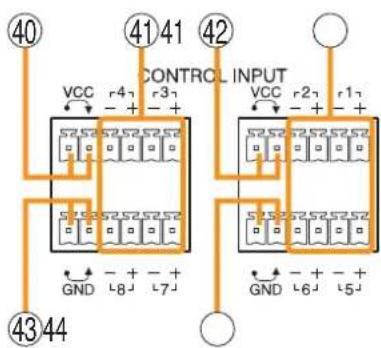
text_image
CONTROL INPUT VCC r4 r3 + - + GND + - + 40 41 42 VCC r2 r1 + - + 43 44 GND + - + 5 6 7 8 9 1040. Power Feed Jumper 2 [VCC]
The supplied removable terminal plug is equipped with a jumper.
When the jumper is attached, the circuits of control inputs 3, 4, 7, and 8 are powered from inside the SX-2100AO.
Removing the jumper disconnects this internal power supply and thus requires that power be supplied externally to the circuit. (See "Operation of Power Feed Jumper and Isolation Jumper" on the next page.)
41. Control Input Terminals [CONTROL INPUT 1 - 8]
Photo coupler inputs. A current of approximately 2 mA flows when shorted, and the voltage becomes under 40 V DC when opened. The input of 100 msec or greater is required to operate. These contact inputs can be isolated from the SX-2100AO unit by cutting power feed jumpers 1 (42) and 2 (40) and isolation jumpers 1 (44) and 2 (43). Each contact input when isolated is 40 V DC for maximum applied voltage and approximately 2 mA for the loop current. Since each terminal is equipped with a current limiter employing constant current circuitry, there is no need to limit the current on the external equipment side. The [-] terminals of 1, 2, 5, and 6 are common, while those of 3, 4, 7, and 8 are common.
Use the SX-2000 Setting Software to assign functions to these terminals. (See the separate Setting Software Instructions, "Event Settings.")
42. Power Feed Jumper 1 [VCC]
The supplied removable terminal plug is equipped with a jumper. When the jumper is attached, the circuits of control inputs 1, 2, 5, and 6 are powered from inside the SX-2100AO. Removing the jumper disconnects this internal power supply and thus requires that power be supplied externally to the circuit. (See "Operation of Power Feed Jumper and Isolation Jumper" shown below.)
43. Isolation Jumper 2 [GND]
The supplied removable terminal plug is equipped with a jumper. When the jumper is attached, the [-] terminals of control inputs 3, 4, 7, and 8 are connected to the internal power supply. Removing the jumper disconnects and isolates these [-] terminals from this unit. (See "Operation of Power Feed Jumper and Isolation Jumper" shown below.)
[Operation of Power Feed Jumper and Isolation Jumper]
![TOA D-921F - Isolation Jumper 2 [GND] - 1](/content/2026/06/1214100/images/d2a9b4c260edf888dfe4292d9fa16b60bd7063c0250aa49ac02d5c96a04669d3.jpg)
flowchart
graph TD
    A["Power feed jumper"] --> B["Photo coupler"]
    B --> C["Internal circuit"]
    D["VCC"] --> A
    E["Control input"] --> B
    F["Isolation jumper"] --> B
    G["GND"] --> B
    H["-"] --> B
    I["+"] --> B
44.Isolation Jumper 1 [GND]
The supplied removable terminal plug is equipped with a jumper.
When the jumper is attached, the [-] terminals of control inputs 1, 2, 5, and 6 are connected to the internal power supply.
Removing the jumper disconnects and isolates these [-] terminals from this unit. (See "Operation of Power Feed Jumper and Isolation Jumper" shown below.)
[Enlarged view of ④5-④9 on p. 29]
![TOA D-921F - 44.Isolation Jumper 1 [GND] - 1](/content/2026/06/1214100/images/898fabe553fe3f43f018dfbe7a90c820740852aa20985d06af7960f6bcf6ccc9.jpg)
text_image
45 46 47 48 N/C DS LINK 1 STANDBY ZONE7 LINK CI/CO 2 N/C ZONE8 LINK 49 4645. CI/CO Link Indicator [LINK] (Green)
Lights when the SX-2000CI or the SX-2000CO is connected.
46. Unused Terminals [N/C]
These terminals are not used.
47. DS Link Terminals [DS LINK 1/2]
Connect either terminal to the DS-SF Link terminal of the VX-2000DS.
48. Standby Amplifier Audio Output Terminal [PA LINK STANDBY]
Connect this terminal to the VP-200VX Power Amplifier Input Module built into a standby amplifier*.
* Use the VP-2064, VP-2122, VP-2241, or VP-2421.
49. CI/CO Link Terminal [CI/CO LINK]
Connect this terminal to the CI/CO Link Data Terminal of the SX-2000CI or SX-2000CO.
50. Audio Output Terminals
[PA LINK ZONE 1 - 8]
Connect these terminals to the VP-200VX Power Amplifier Input Modules used for zone output.
51. Local Audio Control Input Terminals [LOCAL AUDIO IN 1/IN 2]
Audio signals fed to these terminals are broadcast to only the zones that this unit covers. Each terminal is equipped with a control input, which allows local broadcasts to be made.
It is possible to isolate the control input from this unit by changing the internal jumper setting. (See p. 61 for details.)
Input "IN1" has a higher priority than Input "IN2." If the control input terminal of "IN1" is activated while broadcast is made through the "IN2," the broadcast is interrupted and changed to the broadcast through the "IN1."
The Local input has a lower priority than the BGM or general-purpose sound sources. Activating the emergency broadcasts to a part of zones where local broadcasts are currently in progress causes all local broadcasts to terminate.
52. Functional Earth Terminal [SIGNAL GND]
Hum noise may be generated when external equipment is connected to the unit. Connecting this terminal to the functional earth terminal of the external equipment may reduce the hum noise.
Note: This terminal is not for protective earth.
53. Standby Amplifier Input Terminal [STANDBY AMP]
Connect this terminal to the speaker output terminal of the standby amplifier ^*1 .
*1 Use the VP-2064, VP-2122, VP-2241, or VP-2421.
54. Speaker Connection Terminals [ZONE 1 - 8 SP]
Connect these terminals to speakers.
55. Amplifier Input Terminals [ZONE 1 - 8 AMP]
Connect these terminals to the speaker output terminals of the power amplifiers for zone output.
56. Analog Link Output Terminal [ANALOG LINK OUT]
Connect this terminal to the analog link input terminal of the SX-2000AI, SX-2100AI, SX-2000AO, or SX-2100AO.
![TOA D-921F - Analog Link Output Terminal [ANALOG LINK OUT] - 1](/content/2026/06/1214100/images/c2b1488b336eb0832fea3c8cca6d38807ee53cfeff371e9c304dc07391f50dce.jpg)
text_image
ANALOG LINK OUT IN STATUS LINK RESET LINK 1 2| Function LED On LED Off | ||
| 1. Not used | ||
| 2. OUT connection confirmation | Connected Unconnected | |
57. Analog Link Input Terminal [ANALOG LINK IN]
Connect this terminal to the analog link output terminal of the SX-2000SM, SX-2000AI, SX-2100AI, SX-2000AO, or SX-2100AO.
![TOA D-921F - Analog Link Input Terminal [ANALOG LINK IN] - 1](/content/2026/06/1214100/images/00570b3e3f9c4a04c192d8da3777dedf0afe48aa7d1295e791f43476846b33c8.jpg)
text_image
ANALOG LINK OUT IN STATUS LINK RESET LINK 3 4| Function LED On LED | Off | |
| 3. RESET input Resetting Normal | ||
| 4. Not used | ||
58. SX Link Terminals [SX LINK A/B]
Use switching hubs to connect between the SX link terminals of the SX-2000SM, SX-2000AI, SX-2100AI, SX-2000AO, and SX-2100AO.
Connect each of the SX Links A and B to the same switching hub ^2 , or to different switching hubs ^2 that have been cascade connected.
Notes
- Be sure to connect both terminals of A and B.
- After connection completion, press the Reset key to reactivate the SX-2100AO.
*2 Contact your TOA dealer for more information on switching hubs.

text_image
SX LINK B A IN USE LINK IN USE LINK 1 2 3 4| Function | LED On/Flashing | LED Off |
| 1. B operation in progress indication | Operating Not operating | |
| 2. B connection confirmation | Connected Unconnected | |
| 3. A operation in progress indication | Operating Not operating | |
| 4. A connection confirmation | Connected Unconnected | |
59. MAC Address
MAC address to be used for SX link connection.
1.6. SX-2000CI Control Input Unit
[Front]

text_image
TOA SK-8000 CI Protective cover ① ② ③ ④ CONTROL INPUT 1 2 3 4 5 6 7 8 9 10 11 12 13 14 20 21 22 23 24 25 26 27 R1X5H-F D5U4FF R4E-T CONTROL INPUT UNIT SKINNANInside of the protective cover
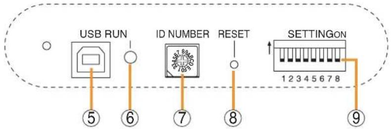
text_image
USB RUN ID NUMBER RESET SETTINGON 1 2 3 4 5 6 7 8 ⑤ ⑥ ⑦ ⑧ ⑨1. Control Input Indicators
[CONTROL INPUT 1 - 32] (Green)
Light when the corresponding control inputs are turned ON.
2. Power Indicator [POWER] (Blue)
Lights when the power is switched on.
3. CPU OFF Indicator [CPU OFF] (Red)
Lights while the general urgency all-call (CPU OFF state) is being made (p. 68).
4. FAULT Indicator [FAULT] (Yellow)
Lights while the general urgency all-call is being made (p. 68) or when communications to the SX-2000AO or SX-2100AO are interrupted for 5 seconds or more.
Flashes when a failure is detected in the system.
5. USB Port [USB]
This port is not used.
6. RUN Indicator [RUN] (Green)
Normally flashes continuously.
Goes off while the general urgency all-call is being made (p. 68).
7. ID Switch [ID NUMBER]
This switch is not used.
Always set to "0."
Note
This switch is set to "0" by default.
8. Reset Key [RESET]
Pressing this key resets the SX-2000CI.
9. DIP Switch [SETTING]
These switches are not used.
Note
Switches 1 - 8 are set to the OFF position by default.
[Rear]
![TOA D-921F - [Rear] - 1](/content/2026/06/1214100/images/06a0cc508445102893852145aaf340967b9eb86f10ff8453ee2b6a5eee4a4e68.jpg)
text_image
⑩ ⑪ ⑫ 14 15 1613 DC POWER IN INVOICE NAME DC OUT MAX. FLA C:\WINDOWS\2019\2020\NFS\2021\2022\NFS\2023\2024\NFS\2025\2026\NFS\2027\2028\NFS\2029\2030\NFS\2031\2032\NFS\2033\2034\NFS\2035\2036\NFS\2037\2038\NFS\2039\2040\NFS\2041\2042\NFS\2043\2044\NFS\2045\2046\NFS\2047\2048\NFS\2049\2050\NFS\2051\2052\NFS\2053\2054\NFS\2055\2056\NFS\2057\2058\NFS\2059\2060\NFS\2061\2062\NFS\2063\2064\NFS\2065\2066\NFS\2067\2068\NFS\2069\2070\NFS\2071\2072\NFS\2073\2074\NFS\2075\2076\NFS\2077\2078\NFS\2079\2080 CCKO LINK THROUGH DATA10. Functional Earth Terminal [SIGNAL GND]
Hum noise may be generated when external equipment is connected to the unit. Connecting this terminal to the functional earth terminal of the external equipment may reduce the hum noise.
Note: This terminal is not for protective earth.
11. DC Power Input Terminal [DC POWER IN]
Connect an optional DC power supply unit to this terminal. Select the DC power supply source with consideration given to the current power consumption of the system the SX-2000CI is to be connected to. When not using a redundant power system*, connect the [+] terminal of input A to the [+] terminal of input B, and the [-] terminal of input A to the [-] terminal of input B. (Refer to the Instruction Manual attached to the VX-2000DS.)
* A method of connecting separate power sources to each power input or connecting the commercial power supply and backup power supply separately to each power input to prevent the system from going down when a cable is broken or power fails.
12. 24 V DC Output Terminal [DC 24 V OUT]
This terminal supplies 24 V DC, max. 100 mA to connected external equipment.
13. Control Input Terminals [CONTROL INPUT 1 - 32]
Photo coupler inputs. A current of approximately 2 mA flows when shorted, and the voltage becomes approximately 24 V DC when opened. Functions can be assigned to these terminals using the SX-2000 Setting Software. (See the separate Setting Software Instructions, "Event Settings.")
14. CI/CO Link Through Switch [ON/OFF]
Set to ON when using the CI/CO Link Through Terminal (15). (Factory-preset: OFF)
15. CI/CO Link Through Terminal [CI/CO LINK THROUGH]
Connect this terminal to the CI/CO Link Data Terminal of the SX-2000CO.
Refer to the table below for the indicators' functions and status.
16. CI/CO Link Data Terminal [CI/CO LINK DATA]
Connect this terminal to the CI/CO Link Terminal of the SX-2000AO or SX-2100AO, or CI/CO Link Through Terminal of the SX-2000CO.
Refer to the table below for the indicators' functions and status.
[Indicators' functions and status of the CI/CO Link Through/Data terminals]
![TOA D-921F - [Indicators' functions and status of the CI/CO Link Through/Data terminals] - 1](/content/2026/06/1214100/images/7f3b2351c275875a74940a9d3337d9b0fcb0bfa809c32bce6906ccb866513fef.jpg)
text_image
CI/CO LINK THROUGH DATA 1 2 3 4| Functions LED On or Flashing (green) LED Off LED On (orange) | |||
| 1. CI/CO LINK status Communication start | Communication stop | —— | |
| 2. —— | —— | —— | —— |
| 3. CI/CO LINK status Communication start | Communication stop | —— | |
| 4. CI/CO LINK connection confirmation | —— | Unconnected | Connected |
1.7. SX-2000CO Control Output Unit
[Front]
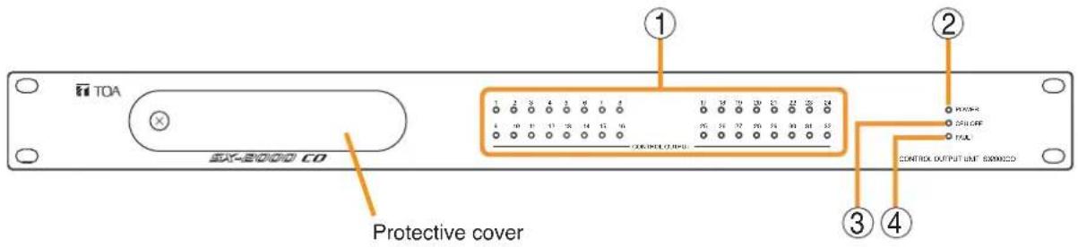
text_image
TOA SXT-2000 CO Protective cover ① ② ③ ④ CONTROL OUTPUT UNIT 8300000Inside of the protective cover

text_image
USB RUN ID NUMBER RESET SETTINGON 1 2 3 4 5 6 7 8 ⑤ ⑥ ⑦ ⑧ ⑨1. Control Output Indicators
[CONTROL OUTPUT 1 - 32] (Green)
Light when the corresponding control outputs are turned ON.
All indicators are factory-preset to go off because all control outputs are turned off when the general urgency all-call is made. By changing the internal DIP switch settings for the desired control outputs, the corresponding outputs can be turned ON, making the indicators light up when the general urgency all-call is made. (For details, see p. 62.)
2. Power Indicator [POWER] (Blue)
Lights when the power is switched on.
3. CPU OFF Indicator [CPU OFF] (Red)
Lights while the general urgency all-call (CPU OFF state) is being made (p. 68).
4. FAULT Indicator [FAULT] (Yellow)
Lights while general urgency all-call is being made (p. 68) or when communications to the SX-2000AO or SX-2100AO are interrupted for 5 seconds or more. Flashes when a failure is detected in the system.
5. USB Port [USB]
This port is not used.
6. RUN Indicator [RUN] (Green)
Normally flashes continuously.
Goes off while the general urgency all-call is being made (p. 68).
7. ID Switch [ID NUMBER]
This switch is not used.
Always set to "1."
Note
This switch is set to "1" by default.
8. Reset Key [RESET]
Pressing this key resets the SX-2000CO.
9. DIP Switch [SETTING]
These switches are not used.
Note
Switches 1 - 8 are set to the OFF position by default.
[Rear]

text_image
⑩ ⑪ DC POWER IN W2001-400V ① ⑭ ⑮ ⑯ ⑰ ⑱ ⑲ ⑳ ⑴ ⑫ ⑬ ⑭ ⑮ ⑯ ⑰ ⑱ ⑲ ⑳ ⑮ ⑯ ⑰ ⑱ ⑲ ⑳ ⑮ ⑯ ⑰ ⑱ ⑲ ⑳ ⑮ ⑯ ⑰ ⑱ ⑲ ⑳ ⑮ ⑯ ⑰ ⑱ ⑲ ⑳ ⑮ ⑯ ⑰ ⑱ ⑲ ⑳ ⑮ ⑯ ⑰10. Functional Earth Terminal [SIGNAL GND]
Hum noise may be generated when external equipment is connected to the unit.
Connecting this terminal to the functional earth terminal of the external equipment may reduce the hum noise.
Note
This terminal is not for protective earth.
11. DC Power Input Terminal [DC POWER IN]
Connect an optional DC power supply unit to this terminal.
Select the DC power supply source with consideration given to the current power consumption of the system the SX-2000CO is to be connected to. When not using a redundant power system*, connect the [+] terminal of input A to the [+] terminal of input B, and the [-] terminal of input A to the [-] terminal of input B. (Refer to the Instruction Manual attached to the VX-2000DS.)
* A method of connecting separate power sources to each power input or connecting the commercial power supply and backup power supply separately to each power input to prevent the system from going down when a cable is broken or power fails.
12. Control Output Terminals
[CONTROL OUTPUT 1 - 32]
Relay make contact outputs. Each contact capacity is rated at 40 V DC for withstand voltage, and 2 mA – 300 mA for control current. These terminals are controlled by the SX-2000 Setting Software. (See the separate Setting Software Instructions, "Pattern Settings.")
13. CI/CO Link Through Switch [ON/OFF]
Set to ON when using the CI/CO Link Through Terminal (14). (Factory-preset: OFF)
14. CI/CO Link Through Terminal [CI/CO LINK THROUGH]
Connect this terminal to the CI/CO Link Data Terminal of the SX-2000CI.
Refer to the table below for the indicators' functions and status.
15. CI/CO Link Data Terminal [CI/CO LINK DATA]
Connect this terminal to the CI/CO Link Terminal of the SX-2000AO or SX-2100AO, or CI/CO Link Through Terminal of the SX-2000CI.
Refer to the table below for the indicators' functions and status.
[Indicators' functions and status of the CI/CO Link Through/Data terminals]
![TOA D-921F - [Indicators' functions and status of the CI/CO Link Through/Data terminals] - 1](/content/2026/06/1214100/images/25e46700595abe0058819fe2b5825dfe9656a2bf9c2ca94daf8c783c0b5363ec.jpg)
text_image
CI/CO LINK THROUGH DATA 1 2 3 4| Functions LED On or Flashing (green) LED Off | LED On (orange) | ||
| 1. CI/CO LINK status Communication start | Communication stop | —— | |
| 2. —— | —— | —— | —— |
| 3. CI/CO LINK status Communication start | Communication stop | —— | |
| 4. CI/CO LINK connection confirmation | —— | Unconnected | Connected |
1.8. RM-200SF Fireman's Microphone
[Top]

text_image
TOA RM-200SF RIMKINS MICROPHONE MIC SP CPU CPF OK [Hand-held microphone] 1 2 3 4 5 6 7 8 9 10 11 12 13 14 15 16 17 181. Power Indicator (Green)
Lights when the power is turned on.
2. Emergency Key
Assign emergency activation function to this key using the SX-2000 Setting Software. Lights when the SX-2000 system is in an emergency condition.
3. Monitor Speaker
Not used.
4. Monitor Speaker Volume Control [SP]
Not used.
5. Microphone Volume Control [MIC]
Adjusts the input sensitivity of the Hand-held Microphone.
6. Microphone Hanger
Used to hold the unit's Hand-held Microphone.
7. CPU Switch [CPU ON/OFF]
Normally set to ON. (Factory-preset: ON) Setting this switch to OFF in combination with the DIP switch setting (20) on the bottom surface allows the general urgency all-call to be made using a hand-held microphone by way of analog transmission not via the CPU control.
8. Indication Label Insert Slot
The label can be printed using the SX-2000 Setting Software. (See the separate Setting Software Instructions, "Printing Labels for Remote Microphones.")
9. Failure Indicator (Yellow/Red)
Flashes yellow if some problem within the system is detected.
This indicator will light yellow if the signal to the SX-2000AI or SX-2100AI to which the RM-200SF is connected is interrupted for 5 seconds or more.
Lights red when the unit is placed in reset state by pressing the Reset Switch (11).
10. CPU Indicator (Red)
Lights red when any one of the CPU switches on the RM-200SFs connected within the system is set to OFF or when the general urgency all-call is being made by any one of the RM-200SAs connected within the system.
11. Reset Switch
Used to reactivate the RM-200SF unit. Holding down both this switch and the R3 key of the Function keys (14) for 2 seconds or more causes the Failure Indicator (9) to light red, placing the RM-200SF in reset state.
12. Status Indicators (Red/Yellow/Green)
Light, flash, or go off depending on the current operation state of function keys, failure state or emergency state. (See the separate Operating Instructions, "RM-200SF Fireman's Microphone" and "Operation.")
13. Selection Indicators (Green)
Light or go off depending on the current operation state of function keys. (See the separate Operating Instructions, "RM-200SF Fireman's Microphone" and "Operation.")
14. Function Keys (R1 - R3)
Positioned in top-down order (R1, R2, R3). Pressing a specific function key executes the function that has been assigned to that key by the SX-2000 Setting Software.
Assignment of functions to specific keys is done using the SX-2000 Setting Software. (See the separate Setting Software Instructions, "Event Settings.")
15. Microphone Indicator (Green)
Lights or goes off depending on the current operation state of the Talk key.
16. Broadcast Status Indicator (Yellow/Green)
Lights, flashes, or goes off depending on the current operation state of the Talk key.
17. Talk Key
Press this key to broadcast a voice announcement. It must be pressed continuously for the duration of the broadcast.
18. Microphone
Used for voice announcements.
[Side]

text_image
19 EXTENSION19. RM-210 Connection Terminal [EXTENSION]
Connect the RM-210 Remote Microphone Extension unit to this terminal. (See p. 79 and p. 82.)
[Bottom]
![TOA D-921F - [Bottom] - 1](/content/2026/06/1214100/images/b84bfe354a6851d7268f76bfe831a64f1fbcd096e17c8d0f46166c80065f3df5.jpg)
text_image
20 21 22 CIP START LED CIP UNIT D STANDARD METERING RUMBER SETTING SETTING HOLD CAP. RUN[Wall mount bracket unit (Accessory)]
![TOA D-921F - [Wall mount bracket unit (Accessory)] - 1](/content/2026/06/1214100/images/c246293244cd9c966242583ad973d3e6a241ade9da2e95119e2d7e3d7575c42e.jpg)
- Switches 1 – 3 [UNIT ID] Set the RM-200SF's device number (ID number). (See p. 64.)
- Switch 4 [COMMUNICATION] Sets the RM communication function. (See p. 69.)
- Switch 5 [LEVEL METER] Changes a broadcast status indicator (12) into an output signal level indicator. (See p. 66.)
- Switch 6 [CPU OFF] Sets whether the CPU OFF function (general urgency all-call) is enabled or disabled. (See p. 68.)
- Switch 7 Not used. Normally set to OFF.
- Switch 8 [TERMINATION] Sets the termination of the RM communication line (Control communication lines between the SX-2000 system and the RM-200SF). Normally set to ON.
Note
By default, DIP switches 1 - 5 and 7 are set to OFF, and DIP switches 6 and 8 to ON.
21. USB Terminal
Not used.
22. Extension Connector
Connect this connector to the extension connector (23) of the Wall Mount Bracket Unit (accessory). (See p. 78.)
23. Extension Connector
Connect the cable extending from the RM-200SF to this connector. (See p. 78.)
24. Screw Terminal Block
• Audio Monitor Line [MONITOR IN]
Connect the audio monitor input line from the SX-2000 system to the RM-200SF.
- RM Communication Line [DATA]
Connect the control communication line between the SX-2000 system and the RM-200SF.
• Audio Output Line [AUDIO OUT]
Connect the audio signal output line from the RM-200SF to the SX-2000 system.
- DC Power Input [DC IN 24 V]
Used to supply DC power from the SX-2000 system to the RM-200SF.
- Shield [SHIELD]
Used for the control line through which the SX-2000 system confirms the RM-200SF's connection.
Be sure to connect at least one of two terminals to the SX-2000 system.
1.9. RM-200SA Remote Microphone
[Top]

text_image
① ② 4 6 7 9 ③ ⑤ ⑧ ⑥ ⑦ ⑧ TOA RM-200SA 11 12 13 101. Microphone
Used for voice announcements.
2. Power Indicator (Green)
Lights when the power is turned on.
3. Failure Indicator (Yellow/Red)
Flashes yellow if some problem within the system is detected.
This indicator will light yellow if the signal to the SX-2000AI or SX-2100AI to which the RM-200SA is connected is interrupted for 5 seconds or more. This indicator will light red while the general urgency all-call is being made (p. 68) or the RM-200SA is in the reset process.
4. Emergency Indicator (Red)
Lights when the SX-2000 system is in an emergency condition.
5. Emergency/General Urgency All-call Key (Covered)
When the Emergency Broadcast Pattern Start function has been assigned to this key by the SX-2000 Setting Software, pressing it activates the emergency broadcast from the SX-2000 system. Independently of settings made by the SX-2000 Setting Software, holding down this key for 4 seconds or more in combination with DIP switch (14) setting causes the CPU to be bypassed, enabling the general urgency all-call to be made by way of analog transmissions. (See p. 68.)
6. Indication Label Insert Slots
Labels can be printed using the SX-2000 Setting Software. (See the separate Setting Software Instructions, "Printing Labels for Remote Microphones.")
7. Status Indicators (Red/Yellow/Green)
Light, flash, or go off depending on the current operation state of function keys, failure state or emergency state. (See the separate Operating Instructions, "Remote Microphone RM-200SA, Remote Microphone Extension RM-210" and "Operation.")
8. Selection Indicators (Green)
Light or go off depending on the current operation state of function keys.
(See the separate Operating Instructions, "Remote Microphone RM-200SA, Remote Microphone Extension RM-210" and "Operation.")
9. Function Keys (R1 - R10)
Positioned in top-down order (R1, R2 ... R10). Pressing a specific function key executes the function that has been assigned to that key by the SX-2000 Setting Software.
Assignment of functions to specific keys is done using the SX-2000 Setting Software. (See the separate Setting Software Instructions, "Event Settings.")
10. Talk Key
Press this key to broadcast a voice announcement. If the Talk key is set to "PTT" ("press-to-talk") mode, then it must be pressed continuously for the duration of the broadcast.
If the Talk key is set to "Lock" mode, then it must be pressed once to turn the microphone on at the beginning of a broadcast, then pressed again to turn the microphone off once the broadcast is finished.
The microphone can also be set to sound a chime at the beginning and/or end of each broadcast.
The Talk key mode ("PTT" or "Lock") and the chime function are set using the SX-2000 Setting Software. The RM-200SA of which "Type" is set to "General/Emergency" on the SX-2000 Setting software is fixed to "PTT" mode for the Talk key with no chime activation. (See the separate Setting Software Instructions, "System Settings.")
11. Function Keys (L1 - L3)
Positioned in top-down order (L1, L2, L3).
These keys operate in the same manner as the Function keys (R1 - R3) (No. 9).
12. Broadcast Status Indicator
(Yellow/Green)
Lights, flashes, or goes off depending on the current operation state of the Talk key.
13. Microphone Indicator (Green)
Lights or goes off depending on the current operation state of the Talk key.
Flashes while the chime is being activated.
[Side]

text_image
14 15 Extension14. DIP Switch
Used for setting the RM-200SA unit.
- Switches 1 – 3 Sets the RM-200SA's device number (ID number). (See p. 64.)
- Switch 4 Changes a broadcast status indicator (12) into an output signal level indicator. (See p. 66.)
- Switch 5 Sets whether the CPU OFF function (general urgency all-call) is enabled or disabled. (See p. 68.)
- Switch 6 Sets the RM communication function. (See p. 69.)
Note
By default, DIP switches 1 – 4 and 6 are set to OFF and DIP switch 5 to ON.
15. RM-210 Connection Terminal [EXTENSION]
Directly connect the RM-210 Remote Microphone Extension unit to this terminal.
(See p. 79 and p. 82.)
[Rear]
![TOA D-921F - [Rear] - 1](/content/2026/06/1214100/images/bdfecf1fc497575ad08c82d30f661cb4620cb24b8397c013604af8a824480a5e.jpg)
text_image
DC POWER IN 24V USB LINK RM INK SP MC EXTERNAL MC IN ⑯⑯⑯⑰⑱⑲⑳⑳⑺⑳⑭⑮⑯⑰⑱⑲⑳⑴⑵⑶⑷⑧⑨⑩⑪⑫⑬⑭⑮⑯⑰⑱⑲⑳⑴⑵⑶⑷⑸⑨⑩⑪⑫⑬⑭⑮⑯⑰⑱⑲⑳⑴⑵⑶⑷⑸⑨⑩⑪⑫⑬⑭⑮⑯⑰⑱⑲⑳⑴ ⑤ ⑥ ⑦ ⑧ ⑨ ⑩ ㉑ ㉒ ㉓ ㉔ ㉕ ㉖ ㉗ ㉘ ㉙ ㉚ ㉛ ㉜ ㉝ ㉞ ㉟ ㉟ ㉟ ㉟ ㉟ ㉟ ㉟ ㉟ ㉟ ㉟ ㉟ ㉟ ㉟ ㉟ ㉟ ㉟ ㉟ ㉟ ㉟ ㉟ ㉟ ㉟ ㉟ ㉟ ㉟ ㉟ ㉟ ㉟ ㉟ ㉟ ㉟ ㉟ ㉟ ㉟16. Power Input Terminal [DC POWER IN]
Connect an optional AD-246 AC adapter to this terminal when extending cable length. Power is usually supplied to the RM-200SA and RM-210 from the SX-200RM Remote Microphone Interface Module. (See p. 103.)
17. USB Terminal [USB]
Not used.
18. RM Link Terminal [RM LINK]
Used to connect an SX-200RM Remote Microphone Interface Module via a STP Category 5 cable.
19. Speaker Volume Control [SP]
Adjusts the volume of the built-in speaker.
20. Microphone Volume Control [MIC]
Adjusts the volume of the microphone (1) and the external microphone connected via the external microphone input terminal (21).
21. External Microphone Input Terminal [EXTERNAL MIC IN]
Connect an optional external microphone ^*1 to this terminal.
Jumper settings on the circuit board must be changed depending on the input sources. (See p. 70.)
Specifications: -40 dB ^*2 , 2.2 kΩ, unbalanced, mini-jack, and phantom power.
*1 The WH-4000A, YP-M101, or YP-M301 can be used for the external microphone.
^*2 0 dB = 1 V
1.10. RM-210 Remote Microphone Extension
Note
Up to 5 RM-210 Remote Microphone Extensions can be connected to each RM-200SF Fireman's Microphone.
Up to 4 RM-210 Remote Microphone Extensions can be connected to each RM-200SA Remote Microphone.
[Top]
![TOA D-921F - [Top] - 1](/content/2026/06/1214100/images/8383637505439e8aa3ab090af0c8dfa199b873b4a4b07db24aeff7ee86b79a4f.jpg)
text_image
TOA RM-210 ① ② ③ ④1. Indication Label Insert Slot
The label can be printed using the SX-2000 Setting Software. (See the separate Setting Software Instructions, "Printing Labels for Remote Microphones.")
2. Status Indicators (Red/Yellow/Green)
Light, flash, or go off depending on the current operation state of function keys.
3. Selection Indicators (Green)
Light or go off depending on the current operation state of function keys
4. Function Keys (1 - 10)
Positioned in top-down order (1, 2 ... 10). Pressing a specific function key executes the function that has been assigned to that key by the SX-2000 Setting Software.
Assignment of functions to specific keys is done using the SX-2000 Setting Software. (See the separate Setting Software Instructions, "RM Function Key Settings.")
[Side]
![TOA D-921F - [Side] - 1](/content/2026/06/1214100/images/b08d8d11e4a3bdaa2d3769a4bfc2d18db454d4fd46482842118332f5b3fdb1ae.jpg)
text_image
DT-100k ⑤5. RM Connection Terminal [EXTENSION]
Connect the RM-200SF, RM-200SA, or other RM-210 to this terminal. (See p. 79 and p. 82.)
Note
Another same terminal is on the other side.
1.11. RM-200RJ Terminal Unit
[Front]

text_image
TOA MONITOR H ① C ② AUDIO H ④ C ⑤ RM LINK DATA + ③ - ⑥ DC 24V + ⑦ - ⑧ SHIELD ON OFF DC MONITOR TERMINAL UNIT RM-200RJ1. RM Link Terminal [RM LINK]
Connect to the RM Link terminal of the RM-200SA or SX-200RM.
2. Power Monitor Switch [ON/OFF]
Set to ON to enable the Power Monitor Indicator. (Factory-preset: ON)
3. Power Monitor Indicator (Green)
Lights if the source voltage of the DC power input exceeds the minimum operating voltage of the RM-200SA when the Power Monitor Switch is set to ON.
4. Screw Terminal Block
The Screw terminal block and RM link terminal are internally connected in parallel. Numbers ① through ⑧ndicated beside each terminal correspond to the pin numbers of the RJ45 connector to be connected to the RM link terminal (1).
• Audio monitor terminals [MONITOR H/C]
Connect the audio monitor line from the SX-2000 system to the RM-200SA.
- Audio output terminals [AUDIO H/C]
Connect the audio output line from the RM-200SA to the SX-2000.
- RM communication terminals [DATA +/-] Connect the control communication line between the SX-2000 system and the RM-200SA.
- DC power input terminals [DC 24 V +/-]
Used to supply DC power from the SX-2000 system to the RM-200SA.
- Shield terminals [SHIELD]
Connect the shield wires for noise reduction or for system control.
Be sure to connect at least one shield wire.
1.12. Optional Modules
The following modules can be used in the input module slots on the SX-2000AI's and SX-2100AI's rear panels:
SX-200RM Remote Microphone Interface Module
D-921E, D-921F, D-922E and D-922F Microphone/Line Input Modules
D-936R Stereo Input Module
Note
All of the inserted modules cannot be recognized correctly when any module other than listed above is inserted into the SX-2000AI's or SX-2100AI's module slots.
1.12.1. SX-200RM Remote Microphone Interface Module
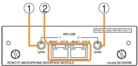
text_image
① ② ① RM LINK 1 2 LINKACT STATUS LINKACT STATUS GAIN FDI S-2000 SERIES ONLY GAIN REMOTE MICROPHONE INTERFACE MODULE model SX-200RM1. Gain Control Knobs [GAIN]
Increase the audio level of the RM-200SF or RM-200SA Remote Microphone by up to 12 dB.
2. RM Link Terminals [RM LINK 1/2]
Used to connect the RM-200SF or RM-200SA Remote Microphones. Each terminal can supply up to 1 A of power to the connected RM-200SF or RM-200SA/210.
![TOA D-921F - RM Link Terminals [RM LINK 1/2] - 1](/content/2026/06/1214100/images/9ba296273eecbbb7151ad3eb5c9db098e75496849413b2e6e563dbf025fb495d.jpg)
text_image
RM LINK 1 2 LINK/ACT STATUS LINK/ACT STATUS 1 2 3 4| Function LED On or Flashing (Green) LED Off LED On (Orange) | |||
| 1. RM1 connection confirmation | Connected | Unconnected | — |
| 2. RM1 status | Communication start | Communication stop | Control start |
| 3. RM2 connection confirmation | Connected | Unconnected | — |
| 4. RM2 status | Communication start | Communication stop | Control start |
Note
The terminal with the RM1 or RM2 status LED lit orange is the one assigned by the SX-2000 Setting Software. Connect the RM-200SF or RM-200SA to that terminal.
1.12.2. D-921E Microphone/Line Input Module
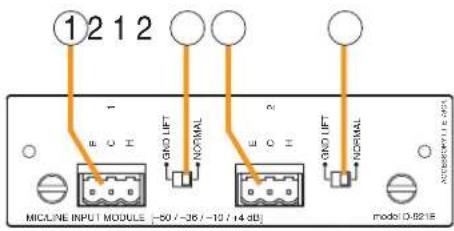
text_image
①2 1 2 E O E GNO LIFT NORMAL E O H GNO LIFT NORMAL MICLINE INPUT MODULE -50 / -35 / -12 / 14 dB mode D-82181. Monaural Input Terminals [1, 2]
Electronically-balanced, removable terminal blocks. (H: Hot; C: Cold; E: Ground) Input sensitivity (-50/-36/-10/+4 dB) and phantom power (+12 V) ON/OFF can be set by the SX-2000 Setting Software.
Note
Be sure to use the supplied removable terminal plugs (3P) for connection.
2. Ground Lift Switches [GND LIFT/NORMAL]
Hum noise may be generated due to ground loops created when the SX-2000 system is connected to other equipment. Setting the switch to the GND LIFT position cuts the ground loop.
1.12.3. D-921F Microphone/Line Input Module

text_image
①212 CND LIFT NORMAL N CND LIFT NORMAL E H C ACCESSWITLE BLOCK MICLINE INPUT MODULE (-50 / -36 / -10 / 14 dB) model D-921F1. Monaural Input Terminals [1, 2] (XLR-3-31 equivalent)
Electronically-balanced input terminals. (Pin 1: Ground; Pin 2: Hot; Pin 3: Cold) Use XLR-3-12C or equivalent for connection. Input sensitivity (-50/-36/-10/+4 dB) and phantom power (+12 V) ON/OFF can be set by the SX-2000 Setting Software.
3: Cold
![TOA D-921F - Monaural Input Terminals [1, 2] (XLR-3-31 equivalent) - 1](/content/2026/06/1214100/images/4fe049fe3966bc7ba550a93f99e021d065c250978f5742005673b410c3898653.jpg)
2. Ground Lift Switches [GND LIFT/NORMAL]
Hum noise may be generated due to ground loops created when the SX-2000 system is connected to other equipment. Setting the switch to the GND LIFT position cuts the ground loop.
1.12.4. D-922E Microphone/Line Input Module
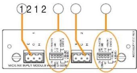
text_image
①212 MIC/LINE INPUT MODULE P208 D-822E1. Monaural Input Terminals [1, 2]
Electronically-balanced, removable terminal blocks. (H: Hot; C: Cold; E: Ground)
Note
Be sure to use the supplied removable terminal plugs (3P) for connection.
2. Input Sensitivity Switches [PHANTOM, GND LIFT, MIC/LINE]
4-pole switches. Enable phantom power (+12V; ON/OFF, enabled only when set to the MIC position), ground lift and input sensitivity.
Input sensitivity: -36 or -50 dB (MIC mode) / -10 or +4 dB (LINE mode)
![TOA D-921F - Input Sensitivity Switches [PHANTOM, GND LIFT, MIC/LINE] - 1](/content/2026/06/1214100/images/b47cf789a588934afb0b6b576b938e086e42f922b4bcd60461b59c1d1da68f86.jpg)
text_image
ON NORMAL MIC OFF : PHANTOM LIFT : GND LINE + 4 dB (LINE) -36 dB (MIC) -10 dB (LINE) -50 dB (MIC)1.12.5. D-922F Microphone/Line Input Module
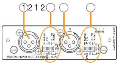
text_image
①212 MIGLINE INPUT MODULE module D-822F ② ③ ④ ⑤ ⑥ ⑦ ⑧ ⑨ ⑩ ⑪ ⑫ ⑬ ⑭ ⑮ ⑯ ⑰ ⑱ ⑲ ⑳ ⑴ ⑵ ⑶ ⑷ ⑸ ⑹ ⑺ ⑳ ⑪ ⑫ ⑬ ⑭ ⑮ ⑯ ⑰ ⑱ ⑲ ⑳ ⑴ ⑤ ⑥ ⑦ ⑧ ⑨ ⑩ ⑪ ⑫ ⑬ ⑭ ⑮ ⑯ ⑰ ⑱ ⑲ ⑳ ㉑ ㉒ ㉓ ㉔ ㉕ ㉖ ㉗ ㉘ ㉙ ㉚ ㉛ ㉜ ㉝ ㉞ ㉟ ㉳ ㉟ ㉟A ㉟B ㉟C ㉟D ㉟E ㉟F1. Monaural Input Terminals [1, 2] (XLR-3-31 equivalent)
Electronically-balanced input terminals. (Pin 1: Ground; Pin 2: Hot; Pin 3: Cold) Use XLR-3-12C or equivalent for connection.
![TOA D-921F - Monaural Input Terminals [1, 2] (XLR-3-31 equivalent) - 1](/content/2026/06/1214100/images/080ee028d2cfa41a6f5572bc8e822a8151e837b6d7b61016a044fa165941c032.jpg)
2. Input Sensitivity Switches [PHANTOM, GND LIFT, MIC/LINE]
4-pole switches. Enable phantom power (+12 V; ON/OFF, enabled only when set to the MIC position), ground lift and input sensitivity. Input sensitivity: -36 or -50 dB (MIC mode) / -10 or +4 dB (LINE mode)
![TOA D-921F - Input Sensitivity Switches [PHANTOM, GND LIFT, MIC/LINE] - 1](/content/2026/06/1214100/images/679aa5430526769a0040d075aa2487795de1f57189602fba70723f270bcf0b44.jpg)
text_image
ON NORMAL MIC OFF : PHANTOM LIFT : GND LINE + 4 dB (LINE) -36 dB (MIC) -10 dB (LINE) -50 dB (MIC)1.12.6. D-936R Stereo Input Module

text_image
1 2 model D-935RST/REO SELECT INPUT MODULE [-10 dB]Notes
- This module can only be used in the SX-2000 system for monaural input.
- Make sure that the channels indicated on the module differ from those set for the SX-2000 system.
1. Monaural Input Terminal 1 [1L/2L/3L/4L]
Unbalanced, RCA jack input terminals.
Input signal level: -10 dB
2. Monaural Input Terminal 2 [1R/2R/3R/4R]
Unbalanced, RCA jack input terminals.
Input signal level: -10 dB
1.13. VP-2064, VP-2122, VP-2241, and VP-2421 Power Amplifiers
Four different configurations of power amplifiers can be used in the SX-2000 system: 60 W x 4 channels, 120 W x 2 channels, 240 W x1 channel, and 420 W x 1 channel versions. Mount a VP-200VX Power Amplifier Input module for each channel used.
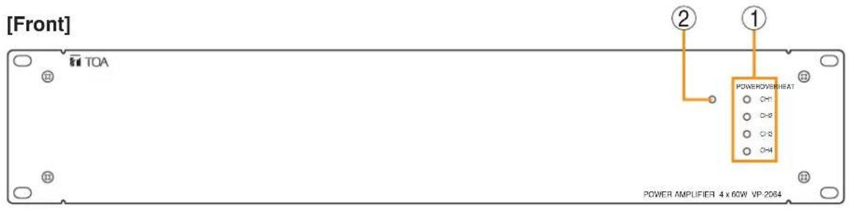
text_image
[Front] TOA POWEROVERHEAT C-1 C-2 C-3 C-4 ② ① POWER AMPLIFIER 4 x 60W VP 2064[Rear]

text_image
DC POWER IN 25 V 电源 + - PA OUT (SP LINE) CH43 CH33 CH21 CH11 ③ ④ ⑤ ⑥1. Channel Power Indicators [POWER]
Only the indicator for the input module-mounted channel lights green when the power is supplied.
- Off: VP-200VX not installed
• Lights green: In-use status - Lights red: Standby status or DC fuse blowout
2. Overheat Indicator [OVERHEAT]
If the internals of the power amplifier overheat, this indicator lights yellow and the power amplifier's operation is stopped.
3. Functional Earth Terminal
Hum noise may be generated when external equipment is connected to the unit. Connecting this terminal to the functional earth terminal of the external equipment may reduce the hum noise.
Note: This terminal is not for protective earth.
4. DC power Input Terminal [DC POWER IN]
Connects to the VX-2000DS Emergency Power Supply's DC POWER OUT terminal.
5. Output Terminals [PA OUT (SP LINE)]
Connect to the amplifier input terminal of the SX-2100AO Audio Output Unit.
The speaker line output voltage can be changed with an internal modification.
For the modification procedure, see p. 87.
6. Module Slots
Insert the VP-200VX Power Amplifier Input modules into these slots.
1.14. VP-200VX Power Amplifier Input Module
Insert this module into the Power Amplifier's Input module slot when in use.
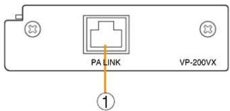
text_image
PA LINK VP-200VX ①1. Input Connector [PA LINK]
This RJ45 connector connects to the SX-2100AO's PA LINK (ZONE 1 – 8, STANDBY) connector. Output audio signals are transmitted to the power amplifier, and the power amplifier's audio monitor signals are returned to the module. It is also possible to retrieve data regarding power amplifier overheating status and blown DC fuses.
2. INSTALLATION
2.1. SX-2000SM
2.1.1. System reset enable/disable settings (DIP switch 3 operation)
The entire system can be reactivated by pressing the SX-2000SM's reset key. It is also possible to enable the entire system to restart through the operation of System Reset button on the SX-2000 Setting software.
Use the SX-2000SM's DIP switch 3 to enable or disable the system reset function with the SX-2000 Setting software.
Note
For the system reset method with the SX-2000 Setting software, see the separate Setting Software Instructions, "Resetting the System.")
Step 1. Remove the protective cover on the SX-2000SM's front panel by unscrewing it with a Phillips screwdriver.

flowchart
graph LR
    A["Protective cover"] --> B["Inside of the protective cover"]
    B --> C["RESET"]
    B --> D["USB"]
    B --> E["ACCESS"]
    B --> F["CF CARD"]
    B --> G["ON"]
    B --> H["SETTING"]
    H --> I["DIP switchReset key"]
Step 2. Perform DIP switch setting.
2-1. When enabling system reset
Set DIP switch 3 to OFF.
Operation with the System Reset button on the SX-2000 Setting software is enabled.
2-2. When disabling system reset
Set DIP switch 3 to ON.
Operation with the System Reset button on the SX-2000 Setting software is disabled.
Note: DIP switch 3 is set to the OFF position by default.
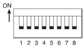
text_image
ON 1 2 3 4 5 6 7 8
text_image
ON 1 2 3 4 5 6 7 8Step 3. Replace the protective cover.
2.1.2. Failure reset operation method settings (DIP switch 4 operation)
One of the following 2 modes can be selected with the SX-2000SM's DIP switch 4 to determine the operation method of the SX-2000SM's front-mounted FAULT RESET key and rear-mounted RES terminals of the Date input terminals.
One touch mode: Pressing the key once or shorting the terminals once executes the failure reset.
Accidental operation prevention mode: Performing special operation executes the failure reset.
Note
For the detailed description of the operation method, see the separate Operating Instructions, "Detecting Fault."
Step 1. Remove the protective cover on the SX-2000SM's front panel by unscrewing it with a Phillips screwdriver.
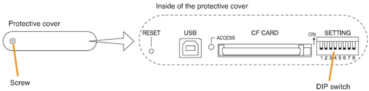
text_image
Protective cover Inside of the protective cover Screw RESET USB ACCESS CF CARD ON SETTING 1 2 3 4 5 6 7 8 DIP switchNote: DIP switch 4 is set to the OFF position by default.
Step 2. Perform DIP switch setting.
2-1. When selecting one touch mode Set DIP switch 4 to OFF.
2-2. When selecting accidental operation prevention mode Set DIP switch 4 to ON.
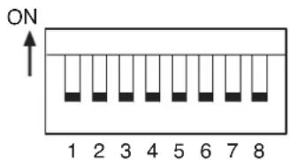
text_image
ON 1 2 3 4 5 6 7 8
text_image
ON 1 2 3 4 5 6 7 8Step 3. Replace the protective cover.
2.2. SX-2000AI and SX-2100AI
2.2.1. Module installation
Notes
- Make sure that the power is switched OFF before attaching or detaching modules.
• To avoid failures due to static electricity, do not touch the parts on the module circuit board. - Ensure that the module is installed and secured with screws in the correct position.
- Cover idle slots with the blank panels attached to the SX-2000AI and SX-2100AI as shipped by the factory.
- Two silver slotted screws at the left and right sides of the front panel are handles used for module detachment. Never rotate them because they do not function as screws.
The following figure shows an example of how the SX-200RM Remote Microphone Interface Module can be mounted in the SX-2100AI unit.

text_image
SX-2100AI Module Handle Machine screw M3 x 6 (screw removed in Step 1) Blank panelStep 1. Remove the blank panels attached to the SX-2000AI's or 2100AI's slots.
Note
Save the removed screws for use in Step 2.
Step 2. Mount the module.
Insert the module and fix it in place using the screws (Machine screws M3 x 6) removed in Step 1.
Usable modules are as follows:
• SX-200RM (Remote Microphone Interface Module)
• D-921F (Microphone/Line Input Module)
• D-922F (Microphone/Line Input Module)
• D-921E (Microphone/Line Input Module)
• D-922E (Microphone/Line Input Module)
• D-936R (Stereo Input Module)
Note
Do not use any modules other than those listed above.
2.2.2. Setting the device number
Notes
- When setting the device number for multiple SX-2000AI and SX-2100AI units, assign different numbers to each unit. The device number that can be used must not exceed the actual number of SX-2000AI and SX-2100AI units set using the SX-2000 Setting Software.
- If a device number is duplicated, then the SX-2000AI and SX-2100AI units assigned that number cannot be controlled by the SX-2000 system.
Step 1. Remove the protective cover on the SX-2000AI's or SX-2100AI's front panel by unscrewing it with a Phillips screwdriver.
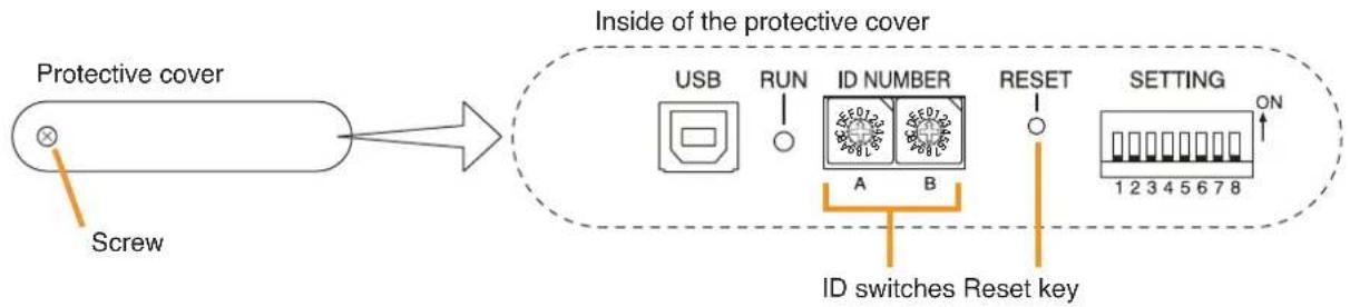
flowchart
graph LR
    A["Protective cover"] --> B["Screw"]
    B --> C["Inside of the protective cover"]
    C --> D["USB"]
    C --> E["RUN"]
    C --> F["ID NUMBER"]
    C --> G["RESET"]
    C --> H["SETTING"]
    D --> I["A"]
    E --> J["B"]
    F --> K["1 2 3 4 5 6 7 8"]
    G --> L["ON"]
    H --> M["ID switches Reset key"]
Step 2. Set the ID switches.
| ID switch Arrowhead | ID NUMBER | A | 0 | ||||||||
| B | 0 | 1 | 2 | 3 | 4 | 5 | 6 | 7 | |||
| Device number | 1 | 2 | 3 | 4 | 5 | 6 | 7 | 8 | |||
Note: The device number is set to No. 1 by default.
Step 3. Press the Reset key to reactivate the SX-2000AI or SX-2100AI.
Note
Reactivating the SX-2000AI or SX-2100AI stops broadcasts being made via that SX-2000AI or SX-2100AI unit.
Step 4. Replace the protective cover.
2.2.3. Changing the type of control outputs (SX-2100AI only)

WARNING
This change should only be performed by a qualified professional electrician. If users open the unit case or modify the unit, this may cause fire or electric shock.
All the contact outputs are of normally open type when shipped from the factory.
Each output can be converted into normally closed type by changing the jumper setting on the CIO circuit board.
Notes
- Turn off the power before starting this work.
- To avoid damage from static electricity, never touch the terminals themselves or any of the parts on the circuit board.
Step 1. Detach the SX-2100AI's top panel.
Note
Note the specific shapes of the different screws.
Top panel: M3 x 6 flat head machine screw (2 pieces)
Side panel: M3 x 6 binding head machine screw (4 pieces)

text_image
Top panel SX-2100AI CIO circuit boardStep 2. Change the jumper settings on the CIO circuit board.
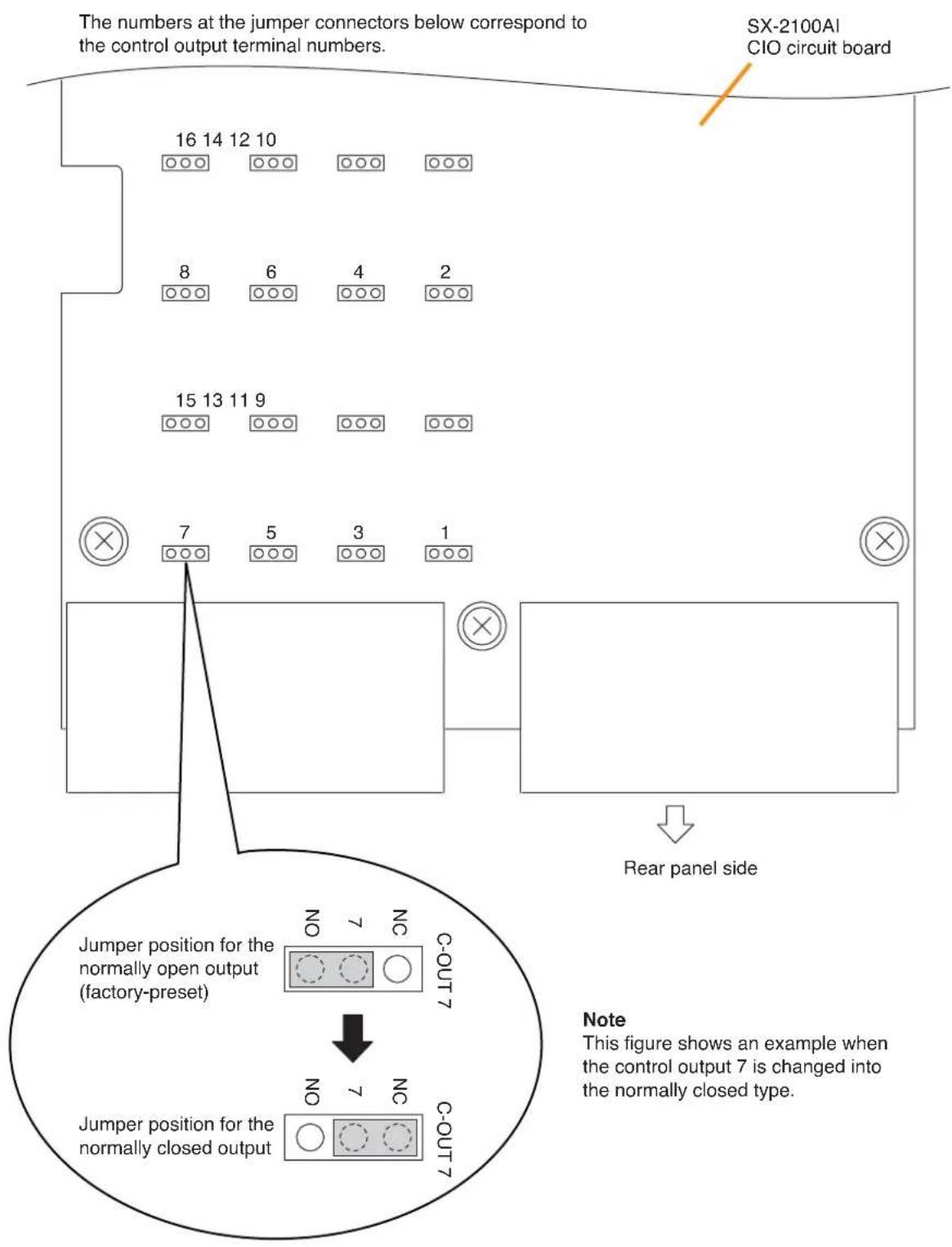
text_image
The numbers at the jumper connectors below correspond to the control output terminal numbers. SX-2100AI CIO circuit board 16 14 12 10 8 6 4 2 15 13 11 9 7 5 3 1 Rear panel side Jumper position for the normally open output (factory-preset) 7 NC COUT 7 NC Jumper position for the normally closed output 7 NC COUT Note This figure shows an example when the control output 7 is changed into the normally closed type.Step 3. Replace the top panel.
Note
In this event, note the specific shapes of the different screws. (See Step 1.)
2.3. SX-2000AO and SX-2100AO
2.3.1. Setting the device number
Notes
- When setting the device number for multiple SX-2000AO and SX-2100AO units, assign different numbers to each unit. The device number that can be used must not exceed the actual number of SX-2000AO and SX-2100AO units set using the SX-2000 Setting Software.
- If a device number is duplicated, then the SX-2000AO and SX-2100AO units assigned that number cannot be controlled by the SX-2000 system.
Step 1. Remove the protective cover on the SX-2000AO's or SX-2100AO's front panel by unscrewing it with a Phillips screwdriver.
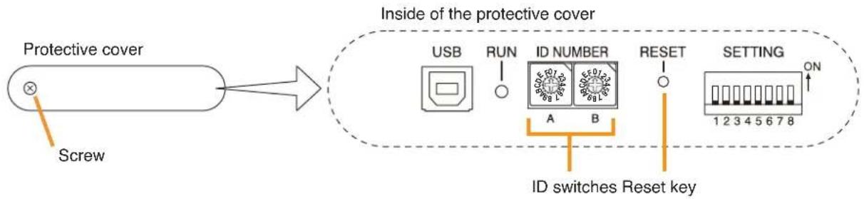
flowchart
graph LR
    A["Protective cover"] --> B["Screw"]
    B --> C["Inside of the protective cover"]
    C --> D["USB"]
    C --> E["RUN"]
    C --> F["ID NUMBER"]
    C --> G["RESET"]
    C --> H["SETTING"]
    H --> I["ON"]
    C --> J["ID switches Reset key"]
Step 2. Set the ID switches.
| ID switch Arrowhead | ID NUMBER | A | 0 | |||||||||||||||||
| B | 0 | 1 | 2 | 3 | 4 | 5 | 6 | 7 | 8 | 9 | A | B | C | D | E | F | ||||
| Device number | 1 | 2 | 3 | 4 | 5 | 6 | 7 | 8 | 9 | 1 | 0 | 1 | 1 | 2 | 1 | 3 | ||||
| ID switch Arrowhead | ID NUMBER | A | 1 | |||||||||||||||||||
| B | 0 | 1 | 2 | 3 | 4 | 5 | 6 | 7 | 8 | 9 | A | B | C | D | E | F | ||||||
| Device number | 17 | 18 | 19 | 20 | 21 | 22 | 23 | 24 | 25 | 26 | 27 | 28 | 29 | 30 | 31 | 32 | ||||||
Note: The device number is set to No. 1 by default.
Step 3. Press the Reset key to reactivate the SX-2000AO or SX-2100AO.
Note
Reactivating the SX-2000AO or SX-2100AO stops broadcasts being made via that SX-2000AO or SX-2100AO unit.
Step 4. Replace the protective cover.
2.3.2. 24 V Emergency cutoff input settings (DIP switch 8 operation) (SX-2000AO only)
The 24 V Emergency cutoff input can be set to be enabled or disabled.
Once enabled when the SX-2000 system is combined with an emergency broadcast system, a 24 V DC is normally kept being supplied to this 24 V emergency cutoff input terminal and is cut off (24 V emergency cutoff function) in emergency situations. This interrupts the general-purpose broadcast from the SX-2000, allowing the emergency broadcast to override it. At the same time, the EMERGENCY indicators flash, one on the SX-2000SM's front panel and others in the fluorescent displays on the front panels of SX-2000AOs in 24 V emergency cutoff state.
Note
When using this input terminal in combination with an emergency broadcast system, set DIP switch 8 to ON.
Step 1. Remove the protective cover on the SX-2000AO's front panel by unscrewing it with a Phillips screwdriver.

flowchart
graph LR
    A["Protective cover"] --> B["Screw"]
    B --> C["Inside of the protective cover"]
    C --> D["USB"]
    C --> E["RUN"]
    C --> F["ID NUMBER"]
    C --> G["RESET"]
    C --> H["SETTING"]
    H --> I["1 2 3 4 5 6 7 8"]
    H --> J["ON"]
    K["Reset key"] --> L["DIP switch"]
Note: Switch 8 is set to OFF by default.
Step 2. Set the DIP switch.
2-1. If using the 24 V emergency cutoff input, set DIP switch 8 to ON.

text_image
ON 1 2 3 4 5 6 7 82-2. If not using the 24 V emergency cutoff input, set DIP switch 8 to OFF.
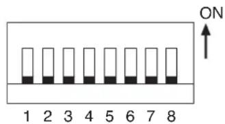
text_image
ON 1 2 3 4 5 6 7 8Step 3. Replace the protective cover.
2.3.3. Converting an output into a transformer-balanced output (SX-2000AO only)

WARNING
This conversion should only be performed by a qualified professional electrician. If users open the unit case or modify the unit, this may cause fire or electric shock.
The output can be changed from an electronically-balanced output to a transformer-balanced output with the additional use of an optional IT-450 transformer.
Notes
- Turn off the power before starting this work.
- To avoid damage from static electricity, never touch the terminals themselves or any of the parts on the circuit board.
Step 1. Detach the SX-2000AO's top panel.
Note
Note the specific shapes of the different screws.
Top panel: M3 x 6 flat head machine screw (2 pieces)
Side panel: M3 x 6 binding head machine screw (4 pieces)

text_image
Top panel SX-2000AO Link circuit boardStep 2. Remove the flat cable and connectors (10P and 11P) connected to the link circuit board.
- Detaching a flat cable
To remove the flat cable, first raise the lock lever on top of the connector.
Front panel side
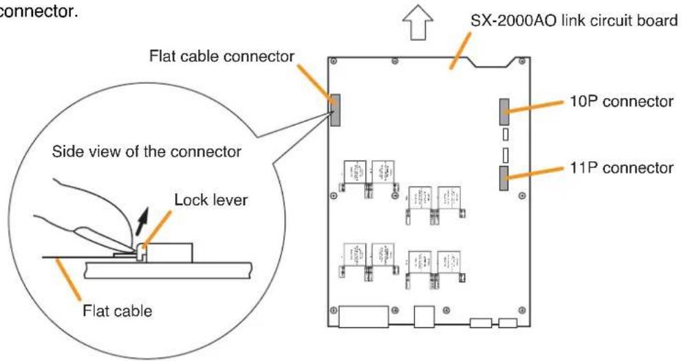
text_image
connector. SX-2000AO link circuit board Flat cable connector 10P connector 11P connector Side view of the connector Lock lever Flat cable- Inserting a flat cable

text_image
Lock lever Flat cable Conductor surfaceRaise the lock lever. Lower the lock lever. Insert the flat cable with its conductor surface facing downward.
Note
Pivot the lock lever on its fulcrum to open and close it.
Avoid gripping the lock lever with the fingers or twisting it.
Also, do not apply force in the horizontal direction.
Incorrect usage could damage the lock lever.
natural_image
Diagram showing a mechanical or electrical setup with intersecting lines and arrows, no text or symbols present.
natural_image
Illustration of a hand holding a pen with a cross mark above, no text or symbols presentStep 3. Remove the 10 circuit board mounting screws, then remove the link circuit board.
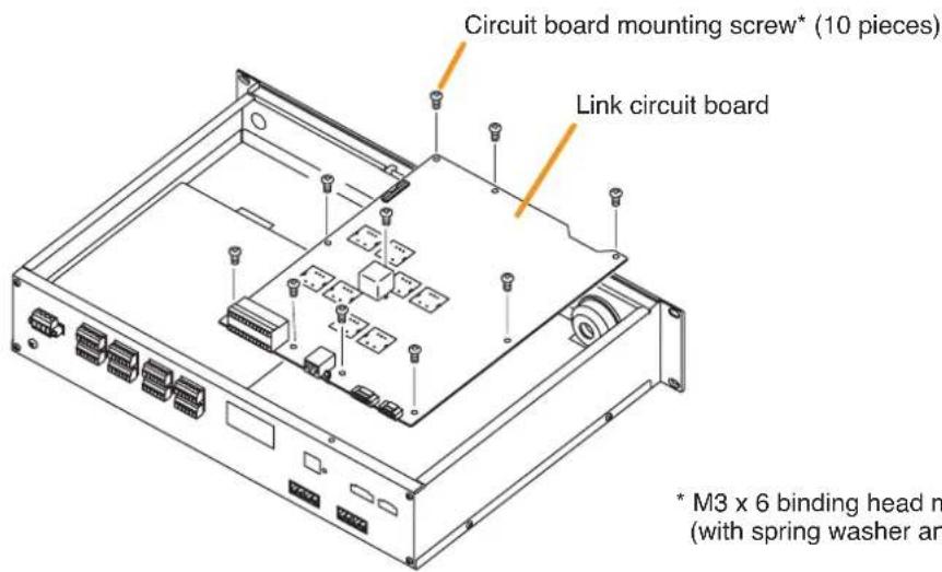
text_image
Circuit board mounting screw* (10 pieces) Link circuit board * M3 x 6 binding head m (with spring washer an* M3 x 6 binding head machine screw (with spring washer and plain washer)

flowchart
graph TD
    A["OUTPUT 8"] --> B["IT-450 mounting position"]
    C["UT 6"] --> D["IT-450 mounting position"]
    E["OUTPUT 2"] --> F["IT-450 mounting position"]
    G["UT 7"] --> H["IT-450 mounting position"]
    I["OUTPUT 4"] --> J["IT-450 mounting position"]
    K["UT 5"] --> L["IT-450 mounting position"]
    M["OUTPUT 1"] --> N["IT-450 mounting position"]
    O["UT 3"] --> P["IT-450 mounting position"]
    Q["Example of how to cut jumpers when a transformer is installed in the place of Output 1 (T101)."]
    style A fill:#f9f,stroke:#333
    style C fill:#f9f,stroke:#333
    style E fill:#f9f,stroke:#333
    style G fill:#f9f,stroke:#333
    style I fill:#f9f,stroke:#333
    style M fill:#f9f,stroke:#333
    style Q fill:#ccf,stroke:#333
    style Q fill:#ccf,stroke:#333
    style Q fill:#ccf,stroke:#333
    style Q fill:#ccf,stroke:#333
    style Q fill:#ccf,stroke:#333
Step 4. Install the IT-450 transformer in the designated transformer installation place for outputs 1 – 8, then solder it in place.
Output 1: T101; output 2: T102; output 3: T103; output 4: T104; output 5: T105; output 6: T106; output 7: T107; output 8: T108
Step 5. Cut the jumper wires on both sides of the installed transformer.
Note
Take care to ensure that no fragments of the cut jumpers contact the transformer case.
Step 6. Replace the link circuit board and top panel.
Notes
- Note the specific shapes of the different screws when replacing the link circuit board and top panel. (See Steps 1 and 3.)
- When connecting the flat cable to the link circuit board, handle the connector with care. (See Step 2.)
2.3.4. Changing the method of power supply for the control input signal applied to the Local Audio Control Input Terminal (SX-2100AO only)

WARNING
This conversion should only be performed by a qualified professional electrician. If users open the unit case or modify the unit, this may cause fire or electric shock.
This power is factory-preset to be supplied from the inside of the SX-2100AO. By changing the jumper setting on the Link circuit board inside the SX-2100AO, the power can be cut off from the SX-2100AO, allowing to be supplied from an external power source.
Notes
- Turn off the power before starting this work.
- To avoid damage from static electricity, never touch the terminals themselves or any of the parts on the circuit board.
Step 1. Detach the SX-2100AO's top panel.
Note
Note the specific shapes of the different screws.
Top panel: M3 x 6 flat head machine screw (2 pieces)
Side panel: M3 x 6 binding head machine screw (4 pieces)

text_image
Top panel SX-2100AO Link circuit boardStep 2. Change the jumper settings on the link circuit board.
Note that the SJP901 is for the Local Input 1, and the SJP-902 for the Local Input 2.

text_image
Front panel side SX-2100AO link circuit board Local input 1 Local input 2 SJP901 SJP902 Using the internal power supply (Factory-preset) Using an external power supply SJP902 SJP902 InterEXT InterEXT NoteThe figure shows an example for supplying the power from an external device to Local Input 2.
Step 3. Replace the top panel.
Note
Note the specific shapes of the different screws when replacing the top panel. (See Step 1.)
Step 4. Apply 12 - 40 V DC to Pin 6 of the Local Audio Control Input Terminal (RJ45).
A built-in current limiting resistor of 4.4 kΩ limits the current to 10 mA or less.
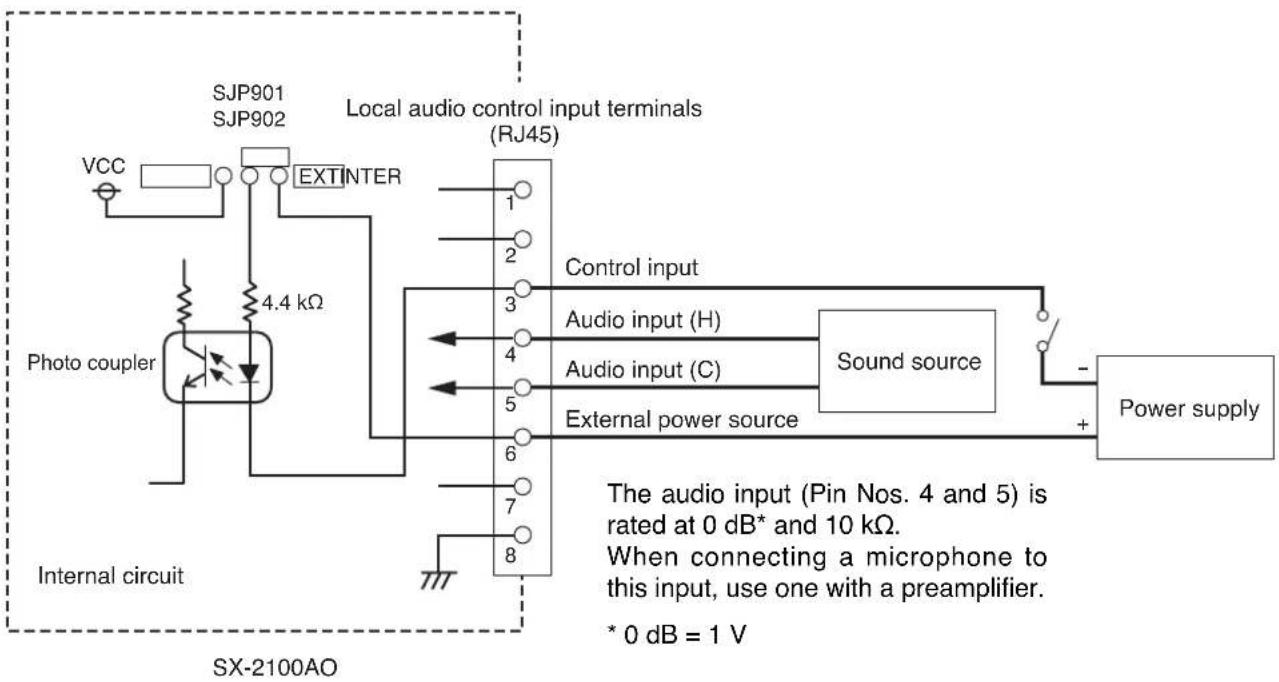
flowchart
graph TD
    A["Photo coupler"] -->|4.4 kΩ| B["SJP901"]
    B --> C["VCC"]
    C --> D["SJP902"]
    D --> E["EXTINTER"]
    E --> F["Local audio control input terminals (RJ45)"]
    F --> G["Control input"]
    G --> H["Audio input (H)"]
    G --> I["Audio input (C)"]
    G --> J["External power source"]
    H --> K["Sound source"]
    I --> K
    J --> K
    K --> L["Power supply"]
    style A fill:#f9f,stroke:#333
    style L fill:#ccf,stroke:#333
Note
The factory-preset wiring differs from the figure above. For details, refer to p. 97.
2.4. SX-2000CO
[Method to turn the control outputs on when the general urgency all-call is made]

WARNING
This change should only be performed by a qualified professional electrician. If users open the unit case or modify the unit, this may cause fire or electric shock.
The SX-2000CO's control outputs are factory-preset to turn off when the general urgency all-call is made. By changing the internal DIP switch settings for the desired control outputs, the corresponding outputs can be turned on when the general urgency all-call is made.
Notes
• Turn off the power before starting this work.
- To avoid damage from static electricity, never touch the terminals themselves or any of the parts on the circuit board.
Step 1. Detach the SX-2000CO's top panel.
Note
Note the specific shapes of the different screws.
Top panel: M3 x 6 flat head machine screw (2 pieces)
Side panel: M3 x 6 binding head machine screw (4 pieces)

text_image
Top panel SX-2000COCO circuit board
Step 2. Perform DIP switch settings on the CO circuit board.
The control output channels correspond to the DIP switches on the CO circuit board as follows.
Control output channels 1 - 8: SW301
Control output channels 9 - 16: SW302
Control output channels 17-24: SW303
Control output channels 25-32: SW304
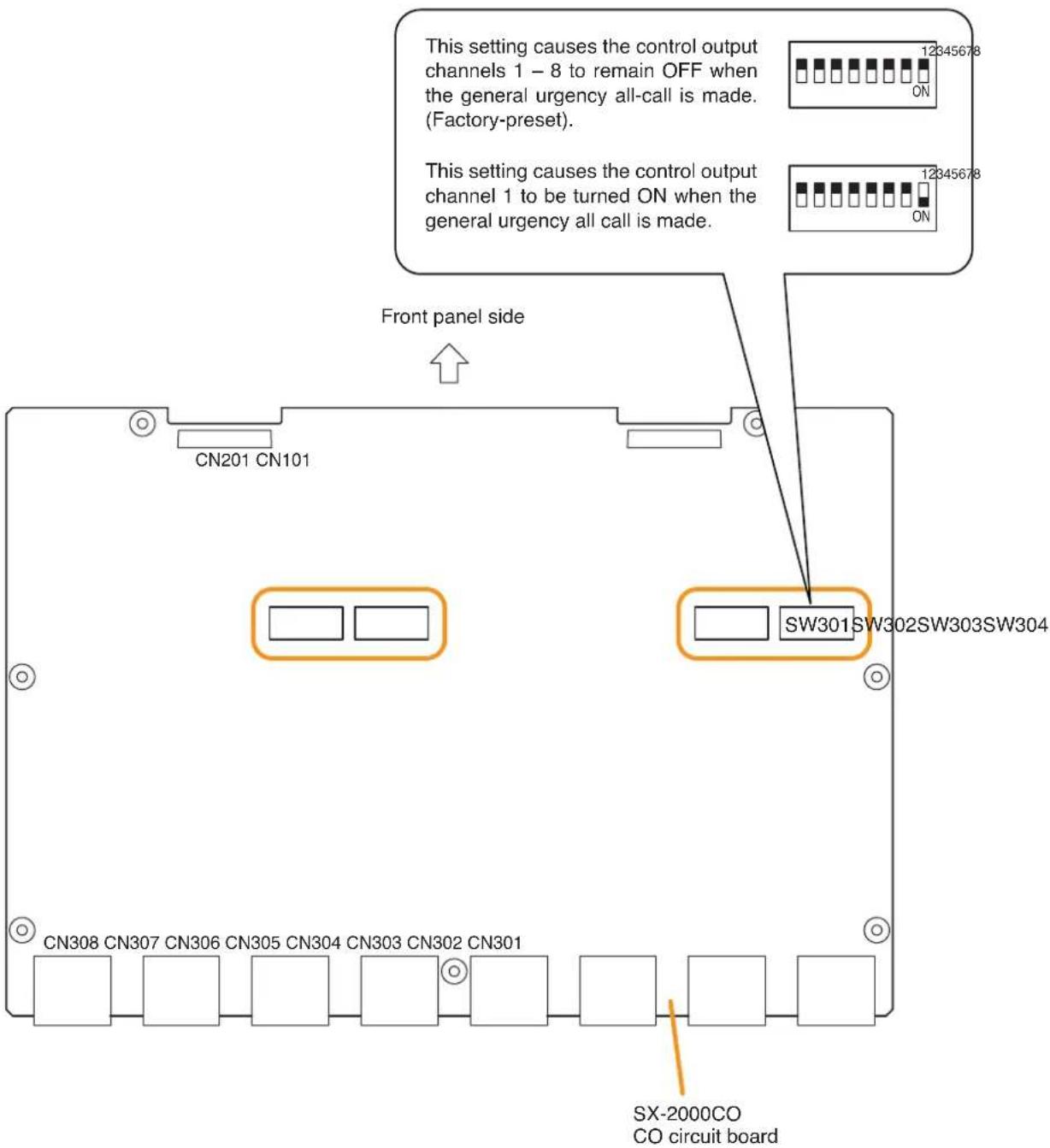
text_image
This setting causes the control output channels 1 – 8 to remain OFF when the general urgency all-call is made. (Factory-preset). This setting causes the control output channel 1 to be turned ON when the general urgency all call is made. Front panel side CN201 CN101 SW301SW302SW303SW304 CN308 CN307 CN306 CN305 CN304 CN303 CN302 CN301 SX-2000CO CO circuit boardStep 3. Replace the top panel.
Note
Note the specific shapes of the different screws when replacing the top panel. (See Step 1.)
2.5. RM-200SF, RM-200SA, and RM-210
2.5.1. RM-200SF and RM-200SA device number settings (DIP switches 1 - 3 operation)
Set device numbers (ID numbers) using DIP switches 1 – 3 located on the bottom panel of the RM-200SF and the side panel of the RM-200SA.
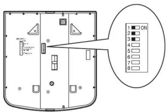
text_image
ON 1 2 3 4 5 6 7 8RM-200SF bottom RM-200SA side

text_image
123456 ONNote
Connect one RM-200SF or RM-200SA to each input of SX-200RM mounted in the SX-2000AI or SX-2100AI. The input channels to which the RM-200SF and RM-200SA can be connected must have been assigned using the SX-2000 Setting Software, and each connected RM-200SF's and RM-200SA's device number must match the input channel number of the SX-2000AI or SX-2100AI to which it is connected.
[Setting example]

flowchart
graph LR
    A["RM-200SF Device number 1"] --> B["CH 1 CH 2"]
    C["RM-200SA Device number 3"] --> D["CH 3 CH 4"]
    E["RM-200SA Device number 5"] --> F["CH 5 CH 6"]
    G["RM-200SA Device number 6"] --> H["CH 7 CH 8"]
    B --> I["SX-200RM"]
    D --> J["SX-200RM"]
    F --> K["SX-200RM"]
    H --> L["SX-200RM"]
| Device number DIP switch 3 DIP switch 2 DIP switch 1 RM-200SF RM-200SA | |||||
| 1 OFF OFF OFF | 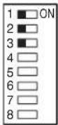 | 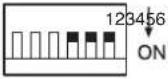 | |||
| 2 OFF OFF ON | 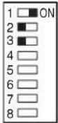 | 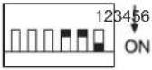 | |||
| 3 OFF ON OFF | 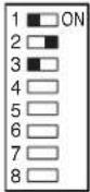 |  | |||
| 4 OFF ON ON | 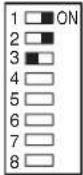 | 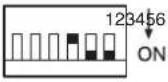 | |||
| 5 ON OFF OFF | 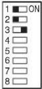 | 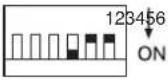 | |||
| 6 ON OFF ON |  | 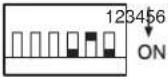 | |||
| 7 ON ON OFF |  | 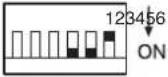 | |||
| 8 | O | N | O |  | 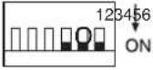 |
Note: Device number is set to "1" by default.
2.5.2. Adjusting microphone sensitivity
(RM-200SF: DIP switch 5 operation or RM-200SA: DIP switch 4 operation)
Since the DIP switch can be set to make the broadcast status indicator show output signal level, ^* adjust the microphone sensitivity using the following procedure:
* When the microphone is in use, the indicator shows the output signal level. When the microphone is not in use, it shows the broadcast status.
Step 1. Set DIP switch 5 on the bottom surface of the RM-200SF to ON or DIP switch 4 on the side of the RM-200SA to ON.
The broadcast status indicator on top panel of the RM-200SF or RM-200SA switches to show the output signal level.
Note
Both DIP switches are set to OFF by default.

text_image
Technical diagram showing internal components and a device with labeled indicators and a magnified inset highlighting a specific component.RM-200SF bottom RM-200SA side
Step 2. Speak into the microphone.
The broadcast status indicator shows the microphone's output signal level.
The following table shows how the output level is shown.
| Indicator Color | Output Signal Level |
| Lights red | Over 0 dB |
| Lights green | -20 dB to 0 dB Appropriate level |
| Off | Under -20 dB |

text_image
TOA HM-200SF KIC SP CPU 0 0 0 0 0 0 0 0 0 0 0 0 0 0 0 0 0 0 0 0 0 0 0 0 0 0 0 0 0 0 0 0 0 0 0 0 0 0 0 0 0 0 0 0 0 0 0 0 0 0 0RM-200SA topRM-200SF top

text_image
TOA BM-200SABroadcast status indicator
Broadcast status indicator
Step 3. Using the microphone volume control, adjust the microphone input sensitivity to an appropriate level (until the broadcast status indicator lights green).
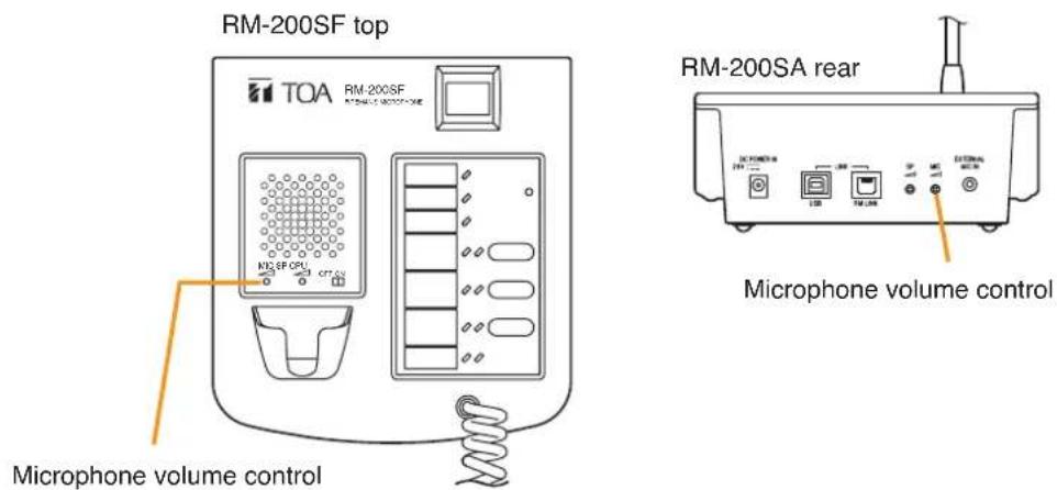
text_image
RM-200SF top TOA RM-200SF RM-200SF top MICR SF CPU CTT AU Microphone volume control RM-200SA rear MICR SF CPU CTT AU Microphone volume control 1.5V 1.5V 1.5V 1.5V 1.5V 1.5V 1.5VStep 4. Set DIP switch 5 of the RM-200SF to OFF or DIP switch 4 of the RM-200SA to OFF.
Note
Be sure to set both DIP switches to OFF after adjusting the microphone input sensitivity.
2.5.3. CPU OFF function (general urgency all-call) settings
(RM-200SF: DIP switch 6 operation or RM-200SA: DIP switch 5 operation)
The CPU OFF function permits the all-zone calls to be made from the RM-200SF or RM-200SA by bypassing the CPU*1 normally used by the SX-2000 system and using an analog link instead. This function is usually used if a system failure is preventing normal broadcasts from being made. Announcement from the RM-200SF can be made to all zones within the system only while the Talk Switch is being pressed with the CPU switch on its top panel set to OFF, or announcement from the RM-200SA can be made to the said zones while its General Urgency All-Call key is being held down for 4 seconds or more. Whether or not this function is available can be set using DIP switch 6 on the bottom panel of the RM-200SF or DIP switch 5 on the side panel of the RM-200SA. (Regarding how to make such broadcasts, see the separate Operating Instructions, "Operation.")
If the SX-2000 system receives a 24 V emergency cutoff signal ^*2 , the general urgency all-call using the CPU OFF function is disabled because the emergency system other than the SX-2000 system takes precedence over the SX-2000 system.
*1 CPU is a central processing unit, which is built in the SX-2000SM, SX-2000AI, SX-2100AI, SX-2000AO, and SX-2100AO.
*2 In the SX-2000 system, a 24 V emergency cutoff input terminal that allows control of an emergency audio input is provided on the SX-2000AO's rear panel. When the SX-2000 system is combined with another emergency system, a 24 V DC is normally kept being supplied to this 24 V emergency cutoff input terminal and is cut off in emergency situations. This interrupts the general-purpose broadcast from the SX-2000, allowing the emergency system other than the SX-2000 system to override it.

text_image
ON 123456 ONRM-200SF bottom RM-200SA side
Note
Set the CPU OFF function to "Disabled" as in the table below for systems that do not use the analog link.
| CPU OFF Function(General urgencyall-call) | DIP Switch | RM-200SARM-200SF | |
| Enabled | ON(Default position) |  |  |
| Disabled | OFF | 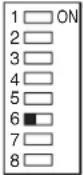 |  |
2.5.4. RM Communication function setting
(RM-200SF: DIP switch 4 operation or RM-200SA: DIP switch 6 operation)
Set the RM communication function to the Automatic Setting (OFF) or 9600 bps Fixed (ON). Normally set to the Automatic Setting (OFF). Communication may become unstable depending on conditions when cable length between the unit and remote microphone is great. In such cases, set the switch to 9600 bps Fixed (ON). Be sure to set the DIP switches of all remote microphones in the system to the same position.
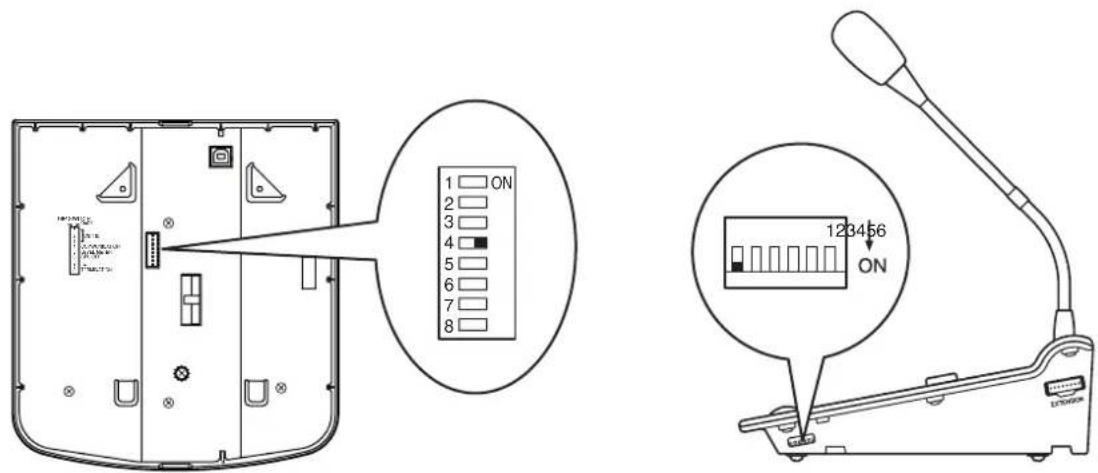
text_image
1 ON 2 3 4 5 6 7 8 123456 ONRM-200SF bottom RM-200SA side
| DIP SwitchRM | Communication function | RM-200SARM-200SF | |
| Automatic Setting | OFF(Default position) |  |  |
| 9600 bps Fixed | ON | 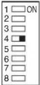 | 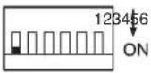 |
2.5.5. Using an external microphone (RM-200SA only)

WARNING
This work should only be performed by a qualified professional electrician. If users open the unit case or modify the unit, this may cause fire or electric shock.
Changing the jumper settings on the RM-200SA's circuit board causes an external microphone to be used.
Notes
- Turn off the power before starting this work.
• To avoid damage from static electricity, never touch the parts on the circuit board.
Step 1. Unscrew 8 screws indicated by arrows in the figure at right, then detach the RM-200SA's upper case.
Note
Note the types of screws.
A: 3 x 8 tapping screw (white silver) ...... 6 pieces
B: 3 x 10 tapping screw (black) ..... 2 pieces
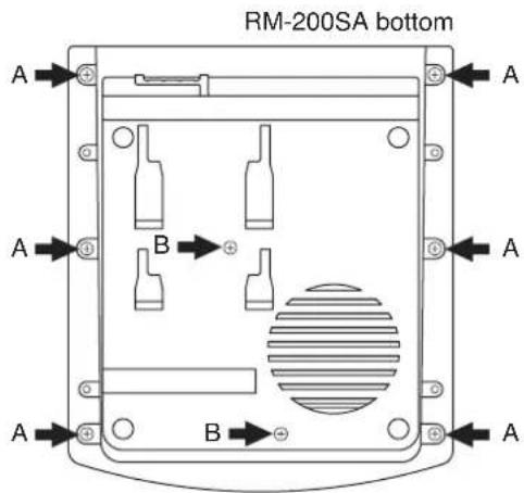
text_image
RM-200SA bottom A B A B A AStep 2. Set the jumper's position (SW301) on the circuit board attached to the bottom plate as shown below.
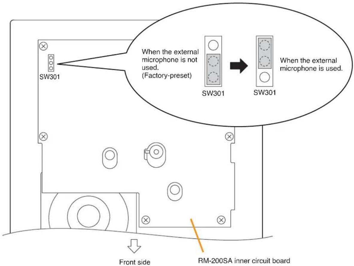
text_image
SW301 When the external microphone is not used. (Factory-preset) SW301 When the external microphone is used. SW301 When the external microphone is used. Front side RM-200SA inner circuit boardStep 3. Replace the RM-200SA's upper case.
Note
Note the types of screws when replacing the upper case (See Step 1.)
[Plug for connection to the RM-200SA's external input terminal]
Connect the microphone's signal line to the tip and its shield line to the sleeve of the stereo mini plug or monaural mini plug.
![TOA D-921F - [Plug for connection to the RM-200SA's external input terminal] - 1](/content/2026/06/1214100/images/2c608164f7077ba28a8d21a4f1c589622770636f9d4a6e887a2a59d54d505fc6.jpg)
text_image
[Stereo mini plug] Sleeve: Ground Tip: Signal lineRing [Monaural mini plug] Sleeve: Ground Tip: Signal lineTip: The WH-4000A, YP-M101, or YP-M301 can be used for the external microphone.
2.5.6. Compressor function setting

WARNING
This work should only be performed by a qualified professional electrician. If users open the unit case or modify the unit, this may cause fire or electric shock.
The compressor function enables even large signals to be broadcast without distortion. (This function is factory-preset to ON.)
Notes
- Turn off the power before starting this work.
• To avoid damage from static electricity, never touch the parts on the circuit board.
[RM-200SF]
Step 1. Unscrew 5 screws in the figure at right, then detach the RM-200SF's bottom plate.
Note
Note the specific shapes of the different screws.
Inch screw (combination drive) No.6-32 x 1/4 (1) Tooth lock washer (1)
![TOA D-921F - [RM-200SF] - 1](/content/2026/06/1214100/images/40b3a35cbaca57809e11a94dfb6c320f4ede30e052a54845cda044f1f71b0d62.jpg)
text_image
RM-200SF bottom Tapping screw (Phillips) 3 x 8 (4)Step 2. Set the jumper's position (JP301) on the circuit board attached to the upper case as shown below.
![TOA D-921F - [RM-200SF] - 2](/content/2026/06/1214100/images/bcc04f08d62f7948436151f2b44f18560e31e8d9c4beebc7f27680df45cff780.jpg)
text_image
to the upper case as shown below. RM-200SF inner circuit board JP301 When the compressor function is used. (Factory-preset) JP301 When the compressor function is not used. JP301Step 3. Replace the RM-200SF's bottom plate.
Note: Note the specific shapes of the different screws when replacing the bottom plate. (See Step 1.)
[RM-200SA]
Step 1. Unscrew 8 screws indicated by arrows in the figure at right, then detach the RM-200SA's upper case.
Note
Note the types of screws.
A: 3 x 8 tapping screw (white silver) ...... 6 pieces
B: 3 x 10 tapping screw (black) ..... 2 pieces

text_image
RM-200SA bottom A B A B A AStep 2. Set the jumper's position (SW304) on the circuit board attached to the bottom plate as shown below.

text_image
SW304 When the compressor function is used. (Factory-preset) SW304 When the compressor function is not used. SW304 When the compressor function is used. (Factory-preset) Front side RM-200SA inner circuit boardStep 3. Replace the RM-200SA's upper case.
Note: Note the types of screws when replacing the upper case (See Step 1.)
2.5.7. Microphone fault detection function setting (RM-200SA only)

WARNING
This work should only be performed by a qualified professional electrician. If users open the unit case or modify the unit, this may cause fire or electric shock.
The RM-200SA is equipped with the microphone fault detection function, which can be set to OFF. (Factory-preset to ON)
Notes
- Turn off the power before starting this work.
• To avoid damage from static electricity, never touch the parts on the circuit board.
Step 1. Unscrew 8 screws indicated by arrows in the figure at right, then detach the RM-200SA's upper case.
Note
Note the types of screws.
A: 3 x 8 tapping screw (white silver) ..... 6 pieces
B: 3 x 10 tapping screw (black) ..... 2 pieces
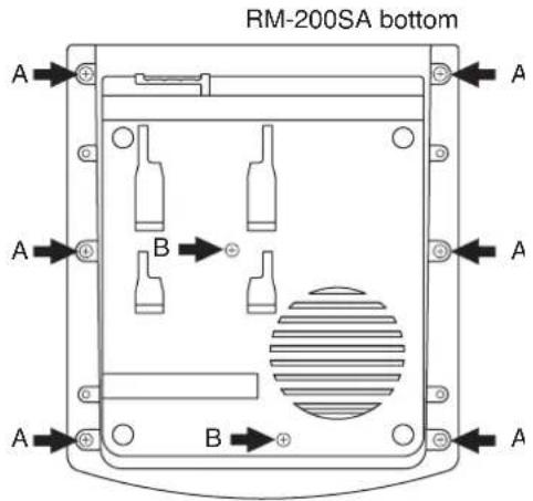
text_image
RM-200SA bottom A B A B AStep 2. Set the jumper's position (SW303) on the circuit board attached to the bottom plate as shown below.
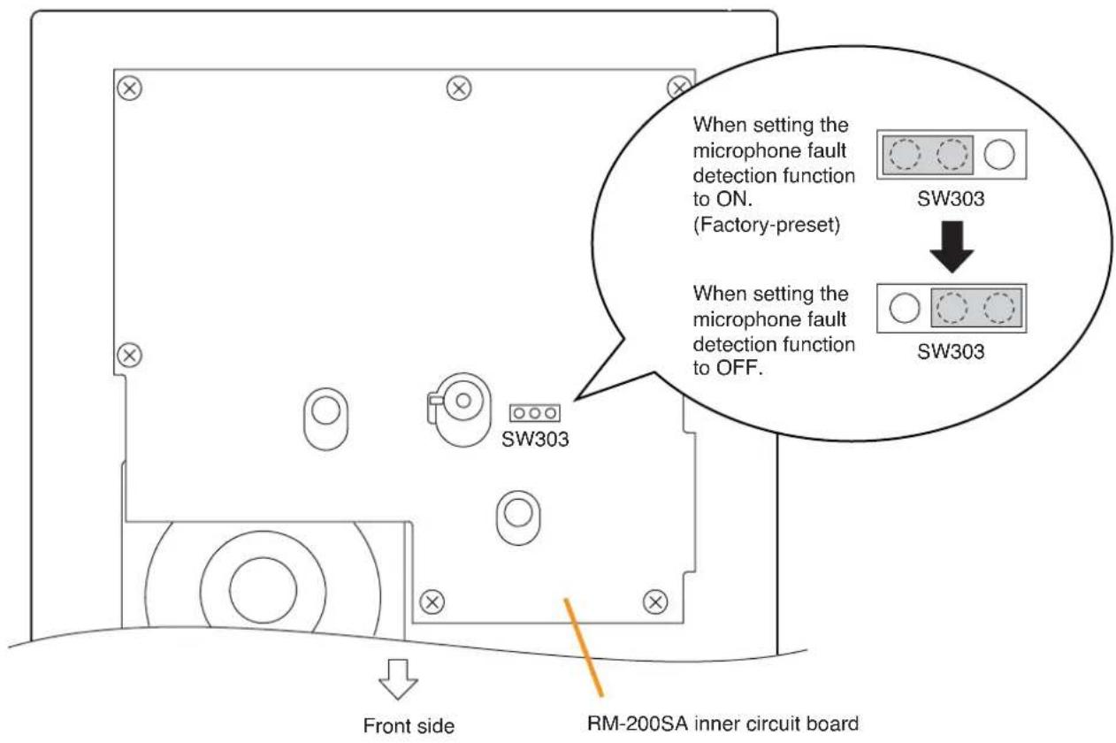
text_image
When setting the microphone fault detection function to ON. (Factory-preset) SW303 When setting the microphone fault detection function to OFF. SW303 SW303 Front side RM-200SA inner circuit boardStep 3. Replace the RM-200SA's upper case.
Note: Note the types of screws when replacing the upper case (See Step 1.)
2.5.8. Installing the RM-200SF on a wall
The RM-200SF is designed for on-wall installation.
[Mounting hardware]
To mount the RM-200SF on the wall, the following parts are required.
Wall mount bracket unit 1 (supplied with the RM-200SF)
Wall mounting screws
4 x 25 tapping screw for wooden wall .... 2 (supplied with the RM-200SF)
M3.5 x 20 screw for electrical box .... 2 (supplied with the RM-200SF)
[Ferrite cable clamp attachment]
The supplied ferrite clamp needs to be attached to the Link cable as illustrated below.
As its mounting timing differs depending on the installation way of the RM-200SF, mount the clamp in the appropriate installation step.
![TOA D-921F - [Ferrite cable clamp attachment] - 1](/content/2026/06/1214100/images/04c8c35710f58a57cfb99e4598ed38d6039b642707cc7ef53e438b703ad70eb7.jpg)
text_image
RM-200SF Link cable Loop the cable one turn. Ferrite clamp (Supplied with the RM-200SF)Mount the ferrite clamp (supplied with the RM-200SF) on the cable in a way that the cable is looped one turn as illustrated. (This countermeasure is for complying with the CE marking.)
[Installation]
Step 1. Install the wall mount bracket unit supplied with the RM-200SF on the wall.
1-1. Installing directly on the wall
Install the unit on the wall using 2 screws or more depending on the installation location.
The RM-200SF comes with 2 tapping screws 4 x 25 for direct wall mounting.
![TOA D-921F - [Installation] - 1](/content/2026/06/1214100/images/496a9b22a91bf99a0559b3f17cdc730f0f8cfb0f7020dabfa9f1c3431f97fa1f.jpg)
WARNING
• Install the unit only in a location that can structurally support the weight of the unit and the mounting bracket. Doing otherwise may result in the unit falling down and causing personal injury and/or property damage.
- Be sure to install the bracket on the wall using 2 or more screws.
Notes
- Six mounting holes indicated by arrows in the figure below can be used for securing.
- When securing the unit with 2 screws, be sure to use a pair of holes located in the middle of the Bracket A.

text_image
Technical diagram of an electrical component with labeled pins and internal wiring, showing connections and directional arrows.Wall mount bracket unit (supplied with the RM-200SF)
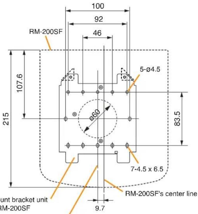
text_image
100 92 46 RM-200SF 107.6 215 5-Ø4.5 83.5 7-4.5 x 6.5 RM-200SF's center line 9.7 ount bracket unit RM-200SFWall mount bracket unit's center line
Unit: mm
1-2. Installing to a 1-gang electrical box
(1) Unscrew 3 screws (indicated by arrows in the figure at right) that fix the Bracket A to the Bracket B of the wall mount bracket unit.
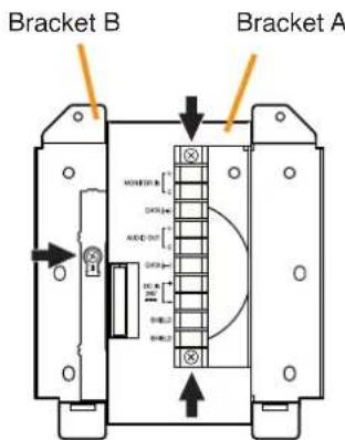
text_image
Bracket B Bracket A MOUNTED DOUT MOUNTED DOUT MOUNTED DOUT MOUNTED DOUT MOUNTED DOUT MOUNTED DOUT MOUNTED DOUT MOUNTED DOUT MOUNTED DOUT MOUNTED DOUT MOUNTED DOUT MOUNTED DOUT MOUNTED DOUT MOUNTED DOUT MOUNTED DOUT NUTTER NUTTER NUTTER NUTTER NUTTER NUTTER NUTTER NUTTER NUTTER NUTTER NUTTER NUTTER NUTTER NUTTER NUTTER NUTTER NUTTER NUTTER NUTTER NUTTER NUTTERWall mount bracket unit (supplied with the RM-200SF)
(2) Slide the Bracket A as show below to detach it from the Bracket B.

text_image
Bracket A Bracket B Slide the Bracket A upward, then pull it toward you.(3) Attach the Bracket B to the electrical box using 2 screws M3.5 x 20 supplied with the RM-200SF.

text_image
Screw holes for mounting to the electrical box (2 places) Bracket B Ø60 83.5 Unit: mmWARNING
• Install the unit only in a location that can structurally support the weight of the unit and the mounting bracket. Doing otherwise may result in the unit falling down and causing personal injury and/or property damage.
- Be sure to use 2 screws when mounting the bracket to the electrical box.
(4) Replace the Bracket A.
Reverse the procedures (1) and (2) above.
Note
Take care not to pinch the routed link cable between the Brackets A and B.
Step 2. Connect the link cable to the screw terminal block.

text_image
Bracket A Link cable Bracket BWall mount bracket unit (supplied with the RM-200SF)
Note
Put the link cable inside the Bracket A after connection completion.
Do not allow the link cable to protrude.
The cable may be damaged if it protrudes when the bracket unit is installed onto the wall.
Step 3. Plug the RM-200SF's extension connector into the connector port on the wall mount bracket unit.
Step 4. Attach the RM-200SF unit to the wall mount bracket unit.
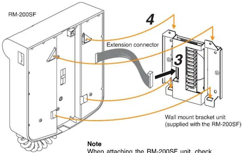
text_image
RM-200SF Extension connector 4 3 Wall mount bracket unit (supplied with the RM-200SF) Note When attaching the RM-200SF unit, checkWhen attaching the RM-200SF unit, check that the extension connector is not pinched.
[When the RM-200SF is installed in a wall box]
When the RM-200SF is installed in a wall box (prepare separately), the box should measure at least 300 mm wide x 315 mm high as illustrated below.
![TOA D-921F - [When the RM-200SF is installed in a wall box] - 1](/content/2026/06/1214100/images/d8d46fb131f4f0064618e01c872c3653a22f090ba8f5359c9325a168b00d7723.jpg)
text_image
300 min. 50 min. 50 min. 315 min. 50 min. 50 min. Effective depth: 100 min. Mounting base surface Rear surface of the front door Inside dimension of the boxUnit: mm
2.5.9. RM-200SA expansion with the addition of the RM-210 (Installed on a flat surface)
When adding an RM-210 Remote Microphone Extension to expand the RM-200SA, use the RM-210's Extension cable and included Linkage Bracket to link the 2 microphones. After DIP switch setting completion, follow the procedures below.
[Mounting hardware (supplied with the RM-210)]
Linkage Bracket A 2
Linkage Bracket B 1
Screw 12
Step 1. Turn over both the RM-200SA and the RM-210, and keep them in close contact with each other.
Step 2. Connect between both units using the extension cable supplied with the RM-210.
Step 3. Using 4 supplied screws indicated by arrows and Linkage Bracket B, link both units together.
Step 4. Using 8 supplied screws indicated by arrows and 2 pieces of Linkage Bracket A, fix both units securely.
Note: To add another RM-210 to the installed RM-210, use the similar procedures as in this section.
![TOA D-921F - [Mounting hardware (supplied with the RM-210)] - 1](/content/2026/06/1214100/images/d34f4855d9767e19a52232f00a3ed690bb74a9f3f82dab410d10e2a4070702c1.jpg)
text_image
2 Extension cable (Supplied with RM-210) RM-210 3 Linkage Bracket B RM-200SA [Bottom side]![TOA D-921F - [Mounting hardware (supplied with the RM-210)] - 2](/content/2026/06/1214100/images/4938c58483d49456fa94969d7aa966014dd10776f35c6e328926d61cac1dc49d.jpg)
text_image
4 Linkage Bracket A RM-210 RM-200SA [Bottom side]Notes
- Because the Linkage Bracket A is provided with 2 spare screw holes, use them to link the 2 units if the designated screw threaded holes are damaged.
- If incorrect or loose connection is found between both units, loosen all the bracket fixing screws to disassemble the units and then link them again with the screws.
2.5.10. Installing the RM-200SA on a wall
[Mounting hardware]
To mount the RM-200SA on the wall, the following parts are required.
Wall mounting bracket for the RM-210 (model WB-RM200) ..... 1 (optional)
M3.5 x 20 screw for electrical box .... 2 (supplied with the WB-RM200)
4 x 25 tapping screw for wooden wall .... 2 (supplied with the WB-RM200)
Step 1. Attach the WB-RM200 Wall-Mounting Bracket on the wall.
In this case, leave the LINK cable out of the notch in the bracket.
Note
Since there are 2 types of mounting screws for an electrical box and for wall. Select ones according to the mounting method.

WARNING
• Install the unit only in a location that can structurally support the weight of the unit and the mounting bracket. Doing otherwise may result in the unit falling down and causing personal injury and/or property damage.
- Be sure to use 2 screws when mounting the bracket to the wall.
[WB-RM200 mounting dimensions]
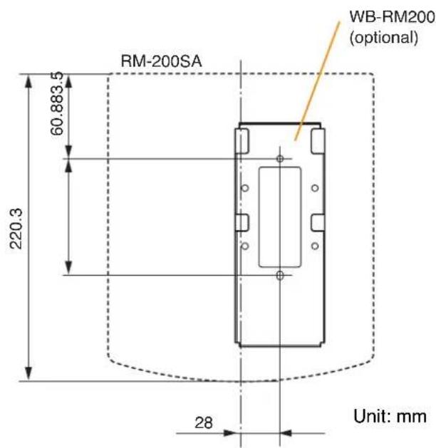
text_image
RM-200SA 60.883.5 220.3 28 Unit: mm WB-RM200 (optional)Step 2. Hook the bottom surface of the RM-200SA onto the WB-RM200.
Step 3. Plug the LINK cable into the RM-200SA's LINK terminal (RM LINK).
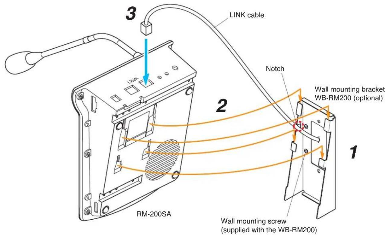
text_image
LINK cable 3 2 Notch Wall mounting bracket WB-RM200 (optional) 1 RM-200SA Wall mounting screw (supplied with the WB-RM200)2.5.11. Installing the RM-210 on a wall
[Mounting hardware]
To mount the RM-210 on the wall, the following parts are required.
Wall mounting bracket for the RM-210 (model WB-RM200) ..... 1 (optional)
M3.5 x 20 screw for electrical box .... 2 (supplied with the WB-RM200)
4 x 25 tapping screw for wooden wall .... 2 (supplied with the WB-RM200)
Step 1. Mount the RM-200SF or RM-200SA on the wall. (See p. 75 and p. 79.)
Step 2. Attach the WB-RM200 Wall-Mounting Bracket for mounting the RM-210 on the wall.
[WB-RM200 mounting dimensions]
![TOA D-921F - [Mounting hardware] - 1](/content/2026/06/1214100/images/7444185328a594b57edf82ea519004c1f67f4777568d400f7d05662dea40ce2e.jpg)
text_image
100 92 46 50 30 WB-RM200 (Optional) WB-RM200 (Necessary if one more RM-210 is added.) RM-200SF 5-Ø4.5 RM-210 107.6 83.5 71.5 102.8 220.3 215 Ø60 7-4.5 x 6.5 Wall mount bracket unit for the RM-200SF Wall mount bracket unit's center line 164.7 111 9.7 RM-200SF's center line![TOA D-921F - [Mounting hardware] - 2](/content/2026/06/1214100/images/da6bf1d5af3b8ee06154c5fe3d83ecba9407ae78e7196a4e84d48d600a78c548.jpg)
text_image
WB-RM200 (optional) WB-RM200 (optional) WB-RM200 (When adding another RM-210) RM-200SA RM-210 RM-210 60.883.5 220.3 71.5 6 30 28 123 111 Unit: mmStep 3. Using the extension cable supplied with the RM-210, connect the RM-200SF's or RM-200SA's side EXTENSION connector to the RM-210's side EXTENSION connector.
Step 4. Hook the bottom surface of the RM-210 onto the WB-RM200.
![TOA D-921F - [Mounting hardware] - 3](/content/2026/06/1214100/images/7d5576b15b890fc29f91b133af8b7a1274184761c82f2ce30bd5752aa05a3816.jpg)
text_image
RM-210 Extension cable (supplied with the RM-210) 3 1 RM-200SF 2 4 Wall mounting bracket WB-RM200 (optional)![TOA D-921F - [Mounting hardware] - 4](/content/2026/06/1214100/images/c43764f9868f711ce981a642f38b7cd85e30b2f7412d735c80b941a2cf95015d.jpg)
text_image
RM-210 Extension cable (supplied with the RM-210) 1 RM-200SA 2 Wall mounting bracket WB-RM200 (optional) 3 42.5.12. Creating remote microphone name labels
Using the SX-2000 Setting Software function, assigned names of preset RM-200SF, RM-200SA, and RM-210 Function keys can be printed out. Once printed, cut out the printed names with scissors to use them as corresponding name labels. The paper used for the name label must be under 0.2 mm in thickness.
Note
For creating and printing name labels using the SX-2000 Setting Software, see the separate Setting Software Instructions, "Labels for Remote Microphones."
[Inserting the name label]
- Fully insert the name label cut to the instructed size into the label entry slit.
• To remove the label, pull it out of the slit using the tip of knife blade.
![TOA D-921F - [Inserting the name label] - 1](/content/2026/06/1214100/images/29498e6186fbeab63c84c5aec0c32a61806d87572854bc94240f56d8be60e7f7.jpg)
text_image
Name label B (Created and printed using the SX-2000 Setting Software) Name label entry slit Name label entry slit Name label A (Created and printed using the SX-2000 Setting Software) RM-200SA TOA RM-210 Power Fault CPU OFF Emergency Reset Execution RV All Zones Talk Name label C (Created and printed using the SX-2000 Setting Software) RM-200SF TOA FM-200S FNDAR 216X Name label entry slit[If the name label is not printed correctly]
The name label created using the SX-2000 Setting Software may not be printed in correct size depending on the configuration environment of your PC. In such cases, try one of the methods described below.
(1) Preparation by hand
Copy the "Pattern paper for hand writing" on the next page. After writing a name, cut out the pattern paper aligning it with the cutting guidelines.
(2) Preparation by using a PC or word processor
Prepare and print according to the instructions given in the "Dimensional diagram for printing devices." Then cut out to the instructed size.
[Dimensional diagram for printing devices]
![TOA D-921F - [Dimensional diagram for printing devices] - 1](/content/2026/06/1214100/images/31568401a422d4c8d9665e67bfe2ec2805464e274bcd609aa3c92d59edef4040.jpg)
text_image
Name label A Cutting size: 30 x 110 mm 30 131313 39 110 13.5 13.5 13 x 9 (=117) 136 13 13.5 13 30 13 30 118 13 1321 21 21 13 13 Name label B Cutting size: 30 x 136 mm Name label C Cutting size: 29.6 x 118 mm[Pattern paper for hand writing]
Name label A Name label B
![TOA D-921F - [Pattern paper for hand writing] - 1](/content/2026/06/1214100/images/b208873961ffcc5a880feb48a3ade36ee421027777f98376f4339b562cf14ed6.jpg)
text_image
Cutting guideline![TOA D-921F - [Pattern paper for hand writing] - 2](/content/2026/06/1214100/images/3c2abb7fb7b6caa281449797dc4ea149c0c9b638f2d834a6a72e5569529c0c87.jpg)
natural_image
Pure geometric diagram with dashed lines and vertical borders, no text or symbols presentName label C
![TOA D-921F - [Pattern paper for hand writing] - 3](/content/2026/06/1214100/images/f7b5ac319dae0ff463fa945136c411383a818804611c6176d39e076de9036324.jpg)
natural_image
Pure geometric diagram with dashed lines and vertical lines, no text or symbols present2.6. VP-2064, VP-2122, VP-2241 and VP-2421 Power Amplifiers
2.6.1. Removing the VP Power Amplifier's top panel

natural_image
Isometric technical diagram of a server rack with mounting brackets and internal components (no text or labels)2.6.2. Changing the speaker line voltage
The speaker line voltage of the VP-2064, VP-2122, VP-2241 and VP-2421 is factory-preset to 100 V, however this can be changed to 50 V or 70 V following the procedures below.
Note
The speaker line failure detection functions are designed to perform on a 100-volt line of speaker. For the methods using a 70- or 50-volt line, please consult your TOA dealer.
Step 1. Remove the top panel referring to the above figure.
Step 2. Remove the connectors.
[VP-2064 Connector position]

text_image
CH1CH2CH3CH4 CN402 CN202CN3002 Rear panel[VP-2122 Connector position]
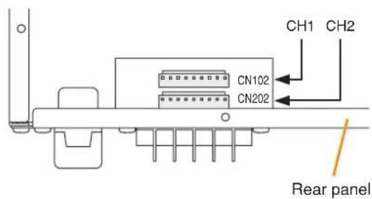
text_image
CH1 CH2 CN102 CN202 Rear panel[VP-2241 Connector position] [VP-2421 Connector position]

text_image
CN102 Rear panel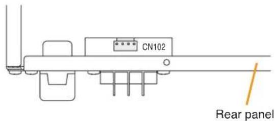
text_image
CN102 Rear panel[Channel-to-connector relationship]
| Model No. | VP-2064 VP-21 | 122 VP-2241 | VP-2421 | |
| Channel 1 | CN102 CN102 | CN102 CN102 | ||
| Channel 2 | CN202 CN202 | — | — | |
| Channel 3 | CN302 | — | — | — |
| Channel 4 | CN402 | — | — | — |
Step 3. Change wiring.
Disconnect a line and change it with the corresponding line. Refer to the figure below when removing.
To change to 50 V, change the Pin No. 1 line (white) with the Pin No. 3 line (blue).
To change to 70 V, change the Pin No. 1 line (white) with the Pin No. 2 line (purple).
[VP-2064/VP-2421 Connector Pin Assignment]
| Speaker line voltage | Pin No. | |||
| 1 | 2 | 3 | 4 | |
| 100 V (factory-preset voltage) White Purple | Blue Black | |||
| 70 V Purple White Blue Black | ||||
| 50 V Blue Purple White Black | ||||
[VP-2122/VP-2241 Connector Pin Assignment]
| Speaker line voltage | Pin No. | ||||||||
| 1 | 2 | 3 | 4 | 5 | 6 | 7 | 8 | 9 | |
| 100 V (factory-preset voltage) | White | Purple | Blue | Green | Yellow | Orange | Red | Brown | Black |
| 70 V | Purple | White | Blue | Green | Yellow | Orange | Red | Brown | Black |
| 50 V | Blue | Purple | White | Green | Yellow | Orange | Red | Brown | Black |
[Speaker line voltage/impedance]
| Speaker line voltage | VP-2064 | VP-2122 | VP-2241 | VP-2421 |
| 100 V | 167 Ω | 83 Ω | 41 Ω | 24 Ω |
| 70 V | 83 Ω | 41 Ω | 21 Ω | 12 Ω |
| 50 V | 41 Ω | 21 Ω | 10 Ω | 6 Ω |
[How to remove cables from connector]
Pull out the cable pressing the lock spring with a pointed object like tweezers as shown below.
![TOA D-921F - [How to remove cables from connector] - 1](/content/2026/06/1214100/images/71f9596d9917620e76c3a5214f4cc10f62fe7eb79205f299ea49f2e3711bda25.jpg)
text_image
Pull out the cable. Press the lock spring. 1 9Step 4. Insert the connectors back into their original positions on the circuit board.
Step 5. Replace the top panel.
2.6.3. Installing the VP-200VX Power Amplifier Input Module in the VP Power Amplifiers
Step 1. Remove the top panel.
Refer to p. 87 "Removing the VP Power Amplifier's top panel" for removal procedures.
Step 2. Using nippers, clip out 4 connecting sections and the plate over the VP-200VX mounting location on the power amplifier's rear panel.
Notes
- CH1 is not covered with a plate.
- Remove only the plate of the channel to be used.
[VP-2064 Rear]
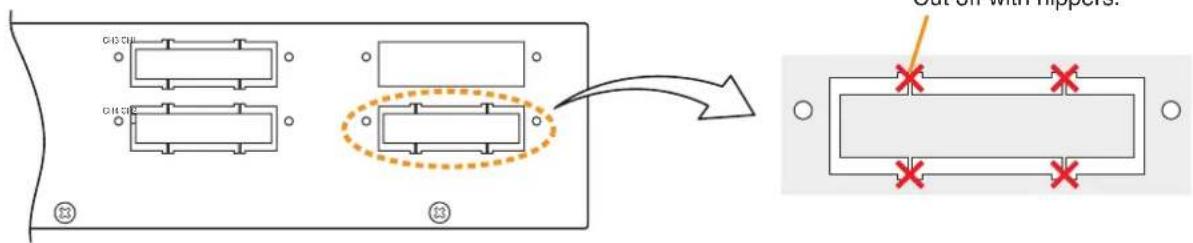
text_image
Cut off with HopperStep 3. Unscrew the VP-200VX's panel.
Step 4. Mount the VP-200VX module.
Attach the VP-200VX's panel to the mounting location and the VP-200VX unit to the back of the mounting location, then secure them to the amplifier using the screws removed in Step. 3.
Notes
- Perform installation for lower mounting locations (CH2 and CH4) first.
- Mount the VP-200VX with its circuit board components faced down.
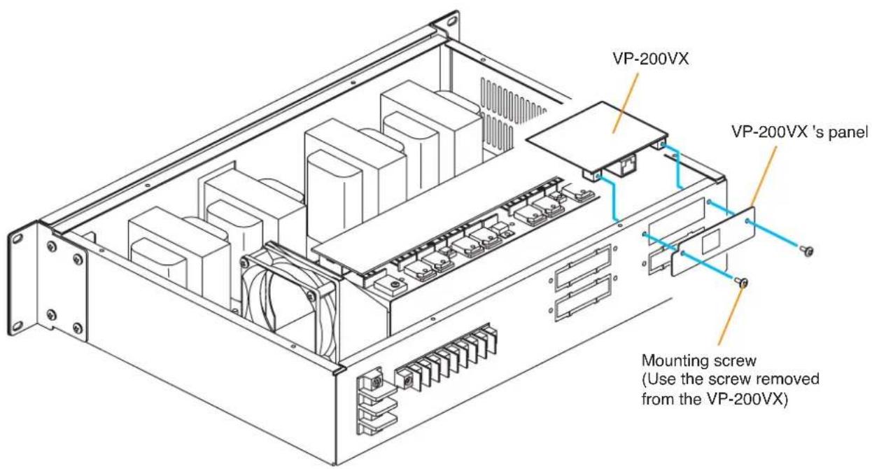
text_image
VP-200VX VP-200VX 's panel Mounting screw (Use the screw removed from the VP-200VX)Step 4. Plug the VP-200VX's connector into the corresponding channel connector on the circuit board inside the amplifier.
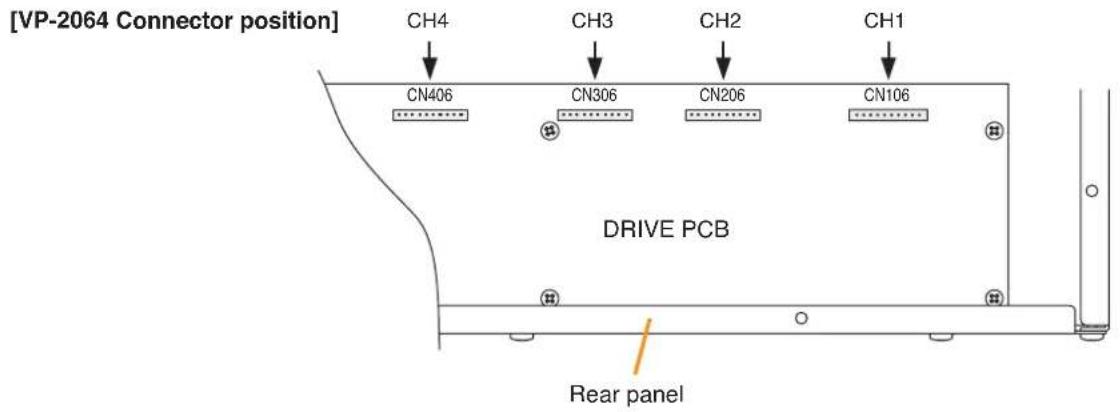
text_image
[VP-2064 Connector position] CH4 CH3 CH2 CH1 CN406 CN306 CN206 CN106 DRIVE PCB Rear panel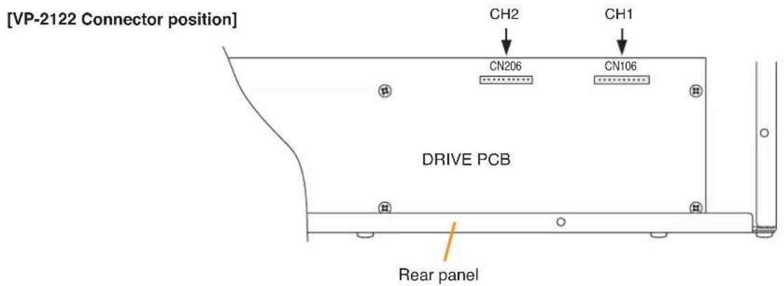
text_image
[VP-2122 Connector position] CH2 CH1 CN206 CN106 DRIVE PCB Rear panel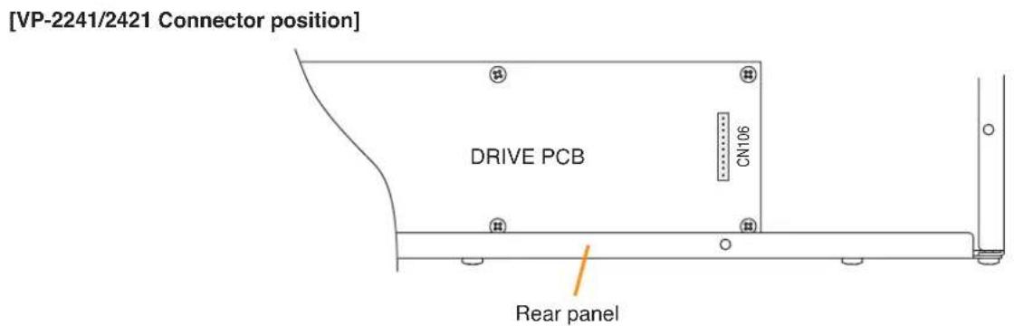
text_image
[VP-2241/2421 Connector position] DRIVE PCB CN106 Rear panel[Channel-to-connector relationship]
| Model No. VP-2064 VP-2122 VP-2241VP-2421 | |
| Channel 1 CN106 CN106CN106 CN106 | |
| Channel 2 CN206 CN206 | — — |
| Channel 3 CN306 | — — |
| Channel 4 CN406 | — — |
Step 5. After mounting is completed for all required channels, replace the top panel.
2.6.4. Ground lifting using the VP-200VX Power Amplifier Input Module
When operating the system, hum noise may be generated by a ground loop accidentally created in the system. The ground loop can be cut off with the Ground Lift jumper connector setting on the VP-200VX board.

WARNING
To access the Ground Lift jumper connector, take out the internal VP-200VX from the VP amplifier. Make sure that the system power is switched OFF before starting the work.
For procedures regarding switching off the system power, refer to the Instruction Manual attached to the VX-2000DS.
Step 1. Remove the VP amplifier's top panel.
Refer to p. 87 "Removing the VP Power Amplifier's top panel."
Step 2. Take out the VP-200VX.
Step 3. Unplug the jumper socket and plug it to the LIFT position on the VP-200VX board as shown below.
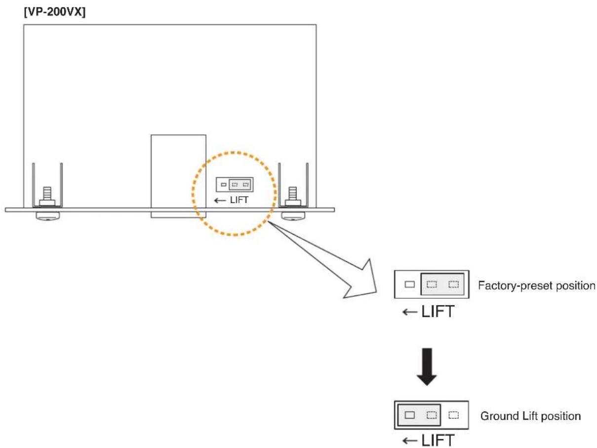
text_image
[VP-200VX] ← LIFT ← Factory-preset position ← LIFT ↓ Ground Lift position ← LIFTStep 4. Fit the VP-200VX back into place.
Step 5. Replace the top panel.
2.6.5. Replacing the blade fuse
When the internal blade fuse blew, replace it with new one following the procedures below.

WARNING
Be sure to switch off the system power before accessing to the internal fuse for replacement. For the method to switch off the power, refer to the Instruction Manual attached to the VX-2000DS.
Step 1. Remove the VP amplifier's top panel.
Refer to p. 87 "Removing the VP Power Amplifier's top panel."
Step 2. Replace the Blade fuse.
Capacity
VP-2064: Blade-Type Fuse 7.5 A
VP-2122: Blade-Type Fuse 15 A
VP-2241: Blade-Type Fuse 25 A
VP-2421: Blade-Type Fuse 35 A
[VP-2064 Blade fuse position]
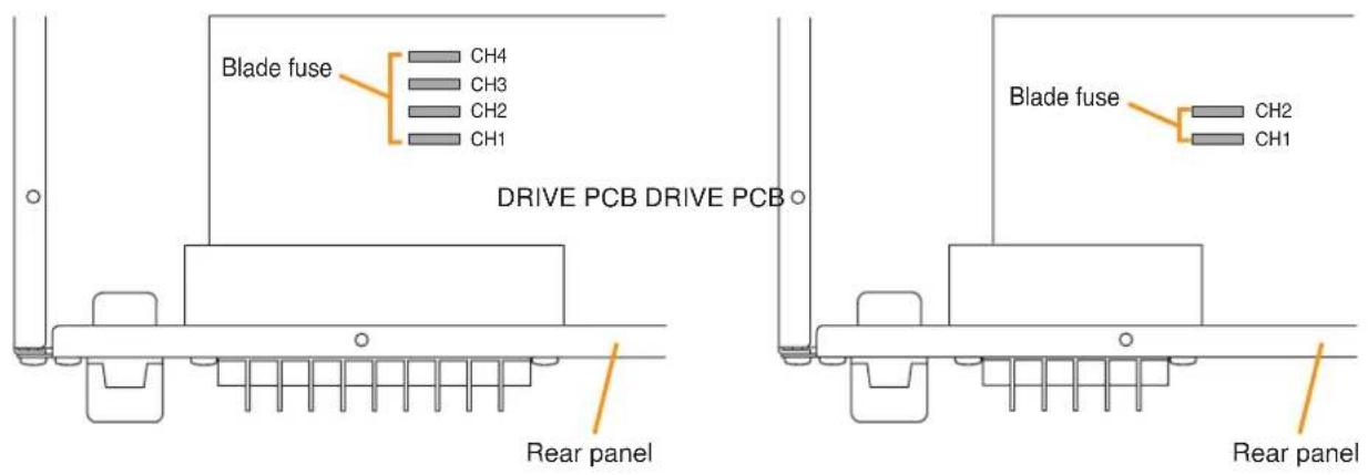
text_image
Blade fuse CH4 CH3 CH2 CH1 DRIVE PCB DRIVE PCB Rear panel Blade fuse CH2 CH1 Rear panel[VP-2122 Blade fuse position]
[VP-2241/2421 Blade fuse position]

text_image
Blade fuse DRIVE PCB Rear panelNote
After completing the replacement of the fuse, remove the cause of fuse blowout before turning on the system power.
2.7. Rack Mounting

CAUTION
The supplied rack-mounting screws can be used for the TOA equipment rack only. Do not use them for other racks.
Failure to do so may cause personal injury.
Note
Because the VP amplifiers, VX-2000DS, and VX-2000PF are heavy, use supporting runners (separately prepared) in the rack to safely mount and securely support the units.
[Mounting power amplifiers]
- Mount the power amplifier as high as possible in the rack.
- Mount the perforated panels in place of space to ensure ventilation.
[Mounting the blower unit]
It is recommended that a blower unit be installed at the uppermost position for efficient exhaust of inner heated air.
![TOA D-921F - [Mounting the blower unit] - 1](/content/2026/06/1214100/images/6a946d599defd3d6daebeb2c31266595d3cd2459b3a3ca6d9671dee2ce745fc2.jpg)
text_image
1 PF-013B 2 Power amplifier 3 PF-013B 4 Power amplifier 5 Power amplifier 6 Power amplifier 7 Power amplifier 8 PF-013B 9 SX-2000CI 10 SX-2000CO 11 SX-2100AO 12 SX-2100AO 13 SX-2000SM 14 SX-2100AI 15 SX-2000AI 16 SX-2000SM 17 SX-2100AI 18 SX-2000AI 19 SX-2000AI 20 VX-2000PF 21 22 23 24 PF-013B 25 VX-2000DS 26 PF-013B 27[Mounting the power supply unit]
- Mount a perforated panel above the VX-2000DS to facilitate its internal fuse replacement because fuse can be accessed through the rear most section of the top panel.
- When batteries are installed in the rack, place them directly below the VX-2000DS so that they can perform temperature compensation for the charging voltage.
In this case, use a perforated panel in front of the rack to avoid excessive temperature rise around the batteries.
[Mounting SX-2000SM, SX-2000AI, SX-2100AI, SX-2000AO, SX-2100AO, SX-2000CI, and SX-2000CO]
• These units have no restriction to use of perforated panels and supporting runners.
- Mount these units below power amplifiers or other heat generating equipment, and at the position for easy operation and easy connection to peripheral equipment.
3. SYSTEM CONFIGURATION EXAMPLE
3.1. System Configuration Example 1
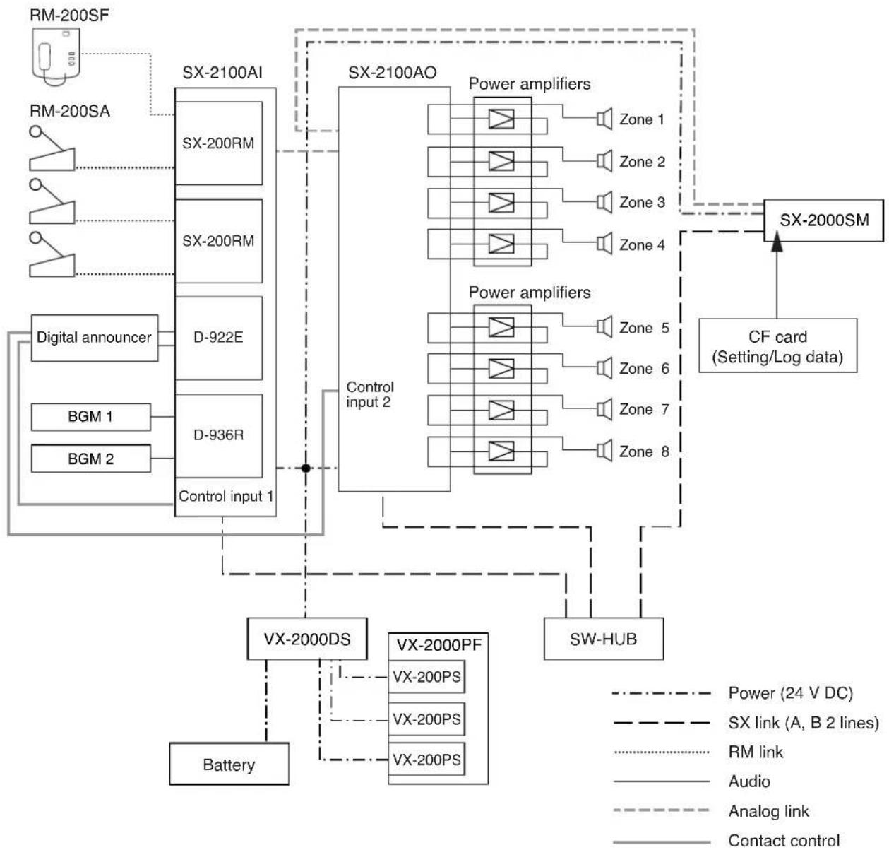
flowchart
graph TD
    A["RM-200SF"] --> B["SX-2100AI"]
    C["RM-200SA"] --> B
    D["Digital announcer"] --> E["D-922E"]
    F["BGM 1"] --> G["D-936R"]
    H["BGM 2"] --> G
    I["Battery"] --> J["VX-2000DS"]
    K["VX-200PF"] --> L["VX-200PS"]
    K --> M["VX-200PS"]
    K --> N["VX-200PS"]
    O["Control input 1"] --> P["Control input 2"]
    Q["Power amplifiers"] --> R["Zone 1"]
    Q --> S["Zone 2"]
    Q --> T["Zone 3"]
    Q --> U["Zone 4"]
    V["Power amplifiers"] --> W["Zone 5"]
    V --> X["Zone 6"]
    V --> Y["Zone 7"]
    V --> Z["Zone 8"]
    AA["SW-HUB"] --> AB["Switch SM"]
    AC["CF card (Setting/Log data)"] --> AD["Switch SM"]
    AE["Power (24 V DC)"] -.-> AF["Switch SM"]
    AG["SX link (A, B 2 lines)"] -.-> AH["Switch SM"]
    AI["RM link"] -.-> AJ["Switch SM"]
    AK["Audio"] -.-> AL["Switch SM"]
    AM["Analog link"] -.-> AN["Switch SM"]
    AO["Contact control"] -.-> AP["Switch SM"]
[Components]
RM-200SF: Fireman's microphone
RM-200SA: Remote microphone
SX-2100AI: Audio input unit
SX-200RM: Remote microphone interface module
D-922E: Microphone/Line input module
D-936R: Stereo input module
SX-2100AO: Audio output unit
SX-2000SM: System manager
VX-2000DS: Emergency power supply
VX-200PS: Power supply unit
VX-2000PF: Power supply frame
3.2. System Configuration Example 2

flowchart
graph TD
    A["Programable Timer"] --> B["Programable Timer"]
    B --> C["Power Amplifiers"]
    C --> D["Control input"]
    D --> E["VX-2000DS"]
    E --> F["Battery"]
    F --> G["VX-2000PS"]
    G --> H["Battery"]
    H --> I["VX-2000PS"]
    I --> J["VX-2000PS"]
    J --> K["Battery"]
    K --> L["VX-2000DS"]
    L --> M["Battery"]
    M --> N["VX-2000PS"]
    N --> O["Battery"]
    O --> P["VX-2000PS"]
    P --> Q["Battery"]
    Q --> R["VX-2000PS"]
    R --> S["Battery"]
    S --> T["VX-2000DS"]
    T --> U["Battery"]
    U --> V["VX-2000PS"]
    V --> W["Battery"]
    W --> X["VX-2000PS"]
    X --> Y["Battery"]
    Y --> Z["VX-2000PS"]
    Z --> AA["Battery"]
    AA --> AB["VX-2000PS"]
    AB --> AC["Battery"]
    AC --> AD["VX-2000PS"]
    AD --> AE["Battery"]
    AE --> AF["VX-2000PS"]
    AF --> AG["Battery"]
    AG --> AH["VX-2000PS"]
    AH --> AI["Battery"]
    AI --> AJ["VX-2000PS"]
    AJ --> AK["Battery"]
    AK --> AL["VX-2000PS"]
    AL --> AM["Battery"]
    AM --> AN["VX-2000PS"]
    AN --> AO["Battery"]
    AO --> AP["VX-2000PS"]
    AP --> AQ["Battery"]
    AQ --> AR["VX-2000PS"]
    AR --> AS["Battery"]
    AS --> AT["VX-2000PS"]
    AT --> AU["Battery"]
    AU --> AV["VX-2000PS"]
    AV --> AW["Battery"]
    AW --> AX["VX-2000PS"]
    AX --> AY["Battery"]
    AY --> AZ["VX-2000PS"]
    AZ --> BA["Battery"]
    BA --> BB["VX-2000PS"]
    BB --> BC["Battery"]
    BC --> BD["VX-2000PS"]
    BD --> BE["Battery"]
    BE --> BF["VX-2000PS"]
    BF --> BG["Battery"]
    BG --> BH["VX-2000PS"]
    BH --> BI["Battery"]
    BI --> BJ["VX-2000PS"]
    BJ --> BK["Battery"]
    BK --> BL["VX-2000PS"]
    BL --> BM["Battery"]
    BM --> BN["VX-2000PS"]
    BN --> BO["Battery"]
    BO --> BP["VX-2000PS"]
    BP --> BQ["Battery"]
    BQ --> BR["VX-2000PS"]
    BR --> BS["Battery"]
    BS --> BT["VX-2000PS"]
    BT --> BU["Battery"]
    BU --> BV["VX-2000PS"]
    BV --> BW["Battery"]
    BW --> BX["VX-2000PS"]
    BX --> BY["Battery"]
    BY --> BZ["VX-2000PS"]
    BZ --> CA["Battery"]
    CA --> CB["VX-2000PS"]
    CB --> CC["Battery"]
    CC --> CD["VX-2000PS"]
    CD --> CE["Battery"]
    CE --> CF["VX-2000PS"]
    CF --> CG["Battery"]
    CG --> CH["VX-2000PS"]
    CH --> CI["Battery"]
    CI --> CJ["VX-2000PS"]
    CJ --> CK["Battery"]
    CK --> CL["VX-2000PS"]
    CL --> CM["Battery"]
    CM --> CN["VX-2000PS"]
    CN --> CO["Battery"]
    CO --> CP["VX-2000PS"]
    CP --> CQ["Battery"]
    CQ --> CR["VX-2000PS"]
    CR --> CS["Battery"]
    CS --> CT["VX-2000PS"]
    CT --> CU["Battery"]
    CU --> CV["VX-2000PS"]
    CV --> CW["Battery"]
    CW --> CX["VX-2000PS"]
    CX --> CY["Battery"]
    CY --> CZ["VX-2000PS"]
    CZ --> DA["Battery"]
    DA --> DB["VX-2000PS"]
    DB --> DC["Battery"]
[Components]
RM-200SF: Fireman's microphone
RM-200SA: Remote microphone
RM-200RJ: Terminal unit
AD-246: AC adapter
SX-2000AI: Audio input unit
SX-2100AI: Audio input unit
SX-200RM: Remote microphone interface module
SX-2000Cl: Control input unit
D-922E: Microphone/Line input module
D-936R: Stereo input module
SX-2000AO: Audio output unit
SX-2100AO: Audio output unit
SX-2000SM: System manager
SX-2000CO: Control output unit
VX-2000DS: Emergency power supply
VX-200PS: Power supply unit
VX-2000PF: Power supply frame
4. CONNECTIONS
4.1. Removable Terminal Plug Connection
Notes
- Use the screwdriver supplied with the SX-2000SM when connecting the removable terminal connector.
- Do not use a micro screwdriver. Sufficient torque is not given to the screws when tightening them, and connections may not be secured.
- Avoid soldering stranded or shielded cable, as contact resistance may increase when the cable is tightened and the solder is crushed, possibly resulting in an excessive rise in joint temperatures.
- When connecting 2 cables or a shielded cable to a single terminal, use a ferrule terminal with an insulation sleeve to crimp the cables because such cable conductors could become loose.
Recommended ferrule terminals for signal cables (made by Phoenix Contact)
| Model Number a I | b | 1 | I2 | ||
| 1 | AI 0,34-8 TQ | 2 mm | 0.8 mm | 12.5 mm | 8 mm |
| 2 | AI 0,5-8 WH | 2.5 mm | 1.1 mm | 14 mm | 8 mm |
Recommended ferrule terminals for power supply cables (made by Phoenix Contact)
| Model Number a | a | 1 | a2 | b | l1 | l2 | |
| 3 | AI 1,5-8 BK | 3.4 mm | — | — | 1.8 mm | 14 mm | 8 mm |
| 4 | AI-TWIN 2 x 1,5-8 BK | 6.6 mm | 3.6 mm | 16 mm2 | 8 mm |
Crimping tool: CRIMPFOX UD6-4 (made by Phoenix Contact)
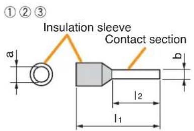
text_image
①②③ Insulation sleeve Contact section a b l₂ l₁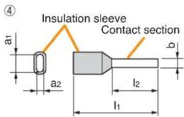
text_image
Insulation sleeve Contact section a1 a2 b l2 l1Cable sheath to trim
Solid cable and stranded cable Shielded cable


text_image
15 mm* Expose 8 mm or more when using the above ferrule terminal, and cut off an extra conductor protruding from the sleeve.
Wiring procedures
Procedures below are for the removable terminal plug with fixing screws.
Step 1. Wiring the supplied removable terminal plug.
1-1. Loosen the terminal screws to insert the wire.
1-2. Tighten the terminal screws.
Ensure that the wire does not break free when pulled.
If the wire does pull free, repeat the connection procedure from the start.
Step 2. Insert the wired terminal plug into the corresponding terminal block in the unit's rear panel.
Step 3. Tighten the fixing screw.

text_image
Screwdriver (supplied with the SX-2000SM) To tighten To loosen Terminal screw Removable terminal plug Fixing screwNotes
- Do not reverse Steps 1 and 2 above. Force is applied to the connected receptacle pins while tightening the terminal screw and they may be damaged, resulting in bad connector contact.
- When detaching the terminal plug, pull it straight out. Pulling it out at an angle may cause the terminal plug or terminal block to break.
4.2. Input Equipment Connections
4.2.1. Connections of SX-2100AO's Local audio control input terminals
Use STP Category 5 straight cables for connections.
The diagram below shows cable connections to the Local audio control input terminal.

flowchart
graph TD
    A["SX-2100AO"] --> B["Local audio control input terminals"]
    B --> C["Local audio control input terminals (RJ45)"]
    C --> D["Photo coupler"]
    D --> E["Internal circuit"]
    style A fill:#f9f,stroke:#333
    style B fill:#ccf,stroke:#333
    style C fill:#cfc,stroke:#333
    style D fill:#fcc,stroke:#333
    style E fill:#ffc,stroke:#333
    note right of C: Note for wiring when a change is made to use an external power supply, refer to p. 61.
    note right of D: Photo coupler connected to VCC via 4.4 kΩ resistor
    note right of E: External power source connected to Sound source via 8 pins
| Signal Type | RJ45 connector pin No. | Cable color (T568B type) | Cable color (T568A type) | Remarks |
| — | 1 | Orange/White | Green/White | Not used |
| — | 2 | Orange | Green | Not used |
| Control IN | 3 | Green/White | Orange/White | Connect to the external device's control output terminal*1 (positive polarity). |
| Audio input (H) | 4 | Blue | Blue | Connect to the external device's audio signal*2 (hot). |
| Audio input (C) | 5 | Blue/White | Blue/White | Connect to the external device's audio signal*2 (common). |
| External power source | 6 | Green | Orange | Power input terminal from external power supply for control input *3 |
| — | 7 | Brown/White | Brown/White | Not used |
| GND | 8 | Brown | Brown | Connect to the external device's control output terminal (negative polarity). |
| SHIELD | — | — | — | Connect to the external device's audio signal ground*2. |
*1 Specifications of the control input are as follows.
2 inputs, no-voltage make contact input, open voltage: 12 V DC, short-circuit current: 2 mA, photo cuppler input
^*2 Specifications of the audio input are as follows.
0 dB, 10 kΩ, electrically-balanced input
Do not connect a microphone having no preamplifier directly to the SX-2100AO. To enable the connection, use a preamplifier between the microphone and SX-2100AO.
*3 Refer to p. 61 for isolating the control input by using external power supply.
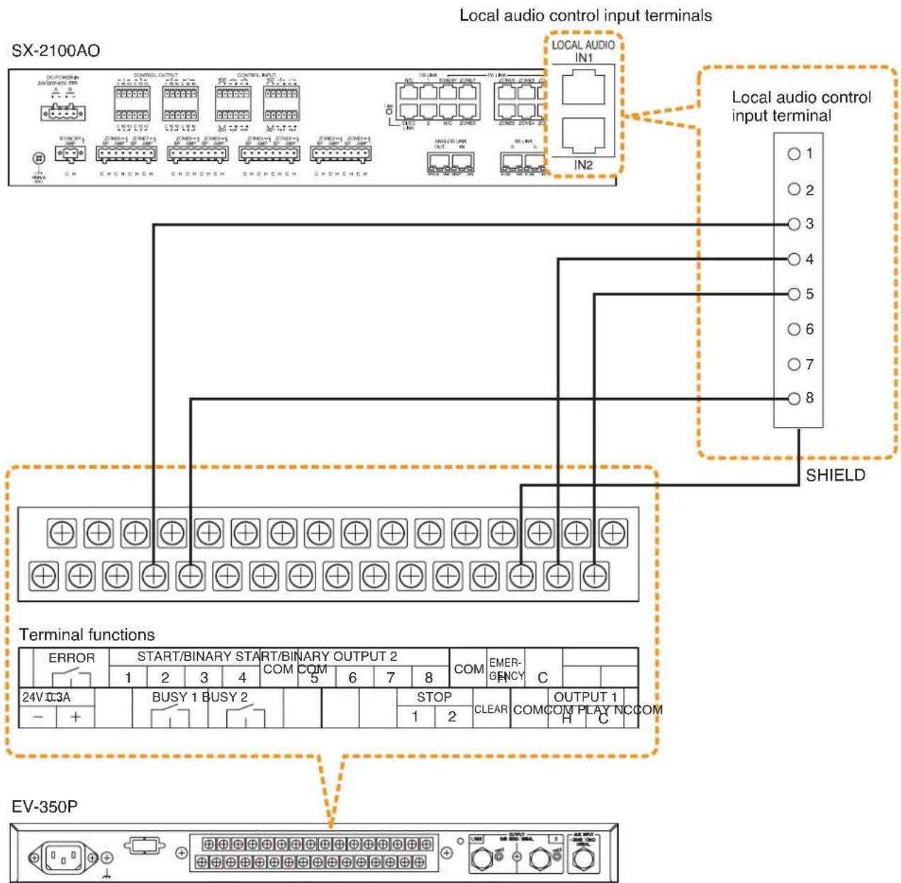
text_image
SX-2100AO Local audio control input terminals LOCAL AUDIO IN1 LOCAL AUDIO input terminal SHIELD Terminal functions ERROR START/BINARY START/BINARY OUTPUT 2 COM COM EMER- C 1 2 3 4 5 6 7 8 24V DC3A BUSY 1 BUSY 2 STOP CLEAR OUTPUT 1 COM COM PLAY NCCOM H C EV-350P4.2.2. Connecting the SX-200RM to the RM-200SF or RM-200SA (via RM-200RJ as needed)
Connect the RM Link terminal of the SX-200RM unit mounted in the SX-2000AI or SX-2100AI to the terminal block of the RM-200SF or the RM LINK terminal of the RM-200SA. The length of the connection cable differs depending on the method of power supply and the type of cable used.
Note
Connect the RM-200SF or RM-200SA individually to each input of the SX-200RM mounted in the SX-2000AI or SX-2100AI.
The input channel to which the RM-200SF or RM-200SA can be connected is assigned by the SX-2000 Setting Software and indicated by the orange RM1 or RM2 status indicator. Connect the RM-200SF or RM-200SA assigned the same device number as the SX-2000AI's or SX-2100AI's input channel number to the RM LINK terminal.
(For the RM-200SF and RM-200SA device number settings, see p. 64.)
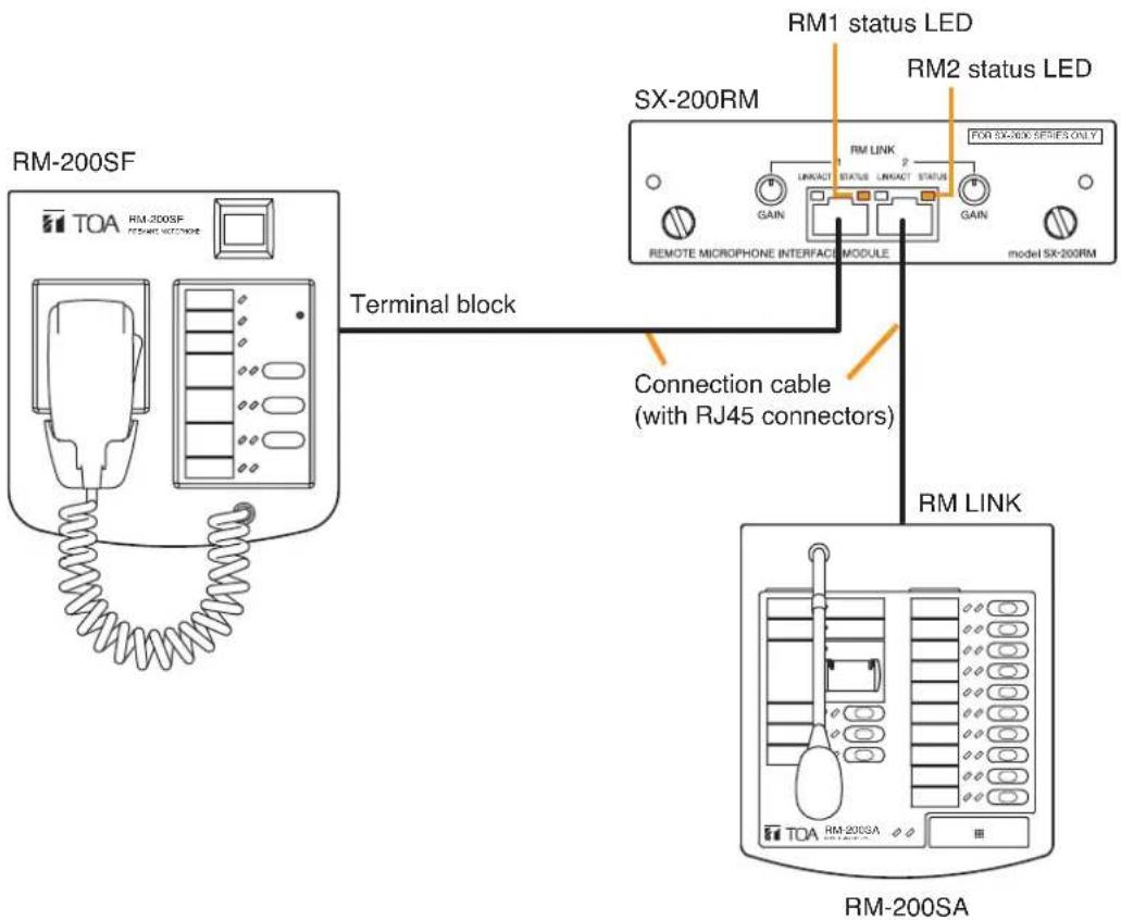
text_image
RM-200SF TOA RM-200SF FOR 5X-NOX SERIES ONLY Terminal block RM1 status LED RM2 status LED SX-200RM GAIN LINKACT STATUS LINKACT STATUS REMOTE MICROPHONE INTERFACE MODULE FOR SX-NOX SERIES ONLY model SX-200RM Connection cable (with RJ45 connectors) RM LINK TOA RM-200SA RM-200SAConnecting the SX-200RM to the RM-200SF
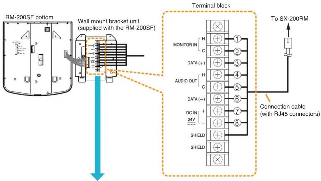
text_image
RM-200SF bottom Wall mount bracket unit (supplied with the RM-200SF) Terminal block MONITOR IN H C DATA (+) H C AUDIO OUT H C DATA (-) H C DC IN + 24V SHIELD SHIELD To SX-200RM Connection cable (with RJ45 connectors)| Wall mount bracket unit(supplied with the RM-200SF) | RJ45 connector pin No. | Cable color(T568B type) | Cable color(T568A type) |
| MONITOR IN (H) | 1 | Orange/White | Green/White |
| MONITOR IN (C) | 2 | Orange | Green |
| DATA (+) | 3 | Green/White | Orange/White |
| AUDIO OUT (H) | 4 | Blue | Blue |
| AUDIO OUT (C) | 5 | Blue/White | Blue/White |
| DATA (-) | 6 | Green | Orange |
| DC IN 24 V (+) | 7 | Brown/White | Brown/White |
| DC IN 24 V (-) | 8 | Brown | Brown |
| SHIELD Shield | — | — |
[When power is supplied from the SX-200RM]
- The following table shows the maximum cable distance when STP Category 5 straight cable (with RJ45 connectors) is used.
| Cable\No. of expansion units | RM-200SF alone | RM-200SF + RM-210 x 1 | RM-200SF + RM-210 x 2 | RM-200SF + RM-210 x 3 | RM-200SF + RM-210 x 4 | RM-200SF + RM-210 x 5 |
| STP Category 5 140 m 120 m | 100 m 90 m 80 | m | 70 m |
• To make longer cable lengths than those shown in the above table, use over 4-pair shielded CPEV cable. The relationship of the CPEV cable conductor diameter to the maximum cable distance is as follows:
| No. of expansion unitsConductor diameter | RM-200SF alone | RM-200SF + RM-210 x 1 | RM-200SF + RM-210 x 2 | RM-200SF + RM-210 x 3 | RM-200SF + RM-210 x 4 | RM-200SF + RM-210 x 5 |
| ø0.65 mm | 230 m 190 | m 170 m 150 m | 130 m | 110 m | ||
| ø0.9 mm | 460m 380 | m 330 m 290 m | 260 m | 230 m | ||
| ø1.2 mm | 800 m 670 | m 570 m 500 m | 450 m | 400 m |
Connecting the SX-200RM to the RM-200SA
![TOA D-921F - [When power is supplied from the SX-200RM] - 1](/content/2026/06/1214100/images/b246efa0f168ddc53e584f962e6dbb90c01e2d5352eefe1c41e7a27a5064f2dd.jpg)
text_image
RM-200SA rear SCROMETER 340Ω RM LINK MC EXTERNAL MCM Connection cable (with RJ45 connectors) To SX-200RM[When power is supplied from the SX-200RM]
- The following table shows the maximum cable distance when STP Category 5 straight cable (with RJ45 connectors) is used.
| Cable\No. of expansion units | RM-200SA alone | RM-200SA + RM-210 x 1 | RM-200SA + RM-210 x 2 | RM-200SA + RM-210 x 3 | RM-200SA + RM-210 x 4 |
| STP Category 5 140 m 120 m | 100 m 90 m 80 m |
- To make longer cable lengths than those shown in the above table, use over 4-pair shielded CPEV cable. (For the cable connection, see below.)
The relationship of the CPEV cable conductor diameter to the maximum cable distance is as follows:
| No. of expansion unitsConductor diameter | RM-200SA alone | RM-200SA + RM-210 x 1 | RM-200SA + RM-210 x 2 | RM-200SA + RM-210 x 3 | RM-200SA + RM-210 x 4 |
| ø0.65 mm | 230 m 190 m | 170 m 150 m | 130 m | ||
| ø0.9 mm | 460m 380 m | 330 m 290 m | 260 m | ||
| ø1.2 mm | 800 m 670 m | 570 m 500 m | 450 m |
- When using a shielded CPEV cable, it is recommended to use an optional RM-200RJ Terminal Unit that serves wiring conversion between the CPEV cable and STP Category 5 straight cable (with RJ45 connectors). Connect the CPEV cable between the same terminals of both RM-200RJ units pairing cables 1 with 2, 4 with 5, 3 with 6, and 7 with 8 as shown below.
![TOA D-921F - [When power is supplied from the SX-200RM] - 1](/content/2026/06/1214100/images/fe41ada919216760acdbf233da6a11a2d8367148c8a5d2a14113da6959695e9c.jpg)
text_image
SX-200RM RM-200RJ TOA STP Category 5 straight cable (with RJ45 connectors) RM-200SA rear RM-200RJ Over 4-pair shielded CPEV cable (main cable) STP Category 5 straight cable (with RJ45 connectors) RM LINK TERMINAL UNIT RM-200RJ RM LINK DC MONITOR TERMINAL UNIT RM-200RJ RM LINK DC MONITOR TERMINAL UNIT RM-200RJ RM LINK DC MONITOR TERMINAL UNIT RM-200RJ RM LINK DC MONITOR TERMINAL UNIT RM-200RJ RM LINK DC MONITOR TERMINAL UNIT RM-200RJ RM LINK DC MONITOR TERMINAL Unit RM-200RJ RM LINK DC MONITOR TERMINAL Unit RM-200RJ RM LINK DC MONITOR TERMINAL Unit RM-200RJ RM LINK DC MONITOR TERMINAL Unit RM-200RJ[RM-200RJ Mounting dimensions]
![TOA D-921F - [When power is supplied from the SX-200RM] - 2](/content/2026/06/1214100/images/ba8c563df35d6aa01ca59602f05753eee90c46755bc328cc89bd136f43ec5d9f.jpg)
text_image
84 75 116 44.5 44.513.5Note
The RM-200RJ can be installed on a desk or to a wall.
- When using a shielded CPEV cable but not the RM-200RJ, connect the cable to STP Category 5 straight cable (with RJ45 connectors) as follows. Pair 1 with 2, 3 with 6, 4 with 5, and 7 with 8.
![TOA D-921F - [When power is supplied from the SX-200RM] - 3](/content/2026/06/1214100/images/7de5f04ed7a897ce337ac5b91adc334645ee1542346e524286f4fe1799a9f7f1.jpg)
flowchart
graph LR
    A["To RM-200SA"] --> B["RJ45 connector pin No. 1-8"]
    B --> C["Over 4-pair shielded CPEV cable (main cable)"]
    C --> D["RJ45 connector pin No. 1-8"]
    D --> E["STP Category 5 straight cable (with an RJ45 connector)"]
    E --> F["Shield"]
    F --> G["To SX-200RM"]
    style A fill:#f9f,stroke:#333
    style B fill:#ccf,stroke:#333
    style C fill:#cfc,stroke:#333
    style D fill:#fcc,stroke:#333
    style E fill:#cff,stroke:#333
    style F fill:#ffc,stroke:#333
    style G fill:#cfc,stroke:#333
| RM-200SA | RJ45 connector pin No. | Cable color (T568B type) | Cable color (T568A type) | SX-200RM |
| Monitor in (H) | 1 | Orange/White | Green/White | Monitor out (H) |
| Monitor in (C) | 2 | Orange | Green | Monitor out (C) |
| RM data | 3 | Green/White | Orange/White | RM data |
| Audio out (H) | 4 | Blue | Blue | Audio in (H) |
| Audio out (C) | 5 | Blue/White | Blue/White | Audio in (C) |
| RM data | 6 | Green | Orange | RM data |
| DC power in (+) | 7 | Brown/White | Brown/White | DC power out (+) |
| DC power in (-) | 8 | Brown | Brown | DC power out (-) |
| Shield Shield | — | — | Shield |
[When supplying power from the AC adapter]
When supplying power to the RM-200SA from the optional AD-246 AC Adapter using the cables listed in the tables on p. 101, the maximum length of connection cable (main line) is 800 m regardless of the type of cable and the number of remote microphone expansion units.
Note
To power the remote microphones even during power failures, a battery backup is also needed for the AC adapter.
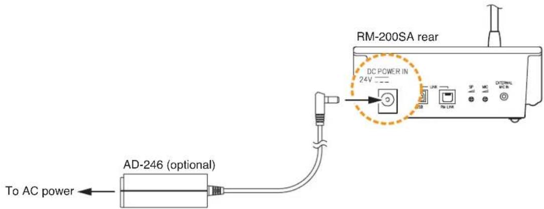
text_image
RM-200SA rear DC POWER IN 24V AD-246 (optional) To AC power4.2.3. Connecting other input equipment
Connect input equipment to the following modules installed in the SX-2000AI or SX-2100AI.
[Microphone/Line Input Modules D-921F and D-922F]
Connect microphones or other sound sources with line outputs using 2-core shielded cables.
![TOA D-921F - [Microphone/Line Input Modules D-921F and D-922F] - 1](/content/2026/06/1214100/images/dee4e2a817d7ab4c01353922f8b2baa4ab9082a030c736d4287f5511e474c438.jpg)
text_image
MICA LINE INPUT MODULE [50 / -36 / -10 / +4 dB] model D-921F AUC 200V 11:00K![TOA D-921F - [Microphone/Line Input Modules D-921F and D-922F] - 2](/content/2026/06/1214100/images/f6dc458528618d409f75089cc1f862bdad658e19224ac95cfe0cd2efa56fa154.jpg)
text_image
MICRINE INPUT MODULE MODEL 15-322F ACCESSOPY-TE-90X[Microphone/Line Input Modules D-921E and D-922E]
Connect microphones or other sound sources with line outputs using 2-core shielded cables. Use the supplied 3-pin removable terminal plug for connection.
![TOA D-921F - [Microphone/Line Input Modules D-921E and D-922E] - 1](/content/2026/06/1214100/images/10df6ba5e5b5839524e02448bb1d2c1c9fa92ccf77795b227d9f1351a905e56f.jpg)
text_image
MIDLINE INPUT MODULE [50 / 38 / -10 / +4 dB] model D-921E![TOA D-921F - [Microphone/Line Input Modules D-921E and D-922E] - 2](/content/2026/06/1214100/images/15b80069bb67da993297f48a21b7717dca584157294af64d40691dac66541081.jpg)
text_image
MIC/LINE INPUT MODULE model D 922E[Stereo Input Module D-936R]
Connect BGM players or other sound sources to this module.
![TOA D-921F - [Stereo Input Module D-936R] - 1](/content/2026/06/1214100/images/eeb9742e5bf626a249b4740b43ffadd1eb0e4dcd1d05f5a80165cb21e59e5d2b.jpg)
text_image
Monaural input 1 Monaural input 2 model D-936RSTREO SELECT INPUT MODULE [-10 dB]Note
Since this module is equipped with 2 monaural input channels, connect a different sound source to each input. When using a stereo sound source, convert the stereo output to monaural first and connect it to one of the two inputs. Input terminals 1L – 4L of Monaural input 1 are connected in parallel inside the module. Similarly, input terminals 1R – 4R of Monaural input 2 are internally parallel-connected.
- When separately using the L and R channels of sound source equipment, make connections as follows.
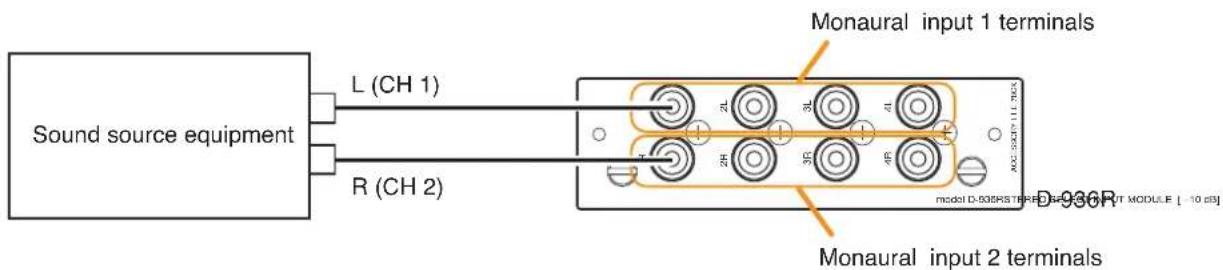
text_image
Sound source equipment L (CH 1) R (CH 2) Monaural input 1 terminals Monaural input 2 terminals model D-935RSTFRE0 ENOAL INPUT MODULE [ -10 dB]- When using the sound source's L and R channels as one channel, make connections as follows. However, the input signal level tends to be extremely large in this case, so adjust the input level with care. (Connect the sound source equipment 1's L and R to Monaural input 1 terminals, and the sound source equipment 2's L and R to Monaural input 2 terminals.)
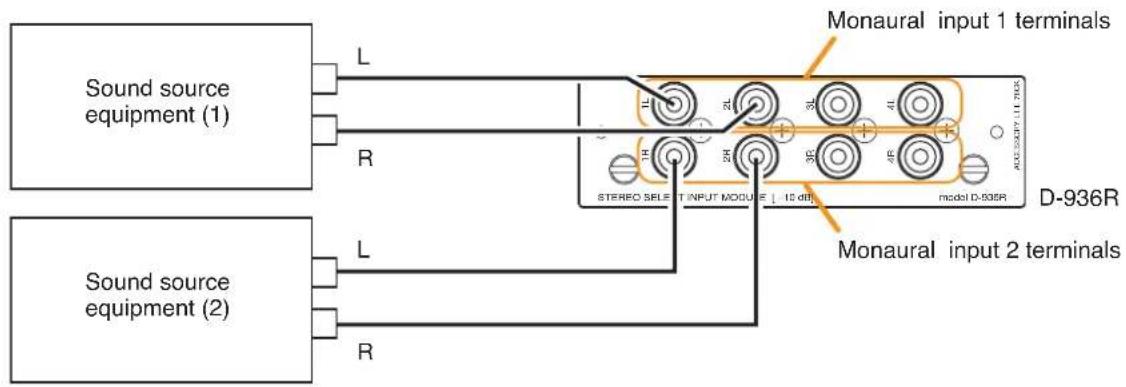
text_image
Sound source equipment (1) L Monaural input 1 terminals R STEREO SELECT INPUT MODULE [ 10 dB ] model D-936R D-936R Sound source equipment (2) L Monaural input 2 terminals R4.3. Output Equipment Connections
4.3.1. Connecting the SX-2000AO to power amplifiers
Connect each output channel (broadcast zone) to the corresponding power amplifier.

text_image
SX-2000AO DC POWER IN CONTROL OUTPUT CONTROL INPUT LINE OUTPUT CREO LINK EMERGENCY LINE OUTPUT ENERGY OUTPUT SINIC OUTPUT ANALOG LINK OUT IN EXLINK Audio output terminals Audio lines (2-core shielded cables) To each channel's assigned power amplifier LINE OUTPUT 4 E C H 3 E C H 2 E C H 1 E C H 12P removable terminal plug (supplied with the SX-2000AO) E C H E C H E C H E C H E C H 8 E C H 7 E C H 6 E C H 5 E C H To each channel's assigned power amplifierIf the power amplifier to be connected is VP-2064, VP-2122, VP-2241, or VP-2421, the VP-200VX Power Amplifier Input Module is used as an interface between the amplifier and the SX-2000AO. For cable connections, refer to the table below.
| SX-2000AO's LINE OUTPUT | VP-200VX's RJ45 connector pin |
| H | Pin 1 (Signal +) |
| C | Pin 2 (Signal -) |
| E | Shield |
Note: Do not connect any cable to the unused pins of RJ45.
4.3.2. Connecting the SX-2100AO to power amplifiers and speakers
Connect each output channel (broadcast zone) to the corresponding power amplifier, and connect the power amplifier's output to the SX-2100AO's amplifier input terminal, then connect speakers to the SX-2100AO's speaker output terminal.
[Connection example: When connecting the VP-2064 to the ZONE 1]
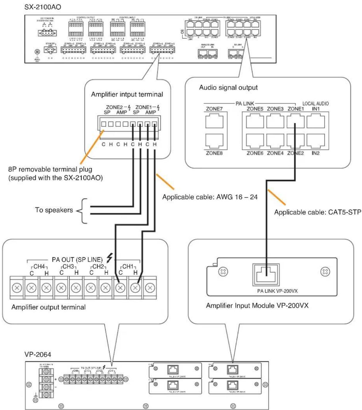
flowchart
graph TD
    A["SX-2100AO"] --> B["Amplifier input terminal"]
    B --> C["8P removable terminal plug (supplied with the SX-2100AO)"]
    B --> D["Audio signal output"]
    D --> E["Amplifier output terminal"]
    E --> F["VP-2064"]

    subgraph Component1
        G["DC/ONEN 3500V/AN 250A"] --> H["CONTROL INPUT"]
        H --> I["CONTROL INPUT1"]
        I --> J["CONTROL INPUT2"]
        J --> K["ZONE1"]
        K --> L["ZONE2"]
        L --> M["ZONE3"]
        M --> N["ZONE4"]
        N --> O["ZONE5"]
        O --> P["VAR"]
        P --> Q["VAR"]
        Q --> R["VAR"]
        R --> S["VAR"]
        S --> T["VAR"]
        T --> U["VAR"]
        U --> V["VAR"]
        V --> W["VAR"]
    end

    subgraph Component2
        X["CH"] --> Y["CH1"]
        Y --> Z["CH2"]
        Z --> AA["CH3"]
        AA --> AB["CH4"]
        AB --> AC["PA OUT (SP LINE)"]
        AC --> AD["To speakers"]
        AD --> AE["8P removable terminal plug (supplied with the SX-2100AO)"]
    end

    subgraph Component3
        AF["DR LINK"] --> AG["VAR"]
        AG --> AH["VAR"]
        AH --> AI["VAR"]
        AI --> AJ["VAR"]
        AJ --> AK["VAR"]
        AK --> AL["VAR"]
        AL --> AM["VAR"]
        AM --> AN["VAR"]
        AN --> AO["VAR"]
        AO --> AP["VAR"]
    end

    subgraph Component4
        AQ["ANALOG LINK"] --> AR["VAR"]
        AR --> AS["VAR"]
        AS --> AT["VAR"]
        AT --> AU["VAR"]
        AU --> AV["VAR"]
        AV --> AW["VAR"]
        AW --> AX["VAR"]
    end

    subgraph Component5
        AY["ZONE7"] --> AZ["TA LINK"]
        AZ --> BA["ZONE5"]
        BA --> BB["ZONE3"]
        BB --> BC["ZONE1"]
        BC --> BD["LOCAL AUDIO IN1"]
        BD --> BE["ZONE8"]
        BE --> BF["TA LINK VP-200VX"]
        BF --> BG["ZONE6"]
        BG --> BH["ZONE4"]
        BH --> BI["ZONE2"]
        BI --> BJ["IN2"]
    end

    subgraph Component6
        BK["PA LINK"] --> BL["ZONE5"]
        BL --> BM["ZONE3"]
        BM --> BN["ZONE1"]
        BN --> BO["LOCAL AUDIO IN1"]
        BO --> BP["ZONE8"]
        BP --> BQ["ZONE6"]
        BQ --> BR["ZONE4"]
        BR --> BS["IN2"]
    end

    subgraph Component7
        BT["PA LINK VP-200VX"] --> BU["TA LINK VP-200VX"]
    end

    subgraph Component8
        BV["PA LINK VP-200VX"] --> BW["TA LINK VP-200VX"]
    end

    subgraph Component9
        BX["PA LINK VP-200VX"] --> BY["TA LINK VP-200VX"]
    end

    subgraph Component10
        BZ["PA LINK VP-200VX"] --> CA["TA LINK VP-200VX"]
    end

    subgraph Component11
        CB["PALINK VP-200VX"] --> CC["TALINK VP-200VX"]
    end

    subgraph Component12
        CD["PALINK VP-200VX"] --> CE["TALINK VP-200VX"]
    end

    subgraph Component13
        CF["PALINK VP-200VX"] --> CG["TALINK VP-200VX"]
    end

    subgraph Component14
        CH["PALINK VP-200VX"] --> CI["TALINK VP-200VX"]
    end

    subgraph Component15
        CJ["PALINK VP-200VX"] --> DA["TALINK VP-200VX"]
    end

    subgraph Component16
        DB["PALINK VP-200VX"] --> DC["TALINK VP-200VX"]
    end

    subgraph Component17
        DD["PALINK VP-200VX"] --> DE["TALINK VP-200VX"]
    end

    subgraph Component18
        DF["PALINK VP-200VX"] --> DG["TALINK VP-200VX"]
    end

    subgraph Component19
        DH["PALINK VP-200VX"] --> DI["TALINK VP-200VX"]
    end

    subgraph Component20
        DJ["PALINK VP-200VX"] --> DE
        DE --> DK["PALINK VP-200VX"]
    end
4.3.3. Connecting the SX-2100AO to external attenuators
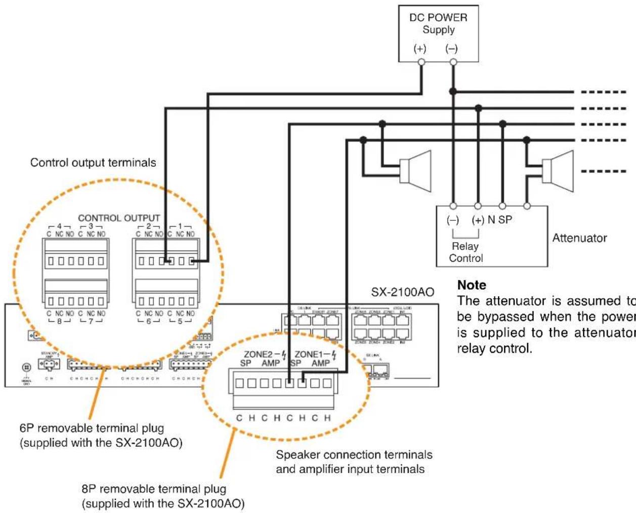
flowchart
graph TD
    A["DC POWER Supply (+) (-)"] --> B["Control output terminals"]
    B --> C["6P removable terminal plug (supplied with the SX-2100AO)"]
    B --> D["8P removable terminal plug (supplied with the SX-2100AO)"]
    B --> E["Speaker connection terminals and amplifier input terminals"]
    C --> F["CONTROL OUTPUT"]
    D --> G["SX-2100AO"]
    E --> H["Attenuator"]
    style A fill:#f9f,stroke:#333
    style B fill:#ccf,stroke:#333
    style C fill:#cfc,stroke:#333
    style D fill:#fcc,stroke:#333
    style E fill:#cff,stroke:#333
    style F fill:#ffc,stroke:#333
    style G fill:#cfc,stroke:#333
    style H fill:#fcc,stroke:#333
[Necessary settings on the SX-2000 Setting Software]
- To use the external attenuators, set the SX-2100AO's "Attenuator" item to "Used" for the corresponding zones in the "System settings" menu. (See the separate Setting Software Instructions, "Audio output settings.")
When set so, the number of zone interlocks with the same number of control output. - These attenuators are bypassed when the system is in emergency broadcast state. To use the emergency broadcast, set the "Emergency" item of "Common settings" to "Used" in the "Basic settings" menu. (See the separate Setting Software Instructions, "Basic settings.")
Note
The speaker line with attenuators installed cannot be detected for its open-circuit state with the Speaker Line Surveillance function.
4.3.4. Connecting the SX-2100AO to standby amplifiers
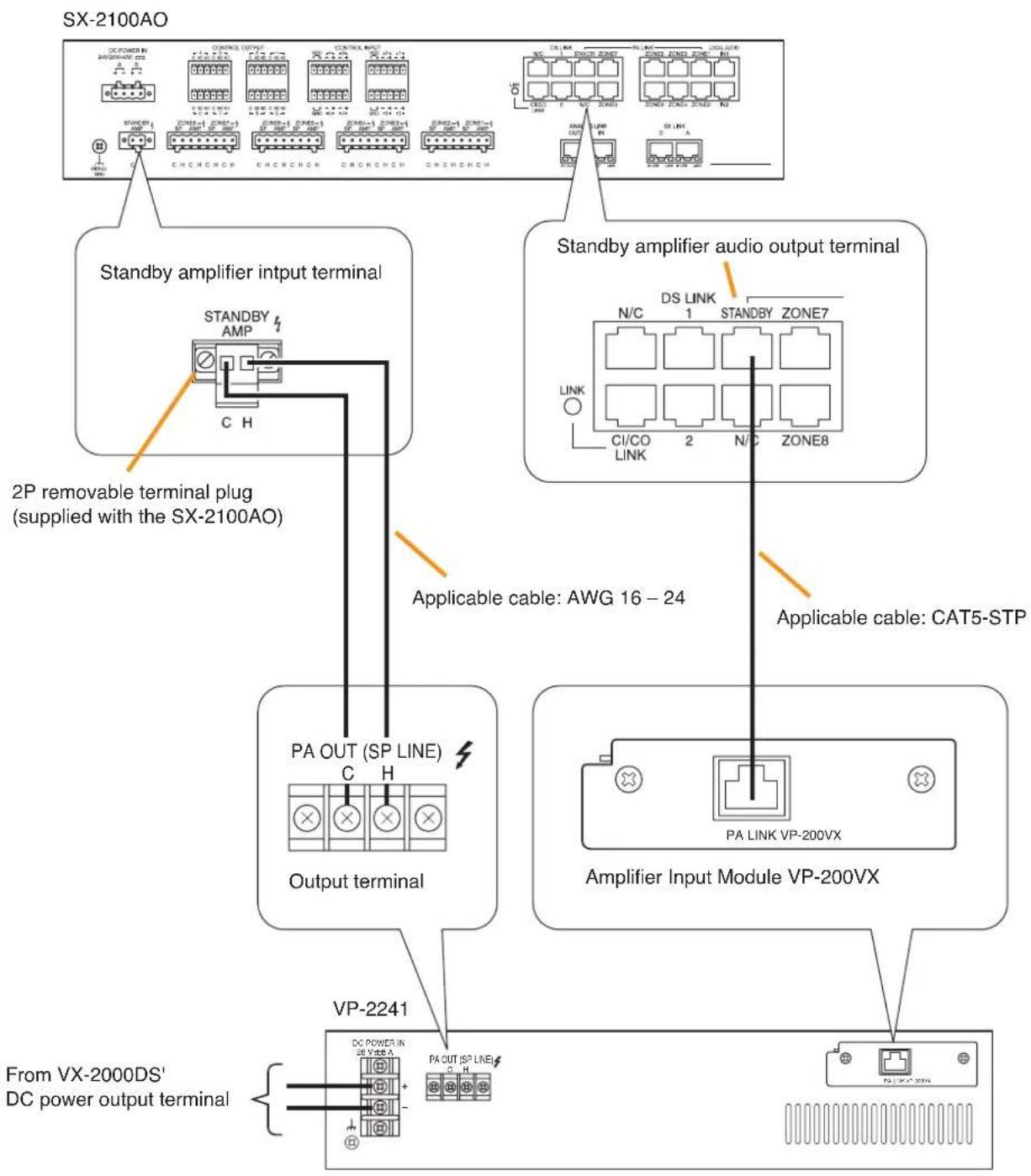
flowchart
graph TD
    A["SX-2100AO"] --> B["Standby amplifier input terminal"]
    A --> C["Standby amplifier audio output terminal"]
    B --> D["2P removable terminal plug (supplied with the SX-2100AO)"]
    C --> E["Output terminal"]
    D --> F["PA OUT (SP LINE)"]
    D --> G["Output terminal"]
    E --> H["Amplifier Input Module VP-200VX"]
    E --> I["From VX-2000DS' DC power output terminal"]
    F --> J["PA OUT (SP LINE)"]
    F --> K["Output terminal"]
    G --> L["Amplifier Input Module VP-200VX"]
    G --> M["From VX-2000DS' DC power output terminal"]
    style A fill:#f9f,stroke:#333
    style B fill:#ccf,stroke:#333
    style C fill:#ccf,stroke:#333
    style D fill:#cfc,stroke:#333
    style E fill:#cfc,stroke:#333
    style F fill:#fcc,stroke:#333
    style G fill:#fcc,stroke:#333
    style H fill:#fcc,stroke:#333
    style I fill:#fcc,stroke:#333
    style J fill:#cff,stroke:#333
    style K fill:#cff,stroke:#333
    style L fill:#cff,stroke:#333
    style M fill:#cff,stroke:#333
Note
To use a standby amplifier, make necessary settings on the SX-2000 Setting Software. (See the separate Setting Software Instructions, "Audio output settings.")
4.4. Control Input/Output Connections
4.4.1. SX-2000SM
[Connecting control input terminals to the TT-104B program timer]
This connection allows timer-activated automatic broadcasts.
When the TT-104B's preprogrammed time is reached, the SX-2000SM receives a control output signal (make contact) from the TT-104B and activates preset broadcast patterns.
![TOA D-921F - [Connecting control input terminals to the TT-104B program timer] - 1](/content/2026/06/1214100/images/f4ae5d47244a32fe1adbc55c0d29b6108c3f1645abf39ca1822054e94ff80301.jpg)
text_image
TT-104B OUTPUT CHANNEL (24 V DC 0.5 A) Cable: AWG22 - 28 twisted pair cable SX-2000SM 12P removable terminal plug (supplied with the SX-2000SM) DC OUT C5 C4 C3 C2 C1 INPUT 24V MAX 0.1A DC POWER IN 24V DC 40V DC DS LINK STATUS OUTPUT 2 LAMP RES ACK C8 C7 C6 Control input terminals Open voltage: 24 V DC Short-circuit current: 2 mA[Connecting control output terminals to the EV-350R Digital Announcer]
This connection remotely activates external connected sound sources.
When a broadcast is started, the SX-2000SM provides a make contact to activate the EV-350R.
![TOA D-921F - [Connecting control output terminals to the EV-350R Digital Announcer] - 1](/content/2026/06/1214100/images/a319daa7874efc028016df296f57da17caa4f65c618ae9ec0e2cab700f6f356a.jpg)
text_image
Withstand voltage: 40 V DC Control current: 2 – 300mA OUTPUT C NC NO C4 C3 C2 C1 C8 C7 C6 C5 12P removable terminal plug (supplied with the SX-2000SM) ANALOG LINK OUT2 OUT1 SX-2000SM Cable: AWG22 – 28 twisted pair cable COM terminal Control output terminals Activation control input terminal 1 EV-350R Activation control input terminal 24.4.2. SX-2100AI
[Connecting control input terminals to the TT-104B program timer]
Since the SX-2100AI's control inputs are photo coupler inputs, they need a power supply. Power can be supplied to the photo couplers using the SX-2100AI's internal power supply or external power supply.
- When using the internal power supply, the power feed jumper and the isolation jumper are needed. Using 16P removable terminal plugs equipped with a jumper, make connections as shown below:
![TOA D-921F - [Connecting control input terminals to the TT-104B program timer] - 1](/content/2026/06/1214100/images/c4a286e51cc0234d78caf8dbd539f7e36e5a7fb1e230e4a0710f4d0cfdcaf459.jpg)
text_image
TT-104B OUTPUT CHANNEL (24 V DC 0.5 A) Cable: AWG22 - 28 twisted pair cable 16P removable terminal plug (supplied with the SX-2100AI) SIX-2100AI Isolation Jumper Power Feed Jumper CONTROL INPUT VCC 8-7 6-5 4 3 2 1 GND 16-15 14-13 12 11 10 9 Control input terminals Open voltage: Under 40 V DC Short-circuit current: 2 mA[Operation of Power Feed Jumper and Isolation Jumper]
![TOA D-921F - [Connecting control input terminals to the TT-104B program timer] - 2](/content/2026/06/1214100/images/57f0329fd9c161d6f30f47af92044bc5d22cb39c33ba7793fccb16f61466d143.jpg)
flowchart
graph TD
    A["Power feed jumper"] --> B["Photo coupler"]
    B --> C["Internal circuit"]
    D["VCC"] --> A
    E["GND"] --> F["Isolation jumper"]
    G["Control input"] --> H["-"]
    H --> I["+"]
    I --> B
    J["Ground"] --> B
- Since the control input terminals use photo couplers, they can be isolated using an external power supply source. Remove the power feed jumper and isolation jumper installed on the 16P removable terminal plugs, then make connections as shown below:
![TOA D-921F - [Connecting control input terminals to the TT-104B program timer] - 3](/content/2026/06/1214100/images/c66a040d804193fa1c5a028b85e7ceded9b70a0a423ade21367f68de9270a4b5.jpg)
text_image
TT-104B OUTPUT CHANNEL (24 V DC 0.5 A) Cable: AWG22 - 28 twisted pair cable 16P removable terminal plug (supplied with the SX-2100AI) SXI-2100AI External power supply unit 24 - 40 V DC Cable: AWG22 - 28 twisted pair cable NOTE Connect an external power supply source to the right-side terminal of the VCC and GND terminals. CONTROL INPUT VCC 8-7 6-5 4 3 2 1 GND 16-15 14-13 12 11 10 9 Control input terminals Open voltage: Under 40 V DC Short-circuit current: 2 mA[Connecting control output terminals to the EV-350R Digital Announcer]
This connection remotely activates external connected sound sources.
When a broadcast is started, the SX-2100AI provides a make contact to activate the EV-350R.
![TOA D-921F - [Connecting control output terminals to the EV-350R Digital Announcer] - 1](/content/2026/06/1214100/images/be1594b4b223916e44f3d5c540425c8b103f27bfaf9540b8278d7ac85fb548ab.jpg)
text_image
16P removable terminal plug (supplied with the SX-2100AI) CONTROL OUTPUT SX-2100AI C N O C N O C N O C N O C N O C N O C N O C N O C N O C N O C N O C N O C N O C N O C N O L16 L15 L14 L13 L12 L11 Withstand voltage: 40 V DC Control current: 2 - 300mA Control output terminals Cable: AWG22 - 28 twisted pair cable Activation control input terminal 1 COM terminal EV-350R Activation control input terminal 24.4.3. SX-2000AO and SX-2100AO
[Connecting control input terminals to the TT-104B program timer]
Since the SX-2000AO's or SX-2100AO's control inputs are photo coupler inputs, they need a power supply. Power can be supplied to the photo couplers using the SX-2000AO's or SX-2100AO's internal power supply, or external power supply.
- When using the internal power supply, 2 power feed jumpers and 2 isolation jumpers are needed. Using 6P removable terminal plugs equipped with jumpers, make connections as shown below:
![TOA D-921F - [Connecting control input terminals to the TT-104B program timer] - 1](/content/2026/06/1214100/images/e9190cf72665fe55c3f26023817df99f2f41fdb23e4db3a187d72364e2ef75ac.jpg)
text_image
TT-104B OUTPUT CHANNEL (24 V DC 0.5 A) Cable: AWG22 - 28 twisted pair cable CONTROL INPUT 6P removable terminal plugs (supplied with the SX-2000AO and SX-2100AO) SX-2100AO or SX-2000AO (The figure below shows the SX-2100AO.) Power Feed Jumper VCC [4] [3] VCC [2] [1] GND L8 L7 Isolation Jumper Control input terminals Isolation Jumper Power Feed Jumper Open voltage: Under 40 V DC Short-circuit current: 2 mA[Operation of Power Feed Jumper and Isolation Jumper]
![TOA D-921F - [Connecting control input terminals to the TT-104B program timer] - 2](/content/2026/06/1214100/images/d236ede928f5377002b17eb65a25083b6cdcc99428b5ed229cd066e026e8b2ce.jpg)
flowchart
graph TD
    A["Power feed jumper"] --> B["Photo coupler"]
    B --> C["Internal circuit"]
    D["VCC"] --> A
    E["GND"] --> F["Isolation jumper"]
    G["-"] --> B
    H["+"] --> B
    I["Control input"] --> B
    J["Ground"] --> B
- Since the control input terminals use photo couplers, they can be isolated using an external power supply source. Remove the 2 power feed jumpers and 2 isolation jumpers installed on the 6P removable terminal plug, then make connections as shown below:
![TOA D-921F - [Connecting control input terminals to the TT-104B program timer] - 3](/content/2026/06/1214100/images/c129d2df2efc7f13caeca967681dea5dfb12f95d45919e9a8ac06d232887df1f.jpg)
text_image
TT-104B OUTPUT CHANNEL (24 V DC 0.5 A) Cable: AWG22 - 28 twisted pair cable Open voltage: Under 40 V DC Short-circuit current: 2 mA CONTROL INPUT 6P removable terminal plugs (supplied with the SX-2000AO and SX-2100AO) SX-2100AO or SX-2000AO (The figure below shows the SX-2100AO.) VCC r4 r3 r2 r1 VCC r4 r3 r2 r1 DC POWERIN 24VDC(4-A) IN STANDARD AMP SIGNAL GND C H C GND L8 L7 GND L6 L5 Control input terminal Cable: AWG22 - 28 twisted pair cable Note Connect an external power supply source to each right-side terminal of the VCC and GND terminals. External power supply unit 24 - 40 V DC[Connecting control output terminals to the EV-350R Digital Announcer]
This connection remotely activates external connected sound sources.
When a broadcast is started, the SX-2100AO provides a make contact to activate the EV-350R.
![TOA D-921F - [Connecting control output terminals to the EV-350R Digital Announcer] - 1](/content/2026/06/1214100/images/bc58993f5266284d8eb905aa980e7af30964aff01fb01340cc6b55eb10dcc75d.jpg)
text_image
CONTROL OUTPUT 4 C NC NO C NC NO 8 C NC NO C NC NO 2 C NC NO C NC NO 2 Zone2-6 ZC SP AMP SP H CHCH H 6P removable terminal plug (supplied with the SX-2100AO) Cable: AWG22 - 28 twisted pair cable COM terminal EV-350R Activation control input terminal 1 Activation control input terminal 24.4.4. SX-2000CI
[Connecting control input terminals to the TT-104B program timer]
This connection allows timer-activated automatic broadcasts.
When the TT-104B's preprogrammed time is reached, the SX-2000CI receives a control output signal (make contact) from the TT-104B and activates preset broadcast patterns.
![TOA D-921F - [Connecting control input terminals to the TT-104B program timer] - 1](/content/2026/06/1214100/images/de06ae3b4fcfed1a333456a0b2a677b4b6307a7166efb6922ca3e2d3f423b0dd.jpg)
text_image
TT-104B OUTPUT CHANNEL (24 V DC 0.5 A) Cable: AWG22 - 28 twisted pair cable SX-2000CI 16P removable terminal plug (supplied with the SX-2000CI) CONTROL INPUT - + Open voltage: 24 V DC Short-circuit current: 2 mA Control input terminals4.4.5. SX-2000CO
[Connecting control output terminals to the EV-350R Digital Announcer]
This connection remotely activates external connected sound sources.
When a broadcast is started, the SX-2000CO provides a make contact to activate the EV-350R.
![TOA D-921F - [Connecting control output terminals to the EV-350R Digital Announcer] - 1](/content/2026/06/1214100/images/98f97f4dc85deaaa394b2ec493b0c4974dedad2291d35131b68bfe3300e0db5e.jpg)
text_image
6P removable terminal plug (supplied with the SX-2000CO) CONTROL OUTPUT C NC NO SX-2000CO Cable: AWG22 - 28 twisted pair cable Control output terminals Withstand voltage: 40 V DC Control current: 2 - 300mA Activation control input terminal 1 COM terminal EV-350R Activation control input terminal 24.5. SX Link Terminal Connections
Connect the SX link terminals of all SX-2000SM, SX-2000AI, SX-2100AI, SX-2000AO, and SX-2100AO units within the system to each other via switching hubs. Connect each of SX Link terminals A and B to the same switching hub or different switching hubs connected in star configuration.
Notes
- Make the SX Link terminals completely independent from other LAN.
- The distance between each of SX-2000SM, SX-2000AI, SX-2100AI, SX-2000AO, or SX-2100AO and a switching hub, and between switching hubs is less than 100 m.
- Be sure to make connections of both terminals A and B.
- When using multiple switching hubs, make a star connection from the switching hub to which the SX-2000SM is connected as shown in the example 2.
[Connection example 1: Redundant configuration of switching hubs]

flowchart
graph TD
    A["SX-2000SM"] -->|SX link A| B["SW-HUB"]
    A -->|SX link B| C["SW-HUB"]
    B --> D["SW-HUB"]
    B --> E["SW-HUBSW-HUB"]
    C --> F["SW-HUB SW-HUB"]
    C --> G["SW-HUBSW-HUB"]
    D --> H["SW-HUB"]
    E --> I["SW-HUBSW-HUB"]
    F --> J["SW-HUB SW-HUB"]
    G --> K["SW-HUB SW-HUB"]
    H --> L["SX-2100AI"]
    I --> L
    J --> M["SX-2000AO"]
    K --> M
    L --> N["SX link A (Operating)"]
    M --> O["SX link B (Operating)"]
* A method of connecting a single unit's SX Link A and B terminals to each different switching hub to prevent the system from going down when a cable is broken or power fails.
[Connection example 2: Non-redundant configuration of switching hubs]
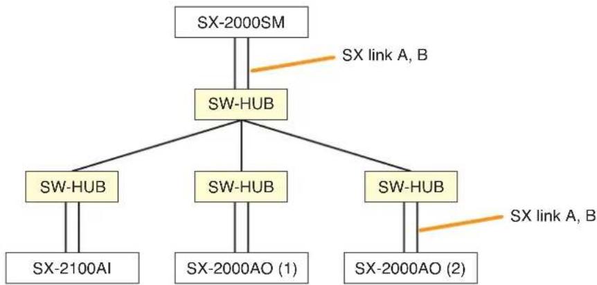
flowchart
graph TD
    A["SX-2000SM"] --> B["SW-HUB"]
    B --> C["SW-HUB"]
    B --> D["SW-HUB"]
    B --> E["SW-HUB"]
    C --> F["SX-2100AI"]
    D --> G["SX-2000AO (1)"]
    E --> H["SX-2000AO (2)"]
    I["SX link A, B"] --> B
    J["SX link A, B"] --> E
4.5.1. Redundant configuration of switching hubs
In the connection example below, the SX Link A and B terminals of each unit are individually connected to different switching hubs. By using switching hubs with failure status output function, if any one of switching hubs fails or the main line breaks, such a failure can be detected.
Notes
- Up to 7-level cascade is allowed for switching hub connections.
• After connection completion, reactivate the SX-2000SM, SX-2000AI, SX-2100AI, SX-2000AO, or SX-2100AO by pressing the Reset key on its front panel. - Perform spanning tree setting within switching hubs. For the setting, contact your network administrator.
- The "External failure input" function needs be assigned to the unit's control input terminal to which the switching hub's failure status output is connected. (For details, refer to the separate Setting Software Instructions, "Event Settings.")

flowchart
graph TD
    A["Switching hub (B-1) Switching hub (A-1)"] --> B["Main line"]
    B --> C["To other switching hub"]
    C --> D["Main line Main line"]
    D --> E["Switching hub (B-2) Switching hub (A-2)"]
    E --> F["Main line"]
    F --> G["Main line"]

    H["STP Category 5 straight cable (with RJ45 connectors)"] --> I["SX-2000SM"]
    I --> J["Main line"]
    J --> K["To other switching hub"]

    L["SX-2100AI"] --> M["SX-2000AI"]
    M --> N["Main line"]
    N --> O["Main line Main line"]

    P["SX-2100AO"] --> Q["SX-2000AO"]
    Q --> R["Main line"]
    R --> S["Main line Main line"]

    T["SX-2000B"] --> U["SX-2000B"]
    U --> V["Main line Main line"]

    W["SX LINK"] --> X["SX LINK"]
    X --> Y["Main line Main line"]

    Z["Control Input"] --> AA["SX LINK"]
    AA --> AB["Main line Main line"]

    AC["SX LINK"] --> AD["SX LINK"]
    AD --> AE["Main line Main line"]
Note: Contact your TOA dealer for more information on switching hubs.
4.5.2. Non-redundant configuration of switching hubs
In the connection example below, both SX Link A and B terminals of each unit are connected to the same switching hub.
Notes
- Up to 7-level cascade is allowed for switching hub connections.
• After connection completion, reactivate the SX-2000SM, SX-2000AI, SX-2100AI, SX-2000AO, or SX-2100AO by pressing the Reset key on its front panel.
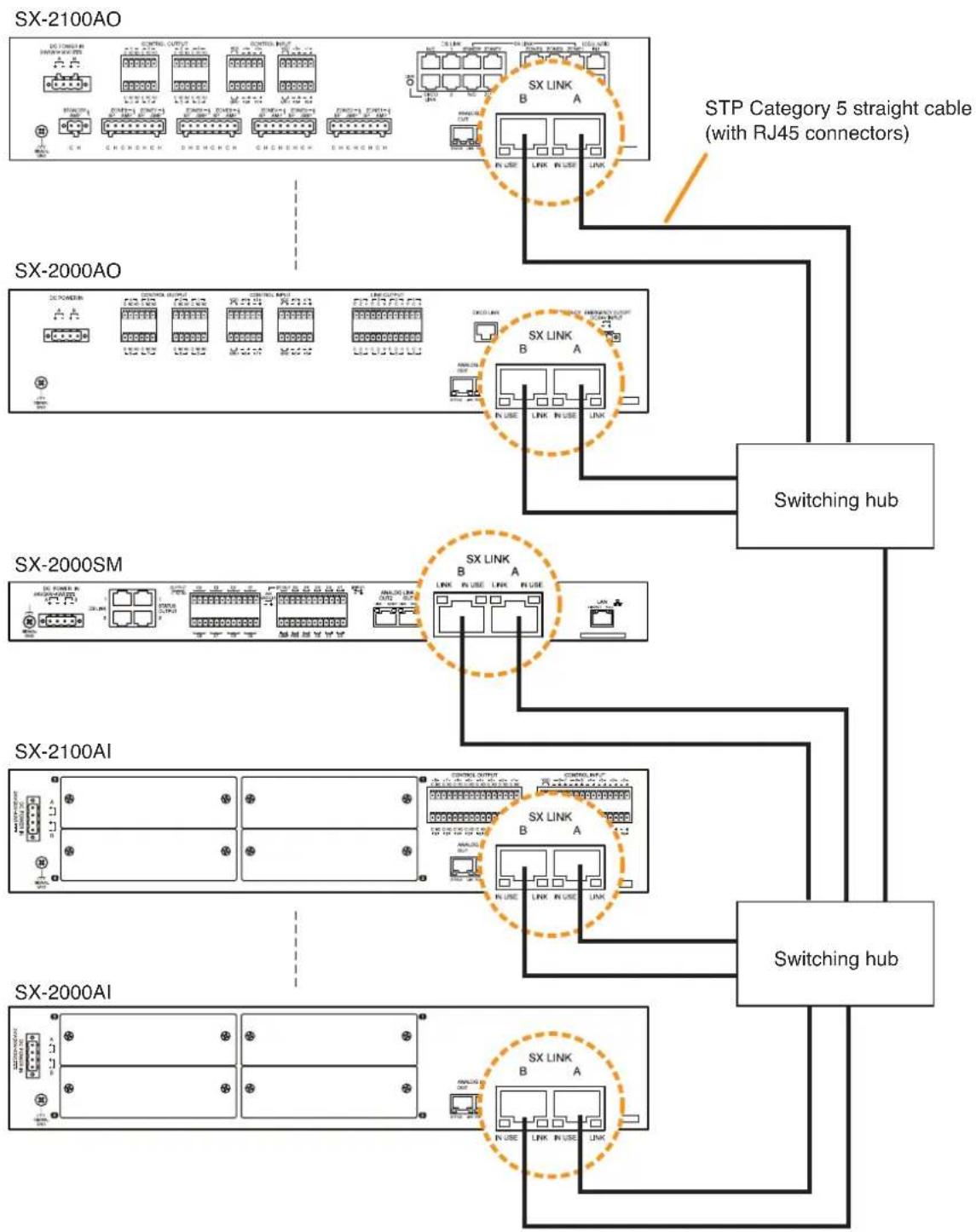
flowchart
graph TD
    A["SX-2100AO"] --> B["STP Category 5 straight cable (with RJ45 connectors)"]
    A --> C["SX-2000AO"]
    C --> D["Switching hub"]
    C --> E["SX-2000SM"]
    E --> F["SX-2100AI"]
    F --> G["Switching hub"]
    F --> H["SX-2000AI"]
    style A fill:#f9f,stroke:#333
    style C fill:#f9f,stroke:#333
    style E fill:#f9f,stroke:#333
    style F fill:#f9f,stroke:#333
    style H fill:#f9f,stroke:#333
Note: Contact your TOA dealer for more information on switching hubs.
4.6. CI/CO Link Terminal Connections
One each of SX-2000CI and SX-2000CO can be cascade-connected to the SX-2000AO or SX-2100AO.
4.6.1. Connecting a single SX-2000CI or SX-2000CO
Set the CI/CO link through switch of the SX-2000CI or SX-2000CO to OFF, then make connection as shown below.

text_image
SX-2000AO or SX-2100AO CI/CO LINK STP Category 5 straight cable fitted with RJ-45 connectors SX-2000CI or SX-2000CO CI/CO LINK THROUGH DATA ON/OFFSet the CI/CO link through switch to OFF. (Factory preset: OFF)
Note
The figure shows the connection between the SX-2000AO and SX-2000CI.
4.6.2. Connecting one each of SX-2000CI and SX-2000CO
Connect the SX-2000CI and SX-2000CO to the SX-2000AO or SX-2100AO in cascade as shown below. The connection order of the SX-2000CI and SX-2000CO can be changed.
Set the CI/CO link through switch of the device directly connected to the SX-2000AO or SX-2100AO to ON, and that of the second cascade-connected device to OFF.
Notes
- Total cable length connecting CI/CO link terminals within the system must be kept shorter than 800 m.
• The figure shows an example when the SX-2000CI is directly connected to the SX-2100AO.
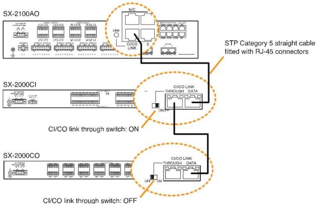
flowchart
graph TD
    A["SX-2100AO"] -->|N/C Link| B["STP Category 5 straight cable fitted with RJ-45 connectors"]
    A -->|CI/CO LINK| C["SX-2000CI"]
    C -->|CI/CO LINK THROUGH DATA ON/OFF| D["SX-2000CO"]
    D -->|CI/CO LINK THROUGH DATA OFF| E["SX-2000CI"]
    style A fill:#f9f,stroke:#333
    style C fill:#ccf,stroke:#333
    style D fill:#cfc,stroke:#333
4.7. Analog Link Terminal Connections
Connecting all SX-2000SM, SX-2000AI, SX-2100AI, SX-2000AO, and SX-2100AO units within the system via Analog link terminals permits general urgency all-calls to be initiated from the RM-200SA Remote Microphone or the RM-200SF Fireman's Microphone through the connected lines if normal broadcasts cannot be made due to equipment failures. (See p. 68, "CPU OFF function settings.")
The entire system can also be reset using these connected lines. (See p. 7 "15. Reset Key", p. 49 "System reset enable/disable settings.")
Make connections from the SX-2000SM's Analog link output terminal to the Analog link input terminal of the SX-2000AI, SX-2100AI, SX-2000AO, and SX-2100AO, and from the Analog link output terminal of the SX-2000AI, SX-2100AI, SX-2000AO, and SX-2100AO to the Analog link input terminal of the SX-2000AI, SX-2100AI, SX-2000AO, and SX-2100AO. Both of the SX-2000SM's Analog output terminals 1 and 2 provide the same operation.
Note
Total cable length connecting analog link terminals within the system must be kept shorter than 800 m.
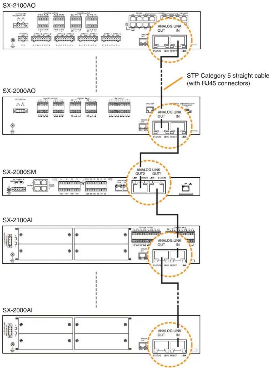
flowchart
graph TD
    A["SX-2100AO"] --> B["STP Category 5 straight cable (with RJ45 connectors)"]
    B --> C["SX-2000AO"]
    C --> D["SX-2000SM"]
    D --> E["SX-2100AI"]
    E --> F["SX-2000AI"]

    subgraph Switch_ configurations
        G["Switch 1: Power, Current, Output, Power Input"] --> H["Analog Link OUT IN"]
        I["Switch 2: Power, Current, Output, Power Input"] --> J["Analog Link OUT IN"]
        K["Switch 3: Power, Current, Output, Power Input"] --> L["Analog Link OUT IN"]
        M["Switch 4: Power, Current, Output, Power Input"] --> N["Analog Link OUT IN"]
        O["Switch 5: Power, Current, Output, Power Input"] --> P["Analog Link OUT IN"]
    end

    style A fill:#f9f,stroke:#333
    style C fill:#f9f,stroke:#333
    style D fill:#f9f,stroke:#333
    style E fill:#f9f,stroke:#333
    style F fill:#f9f,stroke:#333
    style G fill:#ccf,stroke:#333
    style H fill:#ccf,stroke:#333
    style I fill:#ccf,stroke:#333
    style J fill:#ccf,stroke:#333
    style K fill:#ccf,stroke:#333
    style L fill:#ccf,stroke:#333
    style M fill:#ccf,stroke:#333
    style N fill:#ccf,stroke:#333
    style O fill:#ccf,stroke:#333
    style P fill:#ccf,stroke:#333
    style Q fill:#ccf,stroke:#333
    style R fill:#ccf,stroke:#333
    style S fill:#ccf,stroke:#333
    style T fill:#ccf,stroke:#333
    style U fill:#ccf,stroke:#333
    style V fill:#ccf,stroke:#333
    style W fill:#ccf,stroke:#333
    style X fill:#ccf,stroke:#333
4.8. Connections to Use the Surveillance Function
4.8.1. Speaker line surveillance (SX-2100AO only)
The speaker line surveillance function detects 3 types of failures: poor insulation (ground fault), overload (line short), and cable disconnection.
For detecting both overload and cable disconnection, use the method that detects such failures by monitoring the impedance in a speaker line (referred to as Impedance method).
Particularly to improve the accuracy of detecting cable disconnection, use the method that detects cable disconnection by connecting an End-of-line (EOL) unit at the end of speaker line (referred to as EOL method). Features of each method are shown below.
(1) Impedance method
- Applies to various types of speaker cables (no need to use shielded type cables).
- Needs no additional detector to be connected to the speaker line.
- Provides less precision in detection of speaker cable disconnection than the EOL method.
(2) EOL method
- Detects speaker cable disconnection precisely.
- Needs shielded speaker cables to be used.
- Needs an EOL unit to be connected to the speaker line.
[General description of the Impedance method]
The speaker impedance is stored in the SX-2100AO after measured with a pilot tone signal of low frequency. The SX-2100AO continuously observes the speaker line impedance, and compares it with the stored value to judge overload or disconnection of the speaker line.
The speaker line impedance may fluctuate even in normal state with the influence of impedance variations caused by the speaker's impedance change, broadcast signal frequency difference, and ambient temperature change. In such cases, the detection sensitivity can be adjusted. (See p. 130, "Speaker Line Initial Setting.")
In an application that many low power speakers are connected to an amplifier with high power output, the impedance variation stays within the measurement tolerance even if one speaker is disconnected, disabling the detection of speaker cable disconnection. In such cases, adjust the detection sensitivity of cable disconnection or select the EOL method.
![TOA D-921F - [General description of the Impedance method] - 1](/content/2026/06/1214100/images/e81fdea61d871b66b4b87deae8d5daa942ea21b715c633b4f7be349a4a14e854.jpg)
flowchart
graph TD
    A["40 Hz Pilot Tone"] --> B["PA LINK"]
    B --> C["AMP"]
    C --> D["Ground fault detection"]
    C --> E["Short/open circuit detection through impedance detection"]
    D --> F["SP"]
    E --> F
    F --> G["Speaker"]
    G --> H["Speaker"]
    H --> I["Speaker"]
[General description of the EOL method]
Shielded types of cables are used for all speaker lines, and all the shield wires are grounded.
An End-of-line (EOL) unit is connected at the furthest end of speaker line.
This EOL unit produces an impedance of specified value between the speaker line and the shield wire by using a pilot tone signal output from the SX-2100AO.
Observing this impedance, the SX-2100AO judges the speaker line to be disconnected when it cannot detect the specified value. For overload, refer to "General description of the Impedance method" described on the previous page since the SX-2100AO judges overload using the same way as the Impedance method.
Notes
• Ground all of the speaker shield wires and the SX-2100AO's chassis.
- Connect only a single EOL unit per speaker line from an amplifier output. (Do not connect 2 or more EOL units per line.)
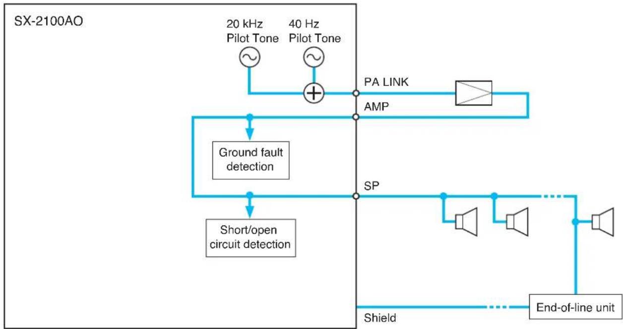
flowchart
graph TD
    A["20 kHz Pilot Tone"] --> B["Ground fault detection"]
    C["40 Hz Pilot Tone"] --> D["Ground fault detection"]
    B --> E["Short/open circuit detection"]
    D --> E
    E --> F["PA LINK"]
    F --> G["AMP"]
    G --> H["End-of-line unit"]
    H --> I["Shield"]
    I --> J["SP"]
    J --> K["Ground fault detection"]
IMPORTANT
In both Impedance method and EOL method described below, be sure to make the speaker line initial setting (p. 130) after connection completion when the speaker line surveillance is to be performed.
[Impedance method]
The cable connection in this method is the same as when the surveillance function is not used. (See p. 107.) To use the surveillance function, make the necessary setting on the SX-2000 Setting Software.
Note
For the setting procedures, refer to the separate Setting Software Instructions.
[EOL method]

flowchart
graph TD
    A["End-of-line unit"] --> B["Speaker"]
    B --> C["8P removable terminal plug (supplied with the SX-2100AO)"]
    C --> D["Amplifier input terminal"]
    D --> E["Shield"]
    E --> F["PA OUT (SP LINK)"]
    F --> G["Amplifier output terminal"]
    G --> H["VP-2122"]
    H --> I["Amplifier Input Module VP-200VX"]
    I --> J["Audio signal output"]
    J --> K["Applicable cable: AWG16 - 24"]
    K --> L["PA LINK VP-200VX"]
    L --> M["Amplifier Input Module VP-200VX"]
    M --> N["Audio signal output"]
    N --> O["Applicable cable: CAT5-STP"]
    O --> P["PA LINK VP-200VX"]
    P --> Q["Audio signal output"]
    Q --> R["End-of-line unit"]
IMPORTANT
In both Impedance method and EOL method described below, be sure to make the speaker line initial setting (p. 130) after connection completion when the speaker line surveillance is to be performed.
[Impedance method]
The cable connection in this method is the same as when the surveillance function is not used. (See p. 108.) To use the surveillance function, make the necessary setting on the SX-2000 Setting Software.
Notes
- The attenuator shown in the diagram below is assumed to be bypassed when DC voltage is applied to the attenuator control line.
- The zone numbers coincide with the control output numbers.
- Set the application of the control output that connects an attenuator to "ATTENUATOR" on the SX-2000 Setting Software. For the setting procedures, refer to the separate Setting Software Instructions.
- When an emergency broadcast is made, the attenuators are bypassed. To use emergency broadcast and speaker line surveillance function, make necessary settings on the SX-2000 Setting Software. (See the separate Setting Software Instructions, "Basic settings.")
[EOL method]

flowchart
graph TD
    A["Control output terminals"] --> B["DC POWER Supply (+) (-)"]
    A --> C["(-) (+) N SP Relay Control"]
    A --> D["SX-2100AO"]
    A --> E["6P removable terminal plug (supplied with the SX-2100AO)"]
    A --> F["8P removable terminal plug (supplied with the SX-2100AO)"]
    G["End-of-line unit"] --> H["Relay Control"]
    I["Control output relay contact capacity Withstand voltage: 40 V DC Contact current: 0.3 A"] --> A
    J["Speaker connection terminals and amplifier input terminals"] --> A
    K["6P removable terminal plug (supplied with the SX-2100AO)"] --> A
    L["6P removable terminal plug (supplied with the SX-2100AO)"] --> A
    M["6P removable terminal plug (supplied with the SX-2100AO)"] --> A
    N["6P removable terminal plug (supplied with the SX-2100AO)"] --> A
    O["6P removable terminal plug (supplied with the SX-2100AO)"] --> A
    P["6P removable terminal plug (supplied with the SX-2100AO)"] --> A
    Q["6P removable terminal plug (supplied with the SX-2100AO)"] --> A
    R["6P removable terminal plug (supplied with the SX-2100AO)"] --> A
    S["6P removable terminal plug (supplied with the SX-2100AO)"] --> A
    T["6P removable terminal plug (supplied with the SX-2100AO)"] --> A
    U["6P removable terminal plug (supplied with the SX-2100AO)"] --> A
    V["6P removable terminal plug (supplied with the SX-2100AO)"] --> A
    W["6P removable terminal plug (supplied with the SX-2100AO)"] --> A
    X["6P removable terminal plug (supplied with the SX-2100AO)"] --> A
    Y["6P removable terminal plug (supplied with the SX-2100AO)"] --> A
    Z["6P removable terminal plug (supplied with the SX-2100AO)"] --> A
    AA["6P removable terminal plug (supplied with the SX-2100AO)"] --> A
    AB["6P removable terminal plug (supplied with the SX-2100AO)"] --> A
    AC["6P removable terminal plug (supplied with the SX-2100AO)"] --> A
    AD["6P removable terminal plug (supplied with the SX-2100AO)"] --> A
    AE["6P removable terminal plug (supplied with the SX-2100AO)"] --> A
    AF["6P removable terminal plug (supplied with the SX-2100AO)"] --> A
    AG["6P removable terminal plug (supplied with the SX-2100AO)"] --> A
    AH["6P removable terminal plug (supplied with the SX-2100AO)"] --> A
    AI["6P removable terminal plug (supplied with the SX-2100AO)"] --> A
    AJ["6P removable terminal plug (supplied with the SX-2100AO)"] --> A
    AK["6P removable terminal plug (supplied with the SX-2100AO)"] --> A
    AL["6P removable terminal plug (supplied with the SX-2100AO)"] --> A
    AM["6P removable terminal plug (supplied with the SX-2100AO)"] --> A
    AN["6P removable terminal plug (supplied with the SX-2100AO)"] --> A
    AO["6P removable terminal plug (supplied with the SX-2100AO)"] --> A
    AP["6P removable terminal plug (supplied with the SX-2100AO)"] --> A
    AQ["6P removable terminal plug (supplied with the SX-2100AO)"] --> A
    AR["6P removable terminal plug (supplied with the SX-2100AO)"] --> A
    AS["6P removable terminal plug (supplied with the SX-2100AO)"] --> A
    AT["6P removable terminal plug (supplied with the SX-2100AO)"] --> A
    AU["6P removable terminal plug (supplied with the SX-2100AO)"] --> A
    AV["6P removable terminal plug (supplied with the SX-2100AO)"] --> A
    AW["6P removable terminal plug (supplied with the SX-2100AO)"] --> A
    AX["6P removable terminal plug (supplied with the SX-2100AO)"] --> A
    AY["6P removable terminal plug (supplied with the SX-2100AO)"] --> A
Note
The speaker line with attenuators installed cannot be detected for its open-circuit state with the Speaker Line Surveillance function.
4.8.2. Control line surveillance
Function for detecting a wiring fault in the cable connected to the external control output device can be set to the control input terminals of the SX-2000SM and SX-2000CI.
Connect the resistors to the cable of which fault is to be detected as shown below.
For the method of setting the fault detection function to the control input terminals, refer to the separate Setting Software Instructions.
Notes
- Be sure to connect the resistors as shown in the diagram below.
If no resistors are connected or resistors other than specified are used, the fault detection function will not work correctly. - To assure stable operation of this wiring fault detection, it is recommended to use a shielded twisted pair cable of 10m or less.
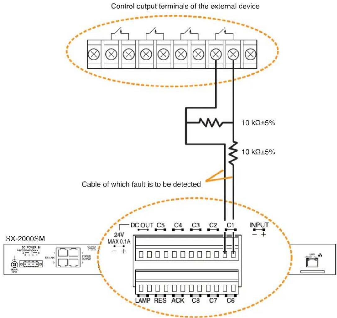
text_image
Control output terminals of the external device 10 kΩ±5% 10 kΩ±5% Cable of which fault is to be detected SX-2000SM DC POWER IN SWITCHER/VEGETS DC LINK STATUS OUTPUT 24V MAX 0.1A LAMP RES ACK C8 C7 C6 INPUT - +Control input terminals
Notes
• The figure shows a connection example for the SX-2000SM. This connection also applies to the SX-2000CI.
- Be sure to connect each shield wire to the functional ground terminal of each device.
5. SPEAKER LINE INITIAL SETTING
To perform Speaker Line Surveillance, be sure to make the initial settings for the SX-2100AO as follows after connection completion of the SX-2000 system.
5.1. Setting Items
[Initial impedance value setting]
The SX-2100AO determines whether the speaker line is open or shorted using this initial value as reference value (normal impedance value).
Important
When using the surveillance function, be sure to set the initial impedance value.
[Speaker line OPEN sensitivity adjustment]
The sensitivity can be adjusted so that the SX-2100AO can judge the speaker line open on the basis of the initial value.
[Speaker line SHORT sensitivity adjustment]
The sensitivity can be adjusted so that the SX-2100AO can judge the speaker line shorted on the basis of the initial value.
5.2. OPEN/SHORT Criterion by Comparing the Current Value with the Initial Value
The set sensitivity values and the current value are expressed as rations to the initial value (defined as 100 %). If OPEN and SHORT sensitivities remain factory-preset, the speaker line is judged shorted when the current value is less than half the initial value, and open when it is more than twice the initial value.

bar_stacked
(Sensitivity adjustable range) (Current value) | Category | Current Value (%) | Impedance Ratio | | :--- | :--- | :--- | | Short | 5 | 1 | | Normal | 100 | Initial Value (Reference value) | | Opening | 800 | 9999 | (5 - 50 variable, Default: 50) | (101 - 800 variable, Default: 200)[Sensitivity setting example]
When the SHORT sensitivity is set to 25 %, and OPEN sensitivity to 150 %.

bar_stacked
| Category | Segment 1 (%) | Segment 2 (%) | Segment 3 (%) | Segment 4 (%) | |---|---|---|---|---| | Judgment | 1 | - | - | - | | SHORT | - | - | - | - | | NORMAL | - | - | - | - | | OPEN | - | - | - | - | | Total | 5 | 25 | 100 | 150 | | Below 800% | 800 | - | - | - | | Above 9999% | - | - | - | - |5.3. Setting Procedures
5.3.1. Summary setting procedures
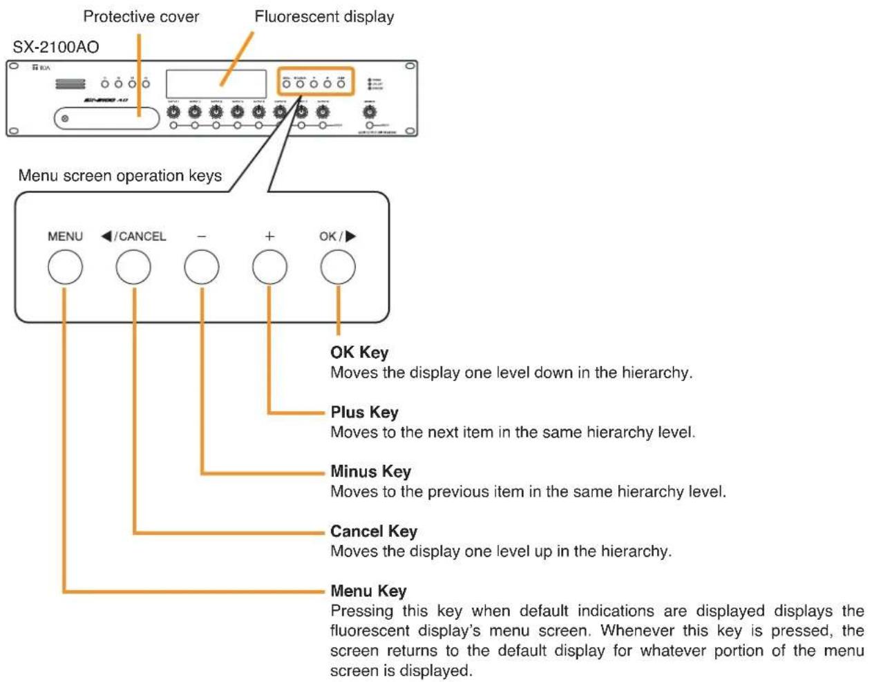
text_image
Protective cover Fluorescent display SX-2100AO Menu screen operation keys MENU ←/CANCEL - + OK / OK Key Moves the display one level down in the hierarchy. Plus Key Moves to the next item in the same hierarchy level. Minus Key Moves to the previous item in the same hierarchy level. Cancel Key Moves the display one level up in the hierarchy. Menu Key Pressing this key when default indications are displayed displays the fluorescent display's menu screen. Whenever this key is pressed, the screen returns to the default display for whatever portion of the menu screen is displayed.Use the SX-2100AO's fluorescent display and front panel-mounted keys to perform settings. Setting the DIP switch 8 inside the protective cover on the SX-2100AO's front panel to ON enables the impedance initialization setting menu to be displayed on the fluorescent display. Follow the procedures below to perform settings for all the SX-2100AOs within the system.
Step 1. Remove the protective cover on the SX-2100AO's front panel by unscrewing it with a Phillips screwdriver.

flowchart
graph LR
    A["Protective cover"] --> B["Screw"]
    B --> C["Inside of the protective cover"]
    C --> D["USB"]
    C --> E["RUN"]
    C --> F["ID NUMBER"]
    C --> G["RESET"]
    C --> H["SETTING"]
    H --> I["ON"]
    C --> J["ID switches Reset key"]
Note: Switch 8 is set to OFF by default.
Step 2. Set the DIP switch 8 to ON.
The impedance initialization setting menu can be displayed on the fluorescent display.
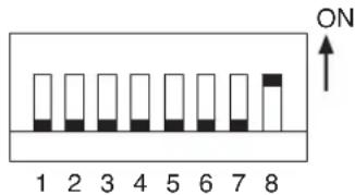
text_image
ON 1 2 3 4 5 6 7 8Step 3. Press the Menu key to enter the menu screen.
Step 4. Press the Plus (+) key 3 times until the "4-IMPEDANCE STATUS" (Impedance initialization setting menu) is displayed.
Note
The impedance initialization setting flow is shown on p. 134.

flowchart
graph TD
    A["Default Display\nAO- 16 VER 300 . . ."] --> B["MENU 3"]
    B --> C["1 - INFORMATION"]
    C --> D["+"]
    D --> E["4"]
    E --> F["+"]
    F --> G["Initialization Menu\n4 - IMPEDANCE STATUS"]
    G --> H["OK/▶"]
    H --> I["Initial impedance value setting\nSET INITIAL IMP >"]
    I --> J["+"]
    J --> K["Speaker line OPEN sensitivity adjustment\nADJUST OPEN RANGE>"]
    K --> L["+"]
    L --> M["Speaker line SHORT sensitivity adjustment\nADJUST SHORT RANGE"]
    M --> N["MENU 8"]
    N --> O["Default Display\nAO- 16 VER 300 . . ."]
Step 5. Set an initial impedance value.
Pressing the OK key while the impedance initialization setting menu screen is displayed changes the display to "SET INITIAL IMP" (Initial impedance value setting) screen. For detailed description of its setting procedure, refer to p. 135.
Step 6. Adjust the OPEN sensitivity value as needed.
Pressing the Plus (+) key while the "SET INITIAL IMP" screen is displayed changes the display to "ADJUST OPEN RANGE" (Speaker line OPEN sensitivity adjustment) screen. For detailed description of its setting procedure, refer to p. 137.
Step 7. Adjust the SHORT sensitivity value as needed.
Pressing the Plus (+) key while the "ADJUST OPEN RANGE" screen is displayed changes the display to "ADJUST SHORT RANGE" (Speaker line SHORT sensitivity adjustment) screen. For detailed description of its setting procedure, refer to p. 138.
Step 8. When the setting is complete, press the MENU key.
The screen reverts to the default display.
Note
Whenever the Menu key is pressed, the screen returns to the default display for whatever portion of the menu screen is displayed.
Step 9. Set the DIP switch 8 to OFF.
Step 10. Replace the protective cover.
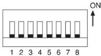
text_image
ON 1 2 3 4 5 6 7 85.3.2. Screen display (Common)
Shown below is the fluorescent display while in the impedance initialization setting mode.
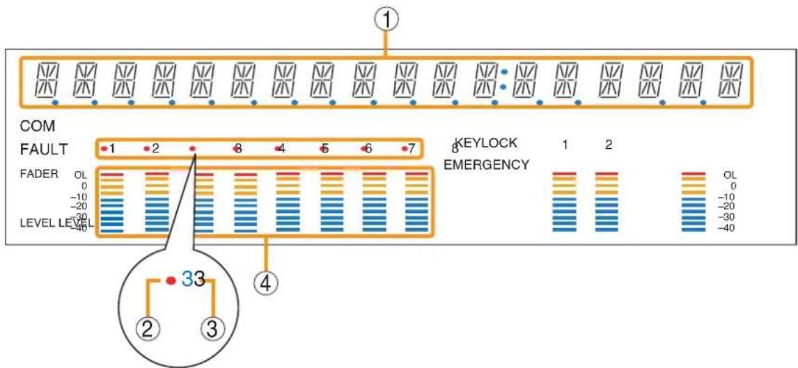
text_image
COM FAULT FADER OL 0 -10 -20 -30 -40 LEVEL LEVEL 1 2 8 4 5 6 7 KEYLOCK EMERGENCY 1 2 OL 0 -10 -20 -30 -40 33 ② ③ ④1. Text Display Area
Displays the menu screen and information.
2. Channel Selection Indicator
Lights when the corresponding output channel is selected.
3. Channel Number Indicator
Indicates the channel number.
All channel numbers (1 - 8) remain lit while in this setting mode.
4. Level Meter
Light-up position of LED indicates the initial impedance value (reference value) and degree of OPEN or SHORT of the selected channel, at which the indicator (2) is illuminated.
All the LEDs go off if the "CLEAR INITIAL IMP." (Setting clear) is selected.

flowchart
graph TD
    A["Default Display AO-16 VER. 3.00"] --> B["MENU"]
    B --> C["1 - INFORMATION"]
    C --> D["Initialization Menu"]
    D --> E["4 - IMPEDANCE STAT US SET INITIAL IMP"]
    E --> F["Speaker line OPEN sensitivity adjustment ADJUST OPEN RANGE"]
    F --> G["Speaker line SHORT sensitivity adjustment ADJUST SHORT RANGE"]
    G --> H["Setting clear CLEAR INITIAL IMP"]
    H --> I["OK/▶ OK/▶"]
    I --> J["INITIALIZE ALL CH"]
    J --> K["CH 1 1 0 0 NORMAL"]
    K --> L["..."]
    L --> M["CH 8 1 0 0 NORMAL"]
    M --> N["OK/▶ CHANGE VALUE: 200"]
    N --> O["OK/▶ CHANGE VALUE: 50"]
    O --> P["OK/▶ CHANGE VALUE: 50"]
    P --> Q["OK/▶ CHANGE VALUE: 50"]
    Q --> R["OK/▶ CHANGE VALUE: 50"]
    R --> S["OK/▶ CHANGE VALUE: 50"]
    S --> T["OK/▶ CHANGE VALUE: 50"]
    T --> U["OK/▶ CHANGE VALUE: 50"]
    U --> V["OK/▶ CHANGE VALUE: 50"]
5.3.4. Setting an initial impedance value
Notes
- When attenuators are connected to the speaker line, set their attenuation level to their maximum position. Otherwise, the initial impedance value cannot be set correctly.
- Be sure to perform this setting after completion of connection work.
- Be sure to reset the initial impedance value if any wiring or connection has been changed after completion of the setting.
Step 1. Press the OK key while the "SET INITIAL IMP" (Initial impedance value setting) screen is displayed. The channel selection screen is displayed.
Step 2. Select the channel to be initialized. Press the Plus (+) or Minus (−) key to select all channels or desired channel (from CH1 through CH8).
Step 3. Press the OK key. The initial value is automatically set, and the screen reverts to the screen of the channel selected in Step 2.
Note
If the initial value cannot be set, the level meter of the corresponding channel does not light. This cause possibly lies in speaker line failure (open or short) or inappropriate load. The level meter also does not light when the connection is not made.
[When the all-channel screen appears on the fluorescent display after the initial value has been set]
- The 5th indicators (segments) from the bottom of the level meters corresponding only to the speaker-connected channels light up after completion of the initial value setting. These values are the reference values.
- The level indicator goes up and down in response to the current value. The meter shows a short state of speaker line in the range above the reference value, and an open state in the range below it.
![TOA D-921F - [When the all-channel screen appears on the fluorescent display after the initial value has been set] - 1](/content/2026/06/1214100/images/225d55bfdb40375cb7e206e6b45b25a34d0261d30b4b9a58388e647a6eb093d8.jpg)
flowchart
graph TD
    A["SET INITIAL IMP"] -->|OK/1| B["Channel selection"]
    B --> C["INITIALIZE ALL CH"]
    C --> D["CH 1 1 0 0 NORMAL"]
    D --> E["CH 8 1 0 0 NORMAL"]
    E --> F["Initial impedance value being set INITIALIZING ---"]
    F --> G["Finish FINISHED"]
    G --> H["A"]
    style A fill:#f9f,stroke:#333
    style B fill:#ccf,stroke:#333
    style C fill:#cfc,stroke:#333
    style D fill:#fcc,stroke:#333
    style E fill:#cff,stroke:#333
    style F fill:#ffc,stroke:#333
    style G fill:#cfc,stroke:#333
    style H fill:#fcc,stroke:#333
![TOA D-921F - [When the all-channel screen appears on the fluorescent display after the initial value has been set] - 2](/content/2026/06/1214100/images/580624ad5d2eb28f16897b267851d7e6cab90f025dfbfc292b6839b16397c83e.jpg)
bar
INITIALIZE ALL CH | COM | FAULT | KEYLOCK | EMERGENCY | LEVEL | |---|---|---|---|---| | 1 | 1 | 8 | 1 | OL | | 2 | 2 | 8 | 2 | 0 | | 3 | 3 | 8 | 2 | -10 | | 4 | 4 | 8 | 2 | -20 | | 5 | 5 | 8 | 2 | -20 | | 6 | 6 | 8 | 2 | -30 | | 7 | 7 | 8 | 2 | -40 | LEVEL: -40, -30, -20, -10, 0, 1, 2, 1, 2, 1 respectively.The 5th indicators (segments) from the bottom
[When each individual channel is displayed on the fluorescent display after the initial value has been set]
- The 5th indicator (segment) from the bottom of the selected channel's level meter lights up after completion of the initial value setting. This value is the reference value.
- The level indicator goes up and down in response to the current value. The meter shows a short state of speaker line in the range above the reference value, and an open state in the range below it.
- Current impedance status of the selected channel can be checked in the text display area.
Current value: Displays the ratio of current impedance to the initial one in real-time.
This indicator remains unlit when the speaker line is not connected. The display range is 0 to 9999 and over. A blank is displayed if no initial setting is or could have been performed.
Judgment: Displays the judgment results below.
| Judgment | Contents |
| SHORT | Line shorted |
| NORMAL | Line normal |
| OPEN | Line open |
| EARTH | Ground fault |
| --- | Initial value is not set. |
![TOA D-921F - [When each individual channel is displayed on the fluorescent display after the initial value has been set] - 1](/content/2026/06/1214100/images/9bfe856f8846dffac2417e8aa99250f4eedd3e5f173f26b10c1ec7ebbb0b40e1.jpg)
other
| Fault | Current Value | |-------|---------------| | FADER | OL | | -10 | -10 | | -20 | -20 | | LEVEL LEVEL | -40 | | KEYLOCK EMERGENCY | 1 | | Judgment | NORMAL |The 5th indicator (segment) from the bottom
Note: The figure shows an example when CH3 is selected.
5.3.5. Adjusting the speaker line's OPEN sensitivity
Open sensitivity is expressed as the ratio to the initial value (defined as 100 %) and can be adjusted in the range of 101 % to 800 %. It is set to "200" (the 4th indicators from the top light) for all the channels by default.
Note
Moving the setting closer to 101 % increases the OPEN sensitivity, and thus improves the accuracy of "OPEN" detection. Moving the setting closer to 800 % decreases the OPEN sensitivity, and thereby stabilizes the operation of the "OPEN" detection.
Step 1. Press the OK key while the "ADJUST OPEN RANGE" (Speaker line OPEN sensitivity adjustment) screen is displayed.
The "SELECT CHANNEL" (channel selection) screen is displayed.
OPEN sensitivity set positions for the all channels can be confirmed from the light-up positions of the LEDs. (Lighting range of the LEDs corresponds to the variable range of 101 to 800 of the OPEN sensitivity.)
(Level meter on the fluorescent display)
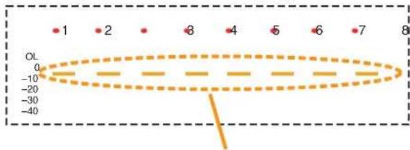
scatter
| Point | Value | |---|---| | 1 | -10 | | 2 | -10 | | 3 | -10 | | 4 | -10 | | 5 | -10 | | 6 | -10 | | 7 | -10 | | 8 | -10 |Light-up position at 200 by default (as a rough guide)
Step 2. Select the channel for which the setting is to be changed.
Press the Plus (+) or Minus (−) key to select all channels or desired channel (from CH1 through CH8).
Selected channel(s) can be confirmed by the Channel selection indicator(s) on the fluorescent display.
(Channel Selection Indicators on the fluorescent display)
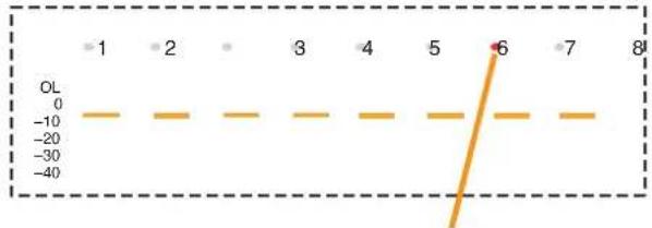
line
| Point | Value | |---|---| | 1 | -10 | | 2 | -10 | | 3 | -10 | | 4 | -10 | | 5 | -10 | | 6 | -10 | | 7 | -10 | | 8 | -10 |Indicator corresponding to the selected channel lights red.
Speaker line OPEN sensitivity adjustment

flowchart
graph TD
    A["ADJUST OP EN RANGE"] --> B{OK/}
    B --> C["1"]
    C --> D["Channel selection"]
    D --> E["SELECT CHANNEL + / -"]
    E --> F{+ or -}
    F --> G["2"]
    G --> H["SELECT CHANNEL + / -"]
    H --> I{OK/}
    I --> J["3"]
    J --> K["Setting value change"]
    K --> L["CHANGE VA LUE: 200"]
    L --> M{+ or -}
    M --> N["4"]
    N --> O["(Example)"]
    O --> P["CHANGE VA LUE: 250"]
    P --> Q{A}
    Q --> R["Save in progress"]
    R --> S["NOW SAVING"]
    S --> T["Finish"]
    T --> U["FINISHED"]
    U --> V["displayed."]
Step 3. Press the OK key.
The OPEN sensitivity setting screen for the selected channel is displayed.
The set value of the selected channel is displayed in the text display area.
Step 4. Set the value using the Plus (+) or Minus (−) key.
The setting range is 101 to 800.
Values can be adjusted in 1 steps ranging from 101 to 110, in 10 steps ranging from 110 to 200 and in 100 steps thereafter. The light-up position of the LED goes up or down accordingly when the setting value is changed.
Step 5. Press the OK key.
The setting save starts with its process message displayed, and the screen reverts to that in Step 4 when finished.
Be sure to save the settings as doing otherwise may cause them to revert to the original settings at the time of system reset.
5.3.6. Adjusting the speaker line's SHORT sensitivity
SHORT sensitivity is expressed as the ratio to the initial value (defined as 100 %) and can be adjusted in the range of 5 % to 50 %. It is set to "50" (the indicators at the top light) for all the channels by default.
Note
Moving the setting closer to 5% decreases the SHORT sensitivity, and thereby stabilizes the operation of the "SHORT" detection.
Important
Adjust the SHORT sensitivity within the range not exceeding two times the power amplifier's rated load, as doing otherwise may cause damage to the power amplifier.
(Example)
- When the speakers with the rated load are connected: Set to "50."
- When the speakers with 1/2 rated load are connected: Set in the range of "25" to "50."
Step 1. Press the OK key while the "ADJUST SHORT RANGE" (Speaker line SHORT sensitivity adjustment) screen is displayed.
The "SELECT CHANNEL" (channel selection) screen is displayed.
SHORT sensitivity set positions for the all channels can be confirmed from the light-up positions of the LEDs. (Lighting range of the LEDs corresponds to the variable range of 5 to 50 of the SHORT sensitivity.)
(Level meter on the fluorescent display)

scatter
| Point | Value | |-------|-------| | 1 | 0 | | 2 | 0 | | 3 | 0 | | 4 | 0 | | 5 | 0 | | 6 | 0 | | 7 | 0 | | 8 | 0 |The indicators at the top light when set to "50" by default.
Step 2. Select the channel for which the setting is to be changed.
Press the Plus (+) or Minus (−) key to select all channels or desired channel (from CH1 through CH8).
Selected channel(s) can be confirmed by the Channel selection indicator(s) on the fluorescent display.
(Channel Selection Indicators on the fluorescent display)

line
| Point | Value | |---|---| | 1 | -10 | | 2 | -10 | | 3 | -10 | | 4 | -10 | | 5 | -10 | | 6 | -40 | | 7 | -10 | | 8 | -10 |Indicators corresponding to the selected channel light red.
Step 3. Press the OK key.
The SHORT sensitivity setting screen for the selected channel is displayed. The set value of the selected channel is displayed in the text display area.
Speaker line SHORT sensitivity adjustment

text_image
ADJUST SHORT RANGE OK/▶ 1Channel selection
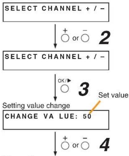
flowchart
graph TD
    A["SELECT CHANNEL + / -"] --> B["+ or -"]
    B --> C["SELECT CHANNEL + / -"]
    C --> D["OK/"]
    D --> E["Setting value change"]
    E --> F["CHANGE VA LUE: 50"]
    F --> G["+ or -"]
    G --> H["4"]
(Example)
CHANGE VA LUE: 25

Save in progress


FINISHED

Step 4. Set the value using the Plus (+) or Minus (−) key.
The setting range is 5 to 50.
Values can be adjusted in 5 steps. The light-up position of the LED goes up or down accordingly when the setting value is changed.
Step 5. Press the OK key.
The setting save starts with its process message displayed, and the screen reverts to that in Step 4 when finished.
Be sure to save the settings as doing otherwise may cause them to revert to the original settings at the time of system reset.
5.3.7. Clearing the settings
The initial impedance value and the set values of OPEN and SHORT sensitivity can be cleared and reset to the factory default.
Step 1. Press the OK key while the "CLEAR INITIAL IMP." (Setting clear) screen is displayed.
The "SELECT CHANNEL" (channel selection) screen is displayed.
Step 2. Select the channel for which the setting is to be cleared.
Press the Plus (+) or Minus (−) key to select all channels or desired channel (from CH1 through CH8).
Selected channel(s) can be confirmed by the Channel selection indicator(s) on the fluorescent display.
(Channel Selection Indicators on the fluorescent display)
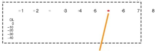
scatter
| Point | Value | |---|---| | 1 | 1 | | 2 | 2 | | 3 | 3 | | 4 | 4 | | 5 | 5 | | 6 | 6 | | 7 | 7 | | 8 | 8 | OL -0 -10 -20 -30 -40Indicator corresponding to the selected channel lights red.
Step 3. Press the OK key.
The setting clear starts with its process message displayed, and the screen reverts to that in Step 2 when finished.
Settings cleared are not saved.

flowchart
graph TD
    A["Setting clear\nCLEAR INITIAL IMP."] --> B{OK/▶ 1}
    B --> C["Channel selection\nSELECT CHANNEL + / -"]
    C --> D{+ or - 2}
    D --> E["SELECT CHANNEL + / -"]
    E --> F{A}
    F --> G["Setting clear in progress\nCLEAR VALUEIMP."]
    G --> H["Finish\nFINISHED"]
    H --> I["A"]
6. INSERTING A CF CARD
6.1. Using Settings Data
The SX-2000 system is operated by storing the data set using the SX-2000 Setting Software on a CF card and inserting the card into the SX-2000SM.
Note
Be sure to insert the CF card containing the settings data into the CF card slot.
6.2. Inserting a CF Card (SX-2000SM: DIP switch 2 operation)
The DIP switch must be set when inserting the CF card into the SX-2000SM.
Follow the procedure below:
Note
Do not operate the DIP switch while the CF card access indicator inside the protective cover is flashing.
Step 1. Remove the protective cover on the SX-2000SM's front panel by removing the screws securing it using a Phillips screwdriver.
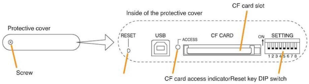
flowchart
graph LR
    A["Protective cover"] --> B["Inside of the protective cover"]
    B --> C["SETTING"]
    C --> D["CF card slot"]
    D --> E["USB"]
    E --> F["ACCESS"]
    F --> G["CF CARD"]
    G --> H["ON"]
    H --> I["1 2 3 4 5 6 7 8"]
    J["Screw"] --> A
    K["CF card access indicatorReset key DIP switch"] --> C
Step 2. Confirm that the CF card access indicator is unlit.
Step 3. Set DIP switch 2 to ON.
Note
DIP switch 2 is set to the OFF position by default.

text_image
ON 1 2 3 4 5 6 7 8Step 4. Insert the CF card containing the settings data into the CF card slot.
Then, the buzzer sounds.
Setting DIP switch 2 to OFF in Step 5 stops the buzzer.
Step 5. Set DIP switch 2 to OFF.
Step 6. Press the Reset key.
The SX-2000 system is reactivated.

text_image
ON 1 2 3 4 5 6 7 8Note
Reactivating the system stops broadcasts currently in progress.
Step 7. Replace the protective cover.
7. TIME SETTINGS
Time, which is recorded in the SX-2000 system's operation log inside the SX-2000SM, must be set.
Note
The SX-2000SM's internal battery will retain the set time for approximately one week. If there is a period of a week or longer between equipment assembly and wiring to on-site installation, it will likely be necessary to perform the time setting again after the system is installed on the site.
Step 1. Connect the SX-2000SM and the PC installed with the SX-2000 software to the switching hub.
Connect the SX-2000SM's LAN connection terminal to a 10BASE-T- or 100BASE-TX-compatible switching hub.
Use STP Category 5 Standard straight LAN cable fitted with RJ45 connectors.
Notes
- The distance between the SX-2000SM and the switching hub must be less than 100 meters.
- Do not connect the switching hub to the LAN.
- Avoid directly connecting the SX-2000SM to the PC via a cross cable.

flowchart
graph TD
    A["SX-2000SM"] --> B["Switching hub"]
    B --> C["PC with the SX-2000 Setting Software installed"]
    B --> D["LAN connection terminal"]
    D --> E["Switching hub"]
    style A fill:#f9f,stroke:#333
    style B fill:#ccf,stroke:#333
    style C fill:#cfc,stroke:#333
    style D fill:#fcc,stroke:#333
    style E fill:#ffc,stroke:#333
Step 2. Perform the time setting from a PC.
For details, see the separate Setting Software Instructions, "Adjusting the Time for the SX-2000SM."
8. KEY LOCK SETTINGS AND CANCELLATION
8.1. SX-2000AI and SX-2100AI (DIP Switch 1 Operation)
It is possible to disable the input volume controls and channel keys in order to prevent mistaken operation. The input volume level set while the key lock function is used takes effect after the key lock has been released.
Note
When the SX-2000 system is placed in an emergency condition during key lock OFF, the emergency sound level preset with the front-mounted volume control knob is invalid, but that defined by the SX-2000 Setting Software is valid.
During key lock ON, however, the volume level set with the input volume control knob is valid even if the SX-2000 system is placed in an emergency condition. Before setting key lock function to ON, be sure to adjust the input volume control knob corresponding to the emergency source channel for a proper sound level.
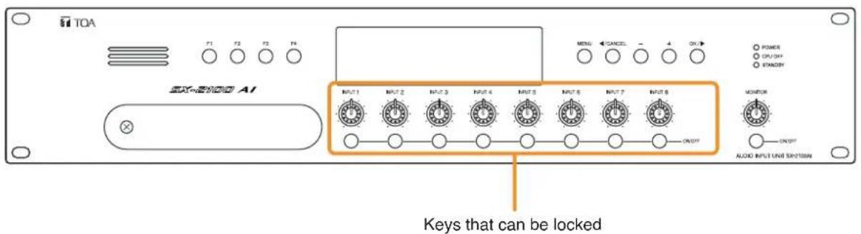
text_image
TOA F1 F2 F3 F4 MENI CANCEL - 4 OK POWER CLOTH STANDARD INT1 INPUT 1 INPUT 2 INPUT 3 INPUT 4 INPUT 5 INPUT 6 INPUT 7 INPUT 8 ONOFF MONITOR ONOFF ALOX INPUT UNIT SWITCH AI OK Keys that can be lockedNote: The figure shows the SX-2100AI.
Step 1. Remove the protective cover on the SX-2000AI's or SX-2100AI's front panel by removing the screws securing it using a Phillips screwdriver.
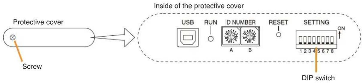
flowchart
graph LR
    A["Protective cover"] --> B["Screw"]
    B --> C["Inside of the Protective Cover"]
    C --> D["USB"]
    C --> E["RUN"]
    C --> F["ID NUMBER"]
    C --> G["RESET"]
    C --> H["SETTING"]
    H --> I["DIP switch"]
    style A fill:#f9f,stroke:#333
    style B fill:#ccf,stroke:#333
    style C fill:#cfc,stroke:#333
    style D fill:#fcc,stroke:#333
    style E fill:#cff,stroke:#333
    style F fill:#ffc,stroke:#333
    style G fill:#cfc,stroke:#333
    style H fill:#fcc,stroke:#333
    style I fill:#cfc,stroke:#333
Step 2. Set the switches.
Note: DIP switch 1 is set to OFF by default.
2-1. If setting a key lock function: Set DIP switch 1 to ON. When keys have been locked, the KEY LOCK indicator in the fluorescent display lights.

text_image
1 2 3 4 5 6 7 8 ON2-2. If canceling a key lock function: Set DIP switch 1 to OFF. When key locking has been cancelled, the KEY LOCK indicator in the fluorescent display goes off.

text_image
1 2 3 4 5 6 7 8 ONStep 3. Replace the protective cover.
8.2. SX-2000AO and SX-2100AO (DIP Switch 1 Operation)
It is possible to disable the output volume controls and channel keys in order to prevent mistaken operation. The output volume level set while the key lock function is used takes effect after the key lock has been released.
Note
When the SX-2000 system is placed in an emergency condition during key lock OFF, the output level for the emergency broadcast zone preset with the front-mounted volume control knob is invalid, but that defined by the SX-2000 Setting Software is valid.
During key lock ON, however, the volume level set with the output volume control knob is valid even if the SX-2000 system is placed in an emergency condition. Before setting key lock function to ON, be sure to adjust the output volume control knob corresponding to the emergency broadcast zone for a proper sound level.
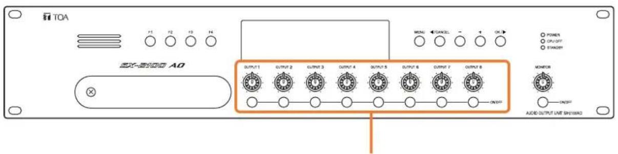
text_image
TOA P1 P2 P3 P4 EX-2100 AO OUTPUT 1 OUTPUT 2 OUTPUT 3 OUTPUT 4 OUTPUT 5 OUTPUT 6 OUTPUT 7 OUTPUT 8 ONOFF POWER CPU OFF STANDARD MONITOR ONOFF AUDIO OUTPUT UNIT SWEIWAQKeys that can be locked
Note: The figure shows the SX-2100AO.
Step 1. Remove the protective cover on the SX-2000AO's or SX-2100AO's front panel by removing the screws securing it using a Phillips screwdriver.

flowchart
graph LR
    A["Protective cover"] --> B["Screw"]
    B --> C["Inside of the protective cover"]
    C --> D["USB"]
    C --> E["RUN"]
    C --> F["ID NUMBER"]
    C --> G["RESET"]
    C --> H["SETTING"]
    H --> I["1 2 3 4 5 6 7 8 ON"]
    H --> J["Reset key"]
    H --> K["DIP switch"]
Note: DIP switch 1 is set to OFF by default.
Step 2. Set the switches.
2-1. If setting a key lock function: Set DIP switch 1 to ON. When keys have been locked, the KEY LOCK indicator in the fluorescent display lights.

text_image
1 2 3 4 5 6 7 8 ON2-2. If canceling a key lock function: Set Switch 1 to OFF. When key locking has been cancelled, the KEY LOCK indicator in the fluorescent display goes off.
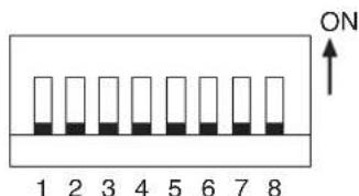
text_image
ON 1 2 3 4 5 6 7 8Step 3. Replace the protective cover.
9. OUTPUTTING LOG DATA (SX-2000SM: DIP Switches 1 and 2 operations)
By writing the SX-2000 system's log data to a CF card in the ".s2l" file format and displaying this data on a PC installed with the SX-2000 Setting Software, the data can be output as an Excel CSV file. The log data includes 2 types of data: Operation log data that contains all logs and Failure log data that contains only failure logs. Both data are saved to a CF card with a file name "Sx2kOp**.s2l" for the Operation log data and "Sx2kFa**.s2l" for the Failure log data automatically assigned. ("**" represents a number from 00 to 99 indicating the order in which the logs have been saved. If more than 100 files are saved, the oldest files are overwritten in chronological order.)
The newness or oldness of a file may be ascertained by checking its date. Shown below is the procedure for writing the SX-2000SM's log data to the CF card.
Notes
- When storing log data on a CF card, confirm in advance that it has at least 15 megabytes of free space.
- Do not operate the DIP switch while the CF card access indicator inside the protective cover is flashing.
- Reactivating the SX-2000SM erases the log data temporarily stored in SX-2000SM memory.
So, when storing log data on a CF card, be sure to perform that before reactivating the SX-2000SM. - The SX-2000SM operates on the current setting data until restarted even if the CF card has been removed from the SX-2000SM for reading log data.
• Operation log data is recorded every hour. - Failure log data is recorded within 100 seconds after a failure has occurred.
Step 1. Remove the protective cover on the SX-2000SM's front panel by removing the screws securing it using a Phillips screwdriver.
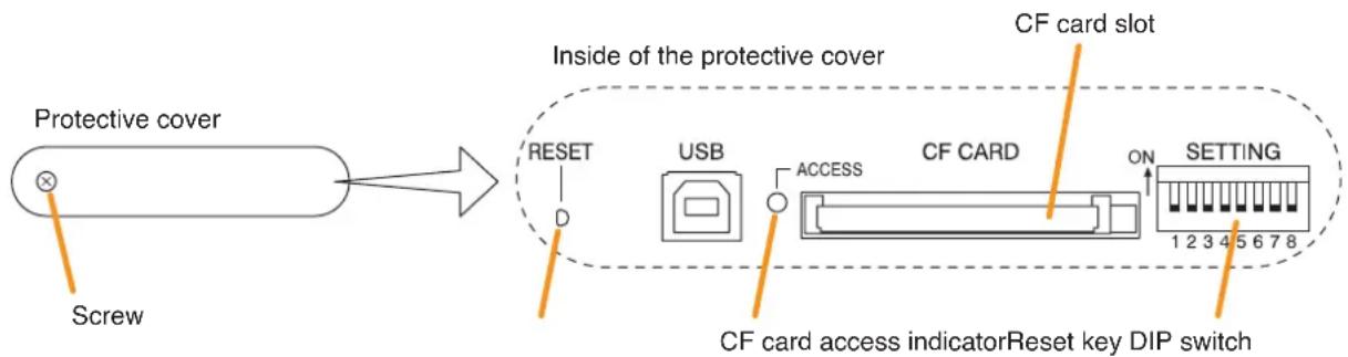
flowchart
graph LR
    A["Protective cover"] --> B["Inside of the protective cover"]
    B --> C["CF card slot"]
    C --> D["Setting"]
    B --> E["RESET"]
    B --> F["USB"]
    B --> G["ACCESS"]
    B --> H["CF CARD"]
    B --> I["ON"]
    B --> J["1 2 3 4 5 6 7 8"]
    B --> K["Screw"]
Step 2. Set DIP switch 1 to ON. Log data is saved to the CF card at this time.
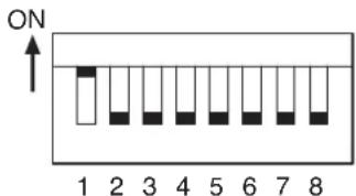
text_image
ON 1 2 3 4 5 6 7 8Note: DIP switch 1 is set to OFF by default.
Step 3. Confirm that the CF card access indicator has gone off, then set DIP switch 1 to the OFF position.

text_image
ON 1 2 3 4 5 6 7 8Step 4. Set DIP switch 2 to ON. Access to the CF card stops, allowing the card to be removed.

text_image
ON 1 2 3 4 5 6 7 8Step 5. Remove the CF card from the card slot.
Step 6. Insert the CF card into the PC's card slot and start the SX-2000 Setting Software.
Confirm the log data using the SX-2000 Setting Software.
For details, see the separate Setting Software Instructions, "Utility."
Step 7. Insert the CF card with the saved settings data into the SX-2000SM's CF card slot.
Inserting the CF card causes the buzzer to sound.
Setting DIP switch 2 to OFF in Step 8 stops the buzzer.
Step 8. Set DIP switch 2 to OFF.
The CF card can be inserted.
Note
When changing the setting data, be sure to press the Reset key to restart the SX-2000 system after turning off DIP switch 2.
Reactivating the system stops broadcasts currently in progress.
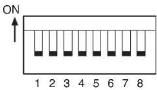
text_image
ON 1 2 3 4 5 6 7 8Step 9. Replace the protective cover.
10. FAILURE INDICATIONS
10.1. SX-2000SM

text_image
FAULT GENERAL indicator CPU indicator SX LINK indicator SX-2000SM TCA EC-2000 SM| Failure Indication Description | |
| or General indicator light failure is detected in the system. | |
| CPU indicator lights yellow. | CPU A failure is detected in the SX-2000SM. |
| SX Link indicator flashes yellow. | SX LINK Both of the rear panel-mounted SX link terminals A and B are unconnected. |
10.2. SX-2000AI and SX-2100AI
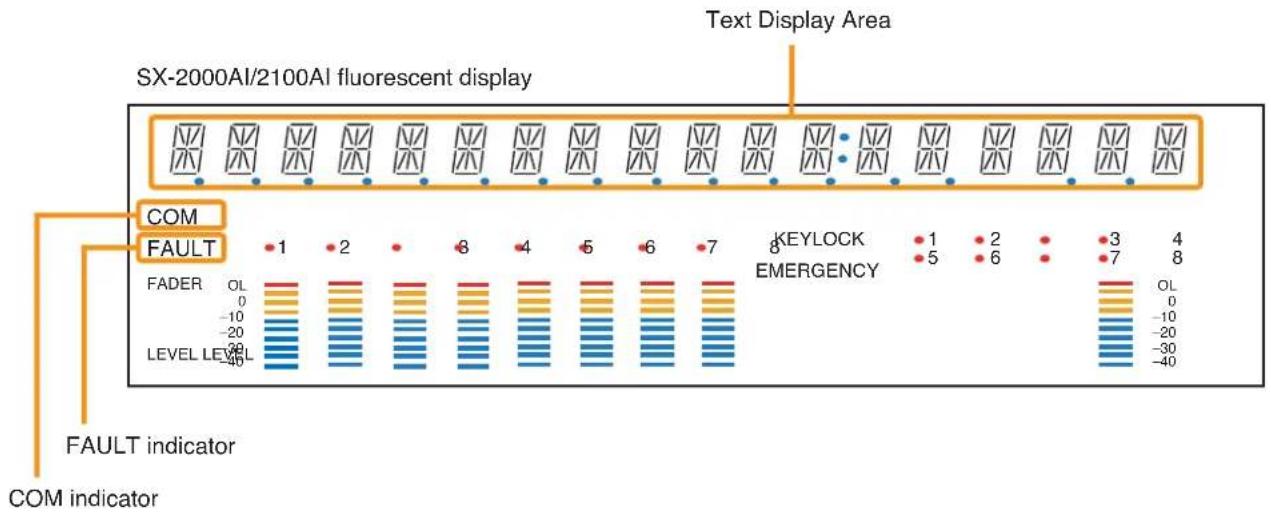
text_image
SX-2000AI/2100AI fluorescent display Text Display Area COM FAULT FADER OL 0 -10 -20 LEVEL LEVEL -40 KEYLOCK 1 2 3 4 EMERGENCY 5 6 7 8 FAULT indicator COM indicator[Failure Indications on the Default Display Screen]
| Failure Indication Description | ||
| • "AI-xx UNLINKED" indication displayed in the text display area. | AI-xx UNLINKED | Not correctly recognized by SX-2000SM.Device number may be duplicated. |
| • "AI-xx UNCONFIGURED" indication displayed in the text display area. | AI-xx UNCONFIGURED | Out of setting range. |
| • "AI-xx MISMATCH VER" indication displayed in the text display area. | AI-xx MISMATCH VER | Not compatible with SX-2000SM.Update SX-2000AI, SX-2100AI or SX-2000SM to the latest firmware. |
| • "AI-xx PLEASE RESET" indication displayed in the text display area. | AI-xx PLEASE RESET | Device number changed.Press the reset button inside the protective cover. |
| • "AI-xx *CHECK SLOT *" indication displayed in the text display area. | AI-xx CHECK SLOT * | Incompatible module mounted. Check the rear panel module slot. |
| • "AI-xx ***CPU OFF ***" indication displayed in the text display area. | AI-xx CPU*OFF *** | The general urgency all-call is being made (CPU off state). |
| • "AI-xx *CF ERROR * " indication displayed in the text display area. | AI-xx CF ERROR * | Something is wrong with the inserted CF card. |
| • "AI-xx MAINTENANCE" indication displayed in the text display area. | AI-xx MAINTENANCE | CF card not inserted into the SX-2000SM. |
| • "AI-xx SYSTEM MUTE" indication displayed in the text display area. | AI-xx SYSTEM MUTE | The sound volume on all input channels set by the SX-2000 Setting Software is muted. |
| • "AI-xx *ALL CH OFF * " indication displayed in the text display area. | AI-xx ALL CH OFF * | The sound volume on all input channels adjusted by the front-mounted input volume controls is muted. |
[Error Indications on the Menu Screen]
When the default display screen is displayed, pressing the menu key and then the OK key switches the display to the error indication screen. Errors are displayed as follows. (For details, see the separate Operating Instructions, "SX-2000AI Audio Input Unit" or "SX-2100AI Audio Input Unit.")
| Failure Indication Description | ||
| "COMPONENT ERROR" indication displayed in the text display area."FAULT" indication flashes. | COMPONENT ERROR![TOA D-921F - [Error Indications on the Menu Screen] - 1](/content/2026/06/1214100/images/06ceb154200db75a669fceae4daafc80d5ac2393a9926014dffde6504e29a8bd.jpg) | System equipment or module configuration differs from that set by the SX-2000 Setting Software. |
| "FAULT DETECTED" indication displayed in the text display area."FAULT" indication flashes. | T DETECTED![TOA D-921F - [Error Indications on the Menu Screen] - 2](/content/2026/06/1214100/images/2362decb9f62edf3bef17b5bd525175e8ef25f0dc1d669ca093d8e0f53ce9e76.jpg) | System has failed. |
| "SX LINK COM FAULT" indication displayed in the text display area."COM" indication flashes."FAULT" indication flashes. | NK COM FAULT![TOA D-921F - [Error Indications on the Menu Screen] - 3](/content/2026/06/1214100/images/2aec8853006b9bd396526bc5450b45e4f8ef74b4aca195516927f6834361baf5.jpg) | Communications cannot be established between the SX-2000AI or SX-2100AI and SX-2000SM. |
10.3. SX-2000AO and SX-2100AO

text_image
SX-2000AO/2100AO fluorescent display Text Display Area COM FAULT FADER 1 2 6 4 5 6 7 KEYLOCK EMERGENCY 8 (SX-2100AO only) FADER OL 0 -10 -20 LEVEL LEVEL -40 FAULT indicator COM indicator (OL 0 -10 -20 -30 -40)[Failure Indications on the Default Display Screen]
| Failure Indication Description | ||
| "AO-xx UNLINKED" indication displayed in the text display area. | AO-xx UNLINKED | Not correctly recognized by SX-2000SM.Device number may be duplicated. |
| "AO-xx UNCONFIGURED" indication displayed in the text display area. | AO-xx UNCONFIGURED | Out of setting range. |
| "AO-xx MISMATCH VER" indication displayed in the text display area. | AO-xx MISMATCH VER | Not compatible with SX-2000SM.Update SX-2000AO, SX-2100AO, or SX-2000SM to the latest firmware. |
| "AO-xx PLEASE RESET" indication displayed in the text display area. | AO-xx PLEASE RESET | Device number changed.Press the reset button inside the protective cover. |
| "AO-xx ***CPU OFF***" indication displayed in the text display area. | AO-xx CPU OFF *** | The general urgency all-call is being made (CPU off state). |
| "AO-xx *CF ERROR * " indication displayed in the text display area. | AO-xx CF ERROR * | Something is wrong with the inserted CF card. |
| "AO-xx MAINTENANCE" indication displayed in the text display area. | AO-xx MAINTENANCE | CF card not inserted into the SX-2000SM. |
| "AO-xx * ALL CH OFF * " indication displayed in the text display area. | AO-xx ALL CH OFF * | The sound volume on all output channels adjusted by the front-mounted output volume controls is muted. |
[Error Indications on the Menu Screen]
When the default display screen is displayed, pressing the Menu key and then the OK key switches the display to the error indication screen. Errors are displayed as follows. (For details, see the separate Operating Instructions, "SX-2000AO Audio Output Unit" or "SX-2100AO Audio Output Unit.")
| Failure Indication Description | |
| "COMPONENT ERROR" indication displayed in the text display area."FAULT" indication flashes. | COMPONENT ERRORFAULT |
| "FAULT DETECTED" indication displayed in the text display area."FAULT" indication flashes. | FAULT DETECTEDFAULT |
| "SX LINK COM FAULT" indication displayed in the text display area."COM" indication flashes."FAULT" indication flashes. | SX LINK COM FAULTCOMFAULT |
10.4. SX-2000CI

text_image
SX-2000CI FAULT FAULT Indicator TDA SC-8000 CI| Failure Indication Description | |
| FAULT Indicator lights yellow. ● FAULT | Communications to the SX-2000AO or SX-2100AO are interrupted for 5 seconds or more. |
| FAULT Indicator flashes yellow. ○ FAULT | A failure is detected in the system. |
10.5. SX-2000CO

text_image
SX-2000CO FAULT FAULT Indicator TXA ZX-2000 CO| Failure Indication Description | |
| FAULT Indicator lights yellow. ● FAULT | Communications to the SX-2000AO or SX-2100AO are interrupted for 5 seconds or more. |
FAULT Indicator flashes yellow.  AULT AULT | A failure is detected in the system. |
10.6. RM-200SF and RM-200SA

text_image
RM-200SF top TOA RM-200SF Failure Indicator M1.5 GF CPU 3000x Failure Indicator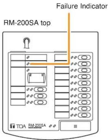
text_image
RM-200SA top Failure Indicator TOA RM-200SA| Failure Indication Description | |
| Failure indicator lights yellow. [WHZ] | Communications with the SX-2000AI or SX-2100AI to which the microphone is connected are interrupted for 5 seconds or more. |
 | A failure is detected in the system.Failure indicator flashes yellow. |
11. SPECIFICATIONS
11.1. SX-2000SM System Manager
| Power Source Usable power supply unit: VX-200PS24 V DC (operational range: 20 V – 40 V DC)Two power inputs construction enables redundant power supply. | |
| Current Consumption Under 1.1 A (maximum value in the power operating range)Under 0.8 A (when operated on 24 V DC) | |
| Indication/Operation SX link indicator: 2LAN indicator: 1Mode indicator: 3 (EMERGENCY/STANDBY/CPU OFF)Fault indicator: 3 (GENERAL/CPU/SX LINK)Power indicator: 1 (POWER)Run indicator: 1 (RUN)Failure control key: 3 (FAULT ACK/FAULT RESET/LAMP TEST) | |
| SX Link | |
| Network I/F 2 100BASE-TX circuits, RJ45 connector | |
| Matrix System Bus: 16 Priority control: 512 stepsSpecification | Audio input: Max. 64 ch Event log data: Max. 1,000 piecesAudio output: Max. 256 zones Failure log data: 100 piecesContact input: Max. 1416Contact output: Max. 1416 |
| Matrix SystemConfiguration(Maximum number of units) | SX-2000AI/2100AI: 8 in totalSX-2000AO/2100AO: 32 in totalSX-2000CI: 32 (one per SX-2000AO/2100AO)SX-2000CO: 32 (one per SX-2000AO/2100AO)RM-200SF/200SA: 64 in total (up to 8 in total per SX-2000AI/2100AI) |
| Connection Cable/Device | Shielded Category 5 twisted pair cable for LAN (CAT5-STP)(Connect SX-2000AI,SX-2100AI, and SX-2000AO via the switching hub specified by TOA.)Note: This network must be made completely independent from other LAN. |
| Number of CascadedSwitching Hubs | Up to 7 |
| Maximum Cable Distance | 100 m (between this unit and a switching hub or between switching hubs) |
| LAN | |
| Network I/F 1 10BASE-T/100BASE-TX circuit (selectable by automatic recognition),RJ45 connector for maintenance use | |
| Network Protocol | TCP/IP |
| Connection Cable | Shielded Category 5 twisted pair cable for LAN (CAT5-STP) |
| Maximum Cable Distance | 100 m (between this unit and a switching hub or between a switching hub and a PC) |
| Analog Link | |
| Input/Output Connector | Output: 2, RJ45 connector |
| Connection Cable | Shielded Category 5 twisted pair cable for LAN (CAT5-STP)(each one pair of audio wire, CPU OFF, control wire for system reset/start, and connection check wire) |
| Maximum Cable Distance | 800 m (total) |
| DS Link | |
| Usable unit | VX-2000DS |
| Connector/Cable | 2 interfaces, RJ45 Connector,Shielded Category 5 twisted pair cable for LAN (CAT5-STP) |
| Maximum Cable Distance | 5 m |
| Failure Data Input | 3 inputs (ACK/RES/LAMP), no-voltage make contact input,open voltage: 24 V DC, short-circuit current: 2 mA, photo coupler input,removable terminal block (12 pins) |
| Failure Data Output | 4 outputs (CPU FAULT/GENERAL FAULT/CPU OFF/ BUZZER), C contact,no-voltage make contact output, relay contact output (withstand voltage: 40 V DC,control current: 2 – 300 mA), RJ45 connector |
| Control Input | 8 inputs, no-voltage make contact input, open voltage: 24 V DC, short-circuitcurrent: 2 mA, photo coupler input, removable terminal block (12 pins) |
| Control Output 8 outputs, | C contact, no-voltage make contact output: relay contact output (withstand voltage: 40 V DC, control current: 2 – 300 mA), removable terminal block (12 pins) |
| Memory Card Mounting slot: 1 (use of supplied CF card), set data and log data stored | |
| Operating Temperature 0°C to 40°C | |
| Operating Humidity 35% to 80% RH (no condensation) | |
| Finish Panel: Aluminum, black, alumiteCase: Surface-treated steel plate | |
| Dimensions 482 (w) x 44 (h) x 333 (d) mm | |
| Weight | 3.8 kg |
Note: The design and specifications are subject to change without notice for improvement.
- Accessories
CD (SX-2000 Setting Software, Setting Software Instructions, Operating Instructions) ..... 1
CF card 1
Removable terminal plug (4 pins) 1
Removable terminal plug (12 pins) 4
Rack mounting screw with plain washer (5 x 12) 4
Screwdriver 1
CF card adapter 1
Installation Manual (This manual) 1
PLEASE READ THIS MANUAL FIRST!....1
11.2. SX-2000AI Audio Input Unit
| Power Source Usable power | supply unit: VX-200PS24 V DC (operational range: 20 V – 40 V DC)Two power inputs construction enables redundant power supply. |
| Current Consumption Under | 1.82 A (maximum value in the power operating range)Under 13.5 A (when operated on 24 V DC)Note: Excludes current consumption of the external equipment powered by the unit. |
| Indication 18 alphanumeric characters, Level indication (8 inputs, monitor),Status indicators, Power indicator, Standby indicator, CPU OFF indicator | |
| Operation Function keys, Input volume controls, Monitor volume control, Channel keys,Monitor ON/OFF keys, Menu screen operation keys (5) | |
| Audio Input 8 inputs, module construction (max. 4 modules, modules optional),monitoring possible using built-in speaker | |
| Audio Input Characteristic Sampling frequency: 48 kHz | |
| No. of Connectable Max. 8RM-200SA Units | |
| Power Supply to Up to a total of 8 A.Remote Microphone | |
| SX Link | |
| Network I/F 2 100BASE-TX circuits, RJ45 connector, decentralized installation possible | |
| Connection Cable/Device Shielded Category 5 twisted pair cable for LAN (CAT5-STP)To be connected via the switching hub specified by TOANote: This network must be made completely independent from other LAN. | |
| Maximum Cable Distance 100 m (between this unit and a switching hub) | |
| Analog Link | |
| Input/Output Connector | Input: 1 input, RJ45 connectorOutput: 1 output, RJ45 connector |
| Connection Cable | Shielded Category 5 twisted pair cable for LAN (CAT5-STP)(each one pair of audio wire, CPU OFF, control wire for system reset/start,and connection check wire) |
| Maximum Cable Distance 800 m (total) | |
| Operating Temperature | 0°C to 40°C |
| Operating Humidity | 35% to 80% RH (no condensation) |
| Finish | Panel: Aluminum, black, alumiteCase: Surface-treated steel plate |
| Dimensions | 482 (w) x 88.4 (h) x 349 (d) mm |
| Weight | 7 kg |
Note: The design and specifications are subject to change without notice for improvement.
- Accessories
Removable terminal plug (4 pins) 1
Rack mounting screw with plain washer (5 x 12) .... 4
- Optional products
Remote Microphone Interface Modules: SX-200RM
Microphone/Line Input Module: D-921E, D-921F, D-922E, D-922F
Stereo Input Module: D-936R
Note: Modules other than described above cannot be used.
11.3. SX-2100AI Audio Input Unit
| Power Source Usable power | supply unit: VX-200PS24 V DC (operational range: 20 V – 40 V DC)Two power inputs construction enables redundant power supply. |
| Current Consumption Under | 2.01 A (maximum value in the power operating range)Under 1.50 A (when operated on 24 V DC)Note: Excludes current consumption of the external equipment powered by the unit. |
| Indication 18 alphanumeric characters, Level indication (8 inputs, monitor),Status indicators, Power indicator, Standby indicator, CPU OFF indicator | |
| Operation Function keys, Input volume controls, Monitor volume control, Channel keys,Monitor ON/OFF keys, Menu screen operation keys (5) | |
| Audio Input 8 inputs, module construction (max. 4 modules, modules optional),monitoring possible using built-in speaker | |
| Audio Input Characteristic Sampling frequency: 48 kHz | |
| No. of Connectable Max. 8RM-200SA Units | |
| Power Supply to Up to a total of 8 A.Remote Microphone | |
| SX Link | |
| Network I/F 2 100BASE-TX circuits, RJ45 connector, decentralized installation possible | |
| Connection Cable/Device Shielded Category 5 twisted pair cable for LAN (CAT5-STP)To be connected via the switching hub specified by TOANote: This network must be made completely independent from other LAN. | |
| Maximum Cable Distance 100 m (between this unit and a switching hub) | |
| Analog Link | |
| Input/Output Connector Input: 1 input, RJ45 connectorOutput: 1 output, RJ45 connector | |
| Connection Cable Shielded Category 5 twisted pair cable for LAN (CAT5-STP)(each one pair of audio wire, CPU OFF, control wire for system reset/start,and connection check wire) | |
| Maximum Cable Distance 800 m (total) | |
| Control Input 16 inputs, no-voltage make contact input, open voltage: Under 40 V DC,short-circuit current: 2 mA, photo coupler input,removable terminal block (16 pins) | |
| Control Output | 16 outputs, A contact (changeable to B contact),no-voltage make contact output: relay contact output(withstand voltage: 40 V DC, control current: 2 – 300 mA),removable terminal block (16 pins) |
| Operating Temperature | 0°C to 40°C |
| Operating Humidity | 35% to 80% RH (no condensation) |
| Finish | Panel: Aluminum, black, alumiteCase: Surface-treated steel plate |
| Dimensions | 482 (w) x 88.4 (h) x 349 (d) mm |
| Weight | 7.2 kg |
Note: The design and specifications are subject to change without notice for improvement.
- Accessories
Removable terminal plug (4 pins) 1
Removable terminal plug (16 pins) 4
Rack mounting screw with plain washer (5 x 12) .... 4
- Optional products
Remote Microphone Interface Modules: SX-200RM
Microphone/Line Input Module: D-921E, D-921F, D-922E, D-922F
Stereo Input Module: D-936R
Note: Modules other than described above cannot be used.
11.4. SX-2000AO Audio Output Unit
| Power Source Usable power | supply unit: VX-200PS24 V DC (operational range: 20 V - 40 V DC)Two power inputs construction enables redundant power supply. |
| Current Consumption Under | 1.2 A (maximum value in the power operating range)Under 0.79 A (when operated on 24 V DC)Note: Excludes current consumption of the external equipment powered by the unit. |
| Indication 18 alphanumeric characters, Level indication (8 outputs, monitor),Run indicator, Power indicator, Standby indicator, CPU OFF indicator | |
| Operation Function keys, Output volume controls, Monitor volume control,Channel keys, Monitor ON/OFF key, Menu screen operation keys | |
| Audio Output | 8 outputs, 0 dB*, suitable load: 600 Ω or above, electronically-balanced output(changeable into transformer-balanced output), removable terminal block (12 pins), monitoring possible using built-in speaker |
| Audio Output Characteristic | Frequency response: 20 Hz - 20 kHzSampling frequency: 48 kHzD/A converter: 24 bit |
| Emergency Audio Input 1 input (H, C, E), signals switched by relay, removable terminal block (3 pins),Emergency audio input is output from all audio output terminals when the power or a 24 V emergency cutoff input is cut off. | |
| 24 V Emergency Cutoff 1 input, input current: under 5 mA, removable terminal block (2 pins),Input disabled using DIP switch | |
| SX Link | |
| Network I/F 2 100BASE-TX | circuits, RJ45 connector, decentralized installation possible |
| Connection Cable/Device Shielded | Category 5 twisted pair cable for LAN (CAT5-STP)To be connected via the switching hub specified by TOANote: This network must be made completely independent from other LAN. |
| Maximum Cable Distance 100 m (between this unit and a switching hub) | |
| Analog Link | |
| Input/Output Connector Input | 1 input, RJ45 connectorOutput: 1 output, RJ45 connector |
| Connection Cable Shielded | Category 5 twisted pair cable for LAN (CAT5-STP)(each one pair of audio wire, CPU OFF, control wire for system reset/start,and connection check wire) |
| Maximum Cable Distance 800 m (total) | |
| CI/CO Link | |
| Usable unit | SX-2000CI or SX-2000CO |
| Connector/Cable | 1 interface, RJ45 Connector,Shielded Category 5 twisted pair cable for LAN (CAT5-STP) |
| Maximum Cable Distance 800 m | |
| Control Input | 8 inputs, no-voltage make contact input, open voltage: Under 40 V DC,short-circuit current: 2 mA, photo coupler input,removable terminal block (6 pins) |
| Control Output | 8 outputs, C contact, no-voltage make contact output: relay contact output(withstand voltage: 40 V DC, control current: 2 - 300 mA),removable terminal block (6 pins) |
| Operating Temperature | 0°C to 40°C |
| Operating Humidity | 35% to 80% RH (no condensation) |
| Finish | Panel: Aluminum, black, alumiteCase: Surface-treated steel plate |
| Dimensions | 482 (w) x 88.4 (h) x 349 (d) mm |
| Weight | 6.2 kg |
* 0 dB = 1 V
Note: The design and specifications are subject to change without notice for improvement.
- Accessories
Removable terminal plug (12 pins) 2
Removable terminal plug (6 pins) 8
Removable terminal plug (4 pins) 1
Removable terminal plug (3 pins) 1
Removable terminal plug (2 pins) 1
Rack mounting screw with plain washer (5 x 12) .... 4
- Optional product
Line transformer: IT-450
11.5. SX-2100AO Audio Output Unit
| Power Source Usable power | supply unit: VX-200PS24 V DC (operational range: 20 V – 40 V DC)Two power inputs construction enables redundant power supply. |
| Current Consumption Under | 1.7 A (maximum value in the power operating range)Under 1.2 A (when operated on 24 V DC)Note: Excludes current consumption of the external equipment powered by the unit. |
| Indication 18 alphanumeric characters, Level indication (8 outputs, monitor),Run indicator, Power indicator, Standby indicator, CPU OFF indicator | |
| Operation Function keys, Output volume controls, Monitor volume control,Channel keys, Monitor ON/OFF key, Menu screen operation keys | |
| PA Link | |
| Usable Amplifier VP-2064, VP-2122, VP-2241 or VP-2421(VP-200VX is required for each amplifier) | |
| Connector/Cable RJ45 Connector, Shielded Category 5 twisted pair cable for LAN (CAT5-STP) | |
| Audio Output Characteristic | 8 outputs and standby AMP, 0 dB*, suitable load: 600 Ω or above,electronically balanced, monitoring possible using built-in speakerFrequency response: 20 Hz – 20 kHzSampling frequency: 48 kHzD/A converter: 24 bit |
| Maximum Cable Distance 5 m | |
| Local Audio input | |
| Connector/Cable 2 inputs, RJ45 Connector,Shielded Category 5 twisted pair cable for LAN (CAT5-STP) | |
| Audio Input 0 dB*, 10 kΩ, electronically balanced | |
| Audio input Frequency response: 20 Hz – 20 kHzCharacteristic Sampling frequency: 48 kHzA/D converter: 24 bit | |
| Control Input 2 inputs, no-voltage make contact input, open voltage: 12 V DC,short-circuit current: 2 mA, photo coupler input | |
| SX Link | |
| Network I/F | 2 100BASE-TX circuits, RJ45 connector, decentralized installation possible |
| Connection Cable/Device | Shielded Category 5 twisted pair cable for LAN (CAT5-STP)To be connected via the switching hub specified by TOA.Note: This network must be made completely independent from other LAN. |
| Maximum Cable Distance 100 m (between this unit and a switching hub) | |
| Analog Link | |
| Input/Output Connector | Input: 1 input, RJ45 connectorOutput: 1 output, RJ45 connector |
| Connection Cable | Shielded Category 5 twisted pair cable for LAN (CAT5-STP)(each one pair of audio wire, CPU OFF, control wire for system reset/start,and connection check wire) |
| Maximum Cable Distance 800 m (total) | |
| DS Link | |
| Usable unit VX-2000DS | |
| Connector/Cable 2 interfaces | RJ45 Connector,Shielded Category 5 twisted pair cable for LAN (CAT5-STP) |
| Maximum Cable Distance | 5 m |
| CI/CO Link | |
| Usable unit SX-2000CI or SX-2000CO | |
| Connector/Cable 1 interface | RJ45 Connector,Shielded Category 5 twisted pair cable for LAN (CAT5-STP) |
| Maximum Cable Distance | 800 m |
| Speaker Line Failure Detection Section | |
| Connector/Cable Removable terminal blocks, SP/AMP: 8 pins per terminal block,STANDBY AMP: 2 pins, AWG 16 – 24 | |
| Maximum Input Voltage 100 Vrms, 5 Armsand Current | |
| Fault Detection System Short circuit, open circuit, ground fault | |
| Method Impedance or End of line | |
| End of line | In Case of Normal: Terminated by 470 kΩ between the speaker line and the shieldIn Case of Open: Opened between the speaker line and the shield |
| Impedance Minimum Load: 2 kΩ (5 W) at 100 V line | |
| Control Input 8 inputs, no-voltage make contact input, open voltage: Under 40 V DC,short-circuit current: 2 mA, photo coupler input,removable terminal block (6 pins) | |
| Control Output 8 outputs, C | contact, no-voltage make contact output: relay contact output(withstand voltage: 40 V DC, control current: 2 – 300 mA),removable terminal block (6 pins) |
| Operating Temperature 0°C to 40°C | |
| Operating Humidity 35% to 80% RH (no condensation) | |
| Finish | Panel: Aluminum, black, alumiteCase: Surface-treated steel plate |
| Dimensions | 482 (w) x 88.4 (h) x 349 (d) mm |
| Weight | 7.1 kg |
* 0 dB = 1 V
Note: The design and specifications are subject to change without notice for improvement.
- Accessories
Removable terminal plug (8 pins) 4
Removable terminal plug (6 pins) 8
Removable terminal plug (4 pins) 1
Removable terminal plug (2 pins) 1
Rack mounting screw with plain washer (5 x 12) 4
11.6. SX-2000CI Control Input Unit
| Power Source 24 V DC (operational range: 20 – 40 V DC),2 channels of power inputs for accepting redundant power supply | |
| Current Consumption Under | 0.7 A (maximum value in the power operating range)Under 0.55 A (at 24 V DC operation) |
| Indication Control Input indicators, Power indicator, CPU-OFF indicator, Fault indicator | |
| Control Input 32 inputs, no-voltage make contacts, open voltage: 24 V DC,short-circuit current: 2 mA, photo coupler inputs,removable terminal blocks (16P x 4) | |
| Surveillance Section for the Control Input Lines | Connection resistance to make the function inactive: 20 kΩ ±5%Connection resistance to make the function active:10 kΩ ±5%Connection cable: Twisted pair cable (shielded type is recommended)Maximum cable distance: 10 m |
| CI/CO Link | |
| Input/Output Input: 1 channel, RJ45 connectorOutput: 1 channel, RJ45 connector | |
| Connection Cable Shielded | Category 5 twisted pair cable for LAN (CAT5-STP)(each one pair of data wire and control wire) |
| Maximum Cable Distance 800 m | |
| 24 V DC Output section | |
| Connector Input: 1 input, RJ45 connectorOutput: 1 output, RJ45 connector | |
| Connection Cable | Removable terminal block (2P) |
| Maximum Feeing Current | 100 mA |
| Output Voltage | 24 V DC within ±10% |
| Operating Temperature | 0°C to 40°C |
| Operating Humidity | 35% to 80% RH (no condensation) |
| Finish | Panel: Aluminum, black, alumiteCase: Surface-treated steel plate |
| Dimensions 482 (w) x 44 (h) x 331.5 (d) mm | |
| Weight | 3.6 kg |
Note: The design and specifications are subject to change without notice for improvement.
- Accessories
Removable terminal plug (16 pins) 4
Removable terminal plug (4 pins) 1
Removable terminal plug (2 pins) 1
Rack mounting screw with plain washer (5 x 12) .... 4
11.7. SX-2000CO Control Output Unit
| Power Source 24 V DC (operational range: 20 V – 40 V DC),2 channels of power inputs for accepting redundant power supply | |
| Current Consumption Under | 0.34 A (maximum value in the power operating range)Under 0.29 A (at 24 V DC operation) |
| Indication Control Output indicators, Power indicator, CPU-OFF indicator, Fault indicator | |
| Control Output 32 outputs, no-voltage make contacts, replay contact outputs(withstand voltage: 40 V DC, control current: 2 – 300 mA),removable terminal blocks (6P x 16) | |
| CI/CO Link | |
| Input/Output Input: 1 channel, RJ45 connectorOutput: 1 channel, RJ45 connector | |
| Connection Cable Shielded | Category 5 twisted pair cable for LAN (CAT5-STP)(each one pair of data wire and control wire) |
| Maximum Cable Distance 800 m | |
| Operating Temperature 0°C to 40°C | |
| Operating Humidity 35% to 80% RH (no condensation) | |
| Finish Panel: Aluminum, black, alumiteCase: Surface-treated steel plate | |
| Dimensions 482 (w) x 44 (h) x 331.5 (d) mm | |
| Weight | 3.6 kg |
Note: The design and specifications are subject to change without notice for improvement.
- Accessories
Removable terminal plug (6 pins) 16
Removable terminal plug (4 pins) 1
Rack mounting screw with plain washer (5 x 12) .... 4
11.8. RM-200SF Fireman's Microphone
| Power Source 24 V DC (operating range: 15 – 40 V DC, supplied from the SX-2000 system.) | |
| Current Consumption 240 mA or less | |
| Audio Output 0 dB*, transformer-balanced | |
| Distortion 1% or less | |
| Frequency Response 200 Hz – 15 kHz | |
| S/N Ratio 55 dB or more | |
| Microphone Unidirectional dynamic microphone with talk key, AGC (ON/OFF switchable), Microphone element failure detectable by using a built-in oscillator | |
| Chime Built-in (PCM sound source), Monitoring available with a built-in speaker. | |
| Volume Control Microphone volume control, Monitor speaker volume control, Chime volume control (using the software) | |
| Connection Cable Main line: Shielded CPEV cable (each one pair of Audio line, Data line, Monitor/control line, and power supply line) or Shielded Category 5 twisted pair cable for LAN (CAT5-STP), M3 screw terminal | |
| Maximum Cable Distance 800 m (total) | |
| No. of Connectable Max. 5 units RM-210 Units | |
| Monitor Speaker Built-in type | |
| Operation | Emergency key, Function keys, CPU switch, Reset switch |
| Indicator | Status indicators, Power indicator, Failure indicator, CPU indicator, Selection indicators, Microphone indicator, Broadcast status indicator |
| Operating Temperature | 0°C to 40°C |
| Operating Humidity 35% to 80% RH (no dew condensation) | |
| Finish | ABS resin, blueish gray (PANTONE 538 or its equivalent) |
| Dimensions | 200 (w) x 215 (h) x 95 (d) mm (including the Wall Mounting Bracket) |
| Weight | 1.48 kg |
| Applicable Box | YS-11A |
* 0 dB = 1 V
Note: The design and specifications are subject to change without notice for improvement.
- Accessories
EMC clamp 1
Wall mounting bracket unit 1
4 x 25 tapping screw for wooden wall .... 2
M3.5 x 20 screw for electrical box 2
- Optional product
Remote Microphone Extension unit: RM-210
11.9. RM-200SA Remote Microphone
| Power Source 24 V DC (operating range: 15 – 40 V DC, supplied from the SX-200RM) orDC input power supply connector (when the optional AD-246AC adapter used).Usable DC power supply plug: 5.5 mm outer diameter, 2.1 mm inner diameter,9.5 mm long, and non-polarity type. | |
| Current Consumption Under | 240 mA |
| Audio Output 0 dB*, 600 Ω, balanced | |
| External Microphone Input | -40 dB*, 2.2 kΩ, unbalanced, mini jack |
| Distortion Under 1% | |
| Frequency Response 100 Hz – 20 kHz | |
| S/N Ratio Over 60 dB | |
| Microphone Undirectional electret condenser microphone with AGC (ON/OFF selectable) | |
| Chime Built inside (PCM sound source), monitoring possible with built-in speaker | |
| Volume Control Microphone volume control, monitor speaker volume control,chime (adjustable using the SX-2000 Setting Software) | |
| Connection Cable Main line: Shielded CPEV cable (1 pair of audio wire + 1 pair of data wire +1 pair of monitor/control wire + 1 pair of power supply wire) orShielded Category 5 twisted pair cable for LAN (CAT5-STP)Branch line: Shielded Category 5 twisted pair cable for LAN (CAT5-STP),RJ45 connector | |
| Maximum Cable Distance 800 m | |
| No. of Connectable Max. 4 unitsRM-210 Units | |
| Monitor Speaker Built inside | |
| Operation | Function keys, General urgency all-call key (covered), Talk key |
| Indicator | Power indicator, Failure indicator, Status indicators,Selection indicators, Microphone indicator |
| Operating Temperature | 0°C to 40°C |
| Operating Humidity 35% to | 80% RH (no condensation) |
| Finish | ABS resin, blueish gray |
| Dimensions | 190 (w) x 76.5 (h) x 215 (d) mm (excluding microphone) |
| Weight | 880 g |
* 0 dB = 1 V
Note: The design and specifications are subject to change without notice for improvement.
- Optional products
AC Adapter: AD-246
Wall-Mounting Bracket: WB-RM200
11.10. RM-210 Remote Microphone Extension
| Power Source | Supplied from RM-200SA |
| Current Consumption | 80 mA max. (in terms of RM-200SA's or RM-200SF's DC power input) |
| Operation | Function keys |
| Indication | Broadcast status indicators, Selection indicators |
| Finish | ABS resin, blueish gray (PANTONE 538 or its equivalent) |
| Dimensions | 110 (w) x 76.5 (h) x 215 (d) mm |
| Weight | 350 g |
Note: The design and specifications are subject to change without notice for improvement.
- Accessories
Extension cable 1
Linkage bracket A 2
Linkage bracket B 1
Screw for linkage bracket 12
- Optional product
Remote Microphone Extension unit: RM-210
Wall-Mounting Bracket: WB-RM200
11.11. RM-200RJ Terminal Unit
| Applied Voltage | 40 V or less |
| Withstand Current | 1 A |
| DC Voltage Monitoring Section | Monitor terminals: Terminal No. 7 (+) and Terminal No. 8 (−), Extinguish voltage: 14 V or less, Lighting voltage: 21 V or more, Indicator ON/OFF switchable |
| Connector | RJ45 connector x 1 |
| Terminal Block | M3 screw terminal (10P), Barrier spacing: 6.62 mm |
| Operating Temperature | 0°C to 40°C |
| Operating Humidity | 35% to 80% RH (no condensation) |
| Finish | Surface-treated steel plate, black, paint |
| Dimensions | 84 (w) x 116 (h) x 25.7 (d) mm |
| Weight | 250 g |
Note: The design and specifications are subject to change without notice for improvement.
11.12. SX-200RM Remote Microphone Interface Module
| Audio Input 2 inputs, 0 dB*, | RJ45 connector |
| Audio Input Characteristic Sampling frequency: 48 kHzA/D converter: 24 bits | |
| Power Feed Max. 1 A per connector | |
| Gain Control Audio input (0 to +12 dB) | |
| Finish Panel: Pre-coated steel plate, black (30% gloss) | |
| Dimensions 35 (w) x119.5 (h) x 178.4 (d) mm | |
| Weight | 190 g |
* 0 dB = 1 V
Note: The design and specifications are subject to change without notice for improvement.
11.13. D-921E Microphone/Line Input Module
| Input 2 channels, Mic/Line changeableMic: -50/-36 dB*, 4.7 kΩ, electronically-balanced,3-pin removable terminal blockLine: -10/+4 dB*, 10 kΩ, electronically-balanced,3-pin removable terminal blockPhantom power supply (+12 V, can be used when set for the microphone)Ground lift switch | |
| A/D Converter 24 bits | |
| Sampling Frequency 48 kHz | |
| Frequency Response 20 Hz – 20 kHz, ±1 dB (+4 dB* input) | |
| Dynamic Range Over 100dB (IHF-A weighted) (+4 dB* input) | |
| Total Harmonic Distortion Under 0.05% (+4 dB* input) | |
| Finish Panel: Pre-coated steel plate, black (30% gloss) | |
| Dimensions 35 (w) x 119.5 (h) x 178.4 (d) mm | |
| Weight | 140 g |
* 0 dB = 0.775 V
Note: The design and specifications are subject to change without notice for improvement.
- Accessories
3-pin removable terminal plug (preinstalled on the unit) ...... 2
11.14. D-921F Microphone/Line Input Module
| Input 2 channels, Mic/Line changeableMic: -50/-36 dB*, 4.7 kΩ, electronically-balanced,equivalent to XLR-3-31 typeLine: -10/+4 dB*, 10 kΩ, electronically-balanced,equivalent to XLR-3-31 typePhantom power supply (+12 V, can be used when set for the microphone)Ground lift switch | |
| A/D Converter 24 bits | |
| Sampling Frequency 48 kHz | |
| Frequency Response 20 Hz – 20 kHz, ±1 dB (+4 dB* input) | |
| Dynamic Range Over 100dB (IHF-A weighted) (+4 dB* input) | |
| Total Harmonic Distortion Under 0.05% (+4 dB* input) | |
| Finish Panel: Pre-coated steel plate, black (30% gloss) | |
| Dimensions 35 (w) x 119.5 (h) x 178.4 (d) mm | |
| Weight | 150 g |
* 0 dB = 0.775 V
Note: The design and specifications are subject to change without notice for improvement.
11.15. D-922E Microphone/Line Input Module
| Input | 2 channels, -50/-36/-10/+4 dB* (Selectable with the DIP switch), 4.7 kΩ, electronically-balanced, 3-pin removable terminal block Phantom power supply (+12 V, can be set with the DIP switch) Ground lift switch (can be set with the DIP switch) |
| A/D Converter 20 bits | |
| Sampling Frequency 48 kHz | |
| Frequency Response 20 Hz – 20 kHz, ±1 dB (+4 dB* input) | |
| Dynamic Range Over 85 dB (IHF-A weighted) (+4 dB* input) | |
| Total Harmonic Distortion Under 0.2% (+4 dB* input) | |
| Finish Panel: Pre-coated steel plate, black (30% gloss) | |
| Dimensions 35 (w) x 119.5 (h) x 178.4 (d) mm | |
| Weight | 125 g |
* 0 dB = 0.775 V
Note: The design and specifications are subject to change without notice for improvement.
- Accessories
3-pin removable terminal plug (preinstalled on the unit) ...... 2
11.16. D-922F Microphone/Line Input Module
| Input | 2 channels, -50/-36/-10/+4 dB* (Selectable with the DIP switch), 4.7 kΩ, electronically-balanced, equivalent to XLR-3-31 type Phantom power supply (+12 V, can be set with the DIP switch) Ground lift switch (can be set with the DIP switch) |
| A/D Converter 20 bits | |
| Sampling Frequency 48 kHz | |
| Frequency Response 20 Hz – 20 kHz, ±1 dB (+4 dB* input) | |
| Dynamic Range Over 85 dB (IHF-A weighted) (+4 dB* input) | |
| Total Harmonic Distortion Under 0.2% (+4 dB* input) | |
| Finish Panel: Pre-coated steel plate, black (30% gloss) | |
| Dimensions 35 (w) x 119.5 (h) x 178.4 (d) mm | |
| Weight | 135 g |
* 0 dB = 0.775 V
Note: The design and specifications are subject to change without notice for improvement.
11.17. D-936R Stereo Input Module
| Input Monaural input x 2, -1 | 10 dB*, 10 kΩ, RCA pin jack |
| A/D Converter 24 bits | |
| Sampling Frequency 48 kHz | |
| Frequency Response 20 Hz | -20 kHz, ±1 dB (+4 dB* input) |
| Dynamic Range Over 100dB (IHF-A weighted) | |
| Total Harmonic Distortion Under 0.05% | |
| Finish Panel: Pre-coated steel plate, black (30% gloss) | |
| Dimensions 35 (w) x 119.5 (h) x 178.4 (d) mm | |
| Weight | 145 g |
* 0 dB = 0.775 V
Note: The design and specifications are subject to change without notice for improvement.
11.18. VP-2064 Power Amplifier 4 x 60 W
| Power Source | 28 V DC (operating range: 20 – 40 V DC)M4 screw terminal, distance between barriers: 12 mm |
| Current Consumption (EN60065) | 4.8 A in total |
| Rated Output Power | 60 W x 4 (at min. resistive and max. capacitive load) |
| Output Power(at AC Mains: 195.5 V) | 45 W x 4 (at min. resistive and max. capacitive load) |
| Output Voltage | 100 V (70 V, 50 V: selectable by internal wiring change) |
| Minimum Resistive Load | 167 Ω (at 100 V), 83 Ω (at 70 V), 41 Ω (at 50 V) |
| Maximum Capacitive Load | 0.125 μF (at 100 V), 0.25 μF (at 70 V), 0.5 μF (at 50 V) |
| Number of Channels | 4 |
| Input | Specified by input module VP-200VX |
| Number of Module Slots | 4 |
| Usable Module | VP-200VX |
| Output | Power amplifier output (speaker line):M3.5 screw terminal, distance between barriers: 8.8 mm |
| Frequency Response | 40 Hz – 16 kHz, ±3 dB (at 1/3 rated output) |
| Distortion | Under 1% (at rated output, 1 kHz) |
| Signal-to-Noise Ratio | Over 80 dB |
| Panel Indicator | Channel power indicator: 4 channels, dual colour LEDOverheat indicator: Yellow LED |
| Operating Temperature | 0 to +40°C |
| Finish | Panel: Surface-treated steel plate, black (30% gloss), paint |
| Dimensions | 482 (w) x 88.4 (h) x 340.5 (d) mm |
| Weight | 11.2 kg |
Note: The design and specifications are subject to change without notice for improvement.
- Accessories
Rack mounting screw (5 x 12) 4
Fiber washer 4
11.19. VP-2122 Power Amplifier 2 x 120 W
| Power Source | 28 V DC (operating range: 20 – 40 V DC)M4 screw terminal, distance between barriers: 12 mm |
| Current Consumption (EN60065) | 4.8 A in total |
| Rated Output Power | 120 W x 2 (at min. resistive and max. capacitive load) |
| Output Power(at AC Mains: 195.5 V) | 90 W x 2 (at min. resistive and max. capacitive load) |
| Output Voltage | 100 V (70 V, 50 V: selectable by internal wiring change) |
| Minimum Resistive Load | 83 Ω (at 100 V), 41 Ω (at 70 V), 21 Ω (at 50 V) |
| Maximum Capacitive Load | 0.25 μF (at 100 V), 0.5 μF (at 70 V), 1 μF (at 50 V) |
| Number of Channels | 2 |
| Input | Specified by input module VP-200VX |
| Number of Module Slots | 2 |
| Usable Module | VP-200VX |
| Output | Power amplifier output (speaker line):M3.5 screw terminal, distance between barriers: 8.8 mm |
| Frequency Response | 40 Hz – 16 kHz, ±3 dB (at 1/3 rated output) |
| Distortion | Under 1% (at rated output, 1 kHz) |
| Signal-to-Noise Ratio | Over 80 dB |
| Panel Indicator | Channel power indicator: 2 channels, dual colour LEDOverheat indicator: Yellow LED |
| Operating Temperature | 0 to +40°C |
| Finish | Panel: Surface-treated steel plate, black (30% gloss), paint |
| Dimensions | 482 (w) x 88.4 (h) x 340.5 (d) mm |
| Weight | 9.1 kg |
Note: The design and specifications are subject to change without notice for improvement.
- Accessories
Rack mounting screw (5 x 12) 4
Fiber washer 4
11.20. VP-2241 Power Amplifier 1 x 240 W
| Power Source | 28 V DC (operating range: 20 – 40 V DC)M4 screw terminal, distance between barriers: 12 mm |
| Current Consumption (EN60065) | 4.8 A |
| Rated Output Power | 240 W (at min. resistive and max. capacitive load) |
| Output Power(at AC Mains: 195.5 V) | 180 W (at min. resistive and max. capacitive load) |
| Output Voltage | 100 V (70 V, 50 V: selectable by internal wiring change) |
| Minimum Resistive Load | 41 Ω (at 100 V), 21 Ω (at 70 V), 10 Ω (at 50 V) |
| Maximum Capacitive Load | 0.5 μF (at 100 V), 1 μF (at 70 V), 1 μF (at 50 V) |
| Number of Channels | 1 |
| Input | Specified by input module VP-200VX |
| Number of Module Slots | 1 |
| Usable Module | VP-200VX |
| Output | Power amplifier output (speaker line):M3.5 screw terminal, distance between barriers: 8.8 mm |
| Frequency Response | 40 Hz – 16 kHz, ±3 dB (at 1/3 rated output) |
| Distortion | Under 1% (at rated output, 1 kHz) |
| Signal-to-Noise Ratio | Over 80 dB |
| Panel Indicator | Channel power indicator: 1 channels, dual colour LEDOverheat indicator: Yellow LED |
| Operating Temperature | 0 to +40°C |
| Finish | Panel: Surface-treated steel plate, black (30% gloss), paint |
| Dimensions | 482 (w) x 88.4 (h) x 340.5 (d) mm |
| Weight | 8.1 kg |
Note: The design and specifications are subject to change without notice for improvement.
- Accessories
Rack mounting screw (5 x 12) .... 4
Fiber washer 4
11.21. VP-2421 Power Amplifier 1 x 420 W
| Power Source | 28 V DC (operating range: 20 – 40 V DC)M4 screw terminal, distance between barriers: 12 mm |
| Current Consumption (EN60065) | 7.6 A |
| Rated Output Power | 420 W (at min. resistive and max. capacitive load) |
| Output Power(at AC Mains: 195.5 V) | 320 W (at min. resistive and max. capacitive load) |
| Output Voltage | 100 V (70 V, 50 V: selectable by internal wiring change) |
| Minimum Resistive Load | 24 Ω (at 100 V), 12 Ω (at 70 V), 6 Ω (at 50 V) |
| Maximum Capacitive Load | 0.5 μF (at 100 V), 1 μF (at 70 V), 1 μF (at 50 V) |
| Number of Channels | 1 |
| Input | Specified by input module VP-200VX |
| Number of Module Slots | 1 |
| Usable Module | VP-200VX |
| Output | Power amplifier output (speaker line):M3.5 screw terminal, distance between barriers: 8.8 mm |
| Frequency Response | 40 Hz – 16 kHz, ±3 dB (at 1/3 rated output) |
| Distortion | Under 1% (at rated output, 1 kHz) |
| Signal-to-Noise Ratio | Over 80 dB |
| Panel Indicator | Channel power indicator: 1 channels, dual colour LEDOverheat indicator: Yellow LED |
| Operating Temperature | 0 to +40°C |
| Finish | Panel: Surface-treated steel plate, black (30% gloss), paint |
| Dimensions | 482 (w) x 88.4 (h) x 340.5 (d) mm |
| Weight | 9.5 kg |
Note: The design and specifications are subject to change without notice for improvement.
- Accessories
Rack mounting screw (5 x 12) 4
Fiber washer 4
11.22. VP-200VX Power Amplifier Input Module
| Power Source | Supplied from VP-2064, VP-2122, VP-2241, or VP-2421 |
| Current Consumption | Under 30 mA |
| Power Amplifier Link | RJ45 female connector for connecting the VX-200SP or VX-200SZ Audio output moduleTwisted-pair straight cable (TIA/EIA-568A standard) |
| Finish | Panel: Surface-treated steel plate |
| Dimensions | 88 (w) x 25.8 (h) x 73.2 (d) mm |
| Weight | 50 g |
| Applicable Model | VP-2064, VP-2122, VP-2241, VP-2421 |
Note: The design and specifications are subject to change without notice for improvement.
APPENDIX: ADDITIONAL INSTALLATION INSTRUCTIONS FOR AN EN 54-16 COMPLIANT SYSTEM
1. GENERAL INFORMATION
1.1. Terms and Abbreviations
The following terms and abbreviations are used in the further text:
access level: the access to parts as indications or controls must either be directly available or be restricted. This is defined by the different access levels.
CIE: control and indication equipment, this is usually the fire detection system
mandatory indication: these indications must ____ be provided to comply with EN 54-16.
option with requirements: this option is an option in the EN 54-16 that must fulfil certain requirements. It is not mandatory to use these options.
VA: voice alarm (emergency)
VACIE: voice alarm control and indication equipment, this means the SX-2000 system
1.2. Access Levels
Four access levels are clearly defined in the standard EN 54-16. The access levels 1 and 2 are for the user access to the VACIE, and the access levels 3 and 4 are for the installer and the manufacturer only.
The installer must prepare the access to certain functions in access level 1 or 2 when installing and configuring the SX-2000 system. The details are described in the next chapters.
1.2.1. Access level 1
(Citation of EN 54-16:)
Parts in access level 1 must be visible and/or accessible by member(s) of the general public or persons having a general responsibility for safety supervision who might be expected to investigate and initially respond to a fire alarm or a fault warning.
All mandatory indications shall be visible at access level 1 without prior manual intervention (e.g. the need to open a door). Manual controls at access level 1 shall be accessible without special procedures.
Indications and manual controls that are mandatory at access level 1 shall also be accessible at access level 2.
(Explanation:)
Usually the cabinet racks containing the SX-2000 system are installed in a separate (engine) room. The access level 1 requirements are fulfilled when persons having a general responsibility for safety supervision (...) have access to this room.
1.2.2. Access level 2
(Citation of EN 54-16:)
The entry to access level 2 shall be restricted by a special procedure. The procedure may require
- mechanical keys,
- a code of at least 3 manual sequential operations, or
- access cards.
Parts in access level 2 must be visible and accessible by persons having a specific responsibility for safety and who are trained and authorized to operate the VACIE in the:
- quiescent condition,
- voice alarm condition and
- fault warning condition.
(Explanation:)
A lockable room is access level 2 when only persons having a specific responsibility for safety and who are trained and authorized to operate the VACIE can unlock it. An emergency microphone can be installed inside a lockable (wall-mount) box to fulfil this requirement.
1.2.3. Access level 3
(Citation of EN 54-16:)
The entry to access level 3 shall be restricted by a special procedure, differing from that for access level 2. The procedure may require
- mechanical keys,
- tools, or
- an external programming device.
Parts in access level 3 must be accessible by persons who are trained and authorized:
- to re-configure the site specific data held within the VACIE or controlled by it (e.g. labelling, zoning, alarm organization),
- to storage and change of emergency tones and messages and
- to maintain the VACIE in accordance with the manufacturer's published instructions and data.
(Explanation:)
When the cabinet racks are in access level 1, then the covers on the SX-2000SM, SX-2100AI, SX-2000AO, SX-2100AO, SX-2000CI and SX-2000CO must be closed after accessing by an authorized person.
1.2.4. Access level 4
(Citation of EN 54-16:)
The entry to access level 4 shall be restricted by special means which are not part of the VACIE.
Parts in access level 4 must be accessible by persons who are trained and authorized by the manufacturer to either repair the VACIE or alter its firmware, thereby changing its basic mode of operation.)
1.3. Declaration for the VACIE SX-2000 according to EN54-16 §13.1.2
The design for the VACIE SX-2000 has been carried out in accordance with a quality management system which incorporates a set of rules for the design of all elements of the VACIE, and that the components of the VACIE SX-2000 have been selected for the intended purpose and are expected to operate within their specifications when the environmental conditions outside the cabinet of the VACIE comply with EN54-16 § 13.1.2.
2. INDICATIONS AND CONTROLS IN ACCESS LEVEL 1
2.1. Mandatory Indications and Controls in Access Level 1
All mandatory indications and controls must be provided and installed in access level 1. The minimum requirement is to provide them all on one cabinet rack or when a system is divided in several cabinet racks, then they can be distributed over several ones if these are installed adjacent to each other.
Two of the mandatory indications are available on the system manager SX-2000SM, the other mandatory indications must be realised on a remote microphone which must be installed adjacent to the cabinet rack (on front or side of the rack or on the wall next to the rack). If this remote microphone is programmed to be an emergency microphone, then it must not contain any function that has to be in access level 2 (refer to chapter 3).
The mandatory indications are listed below. Each stated indication requires its separate indicator (LED).
| No. | Indication | Control | Preparation |
| 1 | VA condition | - | implemented in SX-2000SM, RM-200SA and RM-200SF |
| 2 | General fault | fault receipt button | - available on the SX-2000SM (no preparation required);- can be programmed on a remote microphone:prepare a fault pattern including all faults of each alarm-related system elements and speaker lines (including also the faults which require a separate indication) assign this fault pattern to one fault receipt button. |
| 3 | CPU fault | fault receipt button | The system fault (CPU hang-up) is displayed on the SX-2000SM. |
| 4 | Power supply fault | fault receipt button | This fault can be programmed on a remote microphone by assigning all faults related with the VX-2000DS (basically by all units where the VX-2000DS' are connected to) to one fault receipt button.Prepare a fault pattern containing all SX units where the VX-2000DS is connected to.Assign this pattern to one fault receipt button. |
| 5 | Fuse rupture | fault receipt button | This fault can be programmed on a remote microphone by assigning all amplifier faults and SX-2000 unit's (SX-2000SM, SX-2100AI, SX-2000AO, SX-2100AO, SX-2000CI and SX-2000CO) faults to one fault receipt button.Prepare a fault pattern containing all above mentioned SX units and all amplifiers.Assign this pattern to one fault receipt button. |
| 6 | Fault in a signal path between decentralised system racks | fault receipt button | Program a fault warning for every port of the Ethernet switches of the IES-3000 series used for SX-2000 unit connections.Connect their fault outputs to control inputs of the SX-2000 system.Program these control inputs for an external fault. Make a fault pattern for these faults including the activation of a common control output.Connect this control output with a control input and set this to be an external fault input.Make a fault pattern for this fault input and assign it to a fault receipt button of a remote microphone. |
(to be continued on next page)
(continuation of the table of previous page)
| No. | Indication | Control | Preparation |
| 7 | - | Lamp test | A lamp test must be provided for all mandatory indications. A lamp test button is available on the system manager SX-2000SM for its indications and the lamp test button must be programmed on the remote microphone(s) used for the mandatory indications.A lamp test must also be programmed on a button of remote microphones that provide emergency control. |
| 8 | Earth leakage | - | All earth leakage faults are implemented in other fault detections, therefore this separate indication is not required. |
Table 1: Mandatory Indications and Controls in Access Level 1
If wanted, the mandatory indications and controls can additionally be assigned to other remote microphones or other indication and control devices.
2.2. Options Requiring Indications and Controls in Access Level 1
The following options can be used if required. They belong to the so called options with requirements. That means, if they will be used, then they must fulfil the requirements.
The two applicable options with requirements that require mandatory indications are certain fault indications. The covered faults must be indicated acoustically and visible by a yellow indication (lamp/LED) in access level 1, so a fault receipt button must be provided and a lamp test must be available for all these failure indications. It is the best to program these functions on the remote microphone that is installed adjacent to the cabinet rack (refer to the previous chapter 2.1).
| No. | Indication | Requirement and Preparation |
| 9 | faults in VA zones (EN 54-16, §8.4) | Requirement: a fault in each VA zone must be indicated separately, i.e. by a separate LED per VA zone.Assign surveillance to each speaker line of the whole emergency area.For each VA zone, combine the speaker line faults of the same VA zone to a failure output pattern, i.e. each VA zone must have its own pattern.Assign each of these failure pattern to a separate fault receipt button of a remote microphone which must be installed adjacent to the main rack in access level 1. |
Table 2: Options requiring Indications and Controls in Access Level 1
2.3. Examples for the Mandatory Indications and Controls
2.3.1. Minimum configuration
The minimum requirements are listed in chapter 2.1 from no. 1 to 7. The installation shall be made in a room of access level 1 and no front door of the cabinet rack shall prevent a quick access to the indication and control units. The remote microphone shall be installed adjacent to the cabinet rack containing the system manager SX-2000SM. When several cabinet racks are installed adjacent to each other and one of them containing the system manager, then the remote microphone can be installed adjacent to another cabinet rack in that group. The best place would be next to the system manager to see all indications together.
The remote microphone must not contain any emergency related function or a fault reset button (refer to chapter 3.1 and 3.2). When paging shall be provided, then the remote microphone must be of general type, i.e. the RM-200SA in general mode because paging must not be available when the system is in emergency mode. In this case no emergency related function can be set as required by access level 1. We recommend to use the RM-200SA in general mode to avoid setting of emergency controls.
Minimum configuration:
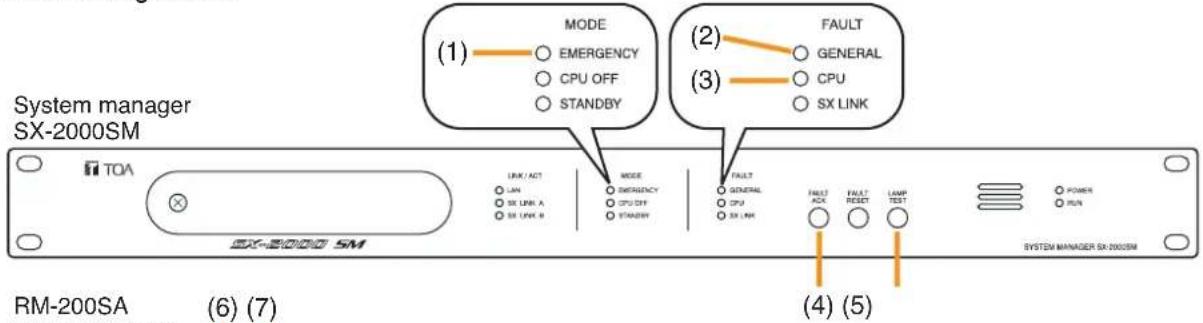
text_image
System manager SX-2000SM TOA LINK/ACT LAN SW LINK A SW LINK B MODE EMERGENCY CPU OFF STANDBY MODE EMERGENCY CPU OFF STANDBY FAULT GENERAL CPU SW LINK FAULT ACK FAULT RESET LAMP TEST POWER RUN SYSTEM MANAGER SX-2000SM RM-200SA (6) (7) (4) (5)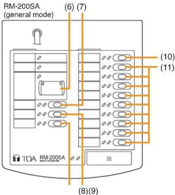
text_image
RM-200SA (general mode) (6) (7) (10) (11) TOA RM-200SA (8)(9)Figure 1: Minimum configuration for mandatory indications and controls
(1) indication of VA condition (emergency mode)
(2) general fault indication
(3) system (CPU) fault indication
(4) fault acknowledge for (2) - (3) and (7) - (9)
(5) lamp test button
(6) when the RM-200SA is set to be a general microphone, then this button cannot be programmed. Its related LED indicates the VA condition (emergency mode).
(7) power supply fault (fault receipt programming)
(8) fuse rupture (fault receipt programming)
(9) only when the system is installed in more than one location: fault in a signal path between decentralised system racks (fault receipt programming); otherwise the lamp test can be assigned to this button
(10) lamp test (if not set on (9))
(11) no function (may be used for non-emergency related functions as paging etc.)
2.3.2. Configuration with indication of faults in VA zones
In this example, the minimum requirements listed in chapter 2.1 from no. 1 to 7 are expanded by the fault indications of VA zones. The installation shall be made in a room of access level 1 and no front door of the cabinet rack shall prevent a quick access to the indication and control units. The remote microphone shall be installed adjacent to the cabinet rack containing the system manager SX-2000SM. When several cabinet racks are installed adjacent to each other and one of them containing the system manager, then the remote microphone can be installed adjacent to another cabinet rack in that group. The best place would be next to the system manager.
The remote microphone must not contain any emergency related function or a fault reset button (refer to chapter 3.1 and 3.2). When paging shall be provided, then the remote microphone must be of general type, i.e. the RM-200SA in general mode. We recommend to use the RM-200SA in general mode to avoid setting of emergency controls.
When applying the fault indication of VA zones (option with requirement, refer to item 9 of chapter 2.2), then - add surveillance on all VA related outputs
- assign each output of the same VA zone to one failure pattern, i.e. one failure pattern per VA zone
- assign each failure pattern to its own fault receipt button of the indicating remote microphone

text_image
System manager SX-2000SM TOA LINK ACT UN SX LINK A SX LINK B MODE EMBREQUENCY CPU CRT STORAGE FAULT GENERAL CPU SX LINK FAULT ACR FAULT RESET LAMP TEST POWER RUN SYSTEM MANAGER SX-2000SM RM-200SA (5) (6) (1) FAULT GENERAL CPU SX LINK (2) (3) (4)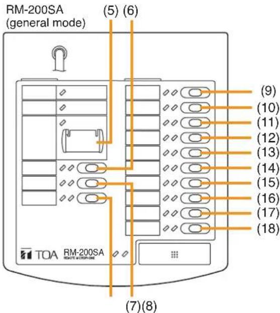
text_image
RM-200SA (general mode) (5) (6) (9) (10) (11) (12) (13) (14) (15) (16) (17) (18) TOA RM-200SA STATE MODE 04 (7)(8)Figure 2: Configuration with mandatory Indications and Indication of faults in VA Zones (explanation on next page)
(1) general fault indication
(2) system (CPU) fault indication
(3) fault acknowledge for (1) and (2)
(4) lamp test button
(5) do not program! (only emergency functions that must be in access 2 can be programmed) Its related LED indicates the VA condition.
(6) power supply fault (fault receipt programming)
(7) fuse rupture (fault receipt programming)
(8) fault in a signal path between the decentralised system racks (fault receipt programming)
(9) VA zone 1 fault
(10) VA zone 2 fault
(11) VA zone 3 fault
(12) VA zone 4 fault
(13) VA zone 5 fault
(14) VA zone 6 fault
(15) VA zone 7 fault
(16) VA zone 8 fault
(17) VA zone 9 fault
(18) lamp test
If the number of VA zones is more than 9, then further fault indications (fault receipt buttons) can be assigned on buttons of the keyboard extension RM-210 connected to the remote microphone.
3. INDICATIONS AND CONTROLS IN ACCESS LEVEL 2
Basically all alarm related manual controls and the fault reset control must be in access level 2.
3.1. Mandatory Control in Access Level 2
All faults except two ones in the SX-2000 system are reset automatically when the fault is not available anymore. The faults of amplifiers and short circuits on the speaker line require a fault reset control to re-enable the operation of them (before the reason of the fault should be removed). Therefore the fault reset button must be available but has to be in access level 2.
| No. | Indication | Preparation and requirements |
| 10 | manual fault reset | - fault reset button on system manager SX-2000SM (preparation in chapter 8, for the operation refer to the text below this table);- programming the fault reset function on a remote microphone requires to install the remote microphone in access level 2 (refer to the chapter 3.3.1 installation place);- programming the fault reset function on a control input requires to install the connected switch to be in access level 2 (e.g. in a lockable box) |
Table 3: Mandatory control in access level 2
Since the system manager SX-2000SM shall be installed in access level 1 but also containing a fault reset button, its operation was modified to meet the access level 2 requirements (refer to chapter 8 also). It is necessary to proceed a 3-step sequential procedure to make a fault reset on this button:
- push the fault reset button start for a duration between 0.1 - 1.5 seconds and release it
- push the fault reset button within 2 seconds after the previous push start for a duration between 0.1 - 1.5 seconds and release it
- push the fault reset button within 2 seconds after the previous push start for a minimum duration of 2 seconds and release it
When the pushing procedure does not cause the fault reset, then the done action was probably wrong. Then wait for 2 seconds after the last button release and start the sequence again.
3.2. Options requiring Controls in Access Level 2
All the listed functions in the next table belong to the option with requirements "VA manual control" ( §10 ).
| No. | Indication/control | Requirement and Preparation |
| 11 | Manual reset of the VA condition | Requirement: this function must be in access level 2. The manual VA reset can be assigned to a button of an emergency microphone. Please refer to the software manual for further details. If the emergency reset shall be made by an external switch, then assign this function to a control input. The connection to the switch should be monitored and the switch shall be put into access level 2. |
| 12 | Indication of the status of VA zones / zone groups | The zone status is indicated by buttons assigned for zone selection on a remote microphone. So assign the same VA zones or VA zone groups to zone selection buttons as are available for the manual controls. |
Table 4: Options requiring controls in access level 2
The options
- manual emergency activation,
- manual emergency phase shift,
- manual silencing of the voice alarm condition,
- faults of manually controlled VA zones (EN 54-16, §10.3)
must not be used because these are not certified yet. A certification is planned later.
3.3. Proposal for the Installation and Setting of an Emergency Microphone
3.3.1. Installation place
The emergency microphone (RM-200SA in emergency mode, RM-200SF) must be installed in access level 2. To do so, either install the emergency microphone in a lockable (wall-mount) box or in a room with access only by mechanical keys, access cards or entering a code of at least 3 manual sequential operations. The room or the box must be accessible only for persons having a specific responsibility for safety and who are trained and authorized to operate the emergency microphone in the voice alarm condition.
3.3.2. Settings
Depending on the requirements for the use of the emergency microphone, one or more VA zones or VA zone groups shall be set. A possibility of starting the emergency shall be provided (by emergency pattern). Fault indications (fault receipt buttons) can be set when the emergency microphone is used for paging only. Faults receipt buttons for VA zones or VA zone groups must be set if a manual control of the emergency is provided. When these fault receipt buttons are set, then these shall cover the same VA zones or VA zone groups as used for the zone selection buttons. A general fault indication might be provided also.
3.3.3. Example for a setting on an emergency microphone
1 RM-200SF and 1 RM-210
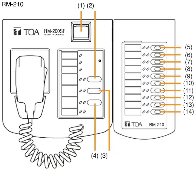
text_image
RM-210 (1) (2) TOA RM-200SF TREMONE NICKER-KNE (4) (3) (5) (6) (7) (8) (9) (10) (11) (12) (13) (14) TOA RM-210Figure 3: emergency microphone RM-200SF + RM-210 with manual VA control
(1) emergency reset
(2) general fault (fault receipt function)
(3) lamp test
(4) All-call (including all VA zones)
(5) VA zone 1 selection
(6) VA zone 1 speaker line fault receipt *
(7) VA zone 2 selection
(8) VA zone 2 speaker line fault receipt *
(9) VA zone 3 selection
(10) VA zone 3 speaker line fault receipt *
(11) VA zone 4 selection
(12) VA zone 4 speaker line fault receipt *
(13) VA zone 5 selection
(14) VA zone 5 speaker line fault receipt *
* not mandatory, can be replaced by VA zones
Further VA zones or VA zone groups can be programmed on further RM-210.
4. OVERVIEW OF THE ACCESS LEVEL REQUIREMENTS FOR THE EQUIPMENT AND RELATED FUNCTIONS
Some system components must be installed in access level 1 or 2, some can be installed in any of both. The table below gives a quick overview about that.
| Access level 2Ac | ||
| SX-2000SM | ○ | —* |
| SX-2100AI | ○ | ○ |
| SX-2000AO, SX-2100AO | ○ | ○ |
| SX-2000CI, SX-2000CO | ○ | ○ |
| VX-2000DS | ○ | — |
| Fireman microphone RM-200SF with zone selection buttons or VA control functions (and fault reset) or both (in any case) | — | ○ |
| Emergency microphone RM-200SA with zone selection buttons or VA control functions (and fault reset) or both (in any case) | — | ○ |
| General microphone RM-200SA with mandatory indications and no fault reset | ○ | — |
| General microphone RM-200SA with fault reset | — | ○ |
* Only the FAULT RESET key operation is access level 2.
Table 5: Overview of the Access Level Requirements for the Equipment and related Functions
5. POWER SUPPLY
The SX-2000 system must use the power supply system VX-2000DS ER/UK with VX-200PS ER/UK and VX-2000PF certified on EN 54-4.
The power indications must be visible in access level 1, i.e. the cabinet racks containing the VX-2000DS ER/UK must be installed in access level 1.
6. CABINETS
The cabinet racks of the CR-series, namely the CR-15, CR-22, CR-27, CR-35, CR-40 and CR-44, shall be used for installing the system components.
Each cabinet rack containing this certified SX-2000 equipment must be labelled with the label shown below. This label will be supplied as accessory with each SX-2000SM and SX-2100AO.
The same label will be provided for the remote microphones. When you install them inside a (lockable) box, put the label onto this box.
The label must be affixed so that it can be seen in access level 1.

text_image
TOA EN 54-16Figure 4: Label for cabinets
7. STANDBY (RESERVE, REDUNDANT) AMPLIFIERS
The standby amplifier's output power must be the same or more than that of the amplifier with the highest output power to be replaced in case of an amplifier fault.
8. SETTING ON THE SYSTEM MANAGER SX-2000SM
To comply with EN 54-16, set the fault reset button on the system manager SX-2000SM into the special mode.
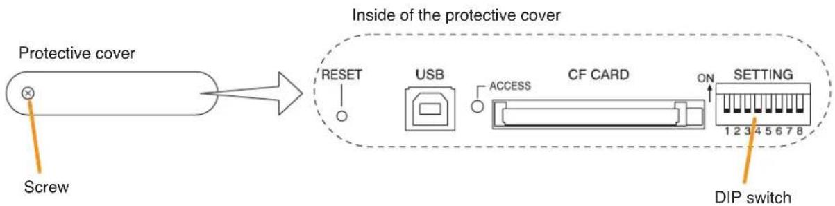
flowchart
graph LR
    A["Screw"] --> B["Protective cover"]
    B --> C["Inside of the protective cover"]
    C --> D["RESET"]
    C --> E["USB"]
    C --> F["ACCESS"]
    C --> G["CF CARD"]
    C --> H["ON"]
    C --> I["SETTING"]
    I --> J["DIP switch"]
To do so, open the protective cover, set DIP switch no. 4 to "ON."
Replace the protective cover and fix it by the screw.
For the operation of the fault reset button, please refer to chapter 3.1.