F-122CU - Speaker TOA - Free user manual and instructions
Find the device manual for free F-122CU TOA in PDF.

User questions about F-122CU TOA
0 question about this device. Answer the ones you know or ask your own.
Ask a new question about this device
Download the instructions for your Speaker in PDF format for free! Find your manual F-122CU - TOA and take your electronic device back in hand. On this page are published all the documents necessary for the use of your device. F-122CU by TOA.
USER MANUAL F-122CU TOA
natural_image
Technical line drawing of a cylindrical tank with side supports and a central base (no text or symbols)Please follow the instructions in this manual to obtain the optimum results from this unit. We also recommend that you keep this manual handy for future reference.
TABLE OF CONTENTS
- SAFETY PRECAUTIONS 3
- GENERAL DESCRIPTION ...... 3
- FEATURES 4
- NOMENCLATURE AND DIMENSIONS .... 4
- MOUNTING HARDWARE INSTALLATION .... 5
6. WIRING
6.1. Using the Speaker in UL1480 Category UUMW 9
6.2. Using the Speaker in UL1480 Category UEAY and CAN/CSA C22.2 No.205 Category UEAY7
6.2.1. Wiring through hard or flexible conduit 10
6.2.2. Wiring with naked cables 11
-
CABLE CONNECTION TO INPUT CONNECTOR 12
-
SPEAKER INSTALLATION 13
9. REMOVING THE SPEAKER FOR MAINTENANCE
9.1. Detaching the Front Grille 15
9.2. Removing the Speaker 15
-
REPAINTING THE SPEAKER 16
-
INPUT OVERLOAD PROTECTION FUNCTION 16
12. SAFETY AGENCY COMPLIANCE
12.1. Setting to the Following Positions 17
12.2. Setting to 8 Ω or 16 Ω Position .... 17
- SPECIFICATIONS ...... 18
Accessories 18
Optional Component 18
1. SAFETY PRECAUTIONS
- Be sure to read the instructions in this section carefully before use.
- Make sure to observe the instructions in this manual as the conventions of safety symbols and messages regarded as very important precautions are included.
- We also recommend you keep this instruction manual handy for future reference.
Safety Symbol and Message Conventions
Safety symbols and messages described below are used in this manual to prevent bodily injury and property damage which could result from mishandling. Before operating your product, read this manual first and understand the safety symbols and messages so you are thoroughly aware of the potential safety hazards.

WARNING
Indicates a potentially hazardous situation which, if mishandled, could result in death or serious personal injury.

CAUTION
Indicates a potentially hazardous situation which, if mishandled, could result in moderate or minor personal injury, and/or property damage.

WARNING
- Leave the installation to your TOA dealer because the installation requires expert knowledge. Improper installation may cause the unit to fall, resulting in personal injury and/or property damage.
- Install the unit in a location that can structurally support the weight of the unit and its mounting hardware. Doing otherwise may result in the unit falling down and causing personal injury and/or property damage.
- Do not use other methods than specified to mount the unit. Extreme force is applied to the unit and the unit could fall off, possibly resulting in personal injuries.
- Attach the safety wire to the unit. If not attached, the unit could fall off, resulting in personal injury.
- Tighten each screw securely. Ensure that the unit has no loose joints after installation to prevent accidents that could result in personal injury.
-
Never hold the diffuser section as a handle to carry the unit during installation. If the diffuser breaks off, the unit could fall from an elevated position, resulting in possible personal injury.
-
Use the specified mounting hardware in combination. Doing otherwise may cause the unit or component to fall off, resulting in personal injury.
-
Should the following irregularity be found during use, immediately stop operating the unit and contact your nearest TOA dealer. Further attempt to use under this condition may cause fire or electric shock.
-
If you detect smoke or a strange smell coming from the unit
- If no tone sounds

CAUTION
- Avoid installing the unit in humid or dusty locations, in locations exposed to the direct sunlight, near the heaters, or in locations generating sooty smoke or steam as doing otherwise may result in fire or electric shock.
- Do not operate the unit for an extended period of time with the sound distorting. This is an indication of a malfunction, which in turn can cause heat to generate and result in a fire.
2. GENERAL DESCRIPTION
The F-122CU is a flush-mounted ceiling speaker that offers a wide frequency range of high-quality sound output. Use of its supplied mounting hardware and optional HY-TB1 Tile Bar Bridge permits it to be versatilely mounted to match a wide range of applications and installation locations.
3. FEATURES
- Bass-reflex speaker system designed to provide a wide frequency range and high power handling capability.
- Wide-dispersion flush-mount ceiling speaker design employs unique acoustic construction to realize a wide area of coverage. Uniform sound output levels are achievable not only directly under the speaker, but also over a wide radius.
- Because the speaker is provided with both low- and high-impedance operating capability, it can be used in many different applications. Front panel-mounted input selector switch permits easy verification and change of current impedance settings.
- Easy installation. Can be quickly and accurately mounted to ceilings.
- Rotating front grille can be installed quickly and conveniently.
- Attractive exterior design specially created by an interior designer blends naturally with any architectural space, enhancing the immediate area's sense of harmony.
4. NOMENCLATURE AND DIMENSIONS
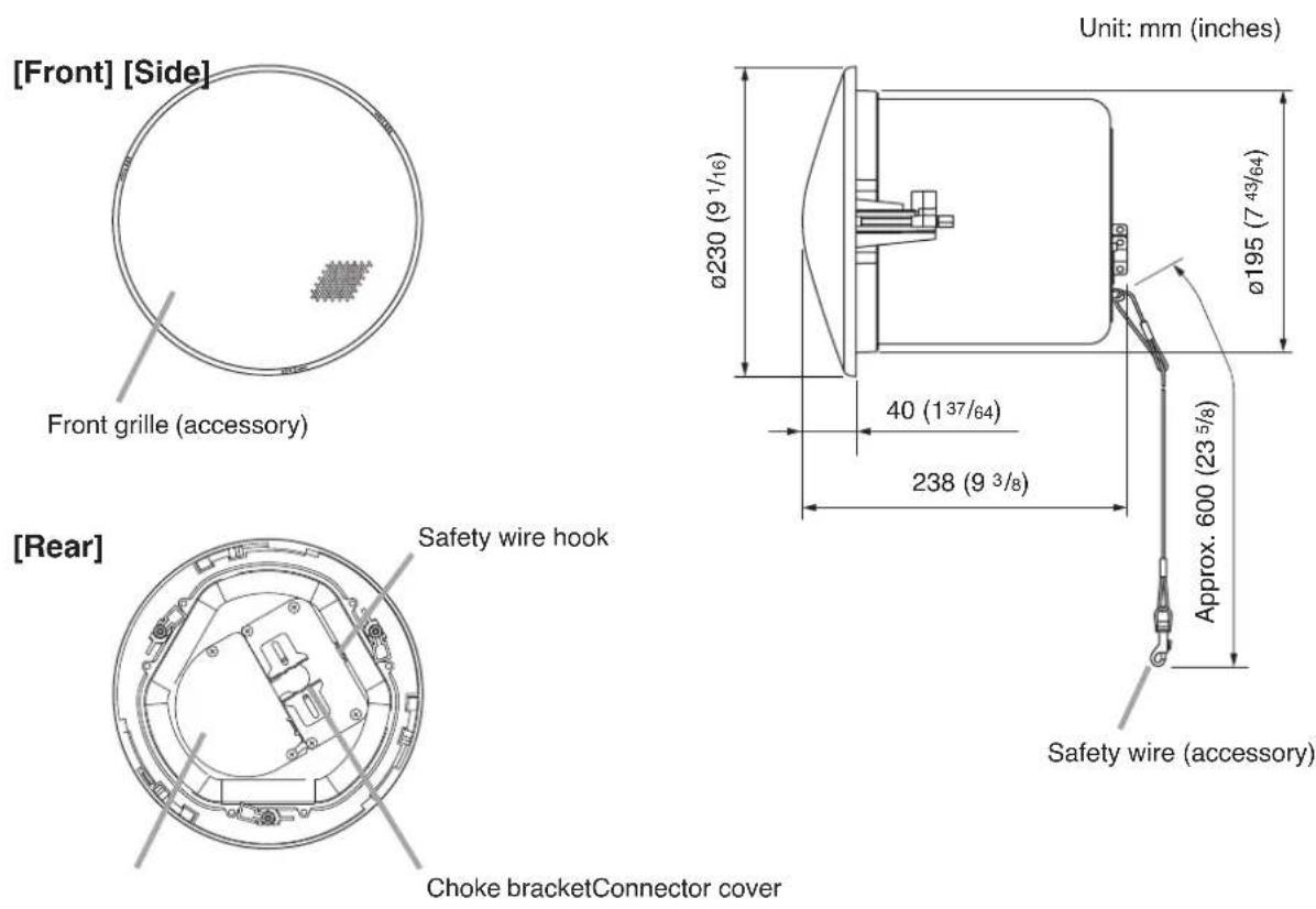
[Ceiling mounting]

text_image
Mounting mounting] Mounting hole: Ø200 (7 7/8) Ceiling reinforcement ring (accessory) Max. 37 (1 29/64) Max. 202 (7 61/64) Ceiling panel5. MOUNTING HARDWARE INSTALLATION
Before mounting the speaker, determine the most appropriate method for the existing ceiling structure. Be sure to use an optional HY-TB1 Tile Bar Bridge in combination with the supplied ceiling reinforcement ring.
[Installation view on Drop Ceilings]
Because the bridge rails are 603 mm (23 ^47/64 ) in length, be sure to match them to the ceiling tile size during installation.
Caution
Set the bridge rails so that both ends fit securely into the T-grids, even if the ceiling tile accidentally falls off.
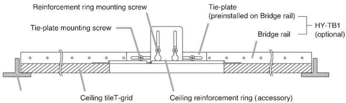
text_image
Reinforcement ring mounting screw Tie-plate mounting screw Tie-plate (preinstalled on Bridge rail) Bridge rail HY-TB1 (optional) Ceiling tileT-grid Ceiling reinforcement ring (accessory)[Installation view on Dry Wall Ceilings]
Caution
Only install the Tile Bar Bridge on ceiling frames that can structurally support the weight of the speaker(s).
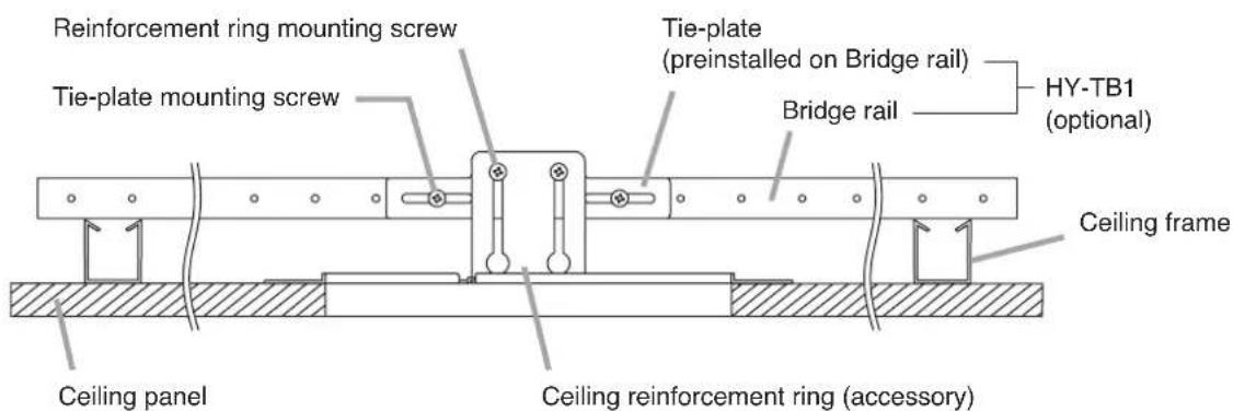
text_image
Reinforcement ring mounting screw Tie-plate mounting screw Tie-plate (preinstalled on Bridge rail) Bridge rail HY-TB1 (optional) Ceiling frame Ceiling panel Ceiling reinforcement ring (accessory)Step 1. Cut a 200 mm (7 ^7/8 ") hole in the ceiling.
Use the supplied paper pattern to position and trace the hole.
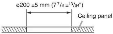
text_image
ø200 ±5 mm (7^7/8 ±13/64") Ceiling panelStep 2. Install the HY-TB1 in the ceiling.
Loosen the two reinforcement ring mounting screws in each tie-plate to the point that they do not fall out of their holes.

text_image
HY-TB1 (optional) Tie-plate Bridge rail Tie-plate mounting screwReinforcement ring mounting screws (Leave these screws loose.)
[For Drop Ceiling]
- Mounting to 2-foot tiles
Align the two bridge rails as shown in the figure at right.
![TOA F-122CU - [For Drop Ceiling] - 1](/content/2026/06/1214021/images/0913d7de8fe3dda15d1baf7860212097ff1e3bf9b7acd01cc78a1cd1f07304fe.jpg)
text_image
2-foot tile HY-TB1 (optional) T-grid- Mounting to 600 mm tiles
Align the two bridge rails diagonally at an angle of 10^-15^ .
![TOA F-122CU - [For Drop Ceiling] - 2](/content/2026/06/1214021/images/7b0598f4d90a88859df333e83a878b62eebe884957773bb4d7728d7db3a0274f.jpg)
text_image
600 mm tile HY-TB1 (optional) 10° - 15° T-gridStep 3. Place the supplied reinforcement ring on the ceiling panel.
Fold the reinforcement ring in half* and insert it through the mounting hole in the ceiling panel, then open it with its tabs facing up.
Place the ring on the ceiling panel aligning it with the mounting hole.
* The reinforcement ring is too large to be inserted into the mounting hole unless folded.
![TOA F-122CU - [For Drop Ceiling] - 3](/content/2026/06/1214021/images/273e329933973207ace8a455bbeafa4a6d003b6e3d39d07d7da428b02d620112.jpg)
text_image
Mounting hole Ceiling reinforcement ring (accessory)Reinforcement ring placed on the ceiling panel
![TOA F-122CU - [For Drop Ceiling] - 4](/content/2026/06/1214021/images/04e4a25a51dba602e93a90c6615d60bba7ac3252287b654e23a09615235587b4.jpg)
natural_image
Technical line drawing of a circular mechanical component with two mounting brackets and a central hub (no text or symbols)These tabs must face upward, away from the hole.
Step 4. Attach the ceiling reinforcement ring to each tie-plate using 2 reinforcement ring mounting screws.
![TOA F-122CU - [For Drop Ceiling] - 5](/content/2026/06/1214021/images/2cf35aa5741f448b166da742463951c7bd0a2cb6e989f5c0c8a3a61a12d1e895.jpg)
text_image
Reinforcement ring mounting screw 1 Tie-plate Ceiling reinforcement ring 2 Fit closely to the back surface of the ceiling panel.If the ceiling reinforcement ring does not line up accurately with the ceiling mounting hole, adjust its position by either loosening the tie-plate mounting screws and sliding the tie-plate into correct position, or by shifting the tie-plate mounting screws to the appropriate holes in the Tile Bridge rails.
The ceiling reinforcement ring can be moved in the direction indicated by the arrows.
Note
Be sure to tighten the tie-plate mounting screws after completing the adjustment.
Tie-plate mounting screw
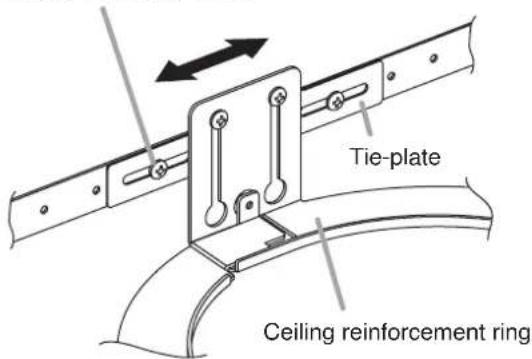
text_image
Tie-plate Ceiling reinforcement ringStep 5. Attach a safety wire to prevent the speaker from accidentally falling.
To attach, tie one end of the supplied safety wire around the speaker's safety wire hook, and tie its snap ring around the installed HY-TB1 or a solid structure.
Note
When there is no gap between the bridge rails and the ceiling panel, to secure the safety wire, tie the wire around a solid structure (pipe, building frame, etc.).
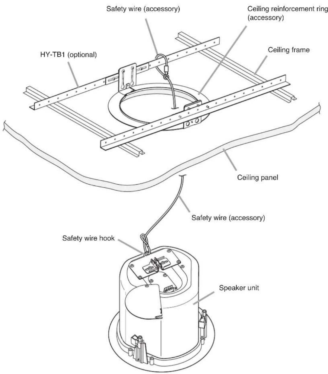
text_image
Safety wire (accessory) HY-TB1 (optional) Ceiling reinforcement ring (accessory) Ceiling frame Ceiling panel Safety wire (accessory) Safety wire hook Speaker unit6. WIRING
6.1. Using the Speaker in UL1480 Category UUMW
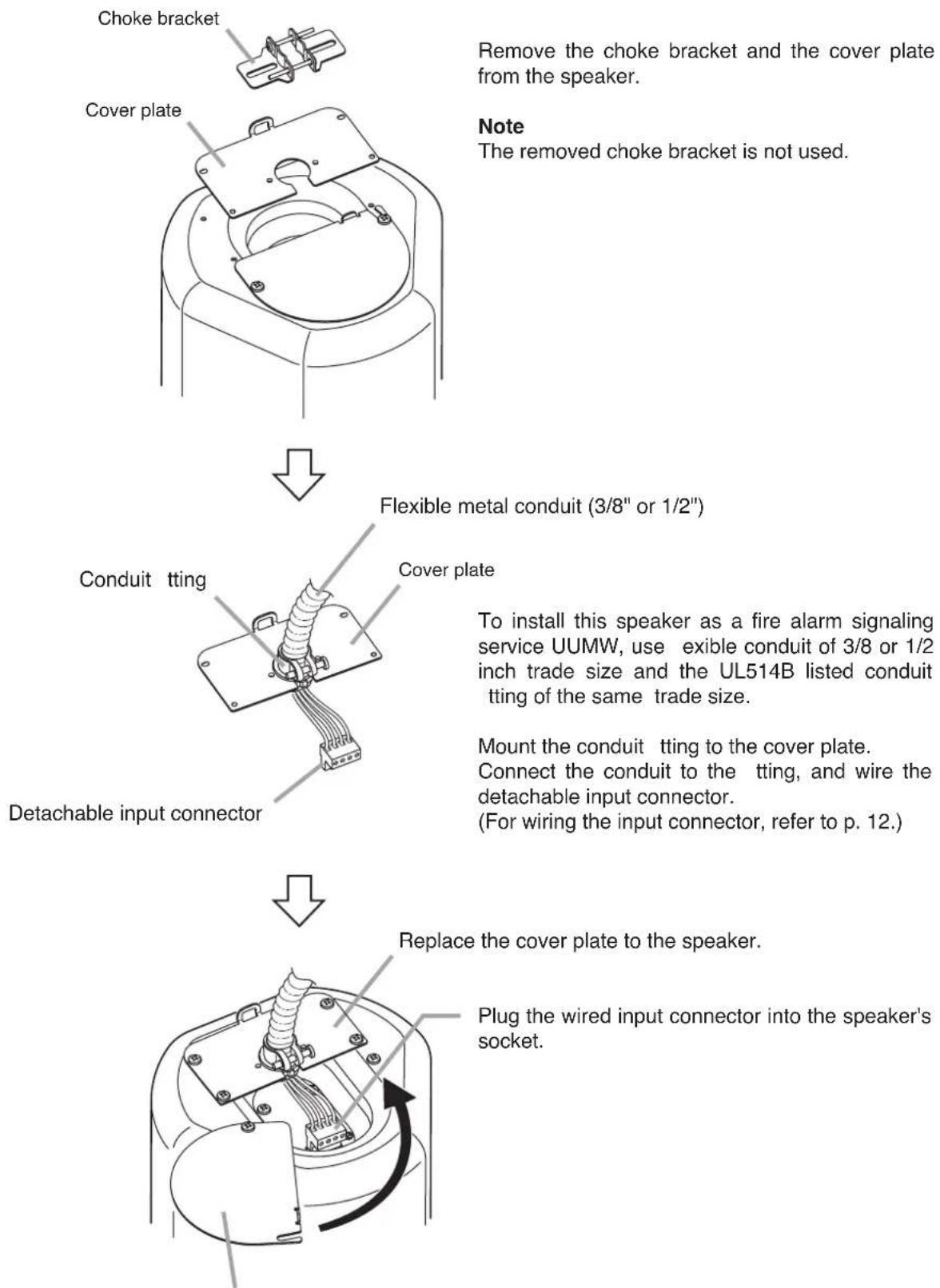
flowchart
graph TD
    A["Choke bracket"] --> B["Cover plate"]
    B --> C["Flexible metal conduit (3/8" or 1/2")"]
    C --> D["Conduit tting"]
    D --> E["Cover plate"]
    E --> F["To install this speaker as a fire alarm signaling service UUMW, use exible conduit of 3/8 or 1/2 inch trade size and the UL514B listed conduit tting of the same trade size."]
    F --> G["Mount the conduit tting to the cover plate. Connect the conduit to the tting, and wire the detachable input connector. (For wiring the input connector, refer to p. 12.)"]
    G --> H["Replace the cover plate to the speaker."]
    H --> I["Plug the wired input connector into the speaker's socket."]
Connector cover
After completing the speaker cable connection, turn the connector cover in the direction indicated by the arrow, and fix the cover with 2 screws.
6.2. Using the Speaker in UL1480 Category UEAY and CAN/CSA C22.2 No.205 Category UEAY7
6.2.1. Wiring through hard or flexible conduit
Note
The choke bracket equipped with the speaker has not been evaluated by UL, for conduit connection and UL514B Standard.
Flexible conduit of 3/8 or 1/2 inch trade size and the UL514B conduit fitting of the same trade size can also be used. For the method of conduit connection, refer to p. 9.
Loosen the screw to allow the speaker cable to pass through.
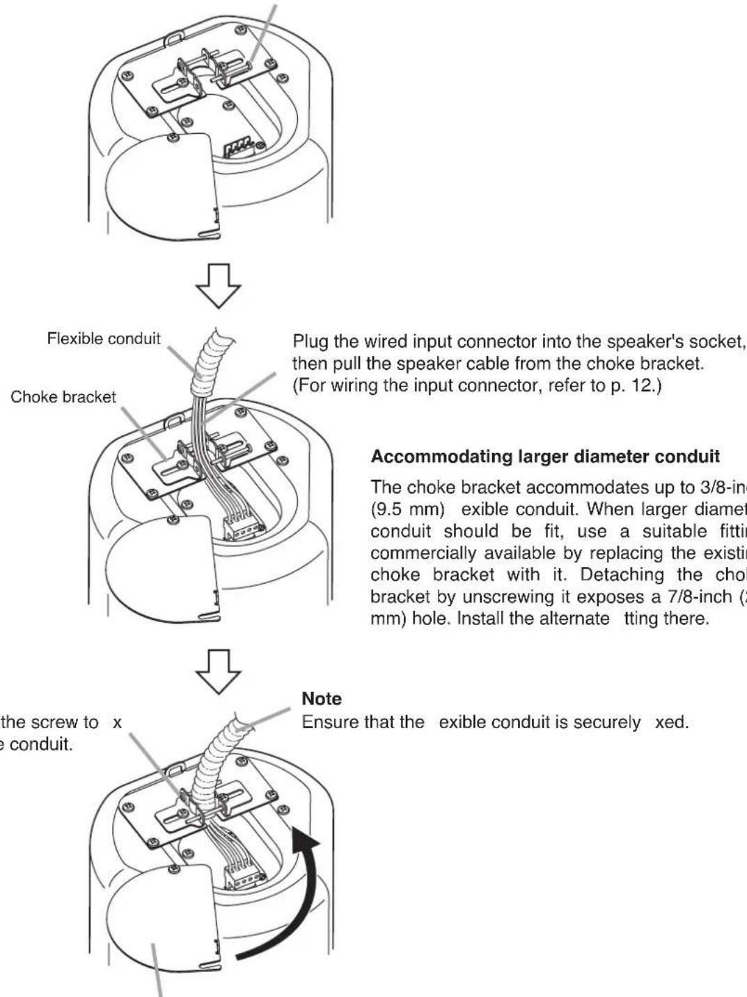
flowchart
graph TD
    A["Choke Bracket"] --> B["Flexible Conduit"]
    B --> C["Plug the wired input connector into the speaker's socket, then pull the speaker cable from the choke bracket. (For wiring the input connector, refer to p. 12.)"]
    C --> D["Accommodating larger diameter conduit"]
    D --> E["The choke bracket accommodates up to 3/8-inch (9.5 mm) exible conduit. When larger diameter conduit should be fit, use a suitable fitting commercially available by replacing the existing choke bracket with it. Detaching the choke bracket by unscrewing it exposes a 7/8-inch (2 mm) hole. Install the alternate tting there."]
    E --> F["Note: Ensure that the exible conduit is securely xed."]
Connector cover
After completing the speaker cable connection, turn the connector cover in the direction indicated by the arrow, and fix the cover with 2 screws.
6.2.2. Wiring with naked cables
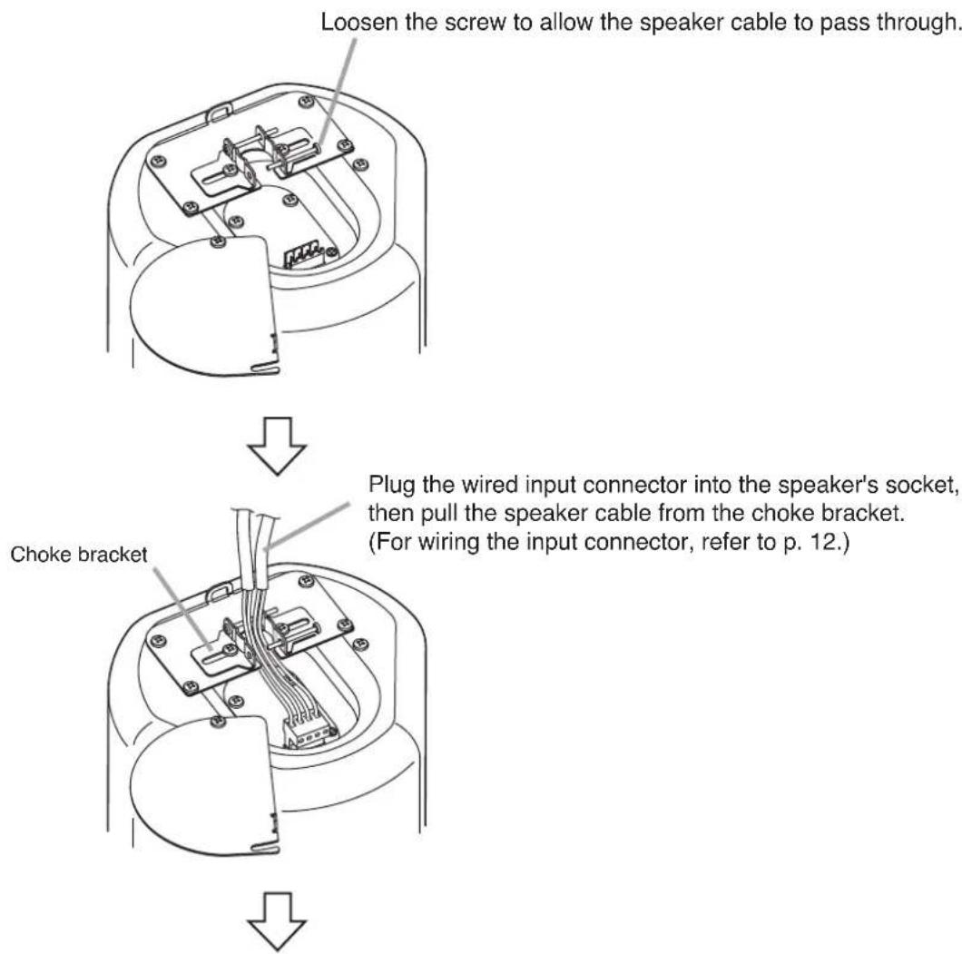
text_image
Loosen the screw to allow the speaker cable to pass through. Choke bracket Plug the wired input connector into the speaker's socket, then pull the speaker cable from the choke bracket. (For wiring the input connector, refer to p. 12.)Retighten the screw to x the speaker cable.
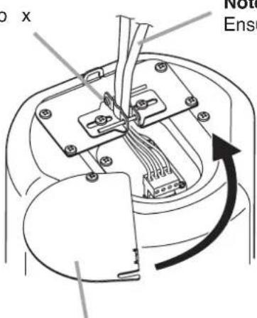
text_image
O x Note EnseNote
Ensure that the speaker cable is securely xed.
Connector cover
After completing the speaker cable connection, turn the connector cover in the direction indicated by the arrow, and fix the cover with 2 screws.
7. CABLE CONNECTION TO INPUT CONNECTOR
Recommended cable types
• Solid copper wire: 1.0-1.6 mm
(equivalent to AWG 18 - 14)
- Stranded copper wire: 0.75 - 2.5 ~mm^2
(equivalent to AWG 18 - 14)
Step 1. Loosen the 2 cover mounting screws, and rotate the connector cover in the direction indicated by the arrow in the figure at right.
Cover mounting screw
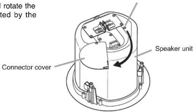
text_image
I rotate the tied by the Connector cover Speaker unitStep 2. Remove the detachable input connector from the speaker's socket, and loosen the screw of the terminal to be used.
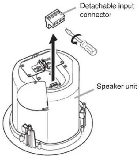
text_image
Detachable input connector Speaker unitStep 3. Insert the stripped cable end into the terminal and tighten the terminal screw with a screwdriver.
[If bridging][If not bridging]
Caution
If not making bridge connections, be sure to tighten unused terminal screws to avoid their vibration.

text_image
ions, minal . 5 mm (13/64")From Ampli er
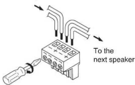
text_image
To the next speaker8. SPEAKER INSTALLATION
Caution
Before mounting, check to be sure that the speaker's 3 mounting tabs are turned inside the unit as shown in the figure.
If turned outward, the speaker cannot be inserted through the mounting hole.
Mounting tab
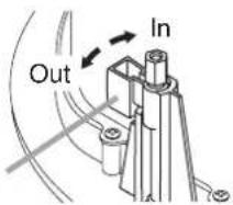
text_image
Out InStep 1. Insert the speaker through the mounting hole till it contacts the ceiling panel. While doing so, avoid directly touching the speaker's diffuser section.

WARNING
Never hold the diffuser section as a handle to carry the speaker during installation. If the diffuser breaks off, the unit could fall from an elevated position, resulting in possible personal injury.

text_image
Diffuser section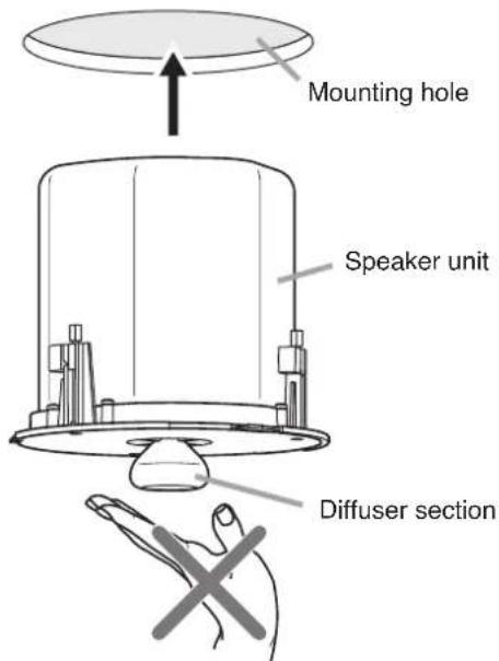
text_image
Mounting hole Speaker unit Diffuser sectionStep 2. Rotate and tighten the mounting tab axis screws (3 places) on the unit clockwise to their full stop in order to grip the ceiling panel with the mounting tabs.
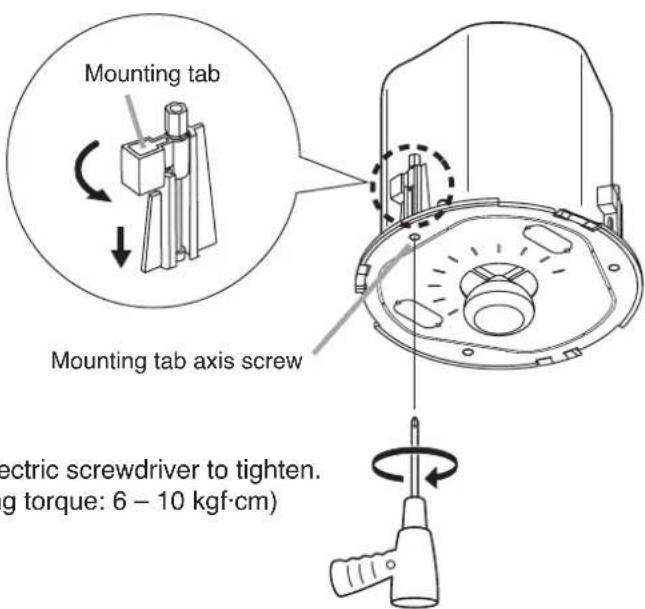
text_image
Mounting tab Mounting tab axis screw electric screwdriver to tighten. (ng torque: 6 - 10 kgf·cm)Use an electric screwdriver to tighten. (Tightening torque: 6 - 10 kgf·cm)
Step 3. Set the input power.
Turn the input selector switch (on the unit's front) to set it to the desired input impedance.
(Factory-preset to 170 Ω.)
Note
Setting positions "8 Ω" and "16 Ω" can be used in UL1480 Category UEAY and CAN/CSA C22.2 No.205 Category UEAY7.
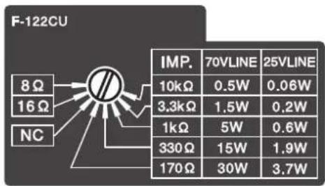
text_image
F-122CU 8 Ω 16 Ω NC IMP. 70VLINE 25VLINE 10kΩ 0.5W 0.06W 3.3kΩ 1.5W 0.2W 1kΩ 5W 0.6W 330 Ω 15W 1.9W 170 Ω 30W 3.7WStep 4. Attach the front grille.
Align the tabs (3 places) on the back side of the grille with the corresponding notches in the unit, then rotate the grille to full stop in the direction indicated by the "LOCK" arrow.
Tip
The front grille employs a double-locking system that clicks into place once partway through rotation, but only locks into position at its point of full rotation. Always be sure to rotate the grille to its full stop.
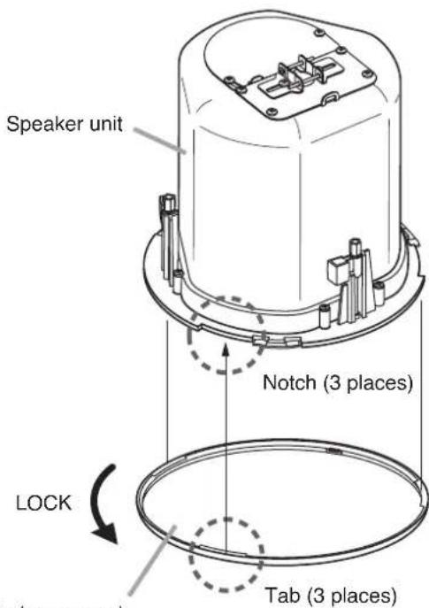
text_image
Speaker unit Notch (3 places) LOCK Tab (3 places)Front grille (accessory)
9. REMOVING THE SPEAKER FOR MAINTENANCE
9.1. Detaching the Front Grille
Turn the front grille counterclockwise to full stop, then lightly pull it downward.
Tip
The front grille employs a double-locking system.
If the grille cannot be detached when lightly pulled downward, it likely has not yet been fully rotated back to the detachment position. In such cases, take care to rotate the grill fully counterclockwise in order to release the lock.
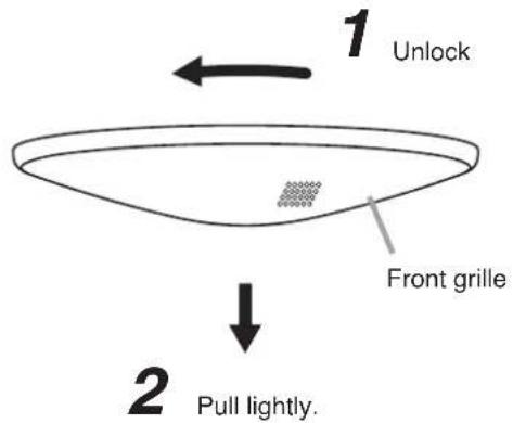
text_image
1 Unlock Front grille 2 Pull lightly.9.2. Removing the Speaker
Rotate the 3 mounting tab axis screws counterclockwise. The mounting tabs rise as they turn, allowing the speaker to be removed.
Caution
When loosening the mounting tab axis screws, support the speaker by hand to prevent it from falling.
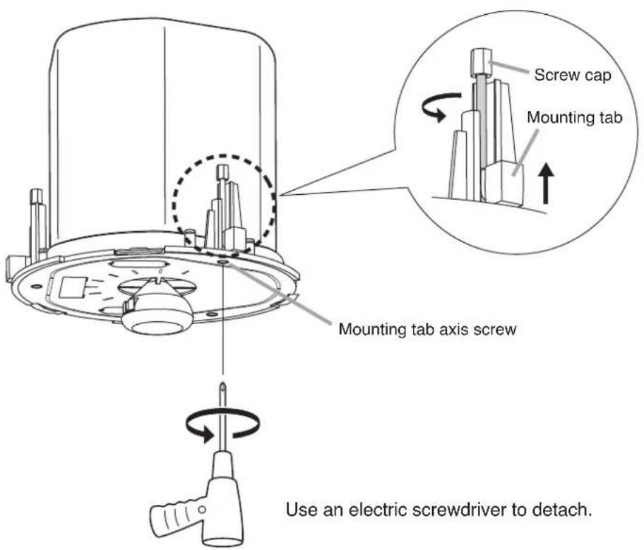
text_image
Screw cap Mounting tab Mounting tab axis screw Use an electric screwdriver to detach.Caution
Be sure to set the screwdriver's torque for under 4 kgf·cm.
Failure to do so may cause the Screw cap and the Mounting tab to fall off on the rear of ceiling panel.
10. REPAINTING THE SPEAKER
Follow the procedure below when repainting the front grille:
Step 1. Clean the front grille before painting.
Wipe with a soft cloth dampened in a detergent.
Caution
Do not use thinner or other volatile liquids to clean the grille.
Step 2. Spray on a uniform, thin coat of paint.
Cautions
- Avoid painting with a roller or brush, as the grille mesh holes could become clogged with paint.
- Use appropriate spray paints for the front grille (grille and frame) materials.
Grille: Rolled steel plate
Frame: Fire-resistant ABS resin (acrylic paint) - Be sure to follow the directions indicated on the paint when painting.
Step 3. After the paint has dried, apply another light coat.
Caution
Repeating Step 2, apply two or more light coats of paint.
Application of one thick coat of paint all at once may cause drips or unevenness to show up in the painted finish, or clog the mesh holes.
11. INPUT OVERLOAD PROTECTION FUNCTION
The F-122CU features an internal input overload protection circuitry. If an extremely high input level is fed to the unit, the protection circuitry automatically cuts off the signal to the speaker element.
A drastic reduction in sound volume indicates that the protection circuitry has been enabled.
In such cases, simply reduce the amplifier volume. The protection circuitry will automatically reset in approximately 10 seconds. After reset, try to maintain the volume at a level slightly lower than before.
Caution
This protection circuitry does not completely protect the unit against extremely high input power levels. Depending on the type or duration of excessive power input, the protection circuitry might not be enabled, resulting in damage to the speaker element. Also, if the excessive power input continues for a long period of time, the circuitry may not be capable of resetting to its original condition.
Use the system with care so that the speakers are not exposed to excessive power input.
12. SAFETY AGENCY COMPLIANCE
This product is for indoor use only.
SIGNALING

FIRE ALARM EQUIPMENT 16VP
LISTED

US LISTED
16VP GENERAL SIGNALING EQUIPMENT
The F-122CU's front-mounted rotary switch permits selection of speaker handling power (wattage) on 25 V or 70 V line operation or low impedance (8 Ω or 16 Ω) operation.
Depending on the switch settings, the unit complies with the different UL Categories as follows.
Note: Setting to the "8 Ω" and "16 Ω" positions allows the unit to comply with Category UEAY/UEAY7.
12.1. Setting to the Following Positions
| 70 V Line 25 V Line | ||||||||||||
| Setting Position | 0.5 W | 1 | 5 W | 5 W | 15 W | 30 W | 0.06 W | 0.2 W | 0.6 W | 1.9 W | 3.7 W | |
[Fire protective signaling speaker, UL1480 Category UUMW]
Products Listed under this category are suitable for use in the following configurations:
a. For fire alarm signaling service in conjunction with Listed compatible emergency communication and relocation equipment and/or fire alarm control unit, the combination of which is intended to be installed in accordance with the applicable requirements of NFPA 72, the National Electrical Code (NEC) and the local authority having jurisdiction.
b. For general (non-fire alarm) signaling service in conjunction with compatible Listed audio equipment, the combination of which is intended to be installed in accordance with the applicable requirements of the National Electrical Code (NEC) and the local authority having jurisdiction.
[Suitable for use in air-handling spaces (UL2043)]
Fire Test for Heat and Visible Smoke Release for Discrete Products and their Accessories Installed in Air-Handling Spaces (1998) - NFPA 70 National Electrical Code (NEC) 2002, Article 300-22 (c) and NFPA 90A Installation of air-conditioning and ventilation systems, section 2-3.10.1 (a) exception 3.
[Sound Pressure Level (SPL) specs]
Loudspeaker sound pressure level is measured per UL1480/ANSI-S1.12/ANSI-S1.2 in the specified reverberant chamber.
| 70 V Line 25 V Line | |||||||||||
| Setting Position | 0.5 W 1 | 5 W 5 W | 15 W | 30 W | 0.06 W | 0.2 W | 0.6 W 1.9 | W 3.7 W | |||
| dB at 10 feet 74 | dB 78 dB | 83 dB 87 | dB 90 | dB 65 dB | 70 dB 75 | dB 79 | dB 82 dB | ||||
12.2. Setting to 8 Ω or 16 Ω Position
[General signaling speaker, UL1480 Category UEAY and CAN/CSA C22.2 No.205 Category UEAY7]
Products Listed under this category are suitable for use in general (non-fire alarm) signaling service in conjunction with compatible Listed audio equipment, the combination of which is intended to be installed in accordance with the applicable requirements of the National Electrical Code (NEC) and the local authority having jurisdiction.
[Suitable for use in air-handling spaces (UL2043)]
Fire Test for Heat and Visible Smoke Release for Discrete Products and their Accessories Installed in Air-Handling Spaces (1998) - NFPA 70 National Electrical Code (NEC) 2002, Article 300-22 (c) and NFPA 90A Installation of air-conditioning and ventilation systems, section 2-3.10.1 (a) exception 3.
13. SPECIFICATIONS
| Enclosure Bass reflex type | |
| Rated Input 30 W (High Impedance) | |
| Power Handling Capacity | Continuous pink noise: 60 W (8 Ω), 30 W (16 Ω) |
| Impedance | 70 V line: 170 Ω (30 W), 330 Ω (15 W), 1 kΩ (5 W), 3.3 kΩ (1.5 W), 10 kΩ (0.5 W)25 V line: 170 Ω (3.7 W), 330 Ω (1.9 W), 1 kΩ (0.6 W), 3.3 kΩ (0.2 W), 10 kΩ (0.06 W)16 Ω, 8 Ω |
| Frequency Response 70 – | 20,000 Hz |
| Speaker Component 12 cm (5") cone-type | |
| UL Code UL1480 (UUMW/UEAY), UL2043, CAN/CSA C22.2 No.205 (UEAY7) | |
| Mounting Hole ø200 mm (77/8")Maximum ceiling thickness: 37 mm (129/64") | |
| Input Terminal | Removable locking connector with screw-down terminals(2 input terminals and 2 bridge terminals) |
| Usable Cable | Solid copper wire: ø1.0 – ø1.6 mm (Equivalent to AWG 18 – 14)Stranded copper wire: 0.75 – 2.5 mm2 (Equivalent to AWG 18 – 14) |
| Finish | Enclosure: Steel plate, platingBaffle: Fire-resistant ABS resin (resin material grade: UL-94 V-0 or its equivalent), blackRim: Fire-resistant ABS resin (resin material grade: UL-94 V-0 or its equivalent), white, paintPunching net: Steel plate, white, paint |
| Dimensions ø230 mm (91/16") x Depth 238 mm (93/8") | |
| Weight | 3.8 kg (including mounting accessories) |
Note: The design and specifications are subject to change without notice for improvement.
- Accessories
Front grille .... 1
Ceiling reinforcement ring 1
Safety wire (approx. 60 cm or 23 ^5/8 ) ...... 1
Paper pattern 1
- Optional Component
HY-TB1 (Tile Bar Bridge): Use this bridge when mounting the speaker unit to drop ceiling or weak dry wall ceiling.