
VT-IPSN16M - Network video recorder Vitek - Free user manual and instructions
Find the device manual for free VT-IPSN16M Vitek in PDF.


| Product type | Network Video Recorder (16 channels) |
| Supported cameras | Up to 16 IP cameras (including Vitek, Axis, Panasonic, Mobotix, Arecont Vision, IQinvision, Vivotek) |
| Video compression | H.264, MPEG-4, MJPEG |
| Max recording resolution | Up to 16 MP (7.5 fps per channel), 8 MP (15 fps), 4 MP (real-time) |
| Recording performance | 120 fps (NTSC) / 100 fps (PAL) in duplex or triplex mode with all channels at HD |
| Hard drive support | Up to 2 TB SATA HDD (supports one internal drive) |
| Network interface | 1x Gigabit Ethernet (10/100/1000 Base-T) |
| Serial interface | 1x RS-232 (COM port, max 115200 bps) |
| Audio | Two-way audio recording and transmission |
| Motion detection | Built-in motion detection with configurable sensitivity and zones |
| PTZ control | Supported via web browser and EN-V-R software |
| Web browser management | Full configuration and live view via Internet Explorer |
| Power supply | DC 12V, 5A (external adapter) |
| Power consumption | Max 1.8A (21.6W), typical 1.0A (12W) with 1TB HDD |
| Dimensions (W x D x H) | 224 x 140 x 44 mm (8.82 x 5.51 x 1.73 inches) |
| Weight (without HDD/power supply) | 0.95 kg (2.09 lbs) |
| Operating temperature | 0°C to 50°C (32°F to 122°F) |
| Humidity | 20% to 80% RH (non-condensing) |
| Certifications | FCC Class A, CE Class A, RoHS |
| Warranty | 3 years limited (excluding hard drive) |
| Included accessories | Power adapter, CD-ROM with manual and software, quick start guide |
Frequently Asked Questions - VT-IPSN16M Vitek
User questions about VT-IPSN16M Vitek
0 question about this device. Answer the ones you know or ask your own.
Ask a new question about this device
Download the instructions for your Network video recorder in PDF format for free! Find your manual VT-IPSN16M - Vitek and take your electronic device back in hand. On this page are published all the documents necessary for the use of your device. VT-IPSN16M by Vitek.
USER MANUAL VT-IPSN16M Vitek
• Supports up to 16 IP Cameras
• Supports 4 Mega pixel cameras at real-time / 8 Mega pixel at 15fps/each / 16 Mega pixel cameras 7.5fps/each
• Audio recording & transmission
- Configuration and control through Web browsers
• Supports Hard Drives up to 2TB SATA
- Multi-Vendor camera support
- H.264 Compression
- RS-232 Serial port
- Gigabit Ethernet
• Built-in motion detection
- PTZ control
Table of Contents
1. Product Overview ......6
1.1. VT-IPSN16M 6
1.2. Key Features....6
1.3. Specifications....7
1.4. VT-IPSN16M Packing List 8
2. Hardware description....9
2.1. VT-IPSN16M Front View 9
2.2. VT-IPSN16M Rear View 10
2.2.1. COM Port Description....11
3. VT-IPSN16M Installation and Basic Setup....12
3.1. Before Installation....12
3.2. Factory Default Settings....12
3.3. Installing VT-IPSN16M....12
4. Software Installation....13
5. IP Installer: Introduction....16
6. Installing and Uninstalling....16
6.1. Installing IP Installer 16
6.2. Uninstalling IP Installer....19
7. Using IP Installer....22
7.1. Starting the Program....22
7.2. Search Product....23
7.3. Manual Network Setup 24
7.4. Automatic Network Setup 26
7.5. Using DHCP Server 29
7.6. Using PPPoE 29
7.7. Updating Firmware 31
7.8. Filter Configuration....33
7.9. Live View 34
8. ENVI Admin Menu 36
8.1. Entering Admin Menu 36
8.2. Admin Menu Structure 37
9. Quick Configuration 37
9.1. Step 1: Changing Server Name ....37
9.2. Step 2: Time Setup ....37
9.3. Step 3: Network Setup .... 37
9.4. Step 4: IPCCTVDNS.COM....38
9.5. Step 5: Recording Configuration....38
9.6. Finish 38
10. System Configuration Menu 38
10.1. Server Name Setup....38
10.2. Date & Time....39
10.3. Admin Password....40
10.4. Access Control....40
10.5.User Registration 40
10.5.1. Add....40
10.5.2. Edit 42
10.5.3. Delete 42
11. Network Configuration....42
11.1. Static IP Configuration 43
11.2. DHCP Client Configuration....43
11.3. PPPoE Configuration 44
11.4. Network Ports 44
11.5. Bandwidth Control Configuration 45
11.6.View Network Status....45
11.7. Network Status Notify....46
11.8. IP-CCTV DNS Setup 47
11.9. Port Forwarding & UPnP 48
11.10.RTP/RTSP Setup....49
12. Device Configuration ....51
12.1. Privacy Zone 51
12.2. Camera & Motion 53
12.2.1. Camera Configuration....55
13. Advanced Configuration....59
13.1. Advanced Services....60
13.1.1. E-mail Service Configuration....61
13.1.2. FTP (Buffered) Service Configuration....64
13.1.3. FTP (Periodic) Service Configuration....66
14. Recording Configuration for Cameras with microSD card 68
14.1. MicroSD Configuration 68
14.2. Recording Configuration with microSD card....71
15. Utilities....74
15.1. System Log....75
15.2. Save Configuration 75
15.3. Reboot....75
15.4. Factory Default....76
15.5. System Update....76
- ENVI Series Viewer....79
16.1. Introduction....79
16.2. Key Features....79
16.3. System Requirement for PC....79
- Installing and Uninstalling....80
17.1. Installing ENVI Series Viewer 80
17.1.1. Installing on Web Browser....80
17.1.2. Manual Installation....82
17.2. Uninstalling ENVI Series Viewer 83
17.2.1. Uninstalling with Program Menu....83
17.2.2. Uninstalling on Control Panel 84
- Starting ENVI Series Viewer 85
18.1. Control Bar 86
18.2. Channel Control Bar....87
18.3. OSD Channels Buttons....87
18.3.1. Saving as Image File 87
18.3.2. Saving as Video File 88
18.3.3. Manual Recording 88
18.3.4. Instant Playback 89
18.4. Extended Features....90
18.4.1. Pausing Live Video 90
18.4.2. FPS Control 90
18.4.3. Flip Control....91
- EN-V-R: Introduction....92
- Requirements for Installation....93
20.1. EN-V-R Versions....93
20.2. System Requirement for PC....93
- Installing EN-V-R....94
- Uninstalling EN-V-R 96
22.1. Closing Active EN-V-R....96
22.2. Executing Uninstaller 97
- Components of EN-V-R Program 98
23.1. EN-V-R Configurator 98
23.2. EN-V-R Service....98
23.3. EN-V-R Controller 98
23.4. EN-V-R System Tray Menu 99
- Starting EN-V-R Configurator 99
- Quick Start Guide 101
25.1. EN-V-R Configurator User Interface 101
25.2. Searching for IP Devices 102
25.3. Registering IP Devices 103
25.4. Viewing Live Video 106
25.5. Recording Video 107
- ENVI Smart Player....112
26.1. Introduction....112
26.2. Key Features....112
26.3. System Requirement for PC....112
- Installing and Uninstalling.... 113
27.1. Installing Smart Player.... 113
27.1.1. Manual Installation.... 113
27.2. Uninstalling Smart Player 115
27.2.1. Uninstalling on Program Menu 115
- Configuring & Viewing Player 125
28.1.Main Window View 126
28.2. Connecting to NVR Player 127
28.3. Creating a Group 127
- Searching Video 129
29.1. Searching Video 129
29.2. Daily Search....129
29.2.1. Search Mode.... 130
29.2.2. GO to Time Position 130
29.3. Condition Search Mode 130
29.3.1. Advanced Search Mode 131
- Video Playback Controls....132
- Extra Features 133
31.1. Window Control.... 133
31.2. Recording Period 133
31.3. Backup 134
31.4. Snapshot 135
31.5. Print 136
31.6. Ratio Display 136
- EN-V-R Configuration 138
32.1. System, Network Configuration 138
32.1.1. Configuring System name.... 138
32.1.2. System, Network Configuration - Admin password 139
32.1.3. System, Network Configuration - Access Control 139
32.1.4. System, Network Configuration - HTTP Port.... 140
32.1.5. System, Network Configuration—IP CCTV-DNS 140
-
IP-CCTV DNS Registration 141
-
IP-Device Registration 147
34.1. IP-Device Registration (Manual) 147
34.2. IP-Device Registration (Automatic) 149
IP-Device Modification....151
34.3. IP-DeviceDeletion....153
34.4. IP-Device Homepage 153
34.5. Camera Management....153
34.5.1. Configure Camera Name and Information.... 154
34.5.2. Camera Resolution, Quality....155
34.5.3. Configure Camera Recording Condition 156
34.5.4. Alarm, Event Configuration....159
34.6.User Management 160
34.6.1.User Registration 161
34.6.2.User Modification 162
34.6.3.User Deletion....162
34.7. Disk Setup 162
34.7.1. Disk Setup 162
34.7.2. Disk Quota Modification and Deletion 162
34.7.3. Disk Mode Change 163
34.8. Utilities 165
34.8.1. Email account Configuration 166
34.8.2. About Program 167 - Using EN-V-R Controller 167
- Connecting to EN-V-R....168
36.1. PC with EN-V-R installed 168
36.2. PC without EN-V-R....170
1. Product Overview
1.1. VT-IPSN16M
VT-IPSN16M is a stand-alone 16 channel high-performance network video recorder. A fully Internet Explorer browser enabled network video recorder that, can display, record and playback real time MJPEG, MPEG4 and H.264 video streams transmitted from any VITEK IP camera or video server over a TCP/IP network. It also supports other major brands of IP cameras and Video Servers including Axis, Panasonic, Mobotix, Arecont Vision, IQinvision, and Vivotek.

Picture 1 : VT-I PSN16M
1.2. Key Features
ENVI 16 Channel Network Video Recorder
• Supports up to 16 IP Cameras
- Supports 4 Mega pixel cameras at real-time / 8 Mega pixel at 15fps/each / 16 Mega pixel cameras 7.5fps/each
• Audio recording & transmission
- Configuration and control through Web browsers
• Supports up to 2TB SATA Hard Drives
• Multi-Vendor camera support
• H.264 Compression
• RS-232 Serial port
- Gigabit Ethernet
• Built-in motion detection
- PTZ control
1.3. Specifications
| Hardware | 32bit Embedded CPUFlash 8Mbytes /SDRAM: DDR2 128MbytesLinux version 2.6.24.4 operating systemBattery backed up real-time clock |
| Video compression | MJPEGMPEG-4H.264 |
| Recording | 2 Step frame rate (Fast on event/Slow on continuous recording mode)Supports Linux File systemSupports max 2 Tb SATA HDDAnti-shock system |
| Transmission or Recording(Single Mode) | Performance (1000Base-T / LAN)Trans : 120fps(NTSC)/100fps (PAL)Rec : 120fps(NTSC)/100fps (PAL)when Single Mode with all channels at HD |
| Transmission and Recording(Duplex Mode) | Performance (1000Base-T / LAN)Trans : 120fps(NTSC)/100fps (PAL)Rec : 120fps(NTSC)/100fps (PAL)when Duplex Mode with all channels at HD |
| Transmission and Recording and Playback(Triplex Mode) | Performance (1000Base-T / LAN)Trans : 120fps(NTSC)/100fps (PAL)Rec : 120fps(NTSC)/100fps (PAL)when Triplex Mode with all channels at HD |
| LAN interface 10/100/1000 | BaseT Ethernet auto sensing |
| Serial Interface | One serial ports for console, modem (PSTN & GSM), serial input/output device, COM Port is RS-232,Max Baud rate: 115200 bit/s |
| Management | Configurable by serial, web or telnetRemote system update via telnet, FTP or web browser |
| Developer support | Provides HTTP CGI APIActiveX control development kit |
| PWR Consumption | DC 12VoltMax: 1.8 ANormal : 1.0 A(with Seagate Barracuda ES.2 1000Gbyte) |
| Operating Environment | Temperature : 32° ~ 122°F (0° ~ 50°C)Humidity : 20 ~ 80% RH(non-condensing) |
| Miscellaneous | Work with EN-V-R (CMS software)Dynamic IP support through IPCCTVDNS Server |
| Users | Live-cast for up to 16x8 ChannelPlayback for up to 16 clients |
| Installation, management and | Installation CD and web-based configurationFirmware upgrades over HTTP, telnet & FTP, firmware available at homepage |
| maintenance | |
| Video access from Web browser | Video access from Web browser |
| Minimum Web browsing requirements | Pentium 4, 2 GHz, 2GB(RAM) or higherVideo Card: 256MB RAM, 1024x768 resolution or higher100Mbps Network Adaptor or fasterWindows XP Pro or laterInternet Explorer 6.x or later |
| Supported protocols | HTTP, TCP/IP, FTP, Telnet, RARP, PPPoE, PAP, CHAP, DHCP, NTP, SMTP client |
| Approvals | KCCFCC : Class ACE : Class ARoHS |
| Dimensions (L x W x H) / Weight | 8.82" x 5.51" x 1.73" (224 x 140 x 44mm) / 2.09 lbs. (0.95kg) – w/o power supply or HDD. |
* All specifications are subject to change without prior notice.
Table 1 : Specification for VT-I PSN16M
1.4. VT-IPSN16M Packing List
VT-IPSN16M includes the following items
| VT-IPSN16M 1 EA | 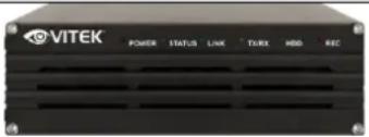 | |
| Power Supply Unit(Power Cable & SMPS DC12V 5A Adapter) | 1 EA | 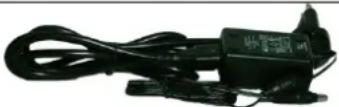 |
| CD (User's Manual, IP Installer and etc) | 1 EA |  |
Table 2 : VT-IPSN16M Packing list
2. Hardware description
2.1. VT-IPSN16M Front View
Picture 2 : VT-IPSN16M Front panel
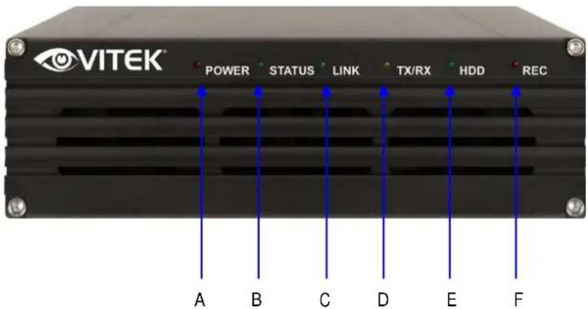
| PART | DESCRIPTION | |
| A | POWER LED | Red LED is on when power is provided. |
| B STATUS LED | Indicates the status of operation & shutdown of VT-IPSN16M.Green LED turns on during normal operation after VT-IPSN16M boots. | |
| C LAN LINK LED | Indicates the status of access to LAN | |
| D | LAN(Tx/Rx) LED | Yellow light blinks with data transmission over LAN. |
| E | HDD LED | Green light blinks when formatting or recording on HDD. |
| F | RECORDING LED | Red light blinks when recording to HDD |
Table 3 : VT-IPSN16M Front panel
Beep Sound Description
| Name | Description | |
| 1 POWER ON One short Beep | when power is turned on. | |
| 2 | SYSTEM READY | Two Beep's after boot-up |
| 3 | POWER OFF | Two short Beep's on power down |
| 4 HDD ERROR | Beep's continuously for five seconds when HDD has an error. | |
| 5 | FACTORY DEFAULT BUTTON | Beep's one time (0.5 sec) after three seconds and then beep's three times shortly after another three seconds. |
Table 4 : VT-IPSN16M Beep Sound
2.2. VT-IPSN16M Rear View
Picture 3 : VT-IPSN16M Real panel

| PART DESCRIPTION | ||
| A Cooling FAN HDD Cooling FAN | ||
| B | USB | USB port (reserved for future use) |
| C | Factory Default Switch | To Factory Default SystemPush the switch for 7 secs after system booting. |
| D LAN | LAN port | |
| E COM RS 232 | ||
| F Power | DC 12V 5A | |
| Do not cycle power until HDD and Fan have stopped | ||
| G Power Switch | Used to switch on/off power | |
| Do not cycle power while formatting HDD (may damage HDD) | ||
Table 5 : VT-IPSN16M Rear panel
2.2.1. COM Port Description
Below image illustrates PIN No. of COM Port, Numbers are displayed in order from the left. For RS-232 connection, RXD & TXD & GND are used only in general, RXD and TXD should be crossed to communicate properly in case it connects with PC one by one.

Picture 4 : COM Port Description
3. VT-I PSN16M Installation and Basic Setup
3.1. Before Installation
• Carefully read the User's Manual.
- Check Network Configuration (IP Address, Network Mask and default gateway)
- Obtain an IP address for the VT-IPSN16M.
3.2. Factory Default Settings
The following table shows the factory default condition. Please refer to this when you need to change the values in the admin menu.
| Factory Default | |
| Admin ID root | |
| Admin password root | |
| IP address 10.20.30.40 | |
| Network mask 255.255.255.0 | |
| Gateway 10.20.30.1 |
Table 5: Factory Default
Note: Factory default Admin ID and Password are all lower case...
3.3. Installing VT-IPSN16M
For installation of VT-IPSN16M, please follow the steps below.
- install the VT-IPSN16M in place with adequate ventilation
- Connect the VT-IPSN16M to the Network through the LAN port.
- Connect the power supply of VT-IPSN16M.
Refer to the following sections for programming and viewing
• Network Configuration: Refer to "IP Installer User's Manual"
- Camera Configuration: Refer to "Vitek Admin Menu User's Manual"
• Service Configuration: Refer to "Vitek Admin Menu User's Manual"
4. Software Installation
- Run IP Installer Software from the CD program on a computer that is on the same network as the IP camera.

- Start IP Installer, by double clicking the icon "IP Installer"
- After the program has started, the main window of IP Installer program will appear on the screen as shown below.

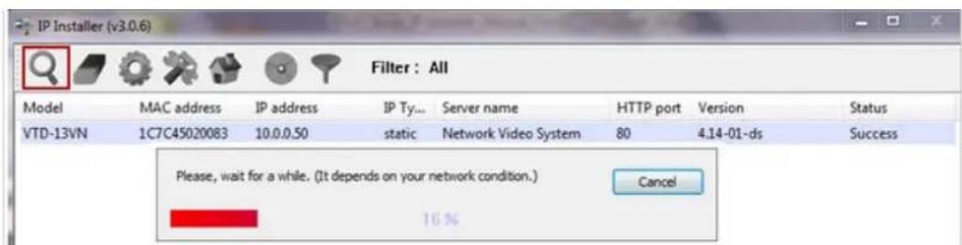
- Search for the installed camera on the network by clicking the search product icon, the camera should appear as the image below. The default IP address is 10.20.30.40
- To assign an automatic IP address to this camera within the network, click the "Automatic IP Setup" icon

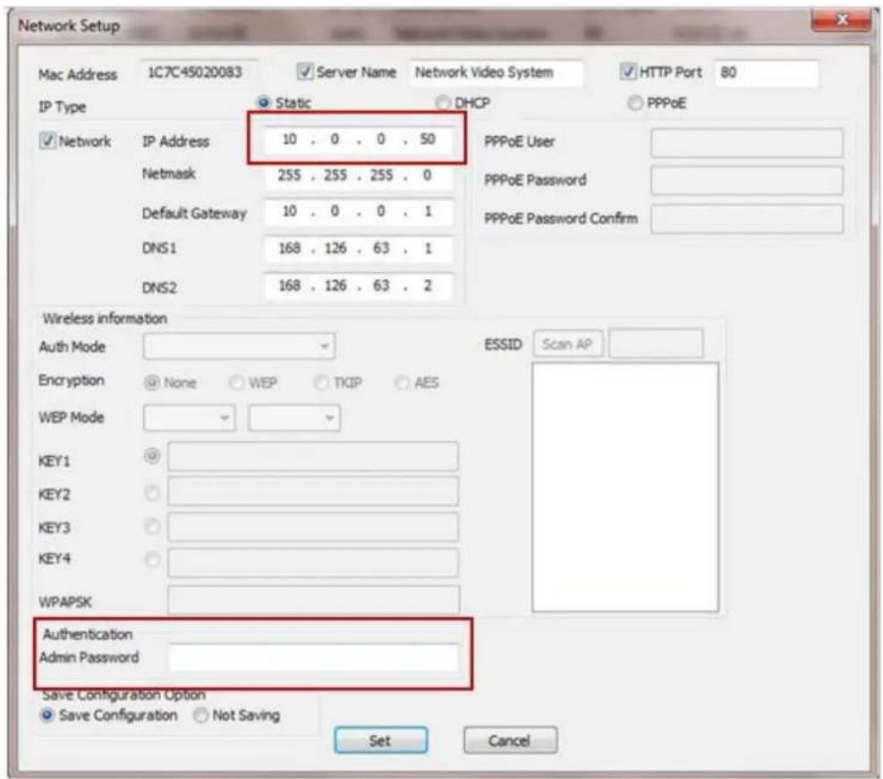
- Verify the Automatic IP address provided, enter the default password root and then click Set as shown below.
- After the camera was configured by the program automatically, you will be able to get access by
a) Right click over the camera information, "Go Product Homepage"

b) Click over the icon "Connect Product Homepage"

- From the Home Page, you can "Live View" or administrate "Admin" the camera.

Model : VT-20VN-M, Firmware ver 4.16-B2-ds-VI Homepage ver 4.16-B2_VI for Network Video System
On Live View you will be able to see live video from your camera.

NOTE: For more information, refer to Section 11. ENVI Admin Menu on page 36.
5. IP Installer: Introduction
IP Installer is a proprietary utility program for Vitek IP products. It enables users of Vitek products to search their network for any Vitek network camera, video server, or network video recorder no matter what IP address it has. By using IP Installer, users will be able to facilitate network setup process for Vitek products deployment.
• Runs on Microsoft Windows operating system (XP, Vista, 7, 8)
• Search for Network Cameras, Video Servers, and Network Video Recorders
• Capable of firmware updating
• Support automatic and manual IP setup
6. Installing and Uninstalling
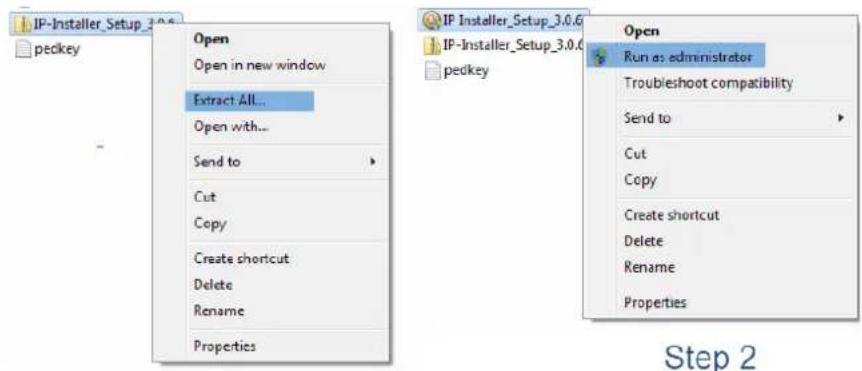
** It's recommended to install this program as an administrator **
Step 1
6.1. Installing IP Installer
If the program is started from the CD supplied with Vitek products, insert the CD in to CD/DVD tray and check the installation file. If it is download or copied from the Internet or any other media, locate the file from the PC's hard drive. You will see the icon as shown with the file name IP Installer_Setup_x.x.x.exe. The actual file name in your case may vary as the version changes. Double click the icon to star installation.

You may be prompted to continue running the installation program.
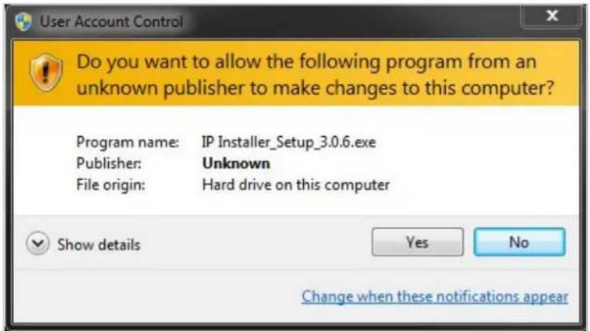
Click Yes button, then the following window will be shown on the screen.
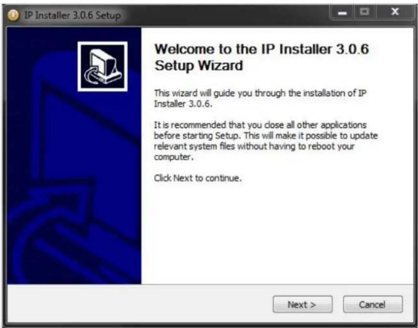
To continue the installation, click Next. The following window will be displayed for location to install.

The default location for installation is C:\Program Files\IP Installer. It is recommended to install in this folder, if you want to change it to a different location, click the Browse button to choose location. Now click the Install button. You will see the progress of the install as shown below.
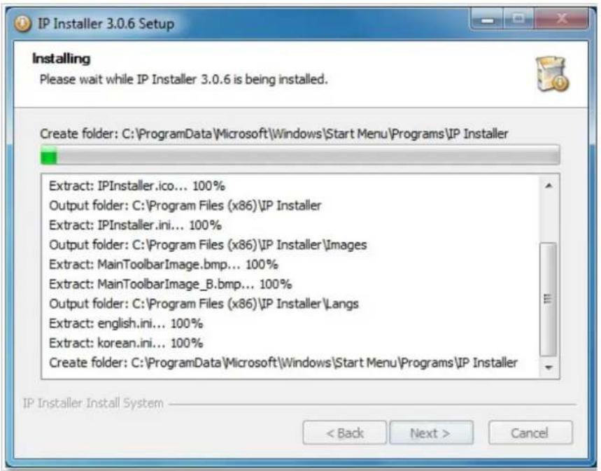
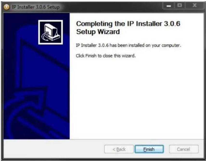
When the files are done copying, the following window will be shown. Click the Finish button to complete the installation.
6.2. Uninstalling IP Installer
If you want to remove the IP Installer program from your PC, click Start > All Programs > IP Installer > Uninstall.

You may be prompt to continue running the uninstall program.
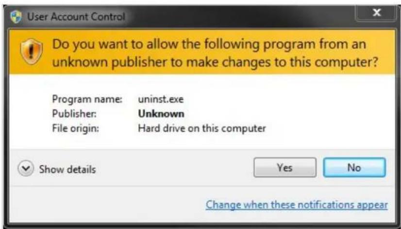
Click on the Yes button, then the following window will be shown on the screen.
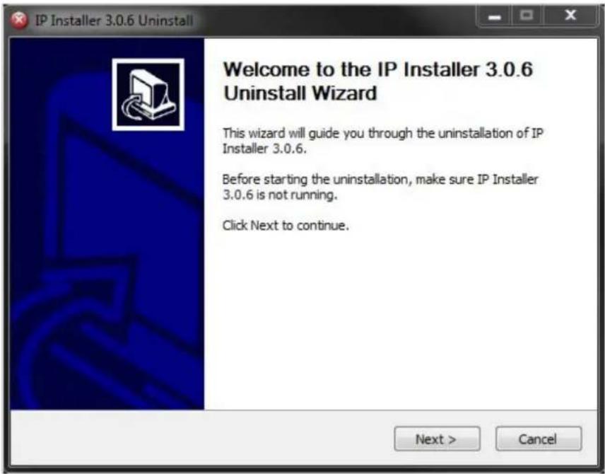
Click on the Next button and you will see the following window.

Click on the Uninstall button to start removing the IP Installer program from your computer. The following window will be displayed.

Click on the Finish button to close the window
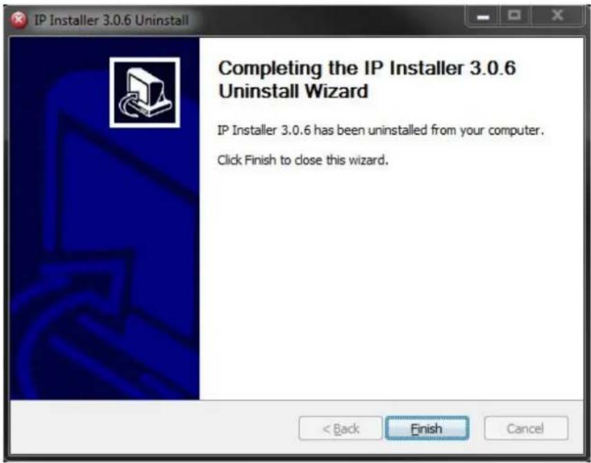
7. Using IPInstaller
7.1. Starting the Program
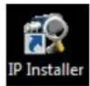
Once IP Installer program has been installed on your computer, a shortcut icon should be created on the desktop of your computer. You can start IP Installer by double clicking the icon.
Or you can also start the program by clicking Start > All Programs > IP Installer > IP Installer as shown below.
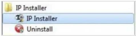
After the program has started, the main window of IP Installer program will appear on the screen as shown below. There are no network devices shown, as it is the first time running the program and nothing has been registered.

 | Search Product | Scan the network and shows the list of all the Vitek products that IP Installer program found. |
 | Clear Product List | Clear the Vitek products list created by searching the network. |
 | Automatic IP Setup | Configure the network setting of selected IP device in Automatic mode. |
 | Manual IP Setup | Configure the network setting of selected IP device in Manual mode. |
 | Connect Product Homepage | Connect to the server homepage of the selected IP device. |
 | Update Firmware | Update the firmware of the selected IP device. |
 | Filter Configuration | Define the range of MAC and IP addresses to search. |
7.2. Search Product

Make sure that your Vitek products are powered and connected to the network, and then click the Search Product button. A status window will pop up to show the progress of the search. Wait until it reaches 100%, or you may press the Cancel button to stop the at any given time and proceed with the results made until that moment.
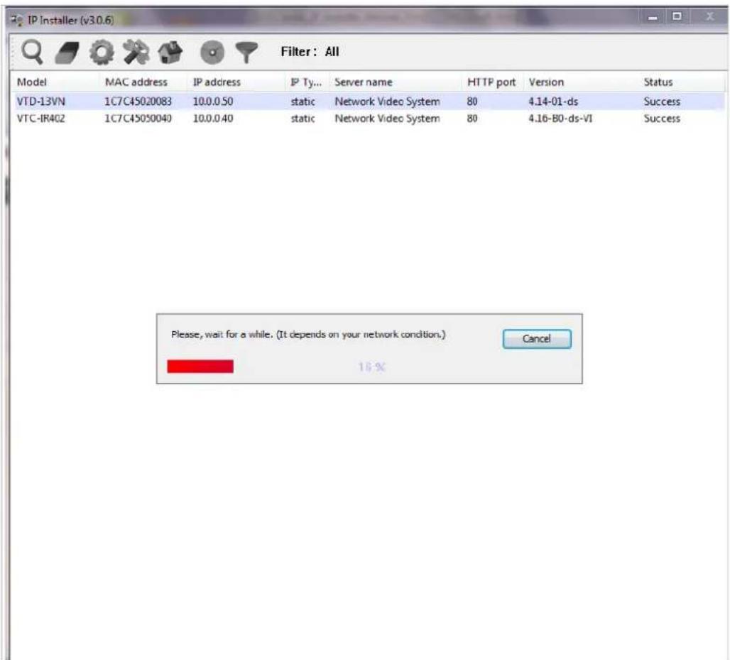
After searching is completed 100%, the IP Installer program will display the IP devices found.

If you want to clear the list of the IP Devices from the window, click Clear Product List button from the Main Toolbar.
7.3. Manual Network Setup

Configuring the network parameters of the devices in the list can be started either by highlighting and right clicking mouse button or by clicking Manual IP Setup button on the main Toolbar.

When one IP device is selected, the following screen will appear
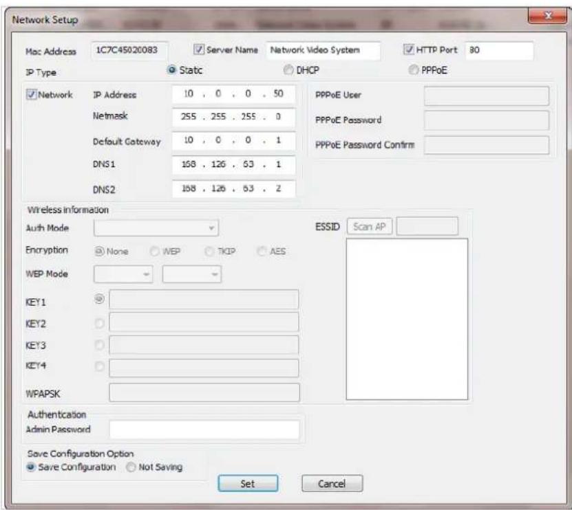
| MAC Address | MAC address of the selected device is shown. |
| Server Name | Input desired name of camera i.e. Lunch Room |
| HTTP Port | Input port number to access IP devices homepage via web. Default port is 80 |
| IP Type | Select the type of address (Static / DHCP / PPPoE) Use STATIC for manual IP setup |
| Network | General network parameters are required in this part. Please contact your network administrator for detail.(IP Address, Netmask, Default Gateway, DNS1, DNS2) |
| Authentication (Admin Password) | Password for the IP device. (Default password for Vitek products is “root” unless already changed) |
| Save Configuration Option | Select whether the configured contents is to be saved in the Camera memory or not. · Save Configuration: Changed values will be saved in the Camera memory of the device, which means the changes are permanent. · Not Saving: Changed values will not be saved in the Camera memory, which means if the IP device is turned off the changes are lost and the previous setting will be applied back. |
Click Set button to apply the changed values to IP device. If you don't want it, click Cancel button.
When two or more IP devices are selected
You can select two or more IP devices at the same time by clicking one after another while CTRL key is pressed. The result is shown as below.
To configure the network parameters of those devices, click the right mouse button or click
Manual IP Setup icon on the main Toolbar with multiple IP devices selected as shown above.
Then the following window will show up.

You can modify the value of each changeable field by clicking it. The following shows an example of entering a new value to a field.
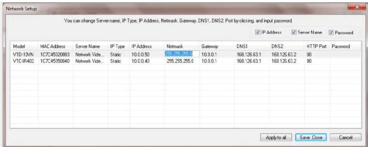
| Model | Model Numbers of the IP devices that you selected. |
| MAC Address MAC address of the selected device is shown. | |
| Server Name Name of the selected IP device. | |
| IP Type | How to assign IP address to the device (Select Static here for Manual IP Setup) |
| IP address, Netmask, Gateway, DNS1, DNS2 | General network parameters are required in this part. Please contact your network administrator for detail. |
| HTTP Port | HTTP port number of the IP device for web access to homepage. |
| Password | Password for the IP device.(Default password for Vitek products is “root”) |
If you click Apply to all button after changing just a field of one IP device, the remaining IP devices will have the same value for that parameter. In this case, each device's Server name and IP Address field will have +1 incremented value added to the original value. For example, if the first IP device has been given the server name of NetCam and Apply to all button is pressed, it will be automatically changed to NetCam1 and the next IP device will have NetCam2 and so on. The same applies to the IP address field.
For Password field, the entered information doesn't increment but will use the same data.
In using Apply to all, you can choose which field is affected. Put check marks only on the field you want to use this automatic action as below.
IP Address
Server Name
Password
Click Save & Close button to save the changed values in the camera memory of all the IP devices and close the Network setup window.
7.4. Automatic Network Setup

Configuring the network parameters of the devices in the list can be started either by clicking right mouse button or by clicking Automatic IP Setup button on the main
Toolbar. Before starting the setup, you first need to choose the one to be configured. In this setup mode, IP Installer program checks your local network and assigns available IP addresses to the IP devices. You have a choice of using those automatically assigned IP addresses, or you can just enter other IP addresses as you desire.
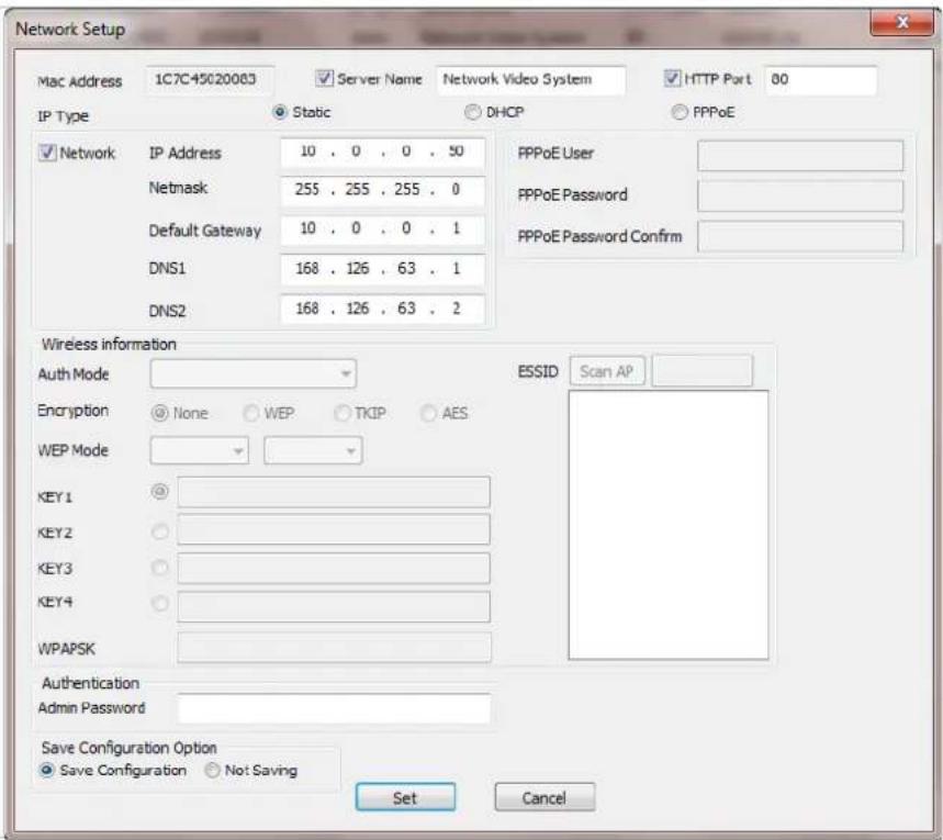
| Server Name Name of the selected IP device. | |
| HTTP Port | HTTP port number of the IP device for web access to homepage. |
| IP Type | How to assign IP address to the device (Select Static here for Manual IP Setup) |
| Network | General network parameters are required in this part. Please contact your network administrator for detail. (IP Address, Netmask, Default Gateway, DNS1, DNS2) |
| Authentication (Admin Password) | Password for the IP device. (Default password for Vitek products is “root”) |
| Save Configuration Option | Select whether the configured contents is to be saved in the Camera memory or not.Save Configuration: Changed values will be saved in the Camera memory of the device, which means the changes are permanent.Not Saving: Changed values will not be saved in the Camera memory, which means if the IP device is turned off the changes are lost and the previous setting will be applied back. |
Click Set button to apply the changed values to IP device. If you don't want it, click Cancel button to restore the previous values.
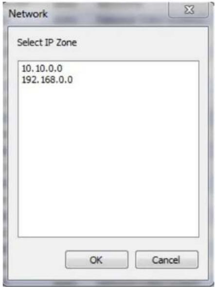
Note: If your network has more than one IP address Zone at the same time, the confirmation window will be displayed as below. You need to choose the one you are going to use for your IP devices.
7.5. Using DHCP Server
If your network has a DHCP server running for assigning IP addresses, you may choose to let it assign IP addresses to the IP devices on the list. To do that, first open the Network Setup window either by Manual IP Setup or Automatic IP Setup procedure. Choose DHCP in "IP Type" selection, then IP Address, Netmask, Default Gateway field in Network setup area on the window will be disabled to input as shown below.

For setting up other fields on the setup window, refer to Section 10.3 Manual Network Setup on page 24. After filling the fields with appropriate values, click Set button to apply the changed values to IP device. If you don't want it, click Cancel button to restore the previous values.
7.6. Using PPPoE
If your network environment is based on PPPoE connection, you'll need to choose PPPoE on IP Type selection. First open the Network Setup window either by Manual IP Setup or Automatic IP Setup procedure. Choose PPPoE in IP Type selection, and then all the fields in Network setup area on the window will be disabled. The network settings such as IP Address, Netmask, Default Gateway and DNS are no longer available to enter. You only need to enter the Server Name, HTTP Port number, and login authentication for your PPPoE connection.
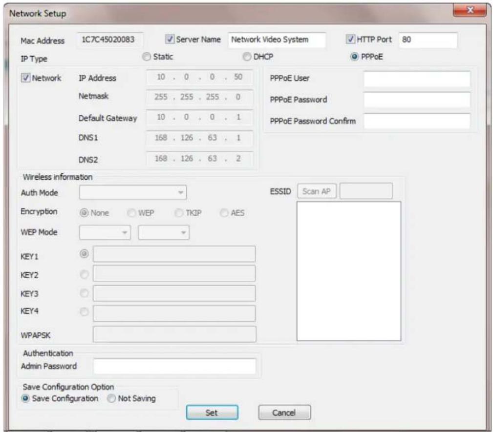
MAC Address MAC address of the selected device is shown.
Server Name Name of the selected IP device.
| HTTP Port | HTTP port number of the IP device for web access to homepage. |
| IP Type | How to assign IP address to the device (Select PPPoE in this mode) |
| PPPoE | User Authentication for PPPoE Connection.PPPoE User: Enter User ID.PPPoE Password: Enter Password for the User ID.PPPoE Password Confirm: Enter the same Password again. |
| Authentication (Admin Password) | Password for the IP device.(Default password for Vitek products is “root” unless already changed) |
| Save Configuration Option | Select whether the configured contents is to be saved in the Camera memory or not.Save Configuration: Changed values will be saved in the Camera memory of the device, which means the changes are permanent.Not Saving: Changed values will not be saved in the Camera memory, which means if the IP device is turned off the changes are lost and the previous setting will be applied back. |
Note: After setting up the network for the IP devices, make sure the IP devices are accessible on the network from your computer. It can be done by running Live View function of the homepage of the IP device's built-in server. Refer to Section 10.9 Live View on page 34 for more information.
7.7. Updating Firmware
Once IP devices are searched and shown on the screen as functioning successfully, you can update the firmware of them in IP Installer program. To do that, first check the firmware version of the device, which you can find on the IP Installer window.
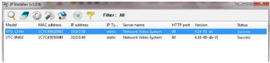

In the above picture, the firmware version of this product is 4.14-01-ds while the latest firmware version available is 4.16-B0-ds-VI as you could see at Vitek's homepage (http://www.vitekcctv.com/Downloads.asp). If you decide to update the firmware, first
create a folder on your computer for the update firmware, than download the latest firmware to that folder.
Then select the IP device to be updated on IP Installer window, then click Update Firmware button from the toolbar. The following window will be displayed.

You may find the Password field is empty on the window shown above. If so, click the Password field of the IP device and enter the proper password for the device. You are not allowed to update the firmware if the correct password is not provided.
After the password is entered, the Start Update button will be enabled now. Click the button to see the following window for selecting the folder where the file has been saved. Highlight the folder than click OK.

After clicking OK the following window will be displayed.
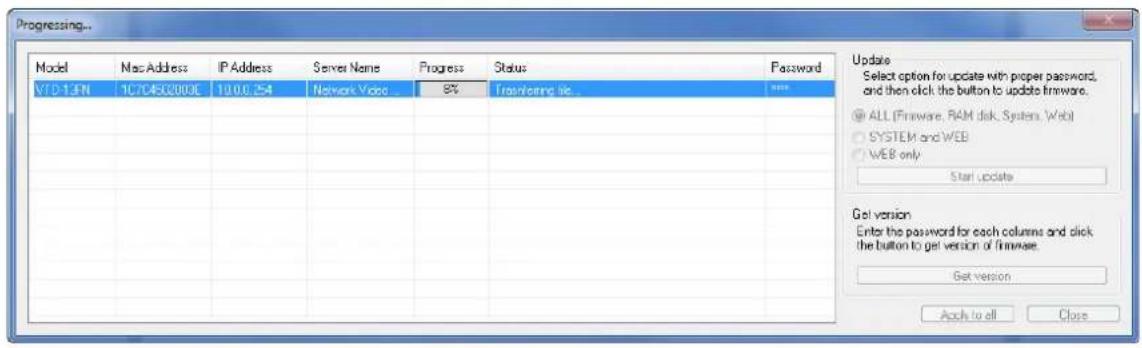
Note: Do not CLOSE window until completed, to avoid permanent damage to the camera.
You can also select multiple IP devices at the same time, and have them start firmware updating in a single step. Select the files to update by holding CTRL key and selecting which IP devices to update
Click Start Update button. You will see the update window brought up with multiple IP devices listed.
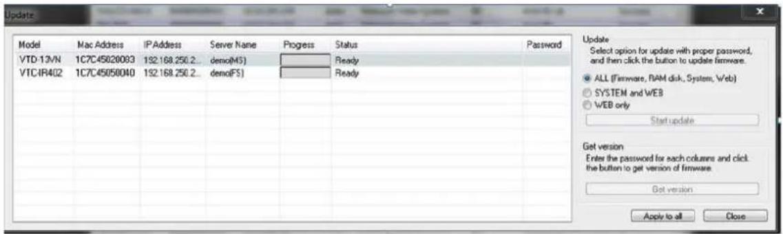
The rest of the procedure is the same as in the firmware update case for a single IP device.
7.8. Filter Configuration

When you need to search only for the IP device having a specific range of MAC or IP addresses, you can do it by using this feature. To set the search condition, click Filter Configuration button on the Toolbar, then the following window will show up on the screen.

The first six HEX characters are already filled in with 1C:7C:45, which is the MAC prefix for Vitek products. Put a checkmark in MAC Address or IP Range to set the range for searching.
You can set the range of IP addresses to scan as shown below. In this example, all the IP devices having MAC address starting with 1C:7C:45 will be listed on the result window after scanning.
Or you can look for a single IP device having a specific IP address as below.
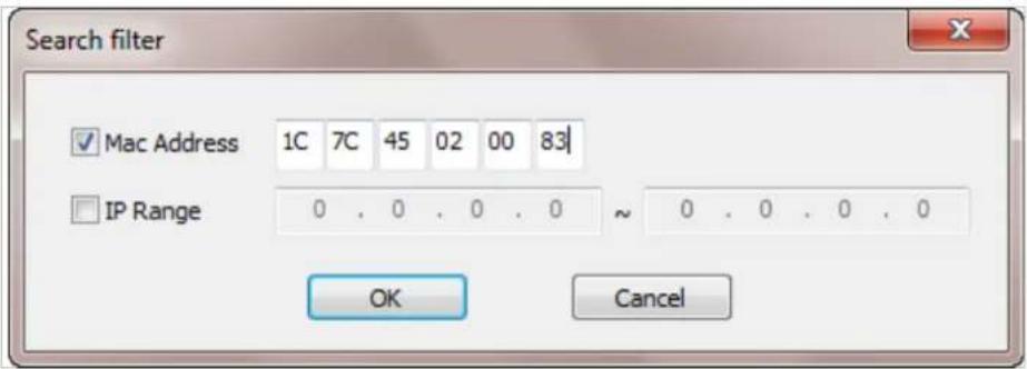
IP Address range for searching can be entered as follows.
You may even set both MAC Address and IP Range together at the same time.
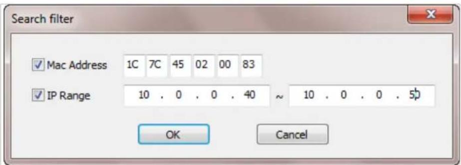
After setting the searching range as explained above, click OK button. Then IP Installer program
window will show the searching range on the top right portion of the window as shown below.
![IP Installer (v3.0.6) Filter : Mac[1C7C45020083] IP[10.0.0.40-10.0.0.50] Model MAC address IP address IP Ty... Server name HTTP port Version Status VTD-13VN 1C7C45020083 10.0.0.50 static Network Video System 80 4.14-01-ds Success VTC-IR402 1C7C45050040 10.0.0.40 static Network Video System 80 4.16-B0-ds-VI Success](/content/2026/06/1213747/images/a11429223a3a4e027af81f36bffd57f572029342f9c95ae4b8d69bd663540613.jpg)

To start searching with this condition now, click Search Product button on the toolbar.
The program will start searching and show the result after a moment.
7.9. Live View
Once searching and configuration on IP devices are done, you should make sure that the IP devices are accessible with the new settings. The best way to do it is by connecting to the homepage of each IP device's built-in server, and starting Live View feature.
Select Go Product Homepage when you click the right mouse button on the IP device to test.
![IP Installer (v3.0.6) Filter : Mac[1C7C45020083] IP[10.0.0.40-10.0.0.50] Model MAC address IP address IP Ty... Server name HTTP port Version Status VTD-13VN 1C7C45020083 10.0.0.50 static Network Video System 80 4.14-01-ds Success VTC-IR402 1C7C45050040 10.0.0.40 Go Product Homepage Setup Product IP m 80 4.16-B0-ds-VI Success](/content/2026/06/1213747/images/7b9d4f7f2c5b2faea355ffdc85dad629fbff6431568fb6a9d381d603c3363c98.jpg)

If you select Go Product Homepage, the homepage of that device's built-in server will be opened on a new Web browser window as shown below. This is the same result when you click Connect Product Homepage button from the Main Toolbar.
Home | Live View | Admin

Model : VTD-13VN, Firmware ver 4.14-01-ds
Homepage ver 4.14-01_VI for Network Video System
Click Live View on the top right of the window, then ENVI Series Viewer ActiveX program will be started. If you have not installed the ENVI Series Viewer program before, it will ask for a confirmation to install it. Allow it and you will be able to find out whether the configuration by IP Installer program is properly done.
Note: Refer to Section 19. ENVI Series Viewer on page 79 for detailed information about the ENVI Series Viewer ActiveX program.
8. ENVI Admin Menu
After connecting to a VITEK ENVI Series camera via web browser, you'll find the web page as shown below. The upper rightmost item of the menu is Admin; this is where you can set up most of the features in the VITEK camera you're connected to.

Model : VTD-13FN, Firmware ver 4.14-01-ds Homepage ver 4.14-01_VI for Network Video System
8.1. Entering Admin Menu
Click Admin then you'll see a login window. In the login window, enter root for both ID and password as they are the factory defaults. Press Enter key or click OK.
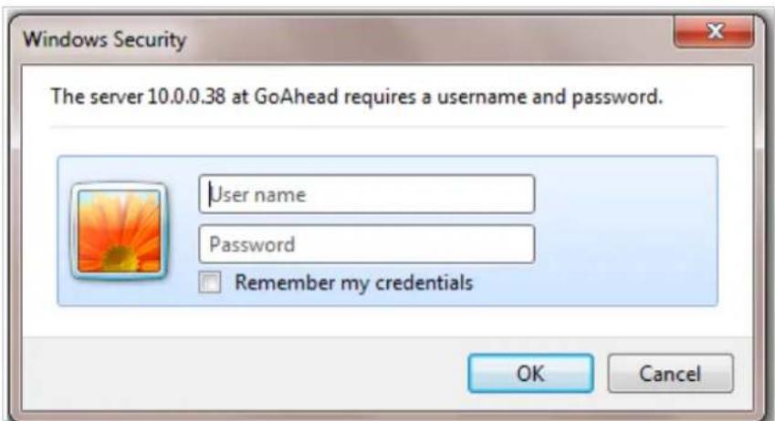
Now the Admin Menu will be displayed as shown below. This will guide you to the top level menu items, which are Quick, System, Network, Device, Advanced, Recording, and Utilities. Clicking any of these top level menu items will display submenu items and brief descriptions.

8.2. Admin Menu Structure
The following table shows the hierarchy of the Admin menu structure that we're going to deal with in this manual.
9. Quick Configuration
In Quick Configuration, you will be able to set up many of the essential parts of the configuration in a simple manner without going into details. Selecting Quick Configuration gives you the menu as seen below. You can perform each setup by clicking the one you would like to configure.
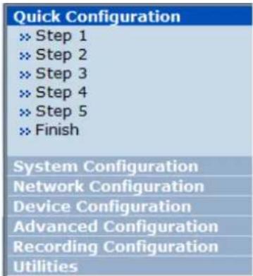
9.1. Step 1: Changing Server Name
Click Server Name on System Configuration menu, then Server Name Setup windows will be displayed. Refer to Section 13.1 Server Name Setup on page 38 to see how to change the server name.
9.2. Step 2: Time Setup
Click Date & Time on System Configuration menu, then the Local Date & Time Configuration window will be displayed. Refer to Section 13.2 Date & Time on page 39 to see how to set up.
9.3. Step 3: Network Setup
To make a connection to the Internet, it is required to figure out the type of the Internet service you're using. Refer to Section 14. Network Configuration on page 42 to see how to set up.
9.4. Step 4: IPCCTVDNS.COM
When VITEK Server is used in a Dynamic IP environment, it is required to utilize IP-CCTV DNS feature. Refer to Section 36 IP-CCTV DNS Setup on page 141 to see how to set up.
9.5. Step 5: Recording Configuration
Vitek cameras with MicroSD card can be configured for recording options in this section. Refer to Section 17.2 Recording Configuration with microSD card on page 71 to see how to set up
9.6. Finish
After clicking Finish all changes will be saved automatically to the camera/server
Save Configuration
- Changes to configuration will be saved automatically for this model.
Back
10. System Configuration Menu
When you click on System Configuration item on Admin Menu, the following sub menu will be displayed.

10.1. Server Name Setup
Click Step 1 on Quick Configuration or Server Name under System Configuration then the following will be displayed and you will find out the system information such as model number of the VITEK camera, server name (camera name), MAC address (serial number), firmware version, and Web image version.
Server Name Setup
| Product model name | VTD-13VN |
| Server name | Network Video System |
| Mac Address (S/N) | 1C:7C:45:02:00:83 |
| Firmware version | 4.14-01-ds |
| Webimage version | 4.14-01_VI |
Back
Apply
Notice : The server name can be 21 alphanumeric or 10 unicode.
As an administrator, you can change the name of the camera/ server, but other values are not allowed to be changed. To change the camera/ server name, enter a new name in the Server Name field. You may use up to 21 alphanumeric or up to 10 Unicode characters. Tab or any other special characters are not allowed. Click Apply button to save the setting and it will take effect immediately.
10.2. Date & Time
Click Step 2 on Quick Configuration. Or Date & Time under System Configuration Fill the Date and Time fields with your local time and date information. If you're in a different time zone, put a checkmark on Change Time Zone, then select the correct region from the dropdown list to make the time zone change, you need to click Apply button and reboot the system.
Local Date & Time Configuration
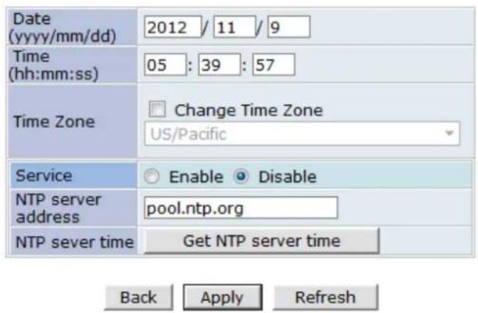
Notice : If you change the 'Time Zone' and click 'Apply' button, we strongly recommend to reboot this Network Video System.
If you want to retrieve the exact current time from a NTP server on the network, click Get NTP Server Time button. Clicking Refresh button will display the date and time retrieved from the camera. Then click Apply button to save it.
Note: In order to retrieve Time and Date information from a NTP server, you need to put NTP server address in advance of setting up, such as pool.ntp.org.
10.3. Admin Password
To change the password for the administrator, click Admin Password in System Configuration menu.
Administrator's Password Configuration
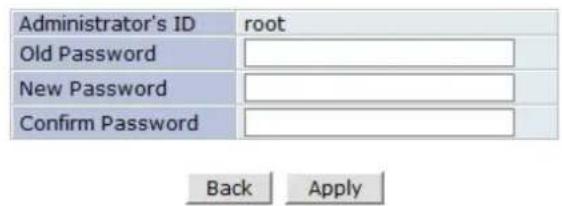
Notice : The password must be alphanumeric, within 4 \~ 23 characters.
Default ID for admin account is fixed as "root" and is not allowed to change. In Old Password field, enter the current password. In both New Password and Confirm Password fields, enter the same new password. The password must be between 4 and 23 alphanumeric characters. Click Apply button to put it into effect.
Because you have replaced the password with a new one, the existing network connection made with old password to VITEK camera is lost now. You will have to reconnect to the VITEK camera using new password.
10.4. Access Control
Click Access Control on System Configuration menu. The following windows will be displayed.
Access Control Configuration
Access Permission
Full Access (View and control camera & audio without permission)
Limited Access (In accordance with an user's permission)
Back Apply
From the Access Permission window, select either one you would like to use. Click Apply button to save the change.
• Full Access: Any user can access the camera/server and use all the features without limits.
- Limited Access: Only registered users can access the camera/server and have limited privileges.
10.5. User Registration
You can add, modify, or delete users for your VITEK camera/server here. Once registered as Limited Access setting, the user can access the VITEK camera/server with some limited privileges.
10.5.1. Add
To add a user, click User Registration on System Configuration menu. When Add is selected, you can add users and define their passwords, names, and access permission levels respectively.

Enter a User ID between 4 and 23 alphanumeric characters. In both Password and Confirm Password fields, enter the identical password respectively. The password must be between 4 and 23 alphanumeric characters. In Name filed, enter the user's name up to 23 alphanumeric characters.
Now select one of the four items from System Resource Access Permission, which defines the permission level for registered users to the VITEK camera.
| System Resource Access Permission | |
| ○ | All Channels Access |
| ○ | General Access (only live viewing access) |
| ○ | No Access |
| ○ | Selective Access |
- All Channels Access: User can use all the features except for Configuration in Admin Page.
- General Access (only live viewing access): User can only use Live View feature.
- No Access: User is not permitted any of the features.
- Selective Access: User is allowed to use only the selected features. With this item selected, you can now configure the details under this menu for the user.
VITEK cameras may have multiple VS Modules registered in it. When you click on any of the Enable check boxes, other fields in that row are now enabled to select.

• VS Module ID: VS Module is a network device that has been registered in the VITEK camera
- Camera No.: Among the cameras of the VS Module select one to set up. (between all, 1or2)
- Alarm Control: Determine if Alarm control is to be allowed. (Feature not available on this model)
- Audio Control: Determine if Audio Control is to be allowed. (Feature not available on this model) After finishing the registration process, click Apply button to add the user.
10.5.2. Edit
To edit a user account, select Edit. In this part, you can modify the existing user's name, password, and access permission. User ID is not allowed to change. Once selecting a user ID to edit, the procedure is the same as in Add section.
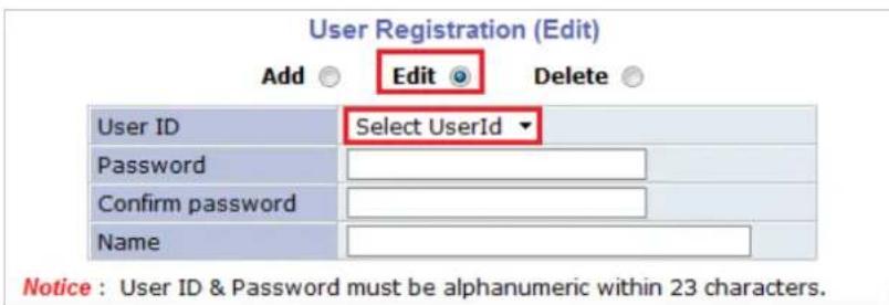
To see existing users, click Select UserID, and select a user to be edited from the dropdown box. Then you can change the password, name, or access permission, and click Apply button to save the setting. Setup of Access Permission can be done the same way as in the Add section.
10.5.3. Delete
To delete an existing user, select Delete.

From the list of the users, select a user to delete. Click Delete button to confirm the deletion.
11. Network Configuration
Configuring the network is dependent on how an IP address is assigned in Ethernet-based environment, which is static IP, dynamic IP (DHCP), or PPPoE.

| Network Configuration | |
| This category shows the detailed method for network system. | |
| » Network Configuration | Configuration of Network(IP,Netmask,DNS). |
| » Network Ports | Modification of HTTP and other application network port numbers. |
| » Bandwidth Control | Configuration of bandwidth control. |
| » View Network Status | View of Network Status. |
| » Network Status Notify | It sends IP address by e-mail when IP address is allocated by DHCP(or PPPoE). |
| » IP-CCTV DNSTM | Configuration of dynamic IP registration of Network Video System. |
| » Port Forwarding & UPnP | Configuration of Port Forwarding & UPnP(Universal Plug and Play). |
| » RTP/RTSP | Configuration of RTP/RTSP. |
11.1. Static IP Configuration
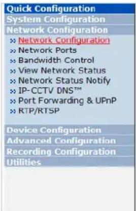
Select Network Configuration under Network configuration
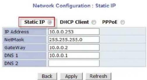
For static IP, select Static IP and input IP address, NetMask, Gateway, DNS1, DNS2 and click apply to save settings. After apply, program will ask to close web browser for updates, which will take 20\~30 seconds. If Back button is clicked all values will be discarded. If Refresh button is clicked, the program will load previous values.
11.2. DHCP Client Configuration
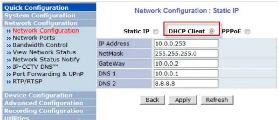
To use DHCP a DHCP server must exist in the network environment. Select DHCP Client from Network Configuration, click Apply. And all information needed will be filled in automatically
11.3. PPPoE Configuration
PPPoE is used to connect VITEK products to a PPPoE modem provided by the ISP. Since PPPoE needs verification, ID and a password are necessary to access the network. Type in PPPoE user ID and password

11.4. Network Ports
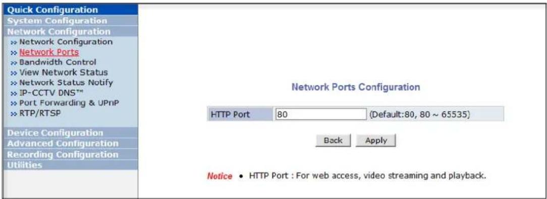
In this configuration, you set up the HTTP port for VITEK cameras to communicate with the Client PC. HTTP Port is the network port that is used when a Client PC connects to the VITEK camera Web page. It can be assigned between 80 and 65535. The default value is 80.
Note: If the HTTP port number is changed to a different value than default (80), make sure the new HTTP port number goes together with the VITEK cameras IP address. For example, when a VITEK cameras IP address is 192.168.1.100 and the HTTP port is 8080, you will have to enter http://192.168.1.100:8080 to connect to the camera.
11.5. Bandwidth Control Configuration
Bandwidth control is for limiting maximum network traffic. If it is enabled with Bandwidth limits, maximum data size transferred from VITEK cameras won't exceed bandwidth limits set by users. If transferred data is exceeded, part of the data will be randomly lost.
If multiple users try to access a VITEK camera when bandwidth control is enabled, users connected to the VITEK camera will share network bandwidth limit.
Bandwidth Control Configuration

Notice The bandwidth limit should be over 32. MPEG-4 or H.264 streaming can be affected by this setting.
Note: This bandwidth control feature works well in M-JPEG video transmission. But, for H.264, dropping data packets may cause low quality of video, so it is recommended to utilize CBR and frame rate control instead of bandwidth control for H.264 video. Refer to Section 15.2 Camera & Motion on page 53 For more info on CBR and Frame rate
Note: Network Bandwidth control is managed by the VITEK camera and it drops any data packets if required, thus you may experience slow connection when this feature is enabled.
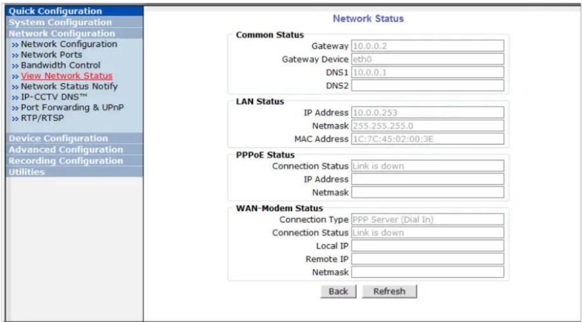
11.6. View Network Status
This menu shows network status of VITEK cameras.
11.7. Network Status Notify
This feature helps to send updated network status information to registered email address if any changes happen. This function will work under DHCP or PPPoE.
If Network Status Notify is set to Enable, VITEK cameras network status will be emailed to a specific person in case of the following events:
- When it is set to Dynamic IP in the Network Configuration menu, and the VITEK camera has been given a new dynamic IP address and connects to the network. Or,
- When it is set to PPP Client on WAN-Modem menu, and the VITEK camera has been connected to the network with ISP or PPP server.
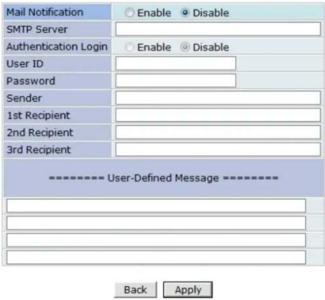
To configure, click Network Status Notify on Network Configuration menu. The following window will be shown.
Network Status Notification
Notice : It sends IP address by e-mail when IP address is allocated by DHCP(or PPPoE).
First, select Enable to use the feature. Then enter the address of the SMTP server which is needed for email service. If your SMTP server requires a user ID and a password for authentication, you will have to Enable Authentication Login and enter the user ID and Password.
In Sender field, enter your email address or other meaningful words that will show the message was sent from the VITEK camera as a notification. Now enter the email addresses of the recipients in the Recipient fields, up to 3 addresses. In the User-Defined Message box, you may enter a message to explain why the message was sent. After finishing the setup, click Apply to save settings.
| Mail Notification | Enable: Send emailDisable: Do not send email |
| SMTP Server SMTP Server address for email service | |
| Authentication Login | Enable: user ID and password are required for SMTP serverDisable: user ID and password are not required |
| User ID User ID for SMTP server | |
| Password Password for SMTP server | |
| Sender | Email address of Sender or Name |
| 1st / 2nd / 3rd Recipient | Email Addresses of the Recipients (up to 3 addresses) |
| User Defined Message | Message to be included in the Notification email |
11.8. IP-CCTV DNS Setup
Note: Refer to Section 36 IP-CCTV DNS Registration on page 141 for further details on configuration
IP- CCTV DNS service provides a static & public domain name to help user's access VITEK cameras even though their IP address has changed or they are used in a local network. For proper function of IP-CCTV DNS service, products need to be accessible through the internet.
Quick Configuration
System Configuration
Network Configuration
Network Configuration
Network Ports
» Bandwidth Control
» View Network Status
» Network Status Notify
IP-CCTV DNS ^TM
Port Forwarding & UPnP
RTP/RTSP
Device Configuration
Advanced Configuration
Recording Configuration
Utilities
IP-CCTV DNS™ Setup
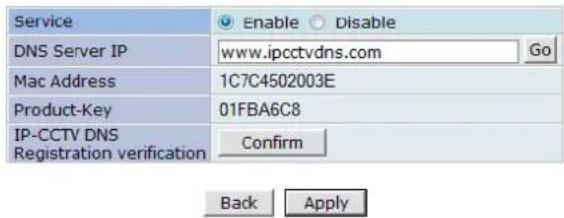
Notice : If you do not use public dynamic IP address for the remote access.
please skip this step.
This is related with www.ipcctvdns.com.
Different IP address or URL must follow the same protocol of
www.ipcctvdns.com
If you click Confirm button, you can verify registered URL on IP-CCTV DNS.
If product is not registered on IP-CCTV DNS, you can not verify registered URL.
11.9. Port Forwarding & UPnP
UPnP(Universal Plug and Play)is a kind of network protocol to help users to find and configure network products in the same local network area. Port forwarding is to assign a certain network port to a network product so users can access it from outside of the Local Area Network. Generally, port forwarding can be configured from the network router.
UPnP port forwarding is made up with finding an available network port, assigning it to a VITEK camera and reporting overall network configuration of a VITEK camera to IP-CCTV DNS server. Users have to register products into IPCCTVDNS server and IP-CCTV DNS service should be enabled.
There are 3 options in UPnP Port Forwarding.
- Manual: User Assigned Port issued when users can access network router (hub) and manually assign available network ports to VITEK cameras. In this case, users have to type already-assigned network ports under User Assigned port.
- UPnP: User Assigned Port is used when users want VITEK cameras to configure port forwarding of network hub with user-assigned network port. If it fails, try to change user-assigned port
- UPnP: Auto Selected Port is used to let VITEK cameras deal with all network configurations automatically.
Please note that the network router needs to support UPnP Port Forwarding. There is a limit for the maximum number of UPnP devices. If it is properly configured, results will be displayed under UPnP status.
Port Forwarding & UPnP

UPnP Status
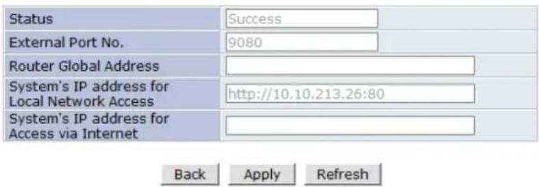
Notice : User's assigned port is the external port number of dynamic IP address. This function is quite unique when UPnP IP sharer or router are used together. If Uppn service is not activated by UPnP : User Assigned port, allocate another port.
11.10. RTP/ RTSP Setup
Factory default is Enable to be used with other manufactures VMS software's
RTSP (Real-Time Streaming Protocol) is a protocol to transfer video and audio streams over the network. Any application supporting Standard RTSP can be used for VITEK cameras. Quick Time Player or VLC program can be used with this; it may not be supported in the environment within a firewall. There are two types of usage; one for Unicast address condition and the other for Multicast address condition.
For Unicast Address:
Use "rtsp://network video server ip address/ cam0_0". If there are multiple channels, use cam0_x, x (0\~3) with each number applied. If there are multiple modules, use camx_0 x (0 \~ 3) with each module number applied.
For Multicast Address:
Use "rtsp://network video server ip address/mcam0_0". If there are multiple channels, use mcam0_x, x (0\~3) with each channel number applied. If there are multiple modules, use mcamx_0 x (0\~3) with each module number applied.
RTP/RTSP Setup
| Service | ● Enable ○ Disable | ||
| RTSP Port | 554 | (Default:554, 554 ~ 65534) | |
| RTP Start Port | 5000 | (Default:5000, 2048 ~ 65534) | |
| Camera 1 | Multicast Address | 0.0.0.0 | Disable:0.0.0.0(225.0.0.0 ~ 239.255.255.255) |
| Multicast Port | 0 | (Disable:0, 2048 ~ 65534) | |
| Camera 2 | Multicast Address | 0.0.0.0 | Disable:0.0.0.0(225.0.0.0 ~ 239.255.255.255) |
| Multicast Port | 0 | (Disable:0, 2048 ~ 65534) | |
Back Apply
Notice : This function is only for built in module. IP devices (added VS module) does not support this function.
RTSP URL for Camera 1 rtsp://(Network Video Server IP Address)/cam0_0 -> cam(0 : VS Module number)_(0:Port number)
RTSP URL for Camera1 for Multicast address (Multicast address and Port should be configured.) rtsp://(Network Video Server IP Address)/mcam0_0 -> mcam(0 : VS Module number)_(0:Port number)
| Service | Enable: Start RTSP serviceDisable: Stop RTSP service |
| RTSP Port | In normal case, use default port number 554 to connect to RTSP service. If not using port 554, enter the port number you want to use.e.g.) port number 445==>rtsp:// network video server ip address:445/cam0_0 |
| RTP Start Port | The starting number of the port for video transfer. Each time video transfer connection is made, the port number also increases. |
| Multicast Address | Address for multicast video transfer.The multicast address 0.0.0.0 is for stopping multicast. |
| Multicast Port | Port number for viewing the video with a multicast address |
12. Device Configuration
12.1. Privacy Zone
Users can set a privacy zone if a certain part of the screen needs to be unmonitored.
To set the region, click Privacy Zone from Device Configuration category.

Privacy Zone Configuration
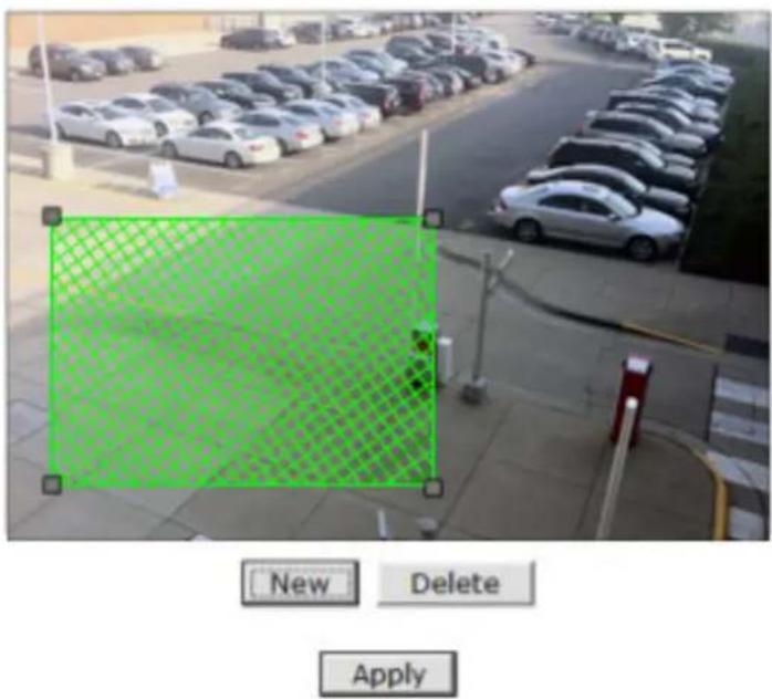
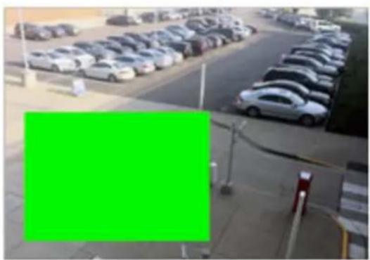
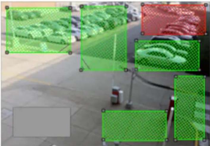
To Add a Privacy zone click New button, a Green-colored box will appear, click on the Green box and it will turn Red, at this point you can resize it by clicking and holding any corner and drag to desired size. To relocate box click and hold anywhere inside the box and drag to desired location. Click Apply when done
Privacy Zone Configuration

natural_image
Exterior view of a parking lot with rows of parked cars and a red grid overlay (no visible text or symbols)
Privacy Zone Configuration
natural_image
Exterior view of a parking lot with rows of parked cars and a green overlay (no visible text or symbols)

Privacy Zone Configuration
natural_image
Abstract collage of green rectangular frames with pixelated textures, no text or symbols present


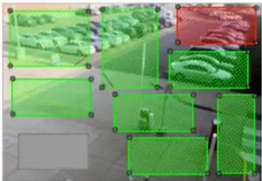
Users can add up to 8 Privacy Zones per screen by repeating above steps. If you add more than 8, an error message will display on the screen.
To delete a privacy zone, click the zone and click Delete button followed by Apply button.
Privacy Zone Configuration
natural_image
Outdoor scene with green mesh overlays and a small robot, no visible text or symbolsNew
Delete
Apply
12.2. Camera & Motion
This menu is used to set up the selection of video format, data added to video data, encoding speed, audio control, image resolution, video quality, motion detection, etc.
Click Camera & Motion on Device Configuration menu. The configuration menu will be displayed, and it may be different between VITEK cameras.

- M-JPEG: This format requires much higher network bandwidth than H.264 compression. But because of its higher quality of still image, it is adequate for detailed reviewing of stored video.
- H.264: In this format, each frame data is related to other nearby frames. For this reason, it provides much higher compression ratio than M-JPEG and is adequate for video transfer. However, if network conditions are limited dropped frames in video data is possible, the video quality can be relatively low. With VITEK Cameras, you can set the number of P-frames in the video which is independent still images between I-frames.
Note: For Dual Stream products, most of the parameters are dependent on primary stream value.
You can configure the video data format and other information to be contained in it.
Camera & Motion Configuration
| Video with Flexible Extra System data | Enable | |
| Video with user defined message | Enable | |
| Video with PPP status | Enable | |
| Video with camera name | Enable | |
| Video with server name | Enable | |
| Video with IP address | Enable | |
| Audio | Enable Disable | |
| Primary Stream | Frame Rate | 30 fps ▼ |
| Image Size | 1280 x 1024 ▼ | |
| Encoding Standard | M-JPEG H.264 | |
| Secondary Stream | Frame Rate | Primary fps ▼ |
| Image Size | 704 x 480 ▼ | |
| Encoding Standard | M-JPEG H.264 | |
Back
Apply
| » Camera Control |
| » Motion Detection |
| » Primary Stream |
| » Secondary Stream |
- Video with Flexible Extra System data: If Enabled, video data will contain UART sensor data from COM port. . (Feature not available on this model)
- Video with user defined message: If Enabled, video data will contain the user-defined data. (Reserved Field) . (Feature not available on this model)
- Video with PPP status: If Enabled, video data will contain PPP connection status. . (Feature not available on this model)
- Video with camera name: If Enabled, video data will contain the camera name. . (Feature not available on this model)
- Video with server name: If Enabled, video data will contain the server name that you defined. . (Feature not available on this model)
- Video with IP address: If Enabled, video data will contain the IP address of the video server. . (Feature not available on this model)
- Audio: (not available on all models) Select if Audio function is to be used (applies to Primary Stream only). VITEK Cameras provides 2-way audio streaming by combining microphone input with video data. Users can listen to the streamed audio through a PC and speakers.
- Frame Rate: For Primary Stream, this is the number of frames compressed in every second. You can control the network traffic with this parameter. For Secondary Stream, it can be set to a manner of 1/2, 1/4, 1/8... of the primary stream.
- Image Size: Select the resolution of each channel's video
- Encoding Standard: Select the compression method of each video, either M-JPEG or H.264 format. It is not allowed to set both channels to M-JPEG.
Below is the table of images sizes. To save the setting, click Apply button
| Video Format | SXGA | D1 | CIF | QCIF |
| NTSC | - | 704 x 480 | 352 x 240 | 160 x 112 |
| PAL | - | 704 x 576 | 352 x 288 | 160 x 144 |
| VGA | - | 640 x 480 | 320 x 240 | 160 x 112 |
| 1.3M Pixel | 1280 x 1024 | 640 x 480 | 320 x 240 | 160 x 112 |
| 2.0M Pixel | 1920 x 1080 | 640 x 480 | 320 x 240 | 160 x 112 |
12.2.1. Camera Configuration
On the lower part of Camera & Motion Configuration menu, select a channel to configure.
In the example shown below, Primary Stream is set to H.264 for compression format. Enter detailed parameters of the camera selected here.
![Camera Configuration (Primary Stream) Camera Name Camera 1 Rate Control Mode VBR Mode Image Quality Highest GOP Structure 16 [1~64] Back Apply Default Primary Stream of (H.264)](/content/2026/06/1213747/images/c28afeefb7828e1cca0746ecb5bf0014ca00a01dba403a0f000bb704f568246b.jpg)
- Camera Name: Enter the name of the channel up to 21 alphanumeric or up to 10 Unicode characters.
Rate Control Mode
| H.264 | Rate Control Mode: VBR (Variable Bit Rate)Video frames are encoded with selected image quality and GOP. Encoded frames have different data size from each other. | Image Quality: one of 6 quality levels (Low Compression / Highest /High Normal / Low / Lowest) |
| GOP Structure: Distance between I-Frames. That is filled with P-frames. | ||
| Rate Control Mode: CBR (Constant Bit Rate)Video frames are encoded with selected image quality and GOP. Encoded frames have the same data size as other frames. Due to the constant bit rate, it has better stable transmission performance. | Bit Rate Control: Total number of Bits encoded per second. The higher Bit Rate, the better image quality. Can be set between 32kbps and 2Mbps. | |
| GOP: Distance between I-Frames. That is filled with P-frames. | ||
| M-JPEG | - | Image Quality: one of 6 quality levels (Low Compression / Highest / High Normal / Low / Lowest) |
Image Quality Setup
In Image Quality level setup, select "Low Compression" for higher image quality, but it requires higher network bandwidth. Selecting the "Lowest" requires lower network bandwidth, but gives decreased image quality.
After configuration is finished, click Apply button to save the setting. If you click Default button, the entire configuration will be reset to the original values.
Camera Control (Select Models)
Select Camera Control on the bottom of Camera & Motion Configuration menu.

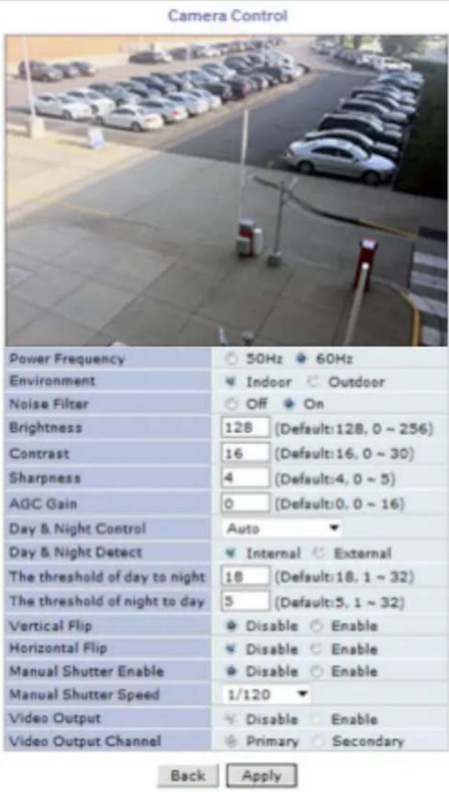
• Power Frequency: Select NTSC (60Hz) or PAL (50Hz) according to the region.
• Environment: Indoor or Outdoor
- Noise Filter: To reduce static on image
| Environment | IndoorOutdoor |
| Noise Filter | OffOn |
- Brightness: Select the brightness of image between 0 and 256.
-
Contrast: Select the contrast of image between 0 and 30.
-
Sharpness: select the sharpness of image between 0 and 5.
- Day & Night Control: If used, the image will be in Color mode during daytime and Black & White mode during night time.
| Day & Night Control Description | |
| Disable (No Image Conversion) | |
| Black & White Black & White mode | |
| Auto | Daytime: Color ModeNight time: Black & White mode |
• Day & Night Detect:
| Day & Night Detect Description | |
| Internal | Use Built-in Day & Night feature (Default) |
| External For use with cameras | having IR |
- The threshold of day to night: This is the point of transition from Day to Night mode. Select between 1 and 32, and lower the value the earlier the transition point.
- The threshold of night to day: This is the point of transition from night to day mode. Select between 1 and 32, and lower the value the earlier the transition point.
• Vertical Flip: this is to rotate the image 180° Vertically
• Horizontal Flip: this is to rotate the image 180° Horizontally - Manual Shutter Enable: If enabled, the shutter speed will be selected manually. If disabled, it is controlled automatically.
- Manual shutter Speed: available only when Manual Shutter is Enable Select the shutter speed of camera between 1/30 and 1/24000.
• Video Output: Video output (NTSC/PAL) is enabled.
After all the settings are done, click Apply button to save it. If Default button is clicked, all the fields return back to original value.
Motion Detection
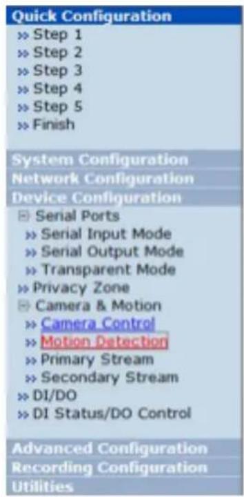
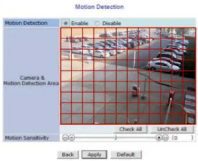
- Motion Detection: (this is only available in Primary Stream) If enabled, Motion Detection feature is activated and user can configure the areas where motion detection function will work. Click Check All button for whole scene to be active (grid will turn Green) then click on any box inside scene to take out that area from Motion Detection (box will turn Red) then click Apply to save
- Motion Sensitivity: Set the sensitivity of motion defined in Motion Detection Area. Select between -100 and 100. 100 is the most sensitive.
After all the settings are done, click Apply button to save it. If Default button is clicked, all the fields return back to original value.
DI / DO Control
Not Available on VTD-MV series
13. Advanced Configuration
There are two types of advanced service, one is Buffered Service and the other is Periodic Service. In Buffering Service, a series of images are continuously being stored in a buffer memory of the camera/server for a certain period of time. When the camera/server is triggered by an event or schedule, the images or alarm status just before and after the event/schedule are reported to you by email or buffered FTP services.
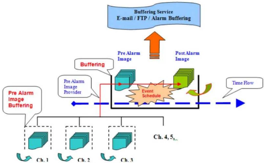
flowchart
graph TD
    A["Pre Alarm Image Buffering"] --> B["Ch. 1"]
    A --> C["Ch. 2"]
    A --> D["Ch. 3"]
    B --> E["Event Schedule"]
    C --> E
    D --> E
    E --> F["Time Flow"]
    G["Buffering Service\nE-mail / FTP / Alarm Buffering"] --> H["Pre Alarm Image"]
    H --> I["Pre Alarm Image Provider"]
    I --> J["Buffering"]
    J --> K["Post Alarm Image"]
    K --> L["Event Schedule"]
    L --> M["Time Flow"]
    N["Ch. 4, 5..."]
In Periodic Service, only the image, alarm/sensor status after an event/schedule is reported to you upon the server being triggered.

flowchart
graph TD
    A["Periodic Service FTP (Periodic) / Sensor Notification / Alarm Output"] --> B["Post Alarm Image"]
    B --> C["Event Schedule"]
    C --> D["Ch. 1"]
    C --> E["Ch. 2"]
    C --> F["Ch. 3"]
    D --> G["Time Flow"]
    E --> G
    F --> G
    G --> H["Feedback to Event Schedule"]
    H --> I["Ch. 4, 5"]
13.1. Advanced Services
Pre-Alarm buffer size and buffering speed can be defined here.
- Pre-Alarm Buffer Size: You can set the buffer size which will store the images before event. The unit is in frame, and each channel can be set with different values. The total number of frames for Pre-Alarm Buffer and Post-Alarm Buffer is limited to 10 frames.
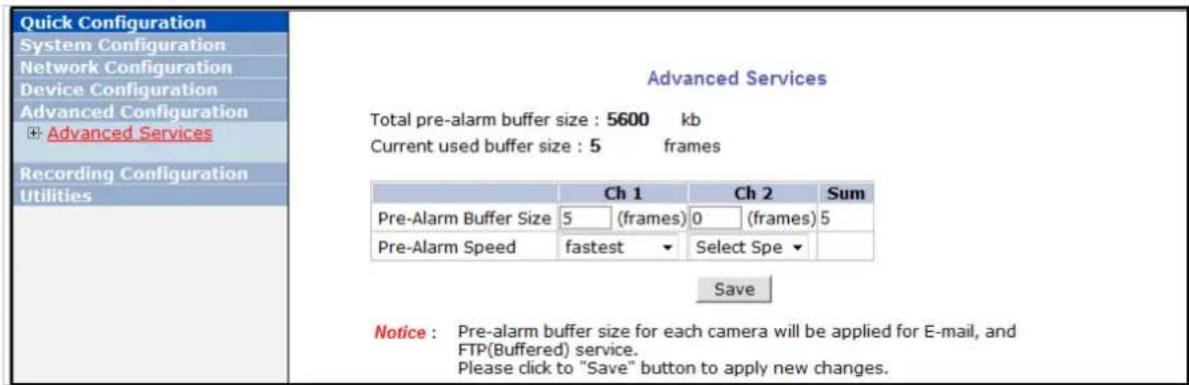
- Pre-Alarm Speed: You can set the buffering speed. If it's set to Fastest, the server will store images as fast as it can. Each cannel can be set with different values.
This configuration applies to E-mail and FTP (Buffered), and click Save button to apply changes.
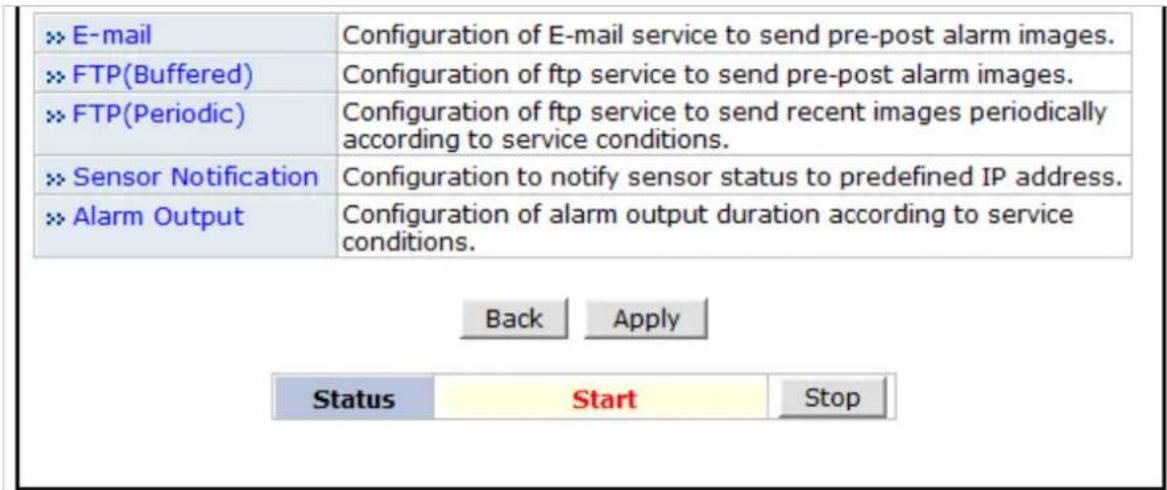
• E-mail: Set up Email Service configuration
- FTP (Buffered): Set up FTP (Buffered) Service configuration
- FTP (Periodic): Set up FTP (Periodic) Service configuration
13.1.1.E-mail Service Configuration
Email configuration is set up here for Alarm in case any event occurs.

flowchart
graph LR
    A["Advanced Configuration"] --> B["Advanced Configuration"]
    B --> C["Advanced Configuration"]
    C --> D["Advanced Configuration"]

    A -->|E-mail| E["E-mail"]
    A -->|FTP(Buffered)| F["FTP(Buffered)"]
    A -->|FTP(Periodic)| G["FTP(Periodic)"]
    A --> H["Sensor Notification"]
    A --> I["Alarm Output"]

    B -->|Camera 1| J["Camera 1"]
    B -->|Camera 2| K["Camera 2"]
    B -->|FTP(Buffered)| L["FTP(Buffered)"]
    B -->|FTP(Periodic)| M["FTP(Periodic)"]
    B --> N["Sensor Notification"]
    B --> O["Alarm Output"]

    C -->|Condition 1| P["Condition 1"]
    C -->|Condition 2| Q["Condition 2"]
    C -->|Condition 3| R["Condition 3"]
    C -->|Camera 2| S["Camera 2"]
    C -->|FTP(Buffered)| T["FTP(Buffered)"]
    C -->|FTP(Periodic)| U["FTP(Periodic)"]
    C --> V["Sensor Notification"]
    C --> W["Alarm Output"]
E-mail Service Configuration
Please click the below link to configure E-mail service for each camera.
Notice : This service is valid for M-JPEG only.
| Item | Description |
| Camera 1~2 | Select a channel to be configured for email notification |
| Service | Select Enable in order to use this service |
| SMTP server address | Enter SMTP server's address for sending email. |
| Authentication Login | Select Enable if SMTP server requires ID and password |
| User ID Enter User ID to log in to SMTP server | |
| Password Enter Password to log in to SMTP server | |
| Sender | Enter email address of the sender |
| 1st Recipient | Enter the email address of the first recipient |
| 2nd Recipient | Enter the email address of the second recipient |
| 3rd Recipient Enter the email address of the third recipient | |
Click Save button to apply the change. If you don't want to change, click Back button.
E-mail Service Setup for Each Channel
For each channel, the following items can be configured for email service: Condition, Post-Alarm Buffer Size, and Post-Alarm speed. The content of text message and display style of DI value can be configured as well.
E-mail Service Configuration at Camera 1
Please click below link to configure the service condition.
| » Condition 1 | [Not Used] |
| » Condition 2 | [Not Used] |
| » Condition 3 | [Not Used] |
Maximum 10 pre-post alarm images can be transmitted.
| Pre-Alarm Buffer Size | 0 (frames) | ×× Check video buffer | |
| Pre-Alarm Images | 0 | Post-Alarm Images | 0 |
| Pre-Alarm Speed | Select Speec | Post-Alarm Speed | Select Speec |
| Subject | Message From IP Device![0,0] | ||
?
| Message | Value Format | ||||||
| NONE | INT | HEX | BIN | IPA | EVT | ||
| 1 | |||||||
| 2 | |||||||
| 3 | |||||||
| 4 | |||||||
Back
Save
Item Description
| Condition 1 ~ Condition 3 | Select a condition for Email service to be activated. |
| Pre-Alarm Buffer Size | The Buffer size assigned for Pre-Alarm. |
| Check Video buffer | Click this link to go to Advanced Services for buffer setup. |
| Pre-Alarm Images | The number of image frames to store before Alarm |
| Post-Alarm Images | The number of image frames to store after Alarm |
| Pre-Alarm Speed | This field shows the speed of Pre-Alarm. Configuration can be done in Advances Services page. |
| Post-Alarm Speed | Select the speed of Post-Alarm.Fastestis the highest value. |
| Subject | Subject of the E-mail message to send. |
| 1 | Content of the first line in the email message. |
| 2 | Content of the second line in the email message. |
| 3 | Content of the third line in the email message. |
| 4 | Content of the fourth line in the email message |
| Value Format | Select the format for the Event or DI data to email.NONE: Don’t Send, INT: Decimal, HEX: Hexadecimal,BIN: Binary, IPA: IP Address, EVT: Name of Event |
After finishing setup, click Save button to apply. If you don't want to change, click Back button.
Condition, Schedule & Event Configuration

If you click on a Condition link, the Advanced Service windows is displayed as shown below. Alarm Service is activated only when the conditions in Advanced Services are met.
| Item | Description |
| Service This shows what service this condition is for. | |
| Module ID Module ID for current setup | |
| Camera ID | Channel ID for current setup |
| Enable / Disable | Select Enable to use Condition, otherwise select Disable. |
| Always | This Condition applies all the time. (Schedule or Event is not usable) |
| Schedule Only | Use Week, Time, and Date in Condition parameter. If none of the weekdays are checked, it is activated every day. |
| Event Only | It is activated only when any of the following events occurs. (Sensor, Motion Detection, Camera Connection, Server Booting) |
To save the setting, click Save button. If you want to cancel it, click Back.
13.1.2.FTP (Buffered) Service Configuration
FTP(Buffered) Service Configuration
Please click the below link to configure FTP(Buffered) service for each camera.
| » Camera 1 | » Camera 2 | |
| Service | ○ Enable ○ Disable | |
| Server Address | ||
| Base Directory Name | ||
| Base File Name | ||
| User ID | ||
| Password | ||
| FTP Control Port | | (Default:21, 0 ~ 65535) | |
| Date Description Mode | American Style ▼ | |
| Connection Mode | ○ Active ○ Passive | |
?
| Option | Directory Name | File Name |
| Server Name | ||
| Weekday | ||
| Year | ||
| Month | ||
| Day | ||
| Hour | ||
| Minute | ||
| Sec | ||
| Sequence | ||
| Camera Number |
Back
Save
Make Directory
Notice : • This service is valid for M-JPEG only.
- If the value of the FTP Control Port is 0, it will be set using by system configuration. It is usually same as port number 21.
• The following are values of Date Descrtion Mode.
American Style -> Feb28th2009
European Style -> 28thFeb2009
ISO Standard -> 20090228
| Item | Description |
| Camera 1 - Camera 2 | Select which channel to set up for FTP (Buffered). |
| Service | Select Enable to use the FTP (Buffered) service. Otherwise select Disable. |
| Server Address | FTP Server Address. |
| Base Directory Name | The directory in FTP server where the data will be uploaded.(You should make the directory in the FTP server before using the service.) |
| Base File Name | The base file name of the data to be uploaded in FTP server. |
| User ID Enter a User ID to log in to FTP server. | |
| Password Enter the Password for the user ID to log in to FTP server | |
| FTP Control Port | Port number for FTP server (Normally 21 is used) |
| Date Description Mode | Select Date Display Style: American, European or ISO Standard |
| Connection Mode | Select connection mode for FTP server |
| Server Name | If Directory Name is checked, new directory is created with server name.If File Name is checked, new file is created with server name. |
| Weekday | If Directory Name is checked, new directory name is created with weekday.If File Name is checked, new file name is created with weekday. |
| Year | If Directory Name is checked, new directory name is created with Year.If File Name is checked, new file name is created with Year. |
| Month | If Directory Name is checked, new directory name is created with month.If File Name is checked, new file name is created with month. |
| Day | If Directory Name is checked, new directory name is created with day.If File Name is checked, new file name is created with day. |
| Hour | If Directory Name is checked, new directory name is created with hour.If File Name is checked, new file name is created with hour. |
| Minute | If checked, new file name is created with minute. |
| Sec | If checked, new file name is created with second. |
| Sequence | If checked, new files are created starting from 0, with increment of 1. |
| Camera Number | If Directory Name is checked, new directory is created with camera number.If File Name is checked, new file is created with camera number. |
To create a directory with the options shown above, click Make Directory button. After finishing the configuration, click Save button to apply the change and continue to the next page. Clicking Back button will cancel the changes and go back to the previous page. (This service is available only in M-JPEG mode.)
FTP (Buffered) Service Configuration at Camera 1
FTP(Buffered) Service Configuration at Camera 1
Please click below link to configure the service condition.
| » Condition 1 | [M1][] |
| » Condition 2 | [Not Used] |
| » Condition 3 | [Not Used] |
Maximum 256 pre-post alarm images can be transmitted.
| Pre-Alarm Buffer Size | 5 (frames) | » Check video buffer | |||
| Pre-Alarm Images | 0 | frames | Post-Alarm Images | 0 | frames |
| Pre-Alarm Speed | fastest | Post-Alarm Speed | Select Speec | ||

Notice : If pre-alarm buffer size is not configured, pre-alarm is not served. Number of pre-alarm images must be less than pre-alarm buffer size.
| Item Description | |
| Condition 1 ~ Condition 3 | Select a condition for FTP (Buffered) service to be activated. Up to 3 conditions can be set. |
| Pre-Alarm Buffer Size | The Buffer size assigned for Pre-Alarm. |
| Check Video buffer | Click this link to go to Advanced Services for video buffer setup. |
| Pre-Alarm Images | The number of image frames to store before Alarm. |
| Post-Alarm Images | The number of image frames to store after Alarm. |
| Pre-Alarm Speed | This field shows the speed of Pre-Alarm. Configuration can be done in Advances Services page. |
| Post-Alarm Speed | Select the speed of Post-Alarm.Fastestis the highest value. |
After finishing setup, click Save button to apply. If you don't want to change, click Back button.
13.1.3.FTP (Periodic) Service Configuration
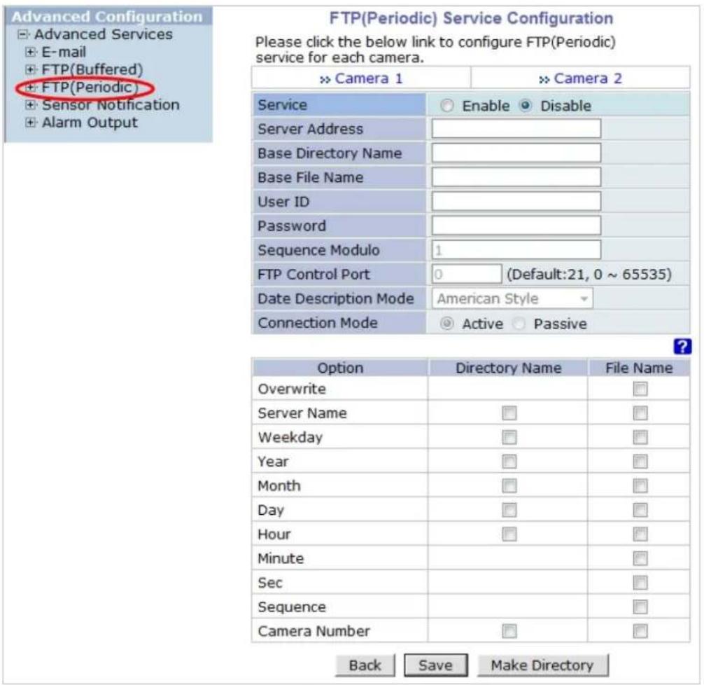
Notice : • This service is valid for M-JPEG only.
- If the value of the FTP Control Port is 0, it will be set using by system configuration. It is usually same as port number 21.
• The following are values of Date Descrtion Mode.
American Style -> Feb28th2009
European Style -> 28thFeb2009
ISO Standard -> 20090228
| Item Description | ||
| Camera 1 - Camera 2 | Select which channel to set up for FTP (Periodic) service | |
| Service | Select Enable to use the FTP (Periodic) service. Otherwise select Disable. | |
| Server Address FTP Server Address. | ||
| Base Directory Name | The directory in FTP server where the data will be uploaded.(You should make the directory in the FTP server before using the service.) | |
| Base File Name | The base file name of the data to be uploaded in FTP server. | |
| User ID | Enter a User ID to log in to FTP server. | |
| Password Enter the Password for the user ID to log in to FTP server | ||
| Sequence Modulo | Maximum number used in sequential file name | |
| FTP Control Port | Port number for FTP server (Normally 21 is used) | |
| Date Description Mode | Select Date Display Style: American, European or ISO Standard | |
| Connection Mode | Select connection mode for FTP server | |
| Overwrite | If checked, new file overwrites the existing file with the same name. | |
| Server Name | If Directory Name is checked, new directory is created with server name.If File Name is checked, new file is created with server name. | |
| Weekday | If Directory Name is checked, new directory name is created with weekday.If File Name is checked, new file name is created with weekday. | |
| Year | If Directory Name is checked, new directory name is created with year.If File Name is checked, new file name is created with year. | |
| Month | If Directory Name is checked, new directory name is created with month.If File Name is checked, new file name is created with month. | |
| Day | If Directory Name is checked, new directory name is created with day.If File Name is checked, new file name is created with day. | |
| Hour | If Directory Name is checked, new directory name is created with hour.If File Name is checked, new file name is created with hour. | |
| Minute | If checked, new file name is created with minute. | |
| Sec | If checked, new file name is created with second. | |
| Sequence | If checked, new files are created starting from 0, with increment of 1. | |
| Camera Number | If Directory Name is checked, new directory is created with camera number.If File Name is checked, new file is created with camera number. | |
To create a directory with the options shown above, click Make Directory button. After finishing the configuration, click Save button to apply the change and continue to the next page. Clicking Back button will cancel the changes and go back to the previous page. (This service is available only in M-JPEG mode.)
FTP (Periodic) Service Configuration for each channel
![Advanced Configuration ► Advanced Services ► E-mail ► FTP(Buffered) ► FTP(Periodic) ► Camera 1 ► Camera 2 ► Sensor Notification ► Alarm Output FTP(Periodic) Service Configuration at Camera1 Please click below link to configure the service condition. ► Condition 1 [Not Used] ► Condition 2 [Not Used] ► Condition 3 [Not Used] Alarm Speed Select Speed ▼ Back Save](/content/2026/06/1213747/images/947ed505b8fa70f23b607befc957f0b39b8ff3d94705a42b2c49069e5549a43f.jpg)
Notice : FTP interval is the time interval between each image upload service. If you put the number, the last numeric digit will be truncated to zero. For example, if you type 154 or 17, it becomes 150msec and 10msec. If the number is lower than 10, FTP interval becomes zero and FTP service is executed without any time interval.
| Item | Description |
| Condition 1 ~ Condition 3 | Select a condition for FTP (Periodic) service to be activated. Up to 3 conditions can be set respectively. |
| FTP interval (msec) | Select the speed of images to send in FTP(Periodic) service |
After finishing setup, click Save button to apply. If you don't want to change, click Back button.
14. Recording Configuration for Cameras with microSD card
Some versions of VITEK IP cameras will have a microSD card slots on the back.
Those models can record and playback video from the microSD card if installed. Vitek IP cameras can
Support cards up to a 32GB. (Only use quality class 10 microSD cards)
14.1. MicroSD Configuration
If a microSD card (SD card) is not present in the slot already, power down the VITEK IP camera before inserting an SD card. Make sure to turn the power on after inserting the SD card. Open a web browser, type in the IP address of the VITEK camera. Log in as Admin, Enter Recording Configuration menu, and then click on SD Configuration then click on SD Information, the card's format information will be displayed
SD Information
| File System | -None- |
| Total Disk Size | -None- |
| Free Disk Size | -None- |
| Usage | -None- |
| Oldest Image | -none- |
| Last Image | -none- |
Detail Stored Image Information
If entire SD information is showing "-NONE-" this means SD card is not formatted, in this case click
Note: Be sure to turn off the device before installing a SD card. Otherwise, the SD card may become defective. Always check the recommended type of SD card because non-conforming SD cards can cause abnormal behavior of the system.
back button followed by clicking SD Status & Format
SD Status & Format (Normal)
| SD | Status |
| 1st SD | Unformatted |

Notice : Be careful! The system could be broken. If you inserted the SD memory with the power on, turn the power off and on again to format. If you select a SD to format, you will be automatically guided to the format menu. Once SD format is completed, you need to reset system. Once format starts, recording stops automatically. After reset system, recording starts automatically.
Click on "1 ^st SD" and the following screen will be displayed
SD Format
Format Option
Check Bad Block
- Format Option
When you enable the "Check Bad Block" option, the Network Video System check the surface of the HDD for detecting bad blocks.
Do not run other tasks, until format is completed. If this option is enabled, the format time may be several hours depend on the size of the HDD.
Back
Partition and Format
Read format option on screen and then click Partition and Format a pop up screen will display asking if you want to do a "Partition and formatting" click OK to continue or Cancel to stop. After clicking OK the following screen will be displayed
SD Format Status
Partition
STEP 1

Format
STEP 3

Complete
STEP 4
Description
Formatting SD.

73.3%
Notice : Do not run other tasks, until format is completed. Once SD format is completed, you will be guided to Format Complete page, automatically.
Note: if program is terminated during the "Format" process SD Card might be damaged
After formatting is completed the following screen will be displayed
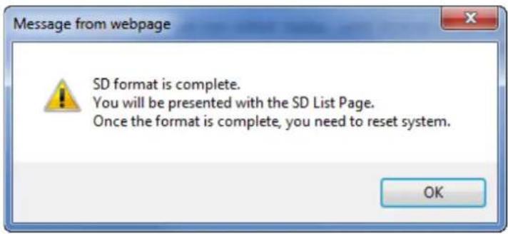
Click OK and you will be brought back to the "SD Status & Format screen" click on "Reboot" wait approximately 30 seconds and log back into the Admin screen. Open up "Recording Configuration" menu and click on "SD Configuration" then click on "SD Information" and the following screen will be displayed showing SD card info
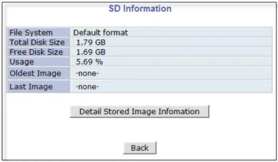
14.2. Recording Configuration with microSD card
Each camera has 2 streams (referred as Camera 1 / Camera 2 (see image below)) which can be configured for recording options in this section. Configuration items include motion detection recording, 24-hour continuous recording, event-driven recording, etc.
You can find out the list of streams (camera 1 / camera 2) with recording capability by clicking Recording Configuration on the left side of your screen. For example, you will see 2 streams (camera 1 / camera 2) from the list of VS Module ID (IP Devices).


Below is an example of configuring the motion detection-triggered recording. It starts by clicking Recording Configuration and clicking on Camera1, the following screen will be display.
![Recording Configuration (VS Module ID 0, Camera 1) » Display current recording configurations Please click below link for the recording configuration. » Condition 1 [Not Used] » Condition 2 [Not Used] » Condition 3 [Not Used] » Condition 4 [Not Used] 01 02 03 04 05 06 07 08 09 10 11 12 13 14 15 16 17 18 19 20 21 22 23 24 Sun Mon Tue Wed Thu Fri Sat 1 2 3 4 Alarm Sensor Motion Detection External Input Data Camera Connected Camera Disconnected Always Schedule Schedule and Event 1 2 3 4 1 2 3 4 Server Module ID 0 Camera Number 1 Camera Name Camera 1 Pre-Alarm Images 0 Post-Alarm Images 0 Pre-Alarm Speed fastest Post-Alarm Speed fastest Back Save Notice : It is recommended using MJPEG compression to use Pre-Alarm and Post Alarm service. If MPEG4 or H.264 video compression is selected, only I Frame will be recorded.](/content/2026/06/1213747/images/201ad0102192604dd0c4a1ffb4c2dfc26f7c818d812b884563267ce9ef07beac.jpg)
Select Condition 1 and the following window will be display.
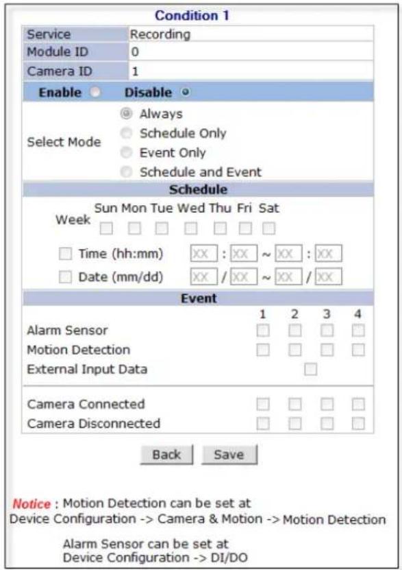
Enable / Disable
By clicking on Enable you will be able to select your mode (Always, Schedule only etc). in this example we will be selecting "Event Only".
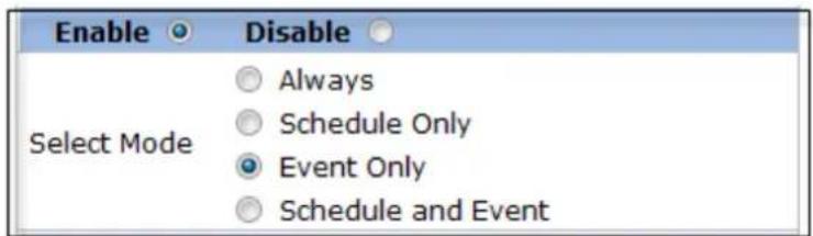
Schedule
Under Schedule you can select time and date for motion recording if left blank motion recording will be 24hrs, 7 days a week. In this example we will be leaving it blank (24/7).

Event
Under Event click Motion Detection (stream 1 / stream 2). Click on Save to finish.

15. Utilities
In Utilities part of the Admin menu, you can view the System Log file, Save Configuration, Reboot, Factory Default and System Update.
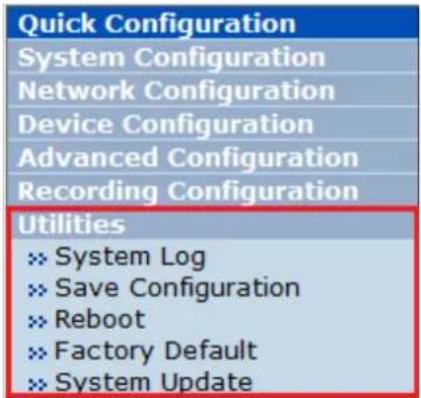
15.1. System Log
System log file provides you the information about when and who access' the contents of VITEK Cameras such as HTTP file or CGI programs. In each line, log data consists of date, time, category, IP address, user ID.
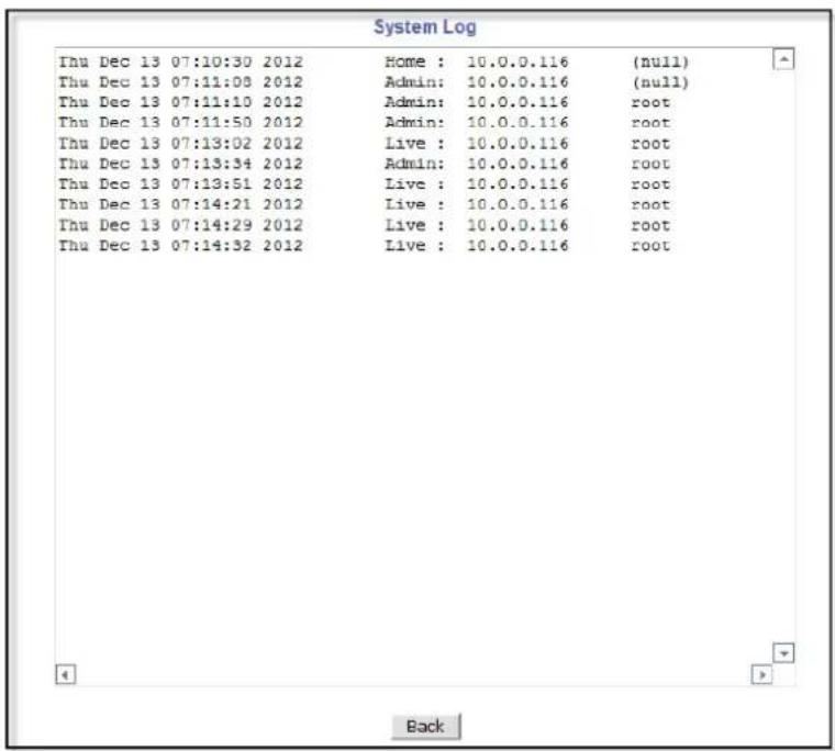
15.2. Save Configuration
VITEK cameras save the configurations after every step.
Save Configuration
- Changes to configuration will be saved automatically for this model.
Back
15.3. Reboot
It is recommended to reboot the system after making changes to the configuration. To reboot, click Reboot on Utilities menu. A screen will display to confirm a system reboot, click ok to continue.
Windows Internet Explorer will ask to close the webpage, click Yes.
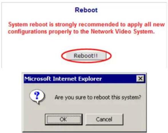
15.4. Factory Default
When required to restore the configuration of a Camera to factory default conditions, Network configuration is not affected by this action.
Click Factory Default on Utilities menu. A confirmation screen will be displayed as shown Click Factory Default button, otherwise click Back button to cancel it. The second confirmation screen will appear. Click OK button to restore the factory default condition right away. If you click Cancel, web browser will go back to the previous screen without any change made.

15.5. System Update
** Is Highly Recommended to Use the IP Installer Program for This Process **
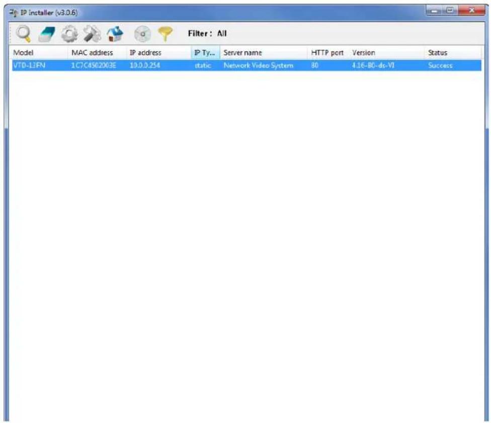
Once IP devices are searched and shown on the screen as functioning successfully, you can update the firmware of them using the "IP Installer" program. To do that, first check the firmware version of the device, which you can find on the IP Installer window.


In the above picture, the firmware version of this product is 4.14-01-ds while the latest firmware version available is 4.16-B0-ds-VI as you can see at Vitek's homepage
(http://www.vitekcctv.com/Downloads.asp). If you decide to update the firmware, first create a folder on your computer for the update firmware, than download the latest firmware to that folder.
Then select the IP device to be updated on IP Installer window, then click Update Firmware button from the toolbar. The following window will be displayed.
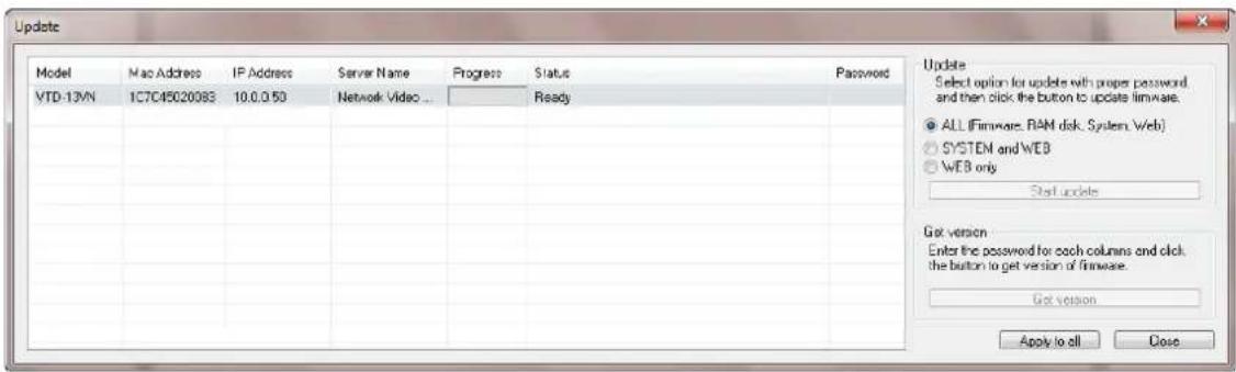
You may find the Password field is empty on the window shown above. If so, click the Password field of the IP device and enter the proper password for the device. You are not allowed to update the firmware if the correct password is not provided.
After the password is entered, the Start Update button will be enabled now. Click the button to see the following window for selecting the folder where the file has been saved. Highlight the folder than click OK.
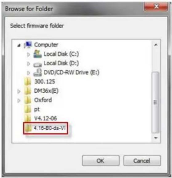
After clicking OK the following window will be displayed.

Note: Do not CLOSE window until completed, to avoid permanent damage to the camera.
16. ENVI Series Viewer
16.1. Introduction
ENVI Series Viewer is an ActiveX program for Internet Explorer web browser, which enable users to control video and audio functions of network video devices over the TCP/IP network. ENVI Series Viewer works with EN-V-R network video software, Vitek Network Video Servers, Network Video Recorders, and Network Cameras to show real-time live video images and enables users to control audio, Relay Output, and PTZ functions. (Supported cameras)
16.2. Key Features
• Displays live video streams transmitted from Vitek Cameras / Servers
- Plays audio transmitted from Vitek Cameras / Servers (supported cameras)
• Transmits audio from PC with ENVI Series Viewer to Vitek Camera / Servers
• Stores live video screen as image files
- Stores live video streams as video files
• Controls Relay Output of Vitek Cameras / Servers (supported cameras)
• PTZ Controls (supported cameras)
• Supports the group mode to see specific channels (for Network Video Recorders only)
• Displays live videos in full screen mode
• Supports Flexible Extra System
16.3. System Requirement for PC
For best quality and performance, your computer needs to meet the minimum requirement as below.
• OS: Microsoft Windows XP Pro, Windows 7
• CPU: Intel Pentium 4, 2 GHz (Dual-Core or faster is recommended)
- System RAM: 2GB
• Video Card: 256MB Ram, 1024x768 Resolution
• 100 Mbps Network Adaptor
17. Installing and Uninstalling
17.1. Installing ENVI Series Viewer
Connect to the Vitek Camera/Server using Internet Explorer, and click Live View on the main page. Then ENVI Series Viewer will be automatically downloaded and installed. If an Internet connection is not available, it's possible to manually install the program file in advance (from supplied CD) and connect to the Vitek Camera / Server later.
17.1.1. Installing on Web Browser
Click 'Live View' after access to Vitek® Server on Internet Explorer.

If you're using Windows XP Service Pack 2 or later, the Information message will show up as seen below. Click the Information message.
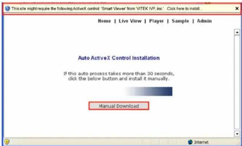
If the Information message doesn't come up due to the problems like network failure, you can start the manual installation as shown in the next section.
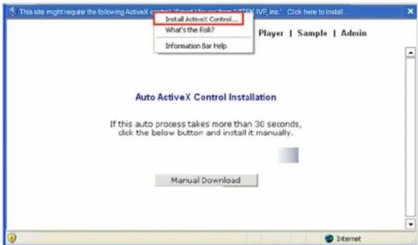
Click the Install ActiveX Control, and the pop-up window will be displayed as above. Click the Install button.
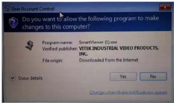
Click "YES" to allow program to run.
After the installation is successfully completed, ENVI Series Viewer window will be displayed.
Home | Live View | Admin

Model : VT-PTZ220NP, Firmware ver 4.16-B0-ds-VI
Homepage ver 4.16-B0_VT for Network Video System
17.1.2. Manual Installation
When an Internet connection is not available or having some difficulties, you can manually install from the supplied CD using ENVI Series Viewer program file. Execute the downloaded file, and you will see the ENVI Series Viewer Setup Wizard window as shown below. Click the Install button to start installing.
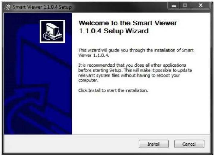
The following window will be displayed during the installation.

After installation is successfully completed, the following window will be displayed. Click the Finish button.
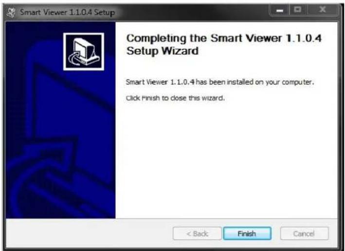
17.2. Uninstalling ENVI Series Viewer
There are two ways to uninstall ENVI Series Viewer program from your computer. Before uninstalling, close all the Internet Explorer windows.
17.2.1. Uninstalling with Program Menu
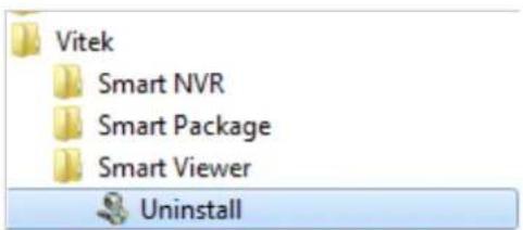
Click Uninstall and the following window will be shown. Click the Yes button.

If the uninstall is successful, the following window will be displayed. Click CLOSE to finish.
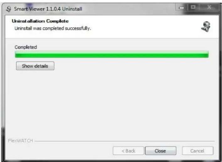
17.2.2. Uninstalling on Control Panel
Click Start button on the screen, then select the Control Panel.
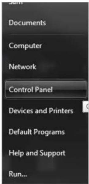
In the Control Panel window, double-click the Add or Remove Programs icon.
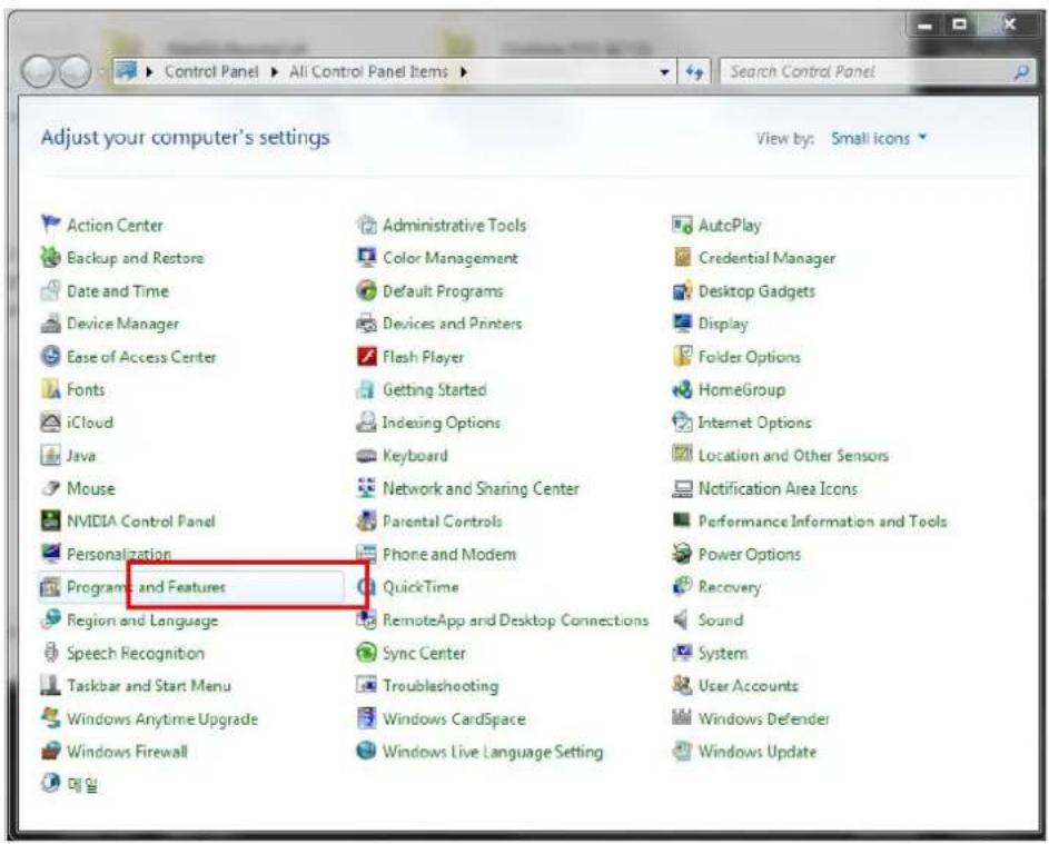
You will see the Currently installed programs list. Click ENVI Series / (Smart Viewer) button,
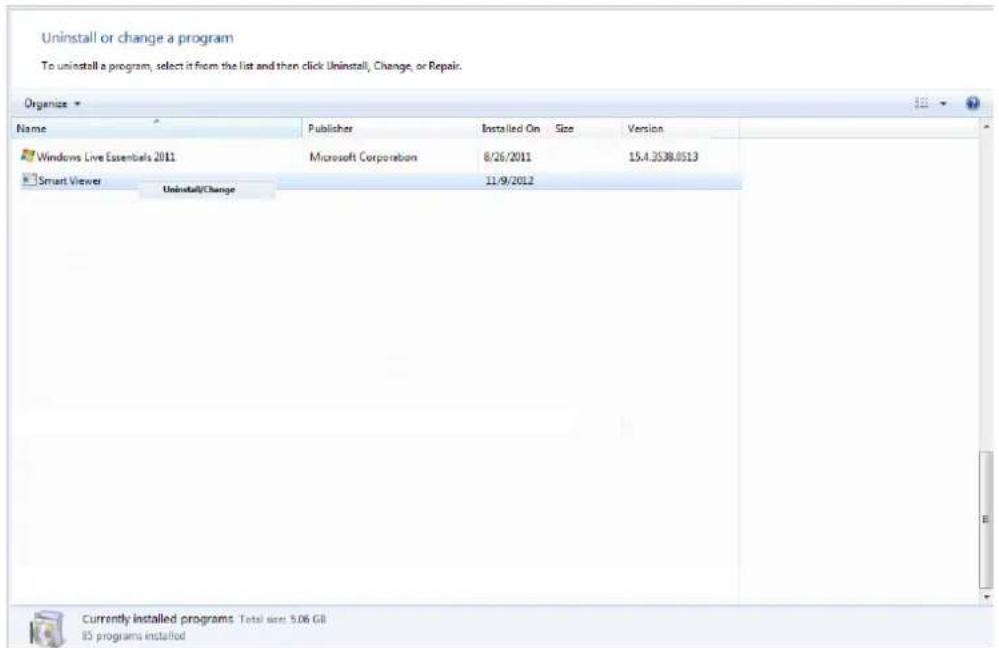
You will see the Uninstall or change a program list. Click ENVI Series / (Smart Viewer) button, and then right click Uninstall / Change button. Then, it will start uninstalling the program.
18. Starting ENVI Series Viewer
Once ENVI Series Viewer is installed in your computer, you can start it by connecting to the Vitek
Camera / Server using Internet Explorer and select Live View on the main menu.
The appearance of ENVI Series Viewer window varies depending on what type of Vitek Server is connected (Network Video Server, Network Camera, or Network Video Recorder).
• ENVI Series Viewer window for Network Video Server or Network Camera
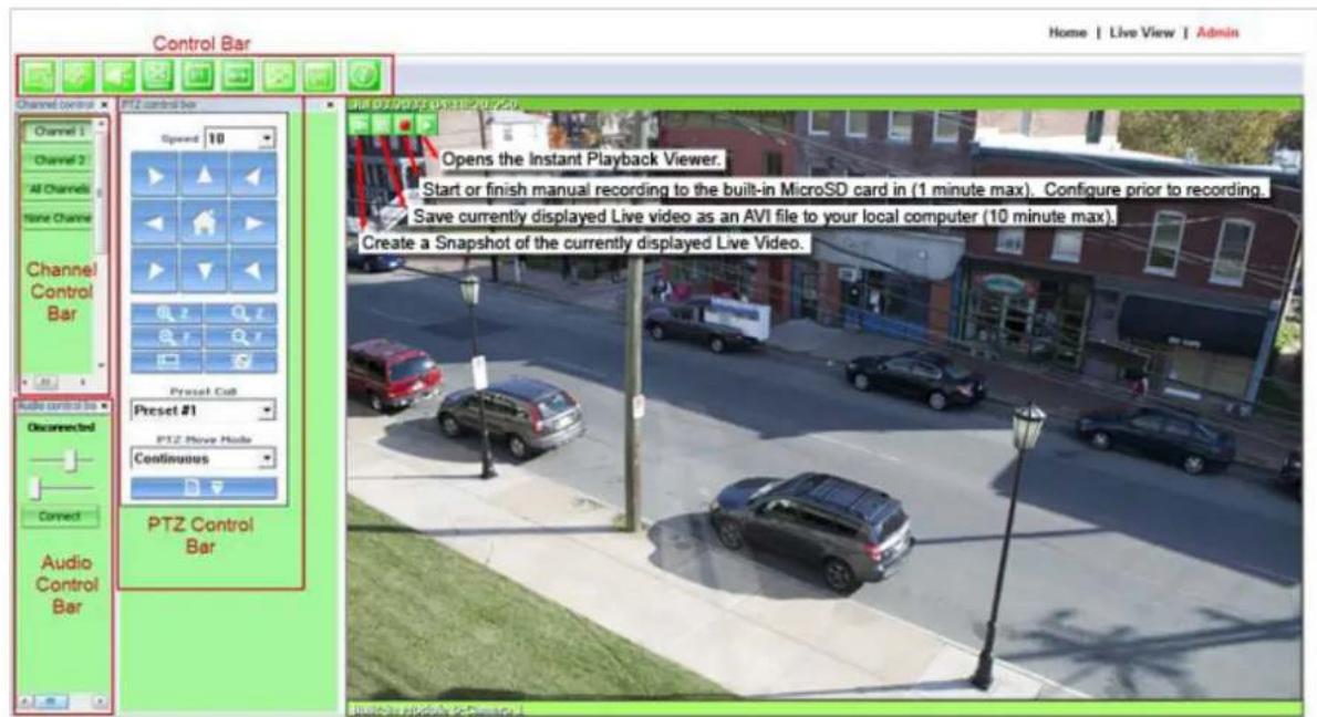
18.1. Control Bar


Displays and hides Channel control bar
Displays and hides PTZ control bar
Displays and hides Audio control bar
Display image by aspect ratio
Displays image normal screen
Display Enhancer on/off (uses more CPU)
Display Full / Normal screen
Displays image in original size

System Information Display
18.2. Channel Control Bar
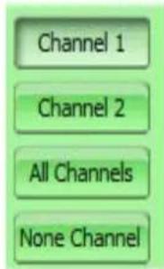
Displays or hides live view video from channel 1
Displays or hides live view video from channel 2
Displays or hides live view video from ALL channels
No Display
18.3. OSD Channels Buttons
18.3.1. Saving as Image File
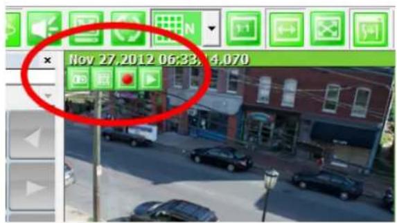

In ENVI Series Viewer, Live video currently displayed can be captured and saved as an image file either in JPEG or BMP format. Select the live view video you want saved, and click Snapshot button on OSD Channel Buttons. The following window will be displayed.

In this dialog box, you see the captured image to be saved. Enter the folder and file name, and click the Save button, then the image will be saved with the name you entered.

Note: If live view video is in MJPEG format, the image will be saved as a JPEG file. If the video is in MPEG-4 or H.264 format, it will be saved in BMP format.
18.3.2. Saving as Video File
In ENVI Series Viewer, Live video currently displayed can be captured and recorded as a video file in AVI format. Select a live view you want to save, and click RecAvi button on OSD Channel Buttons. Clicking it again will stop recording. Max duration is 10 minutes and recording will be stopped after 10 min if left un-clicked.
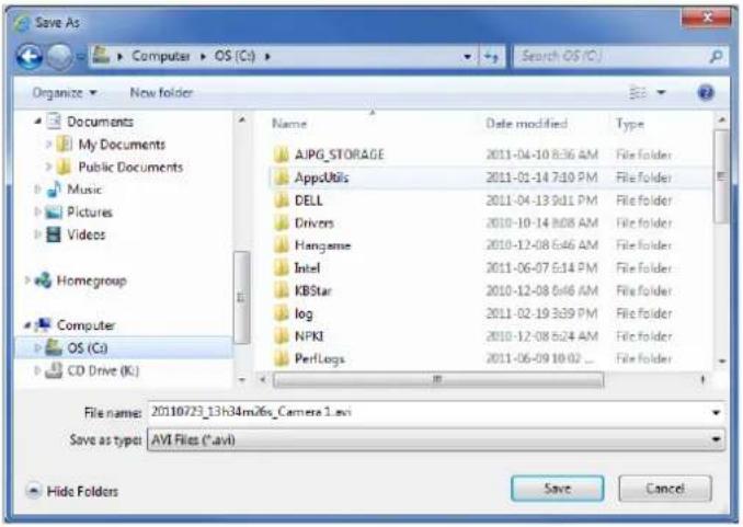
In video files recorded from M-JPEG format video, the time information file will be generated in SMI subtitle format, which puts time stamp every second. When you play back the recorded video, the time stamp will be displayed as a subtitle on the video screen as shown in the picture below. (upper left)

natural_image
Street scene with parked cars and storefronts, no visible text or symbolsNote: When you play back videos recorded from MPEG-4 or H.264, proper CODEC's may be required.
18.3.3. Manual Recording

To manual record from network cameras with built-in local storage (microSD), live video
can be recorded to the microSD card by clicking this button. The recorded video can be viewed by Instant Playback feature of OSD Channel Buttons or by running ENVI Series Player program. To finish, click the icon again. Max duration is 1 minute and recording will be stopped after 1 minute.
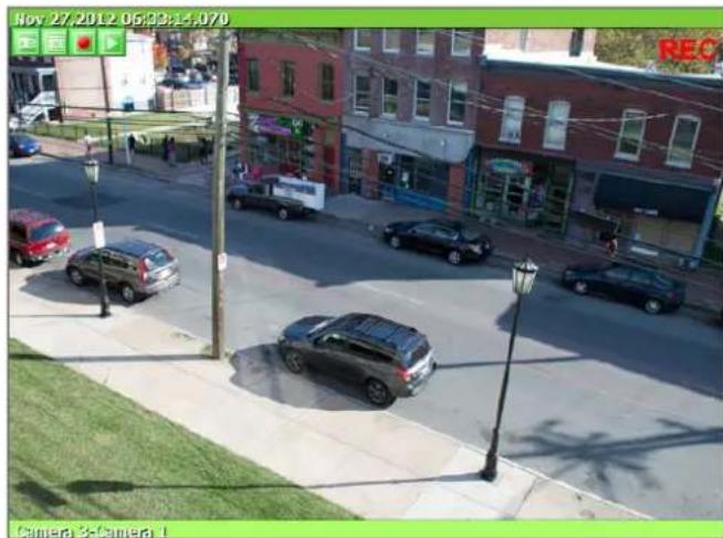
18.3.4. Instant Playback

For network cameras with local storage (microSD), Instant Playback is supported. Clicking tant Playback button from the OSD menu will open the window below.
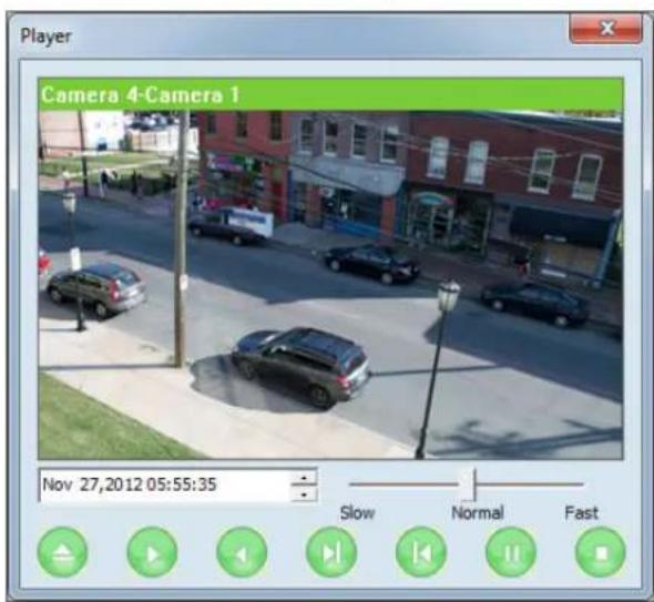
Instant playback will scan the video data up to 1 min before it was executed. And scanned data will be played automatically
| 1 05,2011 15:08:11 | Set the beginning of video data. Instant playback will scan 1 min after this. | ||
| Se the playback speed. | |||
| Begin searching data | |||
| Playback | |||
| Reverse playback. | |||
| 1 frame playback | |||
| 1 frame reverse playback | |||
| Pause | |||
| Stop | |||
18.4. Extended Features
When you click the right mouse button on the Live View Window, a pop-up menu will appear for extended features as shown below.

18.4.1. Pausing Live Video
Click the Pause button to stop and resume live view video.
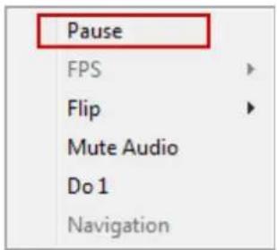
18.4.2. FPS Control
FPS (Frame per Second) can be controlled only in MJPEG mode. In MPEG4 and H.264 video mode, FPS control is not supported.

18.4.3.Flip Control
Flip Control: The horizontal view of the image can be changed using the (mirror) function. The vertical view of the image can be changed using the (flip) function.

19. EN-V-R: Introduction
This User's manual explains how to set up EN-V-R software in your PC. EN-V-R is the integrated system software for video security applications, which runs on Microsoft's Windows-based computers. Some of major features of EN-V-R are listed below.
- Provides main features of Live view, Playback, Record, Backup
• Event, motion, scheduled recording & conditional playback
• Motion-JPEG, MPEG-4, H.264 stream supported - Supports various vendors' IP devices (Multi Vendor Version only) for recording and retransmission of video, voice, and data
• Supports Megapixel cameras (up to 3M pixels) - Users can connect to EN-V-R via web browsers to access live video, Audio, and data, and search for video to play back
• Up to 128 channels supported for cameras
Note: A product-key is required for proper installation of EN-V-R program. You can still install EN-V-R in 10-working day trial mode if a product-key is not entered during installation. (Multivendor software only)

flowchart
graph TD
    A["Camera"] --> B["Server"]
    C["Camera"] --> D["Server"]
    E["Camera"] --> F["Server"]
    G["Camera"] --> H["Server"]
    I["Camera"] --> J["Server"]
    K["EN-V-R Server"] --> L["Analog"]
    L --> M["(HTTP port)"]
    M --> N["Computer"]
    M --> O["ENVI Viewer"]
    M --> P["ENVI Player"]
    M --> Q["ENVI Map"]
    M --> R["ENVI Alarm"]
20. Requirements for Installation
20.1. EN-V-R Versions
EN-V-R is supplied to customers in different versions for each appropriate application. Users will need to choose the right versions for their needs.
| Version Types | Register Channels | Time Restriction | Recording Channels | Retransmission Streams | Support Other vendors | Max Recoding Capacity |
| Evaluation | 128 | 10 days | 128 | 256 | Yes | 160 TB |
| Free | 16 | N/A | 16 | 64 | No | 160 TB |
| Multivendor | 9 | N/A | 9 | 36 | Yes | 160 TB |
| 16 | N/A | 16 | 64 | Yes | 160 TB | |
| 32 | N/A | 32 | 128 | Yes | 160 TB | |
| 64 | N/A | 64 | 256 | Yes | 160 TB | |
| 128 | N/A | 128 | 512 | Yes | 160 TB |
20.2. System Requirement for PC
For best quality and performance, your computer needs to meet the minimum requirement as below.
• Microsoft Windows XP Pro, Windows 7 Pro or higher, Video Card(256MB Ram, 1024x768 or higher)
| Compression | # of Channels | Resolution | Recommended CPU | Memory |
| H.264 | 16 Channels | D1 | Intel Core2Duo T5200 | 1.0GB |
| 720P | Intel Core2Duo E7550 | 1.5GB | ||
| 1080P | Intel Core i-5-2500S | 2.0GB | ||
| 32 channels | D1 | Intel Core2Duo E6700 | 1.0GB | |
| 720P | Intel Core i-5 750 | 2.0GB | ||
| 1080P | Intel Core i-7 970 | 4.0GB | ||
| 64 channels | D1 | Intel Core i-5 661 | 1.5GB | |
| 720P | Intel Xeon X5660 | 4.0GB | ||
| 1080P | Intel Xeon X5680 Dual CPU | 4.0GB | ||
| 128 channels | D1 | Intel Xeon X5507 Dual CPU | 4.0GB | |
| 720P | Intel Xeon X5670 Dual CPU | 6.0GB | ||
| 1080P | Intel Xeon E7-4850 Dual CPU | 6.0GB | ||
| Motion-JPEG | 16 Channels | D1 | Intel Core2Duo E6700 | 1.0GB |
| 720P | Intel Core i-5 460M | 1.5GB | ||
| 1080P | Intel Core i-5 -2500 | 3.0GB | ||
| 32 channels | D1 | Intel Core i-5 661 | 1.5GB | |
| 720P | Intel Core i-5 -2400S | 2.0GB | ||
| 1080P | Intel Xeon X5590 Dual CPU | 4.0GB | ||
| 64 channels | D1 | Intel Core i-5 -2500 | 3.0GB | |
| 720P | Intel Xeon X5550 Dual CPU | 4.0GB | ||
| 1080P | Intel Xeon E7-4850 Dual CPU | 6.0GB | ||
| 128 channels | D1 | Intel Xeon X5687 Dual CPU | 4.0GB | |
| 720P | Intel Xeon X5690 Dual CPU | 6.0GB | ||
| 1080P | Intel Xeon E7-4850 Dual CPU | 6.0GB |
Note: Above PC requirements are based on running EN-V-R program only. If other software needs to run along with EN-V-R at the same time, you may need additional performance level for your PC. It is recommended to check actual performance and disk capacity before selecting a PC for EN-V-R.
21. Installing EN-V-R

After downloading EN-V-R, double click EN-V-R Setup icon to start installation. The following window will be displayed on the screen. Before installing, check the version of the EN-V-R which is shown on the window.
You may encounter the following security warning. To continue installing the program, click Yes button.

Then select language for installation.
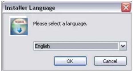
You will see the below window, then click Next button.

The default location for installation is C:\Program Files\Vitek. It is recommended to install in this folder,
but if you want to change it to another location, click Browse button to choose a proper path.
Now click Install button.
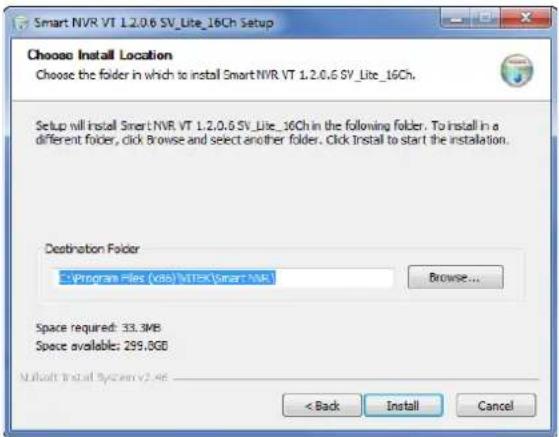
You will see the progress of copying install files to the hard drive as shown below, once is completed click on NEXT.

Click Finish to complete the Installation.

After installing EN-V-R program for the first time, it needs to be configured before use, so it automatically executes the configuration program, which is called EN-V-R Configurator.

Enter the proper Admin Password. The default password is root.
The following screen will be displayed, click OK to continue.

Now you will see EN-V-R Configurator window on the screen.

To use EN-V-R Configurator program, refer to Section 27. Starting EN-V-R Configurator on page 99.
If you need to uninstall EN-V-R, first you need to make sure EN-V-R program is not running on your computer by checking the system icon. As you see on the following picture, you can easily find out if EN-V-R service running.
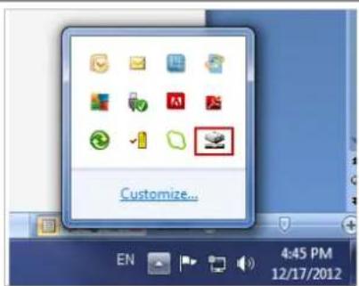
If EN-V-R is not running, you can go ahead to the next section of uninstalling the program. If EN-V-R is active, place the mouse pointer on the EN-V-R icon, and click the right mouse button. You'll see the pop-up menu. Select Exit.
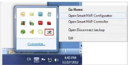
Then the EN-V-R icon disappears, and you know that EN-V-R is no longer running on your computer. Now you're ready to start uninstalling.
22.2. Executing Uninstaller
To start uninstalling, click Start > All Programs > Vitek> EN-V-R> Uninstall.

When the following window appears, click YES button.
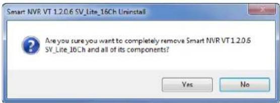
The progress of uninstalling is displayed.
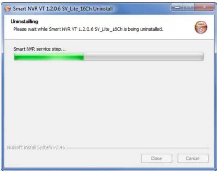
After all the install files are deleted, the following window will be displayed. Click OK button on the following window to complete the uninstalling.

23. Components of EN-V-R Program
EN-V-R consists of three programs, (EN-V-R Service, EN-V-R Configurator, and EN-V-R Controller).
23.1. EN-V-R Configurator
EN-V-R Configurator is used to set up various parameters and conditions of EN-V-R Service. Users can register, modify, and delete IP devices and users with this program. It also provides configuring tools for recording, alarm, event, and other functions.
23.2. EN-V-R Service
EN-V-R program is a Windows service and runs in a background mode, which means that it is not shown on the Windows desktop. EN-V-R receives video, audio, alarm, even data from IP devices over the network, and then it can record the data on the hard drive or retransmit to users. Starting, terminating and restarting of EN-V-R program can be done by using EN-V-R Configuration or EN-V-R Controller.
23.3. EN-V-R Controller
EN-V-R Controller program is used to start or stop the EN-V-R service.
23.4. EN-V-R System Tray Menu
After you finish installing EN-V-R, you will find the EN-V-R icon on the system tray, which is located right, bottom part of the Windows desktop.
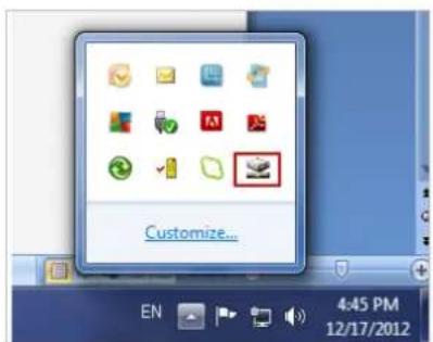
Move the cursor over the icon, and right click. The following pop-up menu will show. You can open EN-V-R Configurator or EN-V-R Controller program from this menu, or you can go to the Home page of the EN-V-R program for live view or playback.
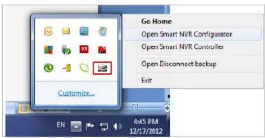
24. Starting EN-V-R Configurator
EN-V-R Configurator starts automatically right after installation is completed; you may also click the EN-V-R icon on the Windows desktop.
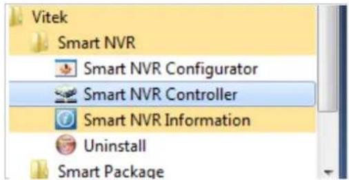
If EN-V-R program is already running in background, you may also select the EN-V-R icon on the system tray by clicking right button of the mouse.
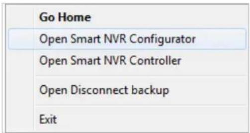
You may encounter the security window as below. Click Yes button to continue.
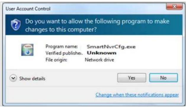
Once EN-V-R program starts, a log-in window will be displayed as below. Type in the proper admin password and click the OK button. The default admin / password is root.

Now EN-V-R Configurator window will be displayed.
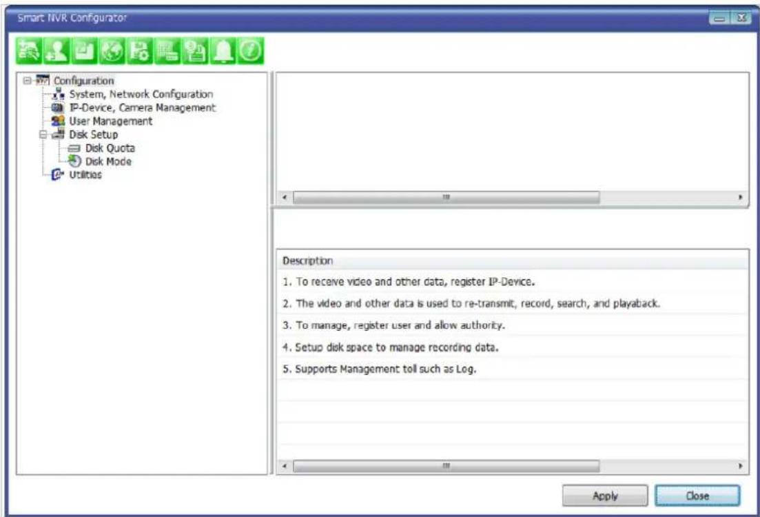
25. Quick Start Guide
EN-V-R is full-functioning Network Video Recorder software that runs on your PC. When started for the first time after EN-V-R is installed, there is no IP devices connected.
To add a camera to the EN-V-R you must register the camera first. Then EN-V-R knows what IP devices they are, how to connect to them, and how to use them. That way, you will be able to control EN-V-R for recording, live viewing, etc.
25.1. EN-V-R Configurator User Interface
The following picture shows the main window of EN-V-R Configurator program.
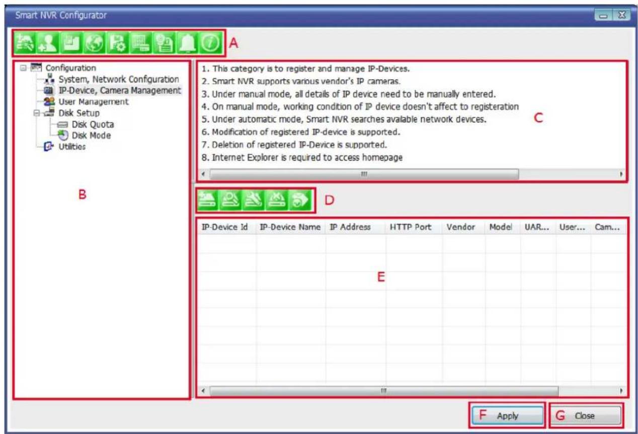
| Items Descriptions | ||
| A | Main Toolbar | Frequently-used menu items are shown on this toolbar. |
| B | Configuration Menu tree | Configurable categories are shown as a menu tree style. |
| C | Configuration Menu Description | Descriptions and usages of the selected category are displayed. |
| D | Sub-Menu Toolbar | Menu items for the selected category are shown.(Note: This toolbar is displayed only when any top menu item is selected from the menu tree.) |
| E | Device List | IP cameras Information |
| F | Apply Button | Click this button to apply the changed values. |
25.2. Searching for IP Devices
Click the first button on the Main Toolbar.
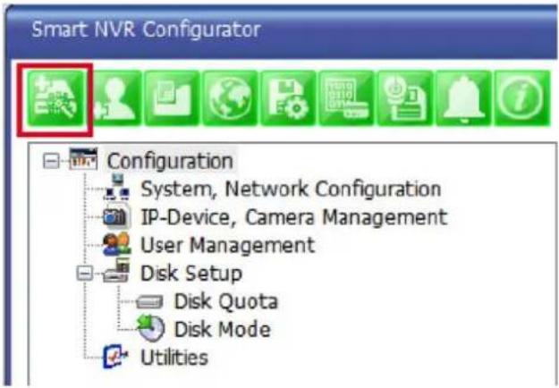
You are now given a choice to register the IP devices by "search and register or manually". To make it easy, choose Search and register IP-Device in this stage, and click Next button.
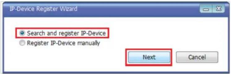
On the following window, click Scan button.

The searching for IP devices is started. As the detected IP devices are being listed. Wait until searching is finished. If you click Cancel button in the middle of searching, the EN-V-R will retain only the IP devices found until that moment.

25.3. Registering IP Devices
After scanning is finished, you have a list of IP devices found on your network. Next step is registering them. Double click the IP device you want to register or you may highlight it and then click Register button. In this example, the first one is chosen to register.
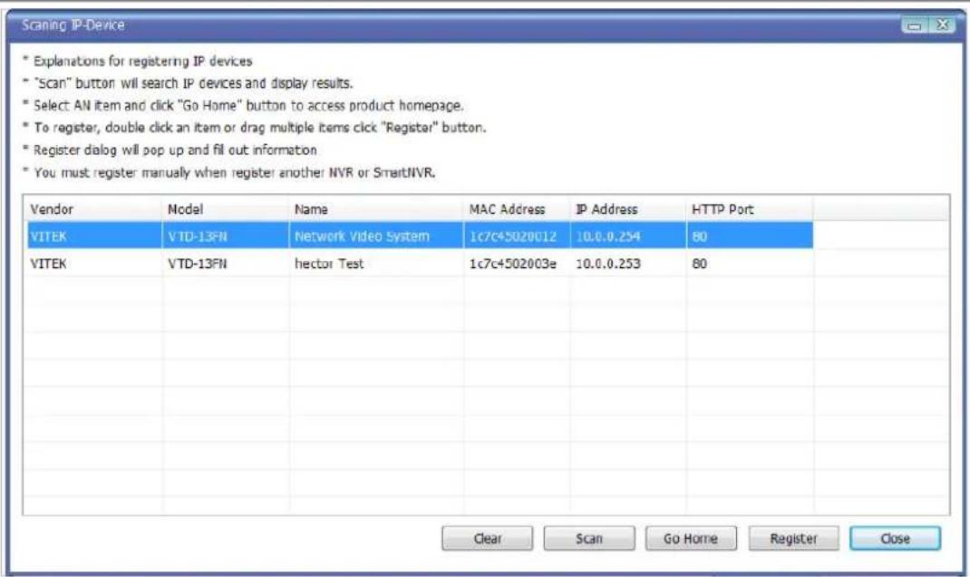
The next window shows up and it's for entering the network parameters and camera resolutions of the IP device you've chosen. You may need to enter the Login ID and Password here. Click Save to finish registering it.
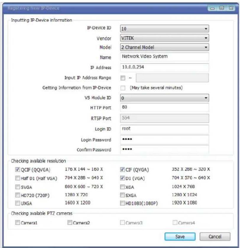
Click on Save after configuring IP device (camera)
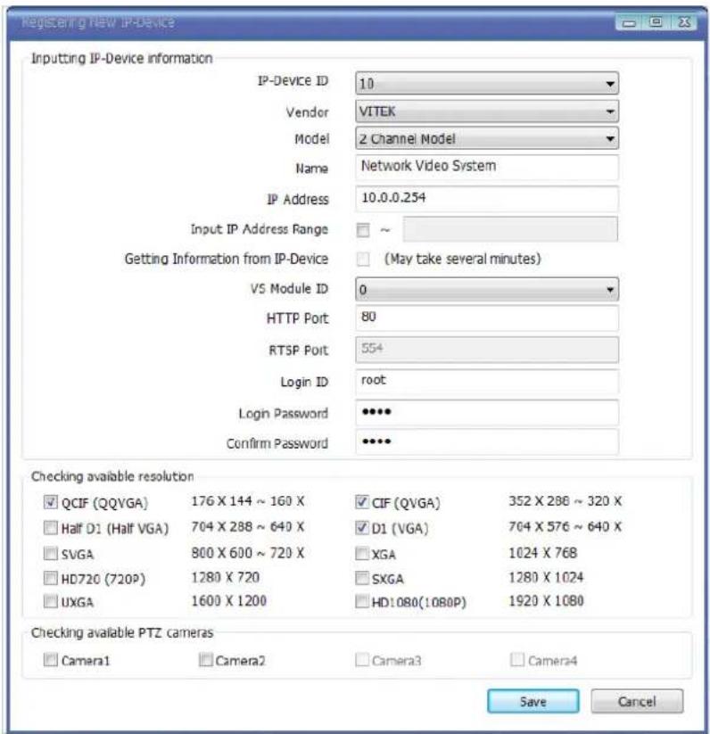
Click Apply after registering one or more IP devices (cameras). The image below represents the configurator with multiple IP devices registered.
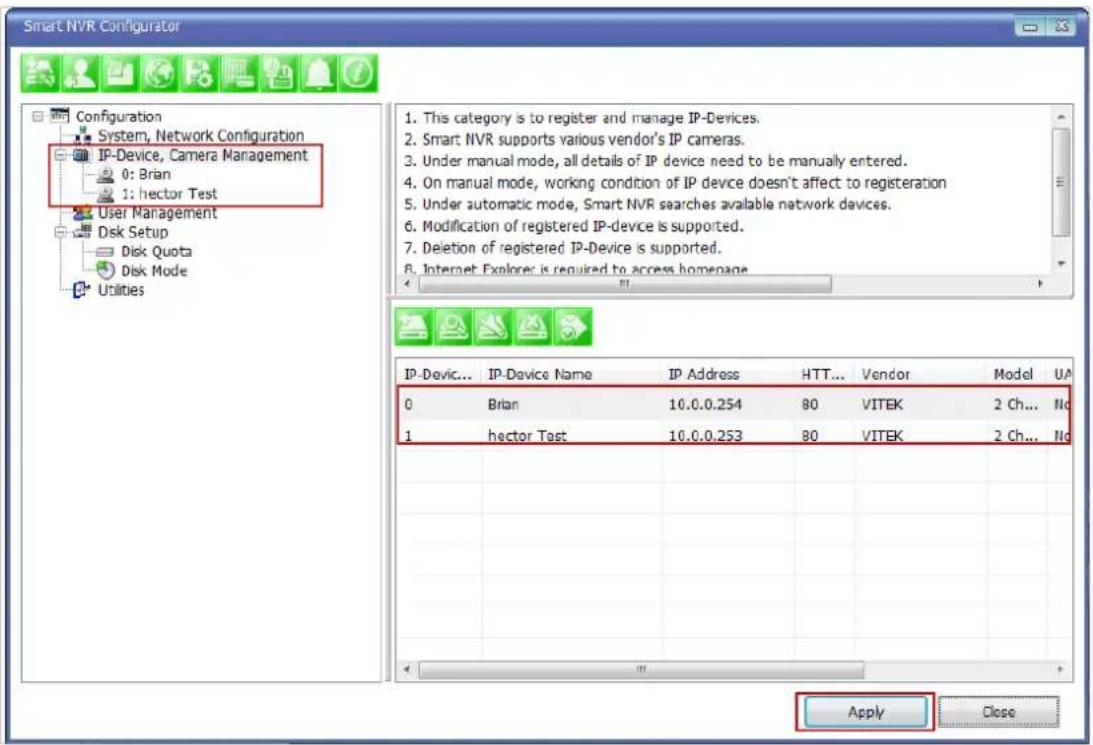
After clicking Apply, the program will ask you to confirm it. Then click OK

EN-V-R service is being stopped momentarily, and then it will start running again.
25.4. Viewing Live Video
Once the network and cameras are set up, it is necessary to check if EN-V-R is functioning by viewing the live video from those devices.
To view the EN-V-R home page, click the Go NVR Home button on the main toolbar.

natural_image
Green square icon set with icons representing information, tools, and a globe (no text or symbols)Below is an image of the EN-V-R home page.
Home | Live View | Player

Click Live View on top right part of the window to see the live video from registered IP devices (cameras)

If this is the first time you are using Vitek Live View feature, the web browser may ask you to allow installing of an ActiveX program. Click Install to continue.
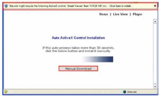
In some cases there is no response from the web browser, you may need to install the ActiveX manually by clicking Manual Download.
When you see the following security warning, click Install.
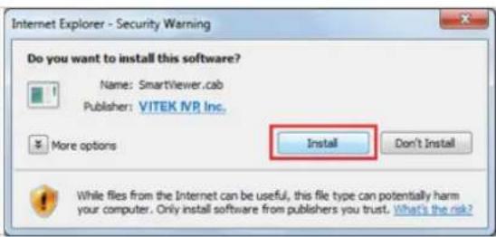
25.5. Recording Video
The essential feature of EN-V-R is recording the video from IP devices.
Before starting the recording, it is required to prepare the hard drive of your PC where EN-V-R program is running.
Click Disk Quota on the Menu tree.

The hard drive will be ready to start recording video after the progress window is done counting drives. It shows the target drive (s), total capacity, available size and quota for recording.
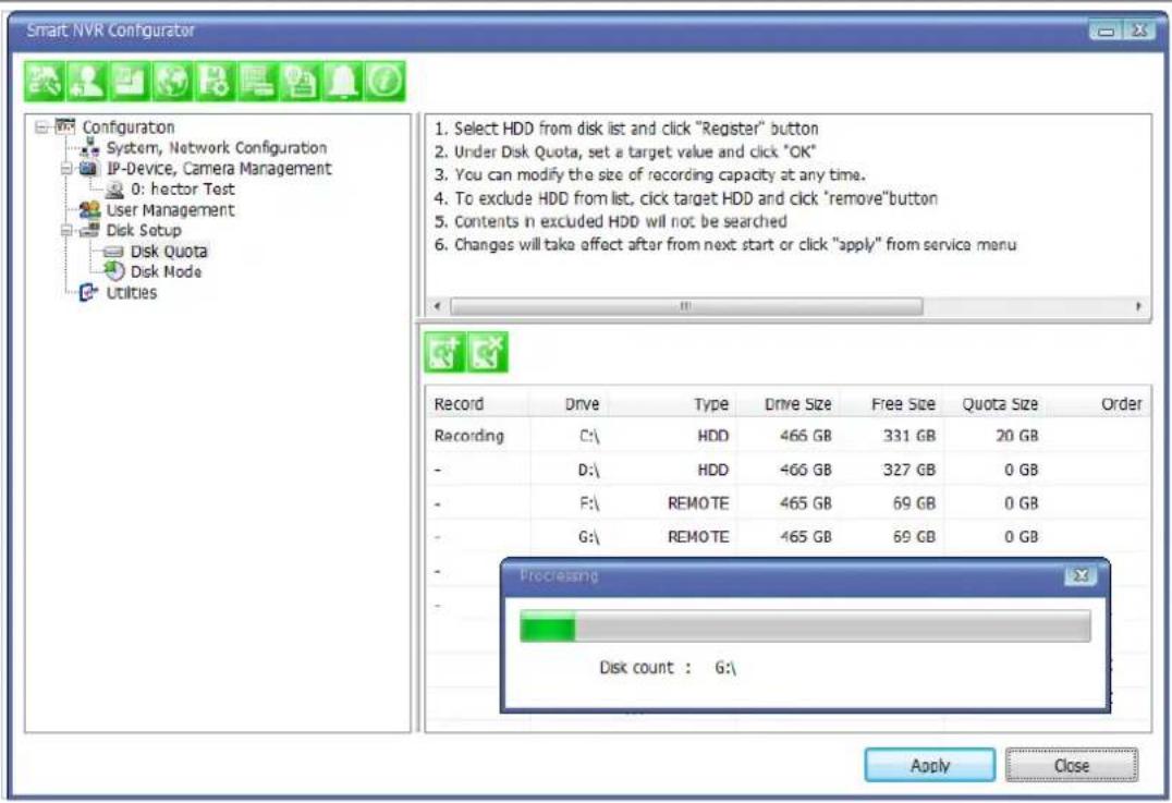
You are able to change the setting by highlighting the drive then clicking the first icon of the sub-menu Toolbar.
Use HDD (to use this HDD for recording)
Possible Maximum Quota (the available of free space on your HDD)
Possible Minimum Quota (the minimum amount required)
Set Quota (desired amount of HDD to be use for recording)
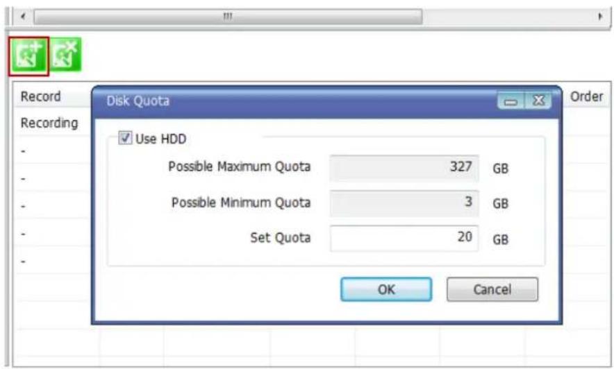
To set up the recording feature, select an IP device from the Menu tree on the left pane. The device information will be shown on the right pane. Click the button for recording configuration on the sub-menu Toolbar as shown below.
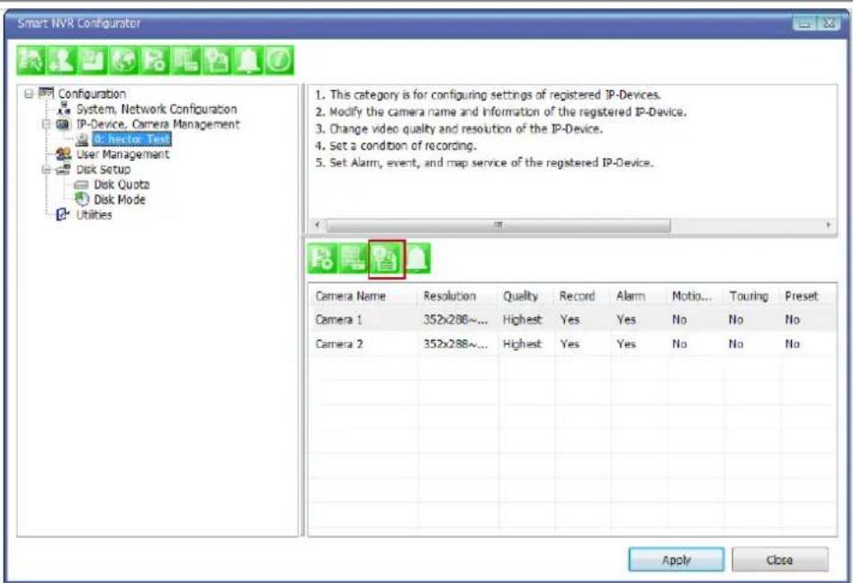
Now you will see Configure Recording Condition window as below.
![Configure Recording Condition 1. Select camera to configure condition 2. You can select to multi camera 3. Select condition to configure record condition 4. Configure detail schedule and event 5. Click Apply to camera button to apply condition 6. Change record service Pre, Post images 7. Click Apply to camera button to save changed condition Camera 1(Connection established) Recording Service Enable Recording Service Disable Recording Service Pre Alarm Images 0 Pre Alarm Speed fastest POST Alarm Images 0 POST Alarm Speed fastest Configure Recording Condition Input Condition Use this condition Do not use this condition Condition Mode Always Recording Recording by schedule only Recording by event only Recording by schedule and event Schedule Day of week Sun Mon Tue Wed Thu Fri Sat Time 12/31/1969 ~ 12/31/1969 Date 12/31/1969 ~ 12/31/1969 Event Alarm Sensor 1 2 3 4 Motion Detection External Input Data Condition list Apply to condition Camera Name Con... Condition Name Camera 1 1 [M1] Camera 1 2 - Apply to camera Camera list Select Multi Camera IP-Device Id IP-Device Name Camera Name Recording Condition 1 Condition 2 Condition 3 Condtic Camera 1 hector Test Camera 1 Enable [M1] - - - Camera 2 Camera 3 Camera 4 Unselect All OK Cancel](/content/2026/06/1213747/images/a2f8b870ac700194ed21cf538054e7a3515cca821ccc2dfd6e06622c120fabb3.jpg)
The recording feature is already enabled and recording conditions are configured in default settings. In the example shown above, you can see that Camera 1 of Device 0 will record video only when motion is
detected. Click OK to use this Recording Conditioned.
To change recording condition high light camera 1 under condition list (A)
Select the type of Recording under Condition Mode (B)
If schedule recording is enabled, the schedule section will be available to configure (C)
If Event is selected the event section will be available to configure (D)
After conditions are selected click Apply to condition (E)
After apply to condition click Apply to camera (F)
Click OK when done.
![Configure Recording Condition 1. Select camera to configure condition 2. You can select to multi camera 3. Select condition to configure record condition 4. Configure detail schedule and event 5. Click Apply to camera button to apply condition 6. Change record service Pre, Post images 7. Click Apply to camera button to save changed condition Camera 1(Connection established) Recording Service Enable Recording Service Disable Recording Service Pre Alarm Images 0 Pre Alarm Speed fastest POST Alarm Images 0 POST Alarm Speed fastest Configure Recording Condition Input Condition Use this condition Do not use this condition Condition Mode Always Recording Recording by schedule only B Recording by event only Recording by schedule and event Schedule Day of week Sun Mon Tue Wed Thu Fri Sat Time C AM 8:00 ~ PM 5:00 Date 12/18 ~ 12/18 Event Alarm Sensor 1 2 3 4 D Motion Detection ✓ ✓ ✓ ✓ ✓ ✓ ✓ ✓ ✓ ✓ ✓ ✓ ✓ ✓ ✓ ✓ ✓ ✓ ✓ ✓ ✓ ✓ ✓ ✓ ✓ ✓ ✓ ✓ ✓ ✓ ✓ ✓ ✓ ✓ ✓ ✓ ✓ ✓ ✓ ✓ ✓ ✓ ✓ ✓ ✓ ✓ ✓ ✓ ✓ ✓ ✓ ✓ ✓ ✓ ✓ ✓ ✓ ✓ ✓ ✓ ✓ ✓ ✓ ✓ ✓ ✓ ✓ ✓ ✓ ✓ ✓ ✓ ✓ ✓ ✓ ✓ ✓ ✓ ✓ ✓ ✓ ✓ ✓ ✓ ✓ ✓ ✓ ✓ ✓ ✓ ✓ ✓ ✓ ✓ ✓ ✓ ✓ ✓ ✓ ✓ Condition list Apply to condition Camera Name Con... Condition Name Camera 1 1 [Mon, Tue, Wed, Thu, Fri][08:00... Camera 1 A 2 - Camera 1 Apply to camera Camera list Select Multi Camera IP-Device Id IP-Device Name Camera Name Recording Condition 1 Condition 2 Condition 3 Condition Camera 1 Brian Camera 1 Enable [Mon, Tue... - - - - Camera 2 Camera 3 Camera 4 Unselect AI OK Cancel](/content/2026/06/1213747/images/df919ffa9981f3f0ef1936e53b39184405fa3a63129a12da57360942557102b8.jpg)
Now that the configuration is done, you need to start the EN-V-R service program. Select Start > All Programs > Vitek>smart NVR>Smart NVR controller.
You will find the EN-V-R icon on the system tray, which is located right, bottom part of the Windows desktop.

Move the cursor over the icon, and right click. The following pop-up menu will show. You can open EN-V-R Configurator or EN-V-R Controller program from this menu, or you can go to the Home page of the EN-V-R program for live view or playback.
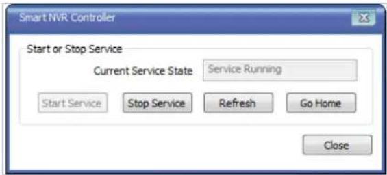
You can find out from this window that the service is running at that moment. If not, click Start Service button to run. Once EN-V-R service is started, the video sent from the configured camera will be recorded according to the recording condition.
26. ENVI Smart Player
26.1. Introduction
Smart Player is and ActiveX program for Internet Explorer Web browser, which enables users to search and play back recorded video in Network Video Servers and other devices with built-in recording capabilities. The Searching and playback of video is refined by condition, schedule, and event.
Smart Player can be run in SmartNVR network video software for PC and network cameras equipped with microSD card as well as standalone NVR (Network Video Recorder) devices.
26.2. Key Features
• Transforming recorded video into AVI, FJP&IDX, formats
• Supports Printing of video
- Playing Audio from recorded video
• Group Searching from recorded video
• Supports Full Screen Mode
26.3. System Requirement for PC
For best quality and performance, your computer needs to meet the minimum requirement.
• OS: Microsoft Windows XP Pro, Windows 7 Pro, Windows 8 PC
• CPU: Intel Pentium 4, 2 GHz (Dual-Core or faster is recommended)
- System RAM: 2GB
• Video Card: 256MB Ram, 1024x768 Resolution
• 100 Mbps Network Adaptor
27. Installing and Uninstalling
27.1. Installing Smart Player
Connect to the Vitek Camera / Server / NVR on Internet Explorer, and click Player on the main page.

If you're using Windows XP Service Pack 2 or later, it may asked you to install ActiveX click the massage bar than click on the Install ActiveX control...
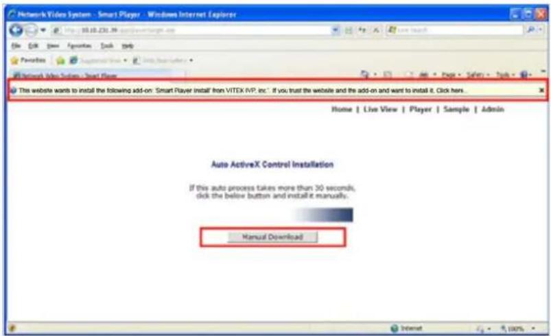
After the installation is successfully completed, Smart Player window will be displayed.
27.1.1. Manual Installation
When an Internet connection is not available or having some difficulties, you can manually download and install the Smart Player program file prior to setup, visit http://www.vitekcctv.com/Downloads.asp. You may also install from the provided CD. Execute the downloaded file, and you will see the Smart Player Setup Wizard window.
Click Run to start installing.

The following window will appear. Click Next.
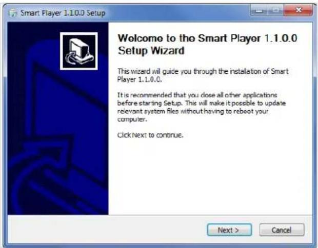
The following window will be displayed. Click Install

After installation is successfully completed, the following window will be displayed. Click Finish.
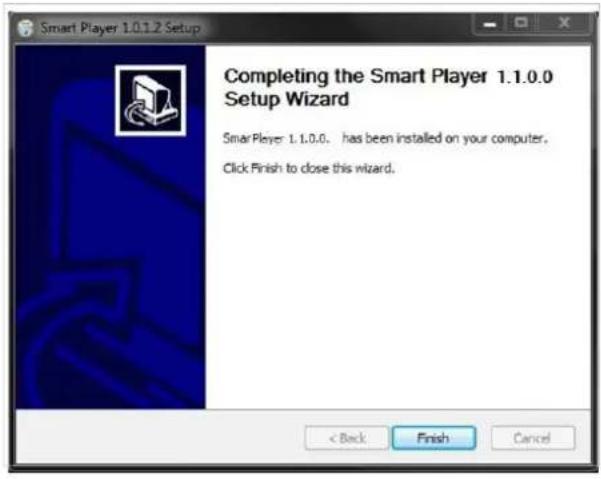
27.2. Uninstalling Smart Player
Before uninstalling, close all the Internet Explorer windows.
27.2.1. Uninstalling on Program Menu

Click Uninstall and the following window will be shown. Click the Yes button.

Live View & Play Back
To live view and play back your cameras, go to Start menu, All Programs, Vitek Folder, Click on Smart NVR Controller, as shown below.

Look for icon on right side of taskbar as shown below (windows XP and windows 8 might show it different). Right click icon.

The following window will display. Click on Open Smart NVR Controller.
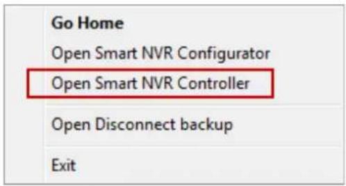
Click on Start Service to run the program.
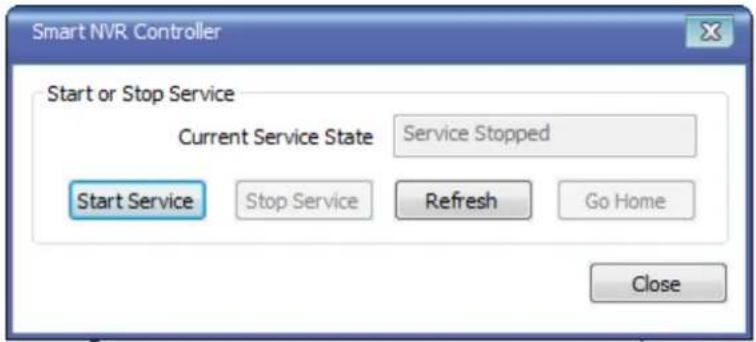
Click on Go Home to view Smart Player Home Page

Click on Live View
Home | Live View | Player

The following screen will be display were you can configure your live view.

Server Control Bar
Allows you to view cameras / servers that are registered in the system. Toggle On/Off


Group Control Bar

In order to view video, cameras must be assigned to a group, in this section you create groups with cameras you want to view.
Create Group
In order to create a group in Group Control Bar, right click on Group, another window will appear then select New.
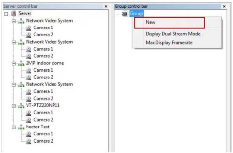
The following window will be displayed. Type in the group name, check "Circulation" to allow sequencing, input dwell time for "Circulation" and click OK.

A new group with the assigned name will be created as shown below.
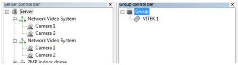
To add cameras to the new group, drag from server control bar and drop on newly created group. You can create multiple groups and add multiple cameras in each group.

flowchart
graph TD
    A["Server"] --> B["Network Video System"]
    B --> C["Camera 1"]
    B --> D["Camera 2"]
    A --> E["Network Video System"]
    E --> F["Camera 1"]
    E --> G["Camera 2"]
    H["Group control bar"] --> I["Group"]
    I --> J["VITEK 1"]
    J --> K["Network Video System-Camera 1"]
PTZ control Bar

In this section you will be able to control PTZ's connected to the system.
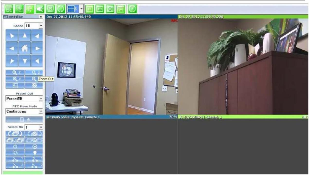
Audio Control Bar

Controls Speaker and Mic volume.
When audio is available click on Connect and adjust speaker and mic levels, when done click Disconnect.

Full/Normal Screen

Select full screen as seen below, to return to normal press Esc on your keyboard.
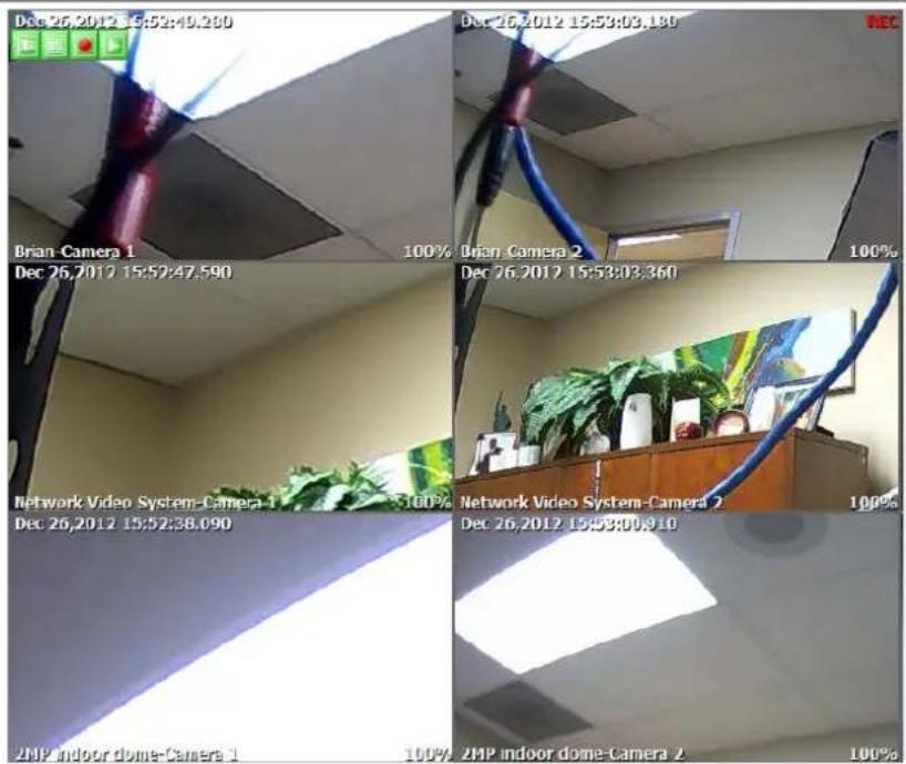
Group Circulation

Start sequencing between groups.
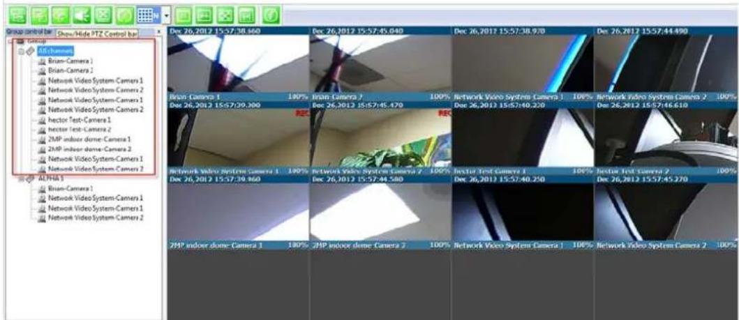

Layout settings

You can change the screen layout between 1,2,4, etc.

Image in Original Size

This allows for digital zoom.

natural_image
Interior view of a photography studio with ceiling, desk, and screen (no visible text or symbols)Draw Image by Maintaining Aspect Ratio

Maintains the aspect ratio of the camera

Draw Image by Filling the Screen

Home | Live View | Player

Enhanced Draw Mode On/Off.
Enhance image for a better reproduction.


natural_image
Exterior view of a beige door with a red rectangular highlight on the right side (no text or symbols visible)
natural_image
Exterior view of a beige door with a metal handle, partially obscured by a red rectangular overlay (no text or symbols visible)About Smart Viewer

You can see the status of the Smart Viewer

28. Configuring & Viewing Player
From the Home Screen click on Player
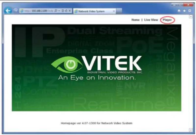
28.1. Main Window View
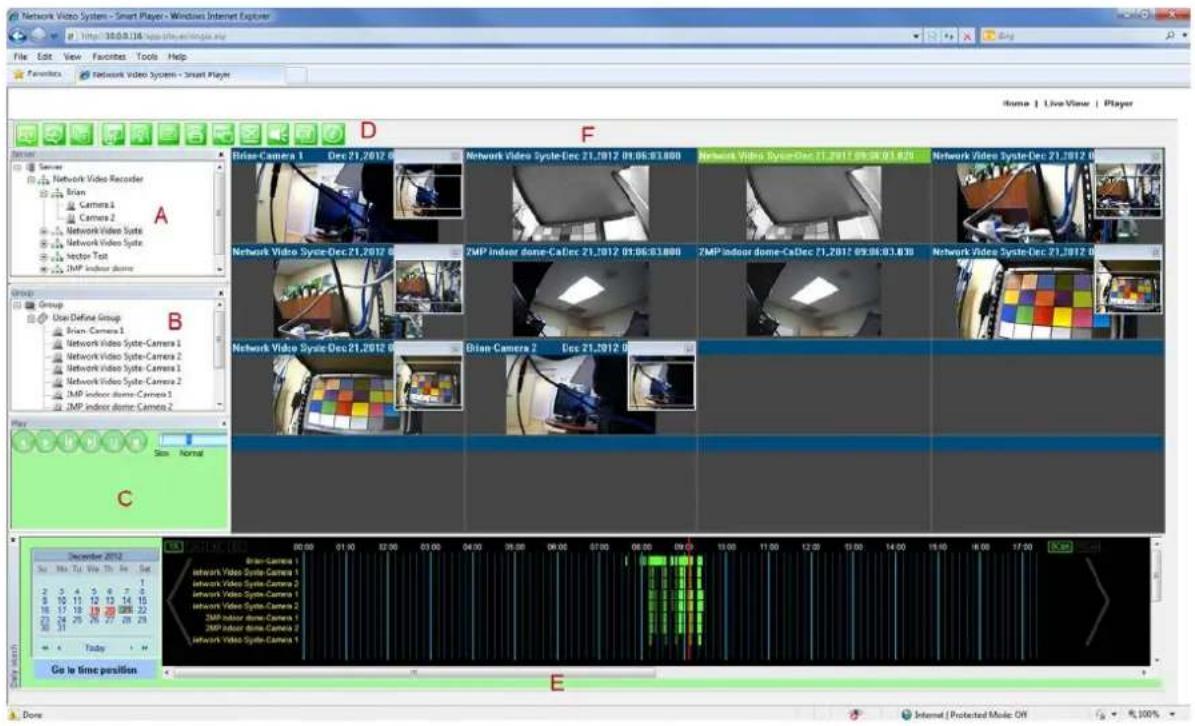
Note: The appearance of Smart Player window may vary depending on version and type of Vitek device you're using. This user's manual is based on general display screen.
Server Control Bar A
Allows you to view cameras / servers that are registered in the system.
| Group Control Bar B | You can compose a new group by dragging & dropping servers, modules, and cameras into a group. Grouping provides search function of recorded video from cameras. |
| Playback Control Bar C | Users can use this bar for functions such as forward/reverse play, previous frame, next frame, pause, stop, playback speed. |
| Control Tool Bar D | Users can change search mode between calendar, condition, and data. It also provides additional features such as backup and snapshot. |
| Time Line Control Bar E | Search condition (calendar, condition, and data) can be refined in this bar. |
| Display screen F | This screen shows multiple numbers of recorded videos. |
28.2. Connecting to NVR Player
In order to playback video, cameras must be assigned to a Group, in this section you create groups with cameras you want to playback. Playback directly from cameras with SD card installed will have "Group" automatically created and the camera assigned to that "Group"

28.3. Creating a Group
In order to generate a group in Group Control Bar, right click on Group, another window will appear then select New.
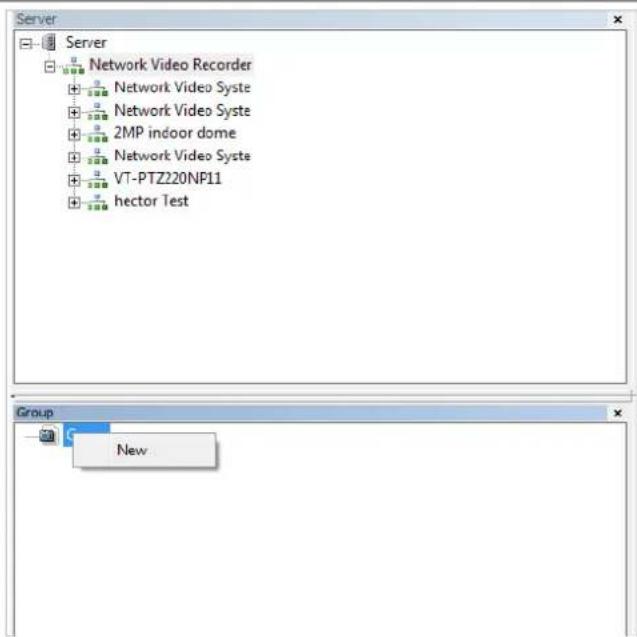
The following window will be displayed. Type in the group name and click OK.
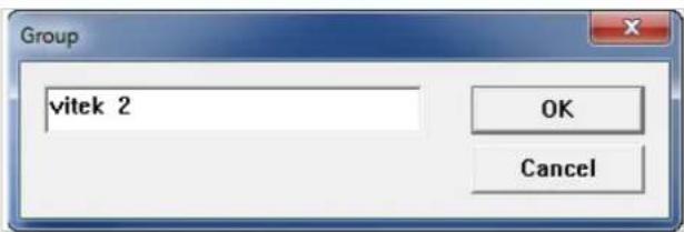
A new group with the assigned name will be created as shown below.
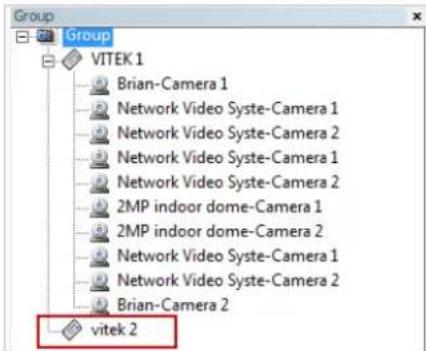
To add a camera to the new group, drag and drop from the server tree to the newly created group.
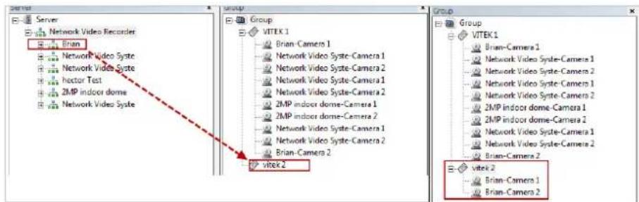
29. Searching Video
Make sure you have recorded video on the calendar (recorded video shows in red).

There are three choices in searching recorded video - Day Search, Condition Search, and Data Search.
Make sure that Camera / Server Connection and Creating Group have been performed before you search recorded video.
29.1. Searching Video
To search and playback video, Smart Player requires one or more groups to exist. If a search is executed on the basis of a selected group, a search will be performed on all the cameras in that group. If a search is executed on the basis of a single camera, the search will be performed only from that camera.
For example, if you select a group and start searching; the search from that group will be displayed
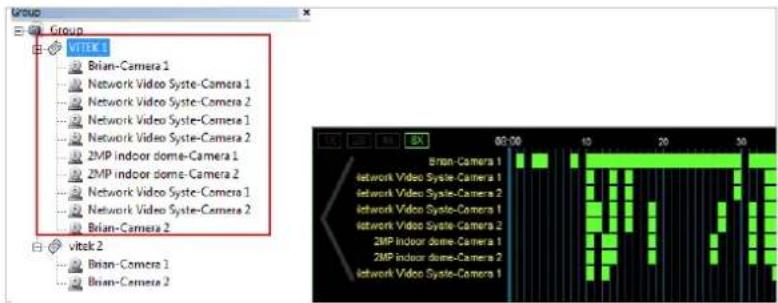
If you only select "Brian-Camera 1", the searching will be performed only on the video from that.
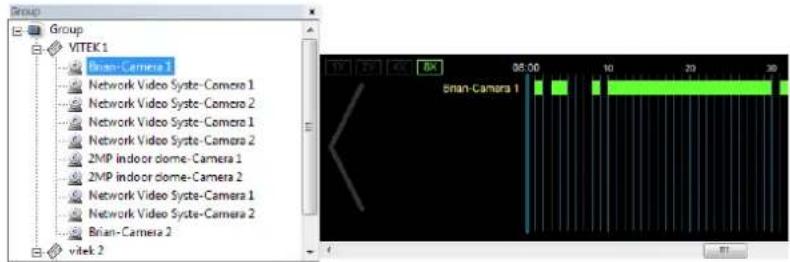
29.2. Daily Search

natural_image
Row of green square icons representing media and information categories (no text or symbols)Select date from calendar than select time from the time bar.

29.2.1. Search Mode
By clicking a date in red on the calendar, the time frame recorded is shown.
29.2.2.GO to Time Position
To go to specific time click on "Go to time position" than input time and click search.
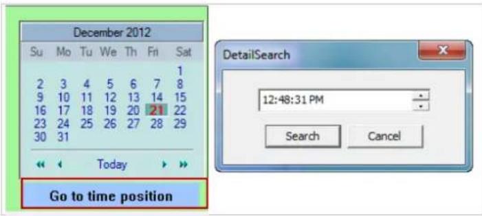
29.3. Condition Search Mode

natural_image
Green square icon grid with icons for news, computer, photo, email, and information (no text or symbols)In this mode, you can search for video on the basis of combination of 3 different conditions, which are Time, Motion, and Sensor. Initially only Time condition is available for searching, and you need to enter Advance Search mode to utilize Motion and Sensor state if necessary.
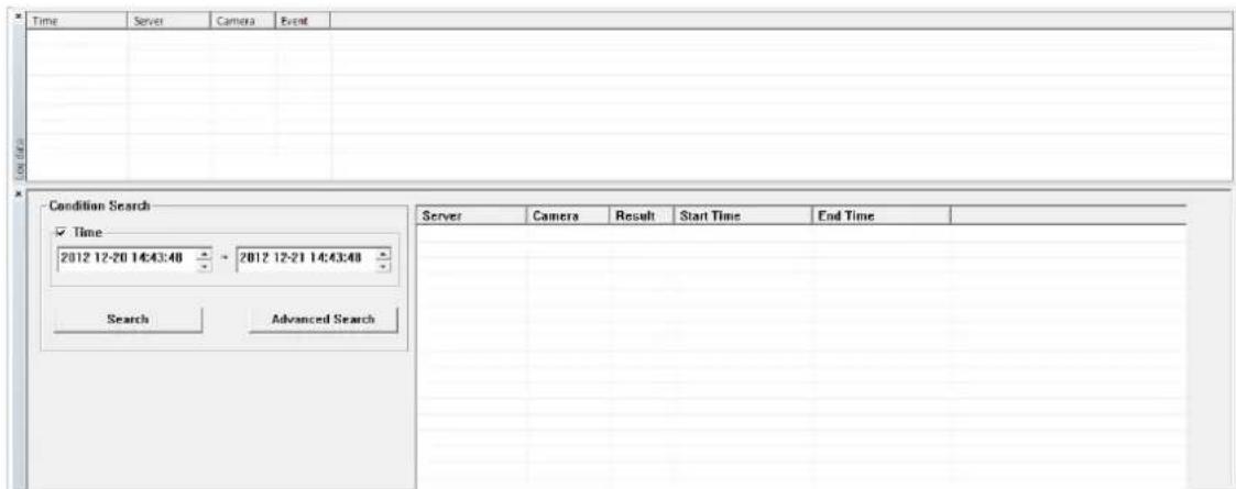
Search
Select time and date from beginning to end of search criteria. Then click Search.
The following window will be displayed to inform you of the search progress. If any results are found, the
video will start playing back right after searching is completed.
![[106500] frame searched Cancel](/content/2026/06/1213747/images/da92726891d8ae39b38344deaae5012c97485a7a2739a65a8e172401895a7b4c.jpg)
29.3.1. Advanced Search Mode
In Advance Search Mode you can select which conditions to search from (Time, Event, etc)
First, select Time checkbox, and choose the desired time frame (Start date and time \~ End date and time), and then click Add Condition button to add to Search Condition.
![Advanced search ✓ Time 2011 01-26 30:41:47 2011 01-27 30:41:47 ✓ Group, Camera Group: User Define C Camera ID: All ✓ Event Motion Sensor Motion 1 2 3 4 5 6 Alarm 1 2 3 4 5 6 Add Condition Del Condition Reset Search Condition [-1:-1][2011/01/26~2011/01/27][10:41~10:41]] Search Cancel](/content/2026/06/1213747/images/3c0be40b44475fb60dcb82ec75fea3505c5ab3bc5e2aaedda52bbefb3f2fcddf.jpg)
Now select Event checkbox, and choose Camera 1 from Motion, and then click Add Condition button to add to Search Condition.
![Advanced search Time 2011 01-26 10:41:47 2011 01-27 10:41:47 Group, Camera Groups User Define C Camera IDt All Event Motion Sensor Motion 1 2 3 4 5 6 Alarm Add Condition Del Condition Reset Search Condition [-1:-1][20:11/01/26~20:11/01/27][10:41~10:41]] [-1:-1][M1] Search Cancel](/content/2026/06/1213747/images/b9df31b8ee31907fbf597a895fec52e004678dc963356f3a744aebad6a81606c.jpg)
Next, select Event checkbox, choose Sensor 1, and then click Add Condition button to add the Sensor condition to Search Condition.
![Advanced search Time 2011 01-26 10:41:47 ~ 2011 01-27 10:41:47 Group, Camera Group: User Define C Camera ID: AI Event Motion Sensor Motion 1 2 3 4 5 6 Alarm 1 2 3 4 5 6 ✓ Add Condition Del Condition Reset Search Condition [-1:-1][2011/01/26~2011/01/27][10:41~10:41]] [-1:-1][M+1] [-1:-1][oD-1] Search Cancel](/content/2026/06/1213747/images/6e5929e5d82b9b0e4e13ff551f56b176107b6c1d79dcdf299a9e91aa5429ffd9.jpg)
Now that all the conditions have been configured, click Search button to start searching. Any video data which meets at least one of the conditions in Search Condition list will be shown as the results.
30. Video Playback Controls

 | Play Reverse | |
 | Play Forward | |
 | Pause | |
 | Stop | |
 | Back to Previous Frame | |
 | Go to Next Frame | |
 | Playback Speed Control | |
 | Player Path Control (only for condition search mode) |
31. Extra Features
31.1. Window Control
Users can open or close control windows.
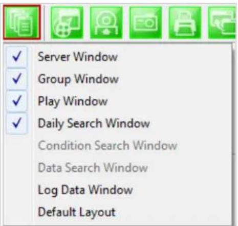
31.2. Recording Period
You can view the starting and ending date of a recorded channel.

Record time is displayed as shown below.
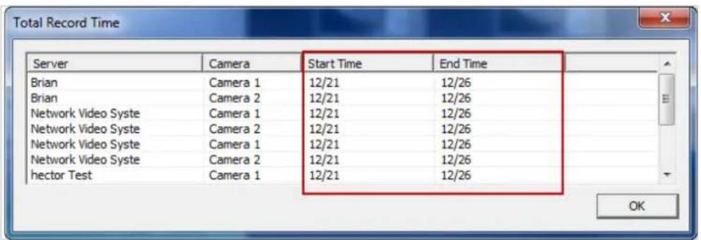
31.3. Backup
There are two backup formats IDX and AVI.
.IDX
Default video file format used by Vitek
.AVI Video file format supported by Microsoft Windows

natural_image
Row of green square icons representing media and information symbols (no text or labels)When the Backup button is clicked, the following window is displayed as below.

| Select Camera | Check the camera to backup. For AVI backup, only one camera is permitted. For FJP, IDX, multiple backup is allowed. |
| Backup Period | Select the time frame (Start date and time ~ End date and time) to backup. |
| Backup Type | Select either AVI or FJP, IDX format. |
| Backup Path | Select the HDD path where the backup file will be saved. |
After selecting the parameters, click OK then the following window will display.
![[16833] frame searched Cancel](/content/2026/06/1213747/images/400c02fe6f5cdc47aef0c4eb9906fde27a565064b45eef4f410bc8b911de508b.jpg)
After searching is finished, backup operation will start.
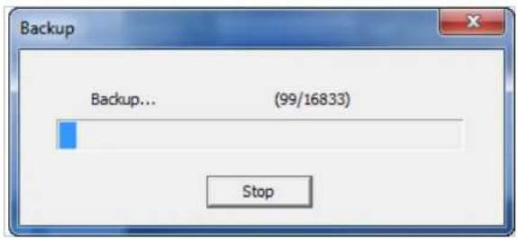
When backup is completed, the following window will appear. Click OK button.

Note: For AVI file backup, only one camera is allowed. For IDX backup, multiple cameras are allowed.
31.4. Snapshot
Choose the camera currently being played or paused, click Snapshot button. Then a snapshot file will be saved in a designated path.

The below picture is a result of snapshot from the above window.

31.5. Print
Choose the camera currently being played or paused, then click Print button. Then the image of the selected camera will be sent to your default printer.

natural_image
Row of green square icons representing media and information symbols (no text or labels)31.6. Ratio Display
You have three options to view videos, which are Original, Ratio, and Stretch.

natural_image
Green square icon set with various application icons (no text or symbols)
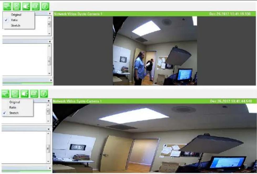
32. EN-V-R Configuration
32.1. System, Network Configuration
General system and network properties of EN-V-R program can be set up in this section. To start, select System, Network Configuration from the menu list.
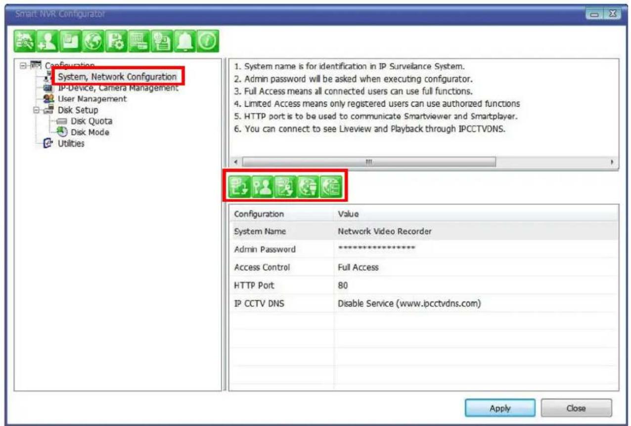
Items Descriptions

System Name Setting Enter the system's name.

Set up Admin password Modify the password for Admin.

Access Control Configure the access privileges of users.

HTTP Port Assign Assign an HTTP Port for EN-V-R Service.

Configure IP-CCTV DNS Configure IP-CCTV DNS for EN-V-R Service
32.1.1.Configuring System name


To name the system, click configuring system name, the following window will be displayed. Change the name as desired.
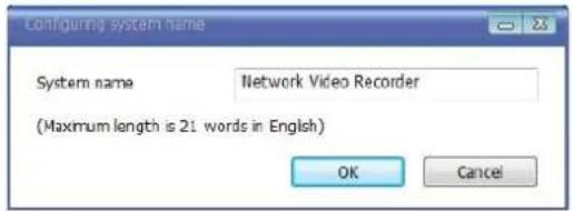
Items Descriptions
| System name Type in a System name. | |
| OK | Click this button to apply the entered System Name. |
| Cancel | Click this button to discard the configured System name. |
32.1.2. System, Network Configuration - Admin password

To assign Password for the admin, click System, Network Configuration on the menu tree. Click configure admin password
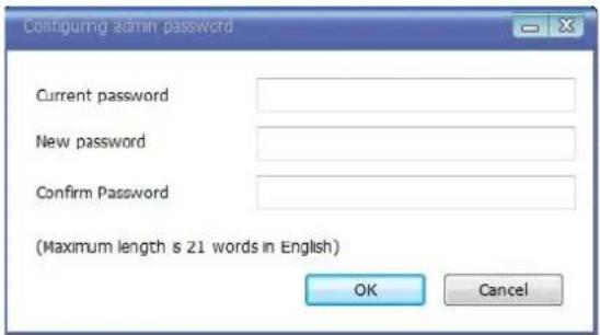
Items Descriptions
| Current password | Enter the Current password. |
| New password | Enter a new password to use. |
| Confirm Password | Enter the new password again to confirm. |
| OK | Click this button to apply the changed password. |
| Cancel | Click this button to discard the change. |
32.1.3. System, Network Configuration - Access Control

To configure User Access Control, click System, Network Configuration on the menu tree. Click configure access control

Items Descriptions
| Full Access | Set Full Access for the user. Anyone can connect to the EN-V-R without authentication, and be allowed live view, audio, PTZ, playback. |
| Limited Access | Set Limited Access for the user. Only the users with proper permission to the camera can access it. |
| OK Click this button to apply the change. | |
| Cancel | Click this button to discard the change. |
32.1.4. System, Network Configuration - HTTP Port

To configure HTTP port to use, click System, Network Configuration on the menu tree. Then click Change HTTP Port
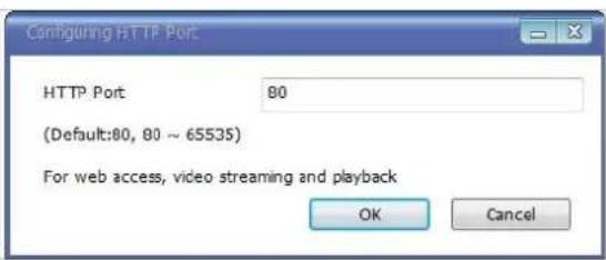
Items Descriptions
| HTTP Port | Enter a HTTP Port to use in the EN-V-R Service. (Default is 80) |
| OK Click this button to apply the changed HTTP port number. | |
| Cancel | Click this button to apply discard the changed port number. |
Note: If a firewall is enabled in your Windows, you should set the above HTTP port number to be allowed in your computer.
32.1.5. System, Network Configuration-IP CCTV-DNS

To configure IP CCTV-DNS, click System, Network Configuration on the menu tree. Click
Configure IP-CCTV-DNS

Items Descriptions
| Service | Set to use IP CCT DNS or not. |
| DNS Server IP Vitek IP CCTV DNS address already entered. | |
| Go Server Directs to Vitek IP CCTV DNS server | |
| MAC | MAC address of EN-V-R already entered |
| Product Key | Product Key of EN-V-R already entered |
| External Port | Enter an external HTTP Port to use for IP CCTV DNS service. (Default is 80) |
| Register verify | Click to test the connection with IP CCTV DNS server after setting is done in IP CCTV DNS server. |
| OK | Click this button to apply the changed IP CCTV DNS settings. |
| Cancel | Click this button to discard the changed IP CCTV DNS settings |
33. IP-CCTV DNS Registration
To register your camera / server please visit http://www.ipcctvdns.com
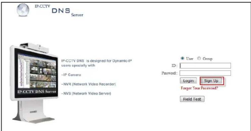
If this is your first visit your need to Sign Up if you abide by the Agreement, click on "I Agree"
than on the NEXT button as shown below.
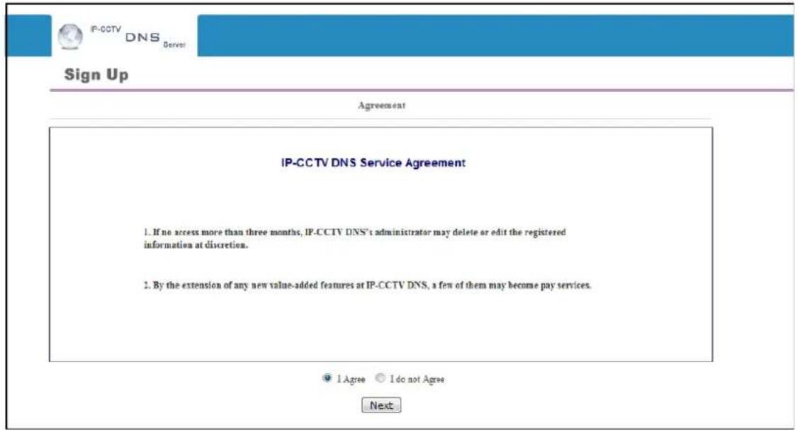
Fill out the requested information as shown below and click on Apply.
![IP-CCTV DNS Server Sign Up Membership ID [E-Mail] * vitek@vitekcctv.com check Password * ************ Confirm Password * ************ Name * VITEK Company VITEK Telephone * 6612948043 Mobile Phone 6612948043 Address 28492 Coentellation Rd Valancia CA 91355 Country * Los Angeles (USA) Description Apply Reset](/content/2026/06/1213747/images/d92e3b0d504e94b83c6083161559899b44ff3a4601d9985b0183eb2168a3754c.jpg)
The following screen will confirm that your Membership has been completed successfully, that click OK.
You will be brought back to the main page of the IPCCTVDNS website; in this case you need to Login with the information previously created.

To register your first product, click on Product Registration as shown below.

Enter the requested information (The name of your camera, the Mac Address and product Key) as shown below.
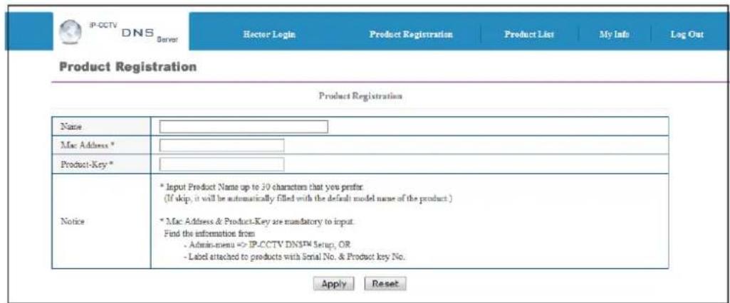
Note that the Mac Address and the product Key will be available under the Network Configuration>> IP-CCTV DNS setup in the camera menu. Please see image below.
IP-CCTV DNS™ Setup
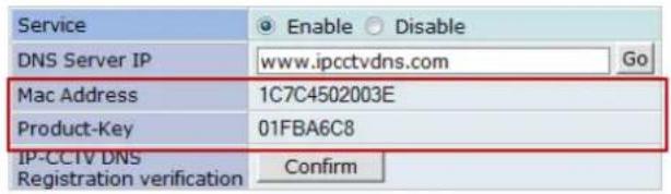
A window will pop up confirming that your product has been registered successfully, click on OK.
You will be directed to the Product List page where you will be able to see your recent camera registration.
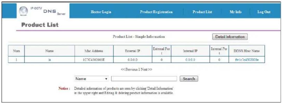
By clicking the Detail Information tab you will be allow edit DDNS Host Name

Click Edit to change the DDNS Host Name.

Type in desired host name than click Apply.
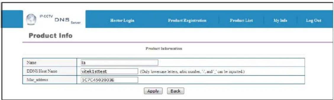
A window will pop up asking if you really want to apply the new configurations, to continue click OK.
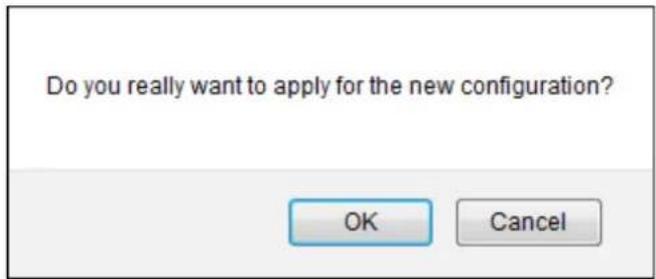
A window will pop up confirming that the product information has been modified successfully, click OK.
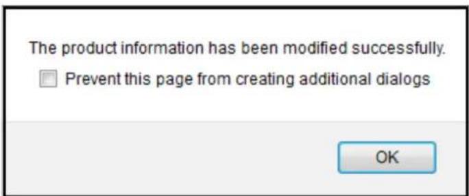
Click under Product List to view your changes
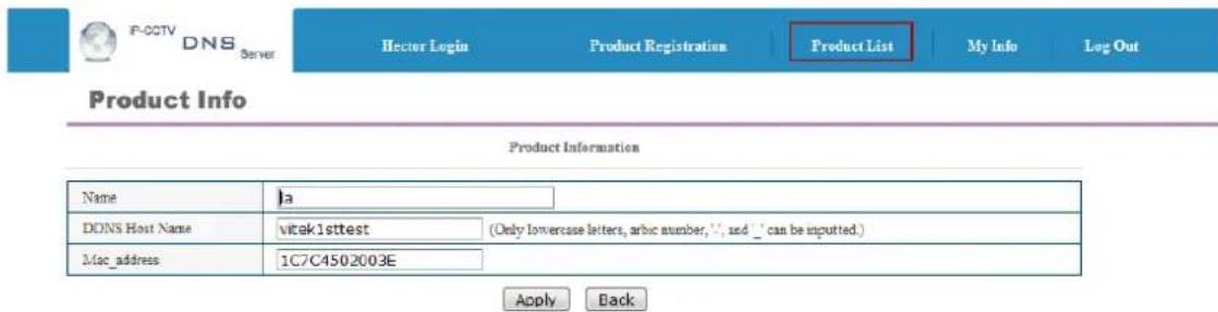
Your camera with the new DDNS Host name will be displayed.

Your camera is now registered and ready for use.

34. IP-Device Registration
You will see how to manage IP devices in this section, which includes registering, modifying, and deleting IP devices. To start managing IP devices, select IP-Device, Camera Management from the menu list.
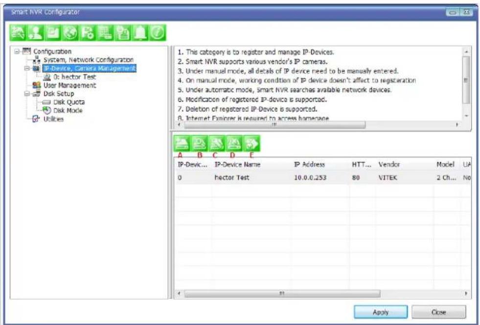
| Items Descriptions | |||
 | A | IP-Device Manual Registration | Register IP-Devices manually by users. |
 | B | IP-Device Automatic Registration | Scan and register IP-Devices automatically by the program. |
 | C | IP-Device Modification | Modify the information of registered IP-Devices. |
 | D | IP-Device Deletion | Delete IP-Devices previously registered. |
 | E | IP-Device Homepage | Go to the homepage of the IP-Device. |
34.1. IP-Device Registration (Manual)


To manually register an IP-Device, click IP-Device, Camera Management on the menu tree. Click Register IP device manually.
![Registering New IP-Device Inputting IP-Device information IP-Device ID A 0 Vendor B VITEK Model C 4 Channel Model Name D SmartNVR 1 IP Address E 10.10.237.120 Input IP Address Range F - Getting Information from IP-Device G (May take several minutes) VS Module ID H 0 HTTP Port I 80 RTSP Port J 554 Login ID K root Login Password L ••••• Confirm Password M •••••• Checking available resolution QCIF [QQVGA] 176 X 144 ~ 160 X CIF [QVGA] 352 X 288 ~ 320 X Half D1 (Half VGA) 704 X 288 ~ 640 X D1 (VGA) 704 X 576 ~ 640 X SVGA 800 X 600 ~ 720 X O XGA 1024 X 768 HD720 (720P) 1280 X 720 SXGA 1280 X 1024 UXGA 1600 X 1200 QXGA 2048 X 1536 Checking available PTZ cameras Camera1 Camera2 P Camera3 Camera4 Save Cancel](/content/2026/06/1213747/images/60bf7ca5088295242f90a6947283e746e4d603854590eb05a071a05c1f0add40.jpg)
Item Description
A IP-Device ID
Select the IP-Device ID to register.
Select the Vendor name of the IP-Device to register. Click the pull-down list, and choose a proper vendor name from the list.
B Vendor
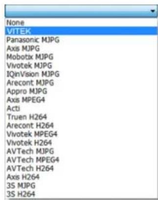
C Model
Select the total number of channels (streams) the IP device has. Click the pull-down list, and choose proper one from the list.
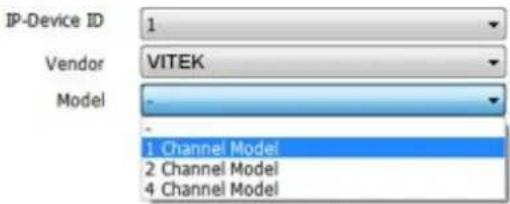
| D | Name | Type in the name of the IP-Device. |
| E | IP Address | Type in the IP Address to use with the IP-Device. IPCCTVDNS or URL addresses are also supported. (If Input IP Address Range box is checked, then the starting address of the range will be selected.) |
| F | Input IP Address Range | Enter the last IP address of the range. |
| G | Getting Information from IP-Device | Check this box if the information from IP-Device needs to be acquired. |
| H | VS Module ID | Select the VS Module ID. Enter 0 for non-Vitek IP devices. Vitek products can be set to 0 to 15, and default is 0. |
| I | HTTP Port | Enter the HTTP Port to use with the IP-Device. (Default is 80) |
| J | RTSP Port | Enter the RTSP Port (Default is 554) |
| K | Login ID | Type in the Login ID to use. (Default is root) |
| L | Login Password | Type in the Login Password to use for the Login ID. (Default is root) |
| M | Confirm Password | Type in the same password to confirm. (Default is root) |
| O | Checking available resolution | Select the Video Resolution for the device. Not used, all resolution is done at camera level |
| P | Checking available PTZ camera | Checkboxes to choose if PTZ is supported on the IP device. |
| Q | OK | Click this button to apply the configured values. |
| R | Cancel | Click this button to discard the configured values. |
34.2. IP-Device Registration (Automatic)
To register an IP-Device by automatic scanning, click IP-Device, Camera Management on the menu tree. Then Click Scan available IP devices and register
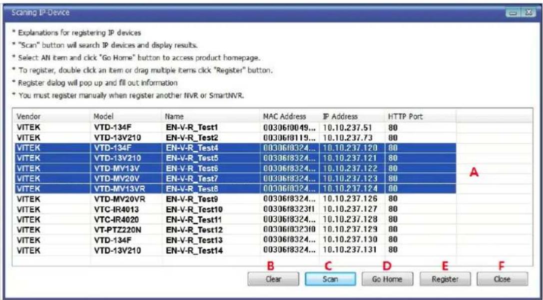
Items Descriptions
| A | IP-Device list | This list shows the IP devices found during the scan process. If you need to select multiple IP devices at the same time, drag your mouse over the devices or keep pressing CTRL or SHIFT key while clicking the IP devices. |
| B | Clear | Clear the scanned IP Devices from the list. |
| C | Scan | Start scanning for IP Devices on the network. |
| D | Go Home | Go to the home page of the IP device selected from the list. |
| E | Register | Go to the registration window for the IP Device selected. |
| F | Close | Cancel the registration of the IP device and exit the window. |
When you click the Register button after selecting more than one IP devices on the scanned device list, the following window will be displayed. You can register those IP devices to your EN-V-R in this window.

| Items Descriptions | |
| A Resolution Description | Descriptions of the image resolution modes in the IP-Device list.(R1, R2, R3, R4, R5, R6, R7, R8, R9, R10) |
| B PTZ Install Description | Descriptions of the PTZ numbers in the IP-Device list.(P1, P2, P3, P4) |
| C IP-Device list | IP-Device list to select from. |
| D Apply to All | Click this button to copy the information of a selected IP-Device to all other devices.(Only Model, Login ID, and Login Password will be copied.) |
| E Register | Click this button to confirm and save the registered IP-Device added. |
| F Cancel | Click this button to cancel IP-Device registration. |
IP-
Device Modification

To modify an IP-Device registration, Click Modify registered IP-Device

| Items | Descriptions | |
| A | IP-Device ID | IP-Device ID is displayed. (not allowed to modify) |
| B | Vendor | Select the Vendor of the device. |
| C | Model | Select how many channels the device support. |
| D | Name | Change the Name as required. |
| E | IP Address | Enter the IP Address to use with the selected device. |
| F | Input IP Address Range | (not allowed to modify) |
| G | Getting Information from IP-Device | (not allowed to modify) |
| H VS Module ID | Select the VS Module ID. Enter 0 for non-Vitek IP devices. Vitek products can be set to 0 to 15, and default is 0. | |
| I | HTTP Port | Enter the HTTP Port to use with the IP-Device. (Default is 80) |
| J | RTSP Port | Enter the RTSP Port (Default is 554) |
| K | Login ID | Type in the Login ID to use. (Default is root) |
| L Login Password | Type in the Login Password to use for the Login ID. (Default is root) | |
| M | Confirm Password | Type in the same password to confirm. (Default is root) |
| N | Checking available resolution | Select the Video Resolution for the device. Not used, all resolution is done at camera level |
| O | Checking available PTZ camera | Checkboxes to choose if PTZ is supported. |
| P | OK | Click this button to apply the changed values. |

Cancel
Click this button to discard the changed values.
34.3. IP-DeviceDeletion
To delete a registered IP-Device, click IP-Device, Camera Management on the menu tree in the left pane. Then select an IP device to be deleted from the list. Click Remove IP-Device registration
To go to the home page of an IP-Device, click the IP-Device, Camera Management on the menu tree. Then select the IP device. Click Go to IP-Device homepage
34.5. Camera Management
In this section, you will see how to manage the device information, video resolutions, recording configuration, and alarm event configuration. Firstly, select a camera name under IP-Device, Camera Management on the menu tree.
When you select IP-Device, Camera Management on the menu tree, it will show the Camera Management sub-menu. You can configure cameras here. The following picture shows when you selected an IP-device in the menu tree. The sub-menu toolbar changes accordingly to your selection.

Items Descriptions
 | A | Camera Information | Configure Information of the selected camera. |
 | B | Resolution and Quality | Choose the resolution and quality of cameras. |
 | C | Recording Conditions | Set up recording conditions. |
 | D | Alarm and Map service settings | Configure Alarm and Map service functions. |
34.5.1. Configure Camera Name and Information

From the configuration list, select a camera to be assigned with a name.
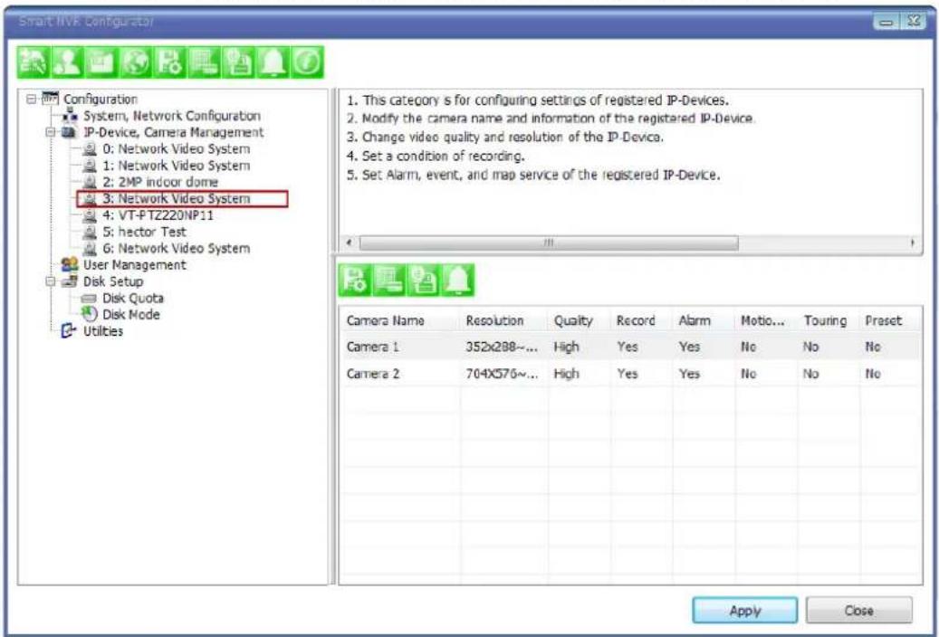
Then click on camera1 or camera 2, and then click Configure Camera Name and Information
| Camera Name | Resolution | Quality | Record | Alarm | Motio... | Touring | Preset |
| Camera 2 | 704X576~... | High | Yes | Yes | No | No | No |
| Camera 1 | 352x288~... | High | Yes | Yes | No | No | No |
The below image will be display, enter name (F), then click Apply to camera (H), then OK.
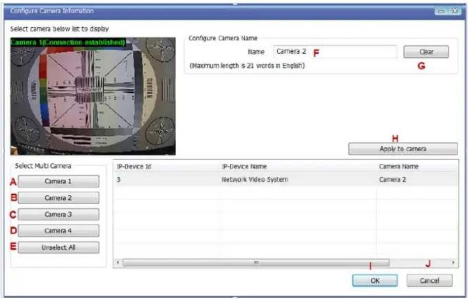
| Items Descriptions | ||
| A,B,C,D | Camera Selection | Select one or more cameras for name assignment by clicking buttons. |
| E | Unselect All | Clear the device list which shows the selected cameras. |
| F Name | Type in a camera name. | |
| G | Clear | Clear the camera name field. |
| H | Apply to Camera | Apply the changed camera name to the system. |
| I | OK | Click this button to confirm the change and close the window. |
| J | Cancel | Click this button to cancel the change and close the window. |
34.5.2. Camera Resolution, Quality

To configure a camera's resolution and video quality, select a camera to configure and click Configure camera resolution and quality
| Camera Name | Configure camera resolution and quality | Alarm | Motio... | Touring | Preset | ||
| Camera 1 | 352x288~... | High | Yes | Yes | No | No | No |
| Camera 2 | 704X576~... | High | Yes | Yes | No | No | No |
The below image will be display, adjust resolution (F), then click Apply to camera (H), then OK

| Items Descriptions | ||
| A,B,C,D | Camera Selection | Select one or more cameras by clicking buttons. |
| E | Unselect All | Clear the device list which shows the selected cameras. |
| F Resolution Select the video resolution. | ||
| G Quality Select the video quality. | ||
| H | Apply to Camera | Apply the selected video resolution and quality to the system. |
| I | Go Home | Go to the homepage of the product. |
| J | Close | Close and exit the window. |
34.5.3. Configure Camera Recording Condition

To configure recording conditions, select a camera to configure, then click Configure camera recording condition
| Camera Name | Configure camera recording condition | Alarm | Motio... | Touring | Preset | ||
| Resolution | Quick | Record | |||||
| Camera 1 | 352x288~... | High | Yes | Yes | No | No | No |
| Camera 2 | 704X576~... | High | Yes | Yes | No | No | No |
The below image is where you adjust the recording parameters.
![Configure Recording Condition 1. Select camera to configure condition 2. You can select to multi camera 3. Select condition to configure record condition 4. Configure detail schedule and event 5. Click Apply to camera button to apply condition 6. Change record service Pre, Post images 7. Click Apply to camera button to save changed condition Camera 1(Connection established) Recording Service Enable Recording Service Disable Recording Service Pre Alarm Images 0 Pre Alarm Speed fastest POST Alarm Images 0 POST Alarm Speed fastest Camera list Select Multi Camera A B C D E Configure Recording Condition Input Condition Use the condition G Do not use this condition Condition Mode Always Recording H Recording by schedule only Recording by event only Recording by schedule and event Schedule Day of week Sun Mon Tue Wed Thu Fri Sat. Time 1 12/31/1969 ~ 12/31/1969 Date 12/31/1969 ~ 12/31/1969 Event: Alarm Sensor 1 2 3 4 Motion Detection J External Input Data K Condition list F Apply to condition Camera Name Con... Condition Name Camera 1 1 [N1] Camera 1 2 - Apply to camera L IP-Device Id IP-Device Name Camera Name Recording Condition 1 Condition 2 Condition 3 Conditc 3 Network Video System Camera 1 Enable [N1] - - - OK Cancel](/content/2026/06/1213747/images/00ddeac5e083f8813e7acf6ee950b67dc502095ce1d6c83cffa39823de4e6f22.jpg)
Item Description
| A,B,C,D | Camera Selection | Select one or more cameras by clicking buttons. |
| E | Unselect All | Clear the device list which shows the selected cameras. |
| F | Condition List | Define the condition for recording to be started. |
| G | Condition to use | Decide whether to use the defined condition or not. |
| H | Condition Mode | Select the condition mode for recording. |
| I | Scheduling | Set up the schedule for recording. |
| J | Event setup | Set up the event to initiate recording. |
| K | Apply to Condition | Apply the configured schedule and event data to condition list. |
| L | Apply to Camera | Apply the condition to camera. |
| M | Enable Recording Service | Enable this to activate the recording. When this is not enabled, it won't be saved if a recording condition is set. |
| N | Pre Alarm Images | Select pre-alarm images. |
| O | Pre Alarm Speed | Select pre-alarm speed. |
| P | Post Alarm Images | Select post-alarm images. |
| Q | Post Alarm Speed | Select post-alarm speed |
| R | OK | Click this button to confirm the change and exit the window. |
| S | Cancel | Click this button to cancel the all the changed made in this session. |
To setup recording, first click camera under Condition list (F). This enables the Configure Recording Condition (G, H, I and J)
| Camera Name | Con... | Condition Name | |
| Camera 1 | 1 | [M1] | |
| Camera 1 | 2 | - |
Now you can select your condition mode (H). Under condition mode you have four choices always, schedule, event and schedule and event. (In this example we will record by event only)
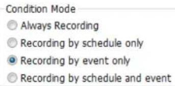
Schedule: To schedule time and date of recording (I). (When schedule is activated in condition mode)
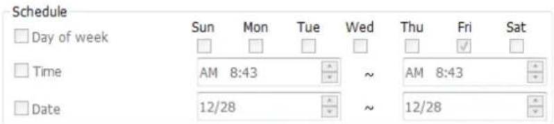
Event: Here you can select Alarm or Motion (J)

After completing your conditions selection click Apply to condition (K) After apply to condition click Apply to camera (L), and then click OK(R) When that screen closes click Apply

34.5.4. Alarm, Event Configuration

To configure the Alarm and Event features, select a camera to configure, and then click Configure alarm, map service
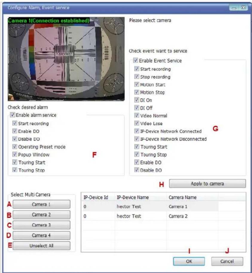
Item Description
| A,B,C,D | Camera Selection | Select one or more cameras by clicking buttons. |
| E | Unselect All | Clear the device list which shows the selected cameras. |
| F | Alarm Service Setup | Put check marks on alarm types to use. |
| G | Event Service Setup | Put check marks on event types to use. |
| H | Apply to Camera | Click this button to apply the changes to the camera. |
| I | OK | Click this button to confirm the change and exit the window. |
| J | Cancel | Click this button to cancel the Alarm, Event configuration. |
34.6. User Management
In this section, you will see how to manage user information. To start managing users, select User Management from the menu tree.

| Items | Descriptions | ||
 | A | User Registration | Register new users to the system. |
 | B | User Modification | Change the information of existing users. |
 | C | User Deletion | Remove the account of existing users. |
34.6.1.User Registration

To register a new user, click the 1'st button on the tool bar in the sub-menu toolbar.
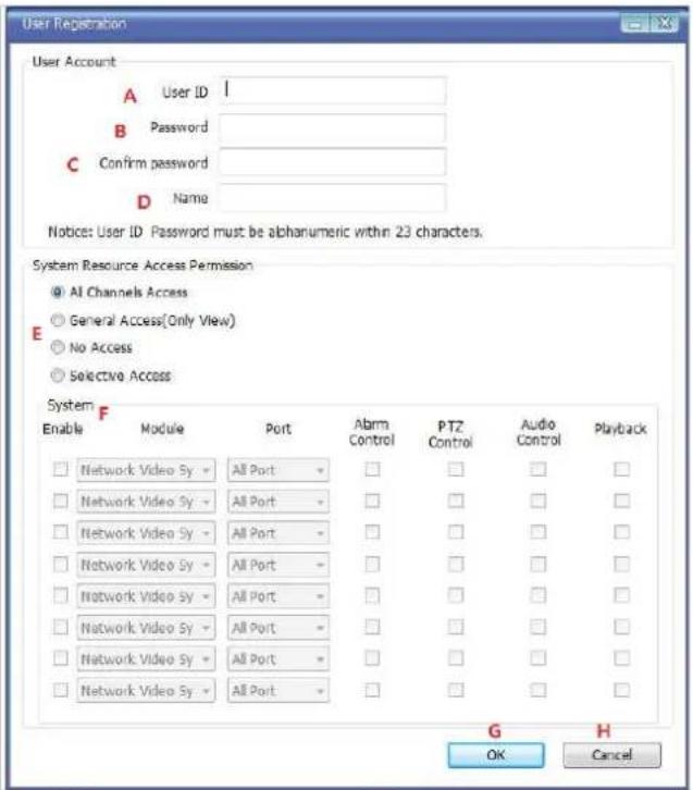
| Items Descriptions | ||
| A | User ID | Enter a new User ID to register. |
| B | Password Enter the Password for the new user. | |
| C | Confirm password | Enter the same Password for confirmation. |
| D | Name | Enter the name of the new user to be registered. |
| E | System resource access permission | Choose the level of permission for System resource access.All channels access: Viewing all cameras, Alarm, PTZ, Audio, SearchingGeneral access: Viewing all cameras onlyNo access: An user account without any access to camerasSelective access: Access to only selected cameras and privileges. |
| F | System Permission | Eight different modules can be set. The setup can be made on Module, camera, alarm, PTZ, Audio, and Search respectively. Enabling each module gives access permission to it. |
| G | OK | Click this button to apply the registration of the new user. |
| H | Cancel | Click this button to cancel the registration process. |
34.6.2.User Modification
To modify a user's information, select the users name than click the second button on the submenu toolbar. The User Registration window will come up on the screen, make the necessary changes and click OK.
34.6.3.User Deletion

To delete an existing user, select the user name than click Remove Registered user account, another screen will pop up confirming to proceed with deletion, click OK to proceed.
34.7. Disk Setup
34.7.1. Disk Setup
When you click Disk Setup on the menu tree, it will show two sub-menu items. One is Disk Quota, and the other is Disk Mode. The following window shows the Disk Quota mode.
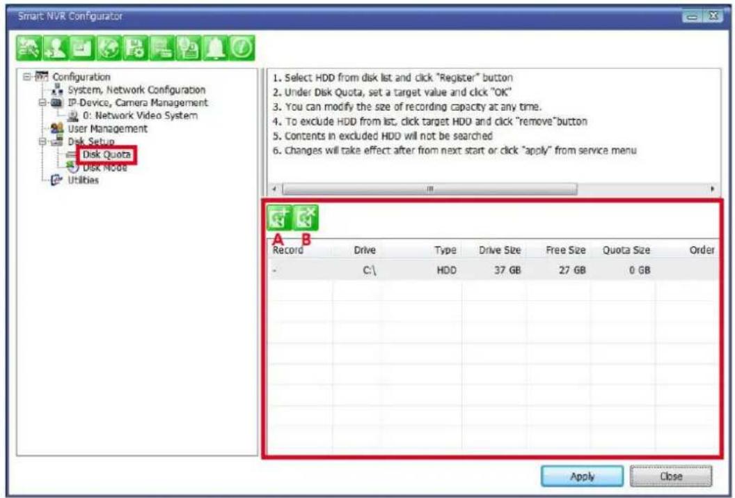
Items Descriptions

A Disk Quota Setup
Define the HDD for recording and configure the size of quota.

B Disk Quota Deletion
Delete previously assigned disk quota.
34.7.2. Disk Quota Modification and Deletion

When EN-V-R program is installed, all local drives are assigned as recording devices. To modify the disk quota for recording, click Disk Quota on the menu list, and select the drive to be modified.
To change the disk quota size, click the 1'st button on the sub tool bar, or double click the drive on the device list. The following window will be displayed.

| Item Description | ||
| A | Use HDD | Decide whether this HDD is to be used. |
| B | Possible Maximum Quota | Display Possible maximum quota on this HDD. |
| C | Possible Minimum Quota | Display Possible minimum quota on this HDD. |
| D | Set Quota | Enter the desired size of disk quota for recording. |
| E | OK | Click to apply the configured disk quota. |
| F | Cancel | Click to cancel the disk quota configuration. |
To delete the existing disk quota, click Disk Quota on the menu list. Then choose the drive quota to be deleted. Click the 2'nd button on the sub tool bar.
34.7.3. Disk Mode Change
To modify the disk circulation style, click Disk Setup, and then Disk Mode on the menu tree.
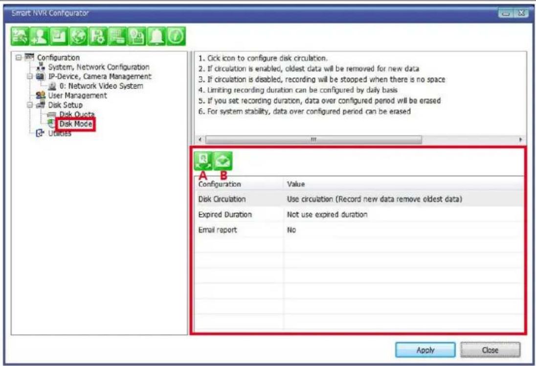
| Items Descriptions | ||
| A | Disk Circulation Setup | Configure disk circulation type. |
| B | Disk Usage Report Setup | Configure email address for reporting. |

Click the Disk Circulation in the list. The following window will be displayed.
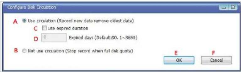
| Item | Description | |
| A | Use circulation | Select this if disk circulation will be used. |
| B | Not use circulation | Select this if disk circulation will not be used. |
| C Use expired duration | Decide whether the expiration will be used for recording. (This can be seen when “Use circulation” is selected.) | |
| D | Expired days | Enter the date when the recorded content will expire. |
| E | OK | Click this to apply the Disk circulation settings. |
| F | Cancel | Click this to Cancel Disk circulation settings. |
Configure email reporting for disk usage

To modify the email notification behavior for hard disk recording.
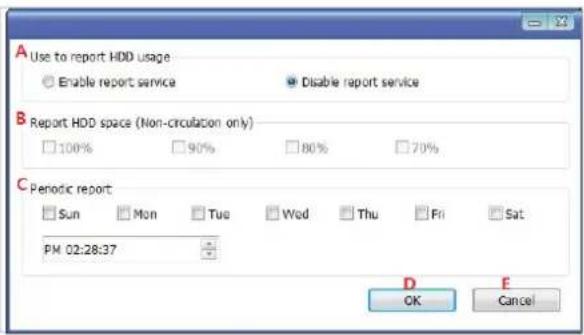
Item Description
| A | Use to report HDD usage | Choose whether to Enable or Disable the report service. |
| B | Report HDD space | When disk circulation is not used, select the HDD size when it will be reported by email. |
| C | Periodic report | Define when Periodic reports will be sent. |
| D | OK | Click to apply the Email report settings. |
| E | Cancel | Click to cancel Email report configuration. |
34.8. Utilities
Select Utilities from the menu tree. You can perform two functions in Utilities, one is Email Account Configuration and the other is About Program.
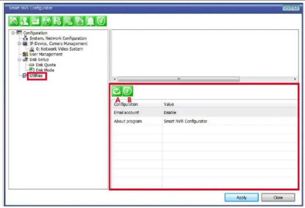
Items Descriptions

A Email Account
Configure email account.

B About Program
Display the information of EN-V-R program.
34.8.1. Email account Configuration


Once an email account is registered here, you can receive email notification from the EN-V-R program upon certain events. To configure an email accounts, click Utilities on the menu tree. Click Configure email account for mail service

Item Description
| A | Service | Decide whether to report HDD usage by email or not. |
| B | SMTP server | Enter the address of SMTP server for sending email. |
| C | Authentication | Decide whether to use Authentication. |
| D | Email user id | Enter the sender's id for email account. |
| E | Email user password | Enter the password of the sender's email account. |
| F | Sender email | Enter the Sender's email address. |
| G,H,I | Recipient email #1,2,3 | The email addresses of three Recipients to be notified. |
| J | Email subject | Enter the title of the Email when it's sent. |
| K | OK | Click to apply the Email account registration. |
| L | Cancel | Click to cancel this configuration. |
34.8.2. About Program

To displays the information of this program on the screen, Click Information of this program.
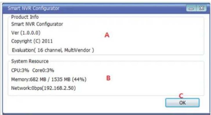
| Items | Descriptions | |
| A | About program | Show the information about the EN-V-R running. |
| B | System Resource | Displays the PC's system resource information. |
| C | OK | Click this button to close the Window. |
35. Using EN-V-R Controller
To open EN-V-R controller, click Start > All Programs> Vitek> SMART NVR Controller.
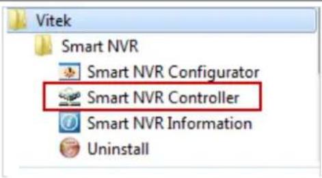
Smart NRV controller will be on the lower right part of the system tray. Then right click the icon a sub-window will display, click on Open Smart NVR Controller.

The following window will open
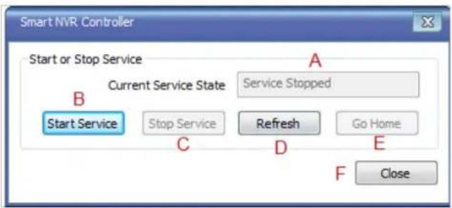
| Items Descriptions | ||
| A | Current Service State | Shows whether EN-V-R Service is running or stopped. |
| B | Start Service | Click this button to start EN-V-R Service when it's stopped. |
| C | Stop Service | Click this button to stop EN-V-R Service when it's running. |
| D | Refresh | Refresh the Screen. |
| E | Go Home | Go to the EN-V-R's built-in webpage. |
| F | Close | Close the EN-V-R Controller window. |
36. Connecting to EN-V-R
36.1. PC with EN-V-R installed
You can connect to EN-V-R in various ways as explained below.
- Click Go Home in EN-V-R Configurator

natural_image
Green square icon set with icons for data analysis, computer, globe, and communication (no text or symbols)• EN-V-R Controller window.
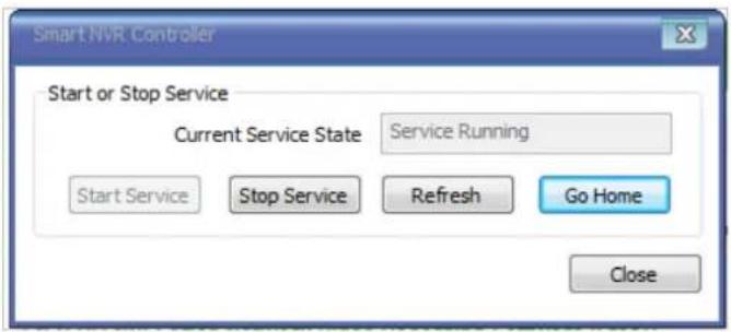
- Click Go Home from the pop-up menu on the System Tray.
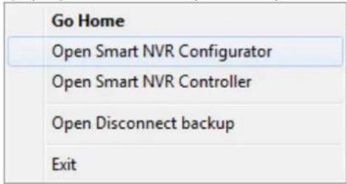
• In Internet Explorer, enter the IP address of the computer that EN-V-R is running on.

- In case that the HTTP port for EN-V-R is not 80 (default), the port number should be entered together with the IP address. (the example below assumes HTTP port of 7777)

After you successfully connecting to the EN-V-R homepage, you will see the following window.
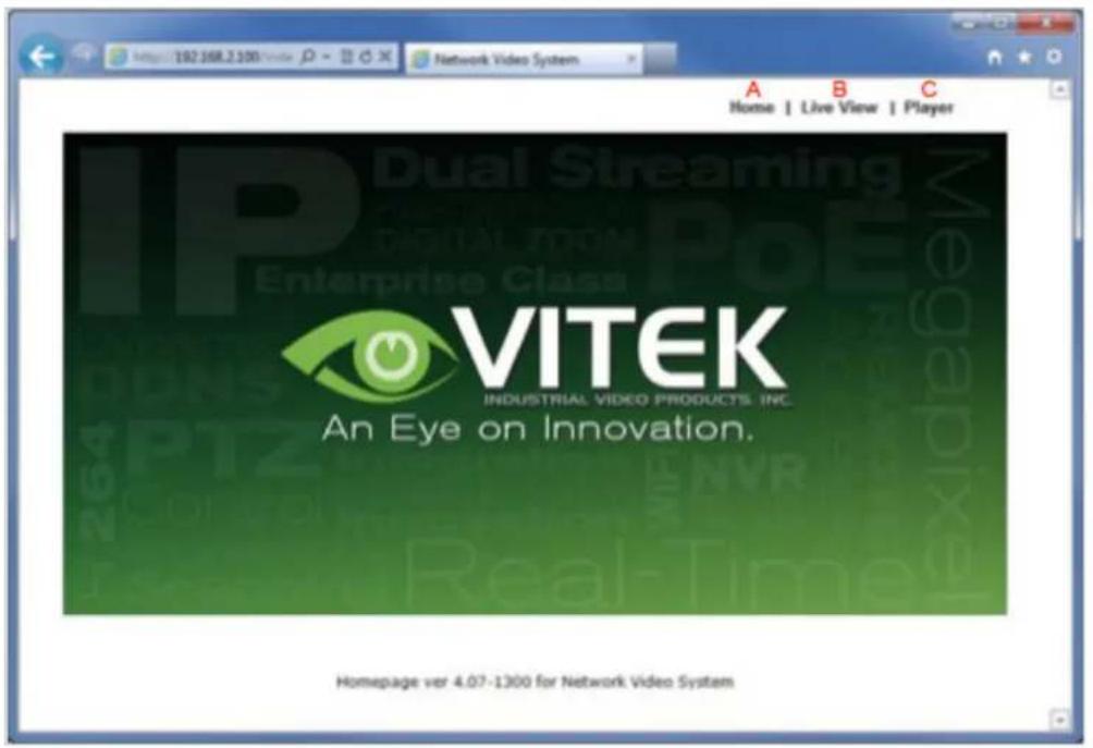
Items Descriptions
| A Home | Go to EN-V-R's homepage. |
| B Live View | Click this button to execute Live View program. You can use various features such as live view, audio transmission, PTZ control, unconditional recording, etc. |
| C Player | Click this button to search, record, and back up the video data sent from IP devices registered in EN-V-R. |
36.2. PC without EN-V-R
- If your PC doesn't have EN-V-R program installed, type in the IP address of the PC where EN-V-R is running.
Note: Refer to Section 19 ENVI Series Viewer 79 for details on how to use ENVI Viewer program. Refer to Section 29 ENVI Smart Player on page 112 for details on how to use ENVI Smart Player program.

- In case that the HTTP port for EN-V-R is not 80 (default), the port number should be entered together with the IP address. (the example below assumes HTTP port of 7777)

VITEK LIMITED PRODUCT WARRANTY
VITEK products carry a three (3) year limited warranty. Digital recording and storage products are also warranted for 3 years except for the hard drives which carry their own independent factory warranty from the hard drive manufacturer. VITEK warrants to the purchaser that products manufactured by VITEK are free of any rightful claim of infringement or the like, and when used in the manner intended, will be free of defects in materials and workmanship for a period of three (3) years, or as otherwise stated above, from the date of purchase by the end user. This warranty is non-transferable and extends only to the original buyer or end user customer of a Vitek Authorized Reseller.
"Alpha Series by VITEK" products carry a three (3) year limited warranty. All other factors of the standard VITEK warranty will apply as stated above. ** Three Year "Alpha Series by VITEK" Warranty effective September 1st 2010. "Alpha Series by VITEK" products purchased prior to September 1st 2010 carry a one (1) year warranty.
** Three Year Warranty on all products except Alpha Series became effective on April 1st 2009. Legacy Products purchased prior to April 1st 2009 carry a two (2) year warranty.
This warranty shall not apply to repairs or replacements necessitated by any cause beyond the control of VITEK, including but not limited to, acts of nature, improper installation, excess moisture, misuse, lack of proper maintenance, accident, voltage fluctuations, or any unauthorized tampering, repairs or modifications. This warranty becomes VOID in the event of alteration, defacement, or removal of serial numbers.
Within the first 6 months of purchase, VITEK will replace or credit any defective product at the request of the customer (subject to availability) with a new product that equals or exceeds the performance of the original product purchased.
Within the first 6 months of purchase, at its sole discretion, VITEK may issue an advance replacement for a defective product; however, all related costs including, but not limited to shipping and/or delivery charges will be the responsibility of the customer. If upon return inspection a product is determined to be in good working order or shows evidence of misuse, the customer will be responsible for full payment of the original product purchased as well as the replacement product.
Beyond the first 6 month period for the remainder of the warranty, VITEK'S responsibility shall be limited to repairing the defective product, including all necessary parts and related labor costs. At its sole discretion, VITEK may choose to either exchange a defective product or issue a merchandise credit towards future product purchases. Any replacement parts furnished in connection with this warranty shall be warranted for a period not to exceed the remaining balance of the original equipment warranty.
A Return Authorization number or "RA" number must be obtained prior to the return of any item for repair, replacement, or credit. VITEK requires that this "RA" number be clearly printed on the outside of the shipping carton to avoid refusal of said shipment. The Return Authorization number expires after 30 days. Products returned after the 30 day period will be subject to refusal. Shipping charges, if any, must be prepaid. A copy of the bill of sale (or invoice of purchase), together with a complete written explanation of the problem must accompany all returns.
Vitek makes no warranty or guarantee whatsoever with respect to products sold or purchased through unauthorized sales channels. Warranty support is available only if product is purchased through a Vitek Authorized Reseller.
CLASS A DIGITAL DEVICE (INDUSTRIAL & COMMERCIAL ENVIRONMENT)
This equipment has been tested and found to comply with the limits for a Class A digital device, pursuant to CE and FCC Rules. These limits are designed to provide reasonable protection against harmful interference when the equipment is operated in a commercial environment. This equipment generates, uses and can radiate radio frequency energy and, if not installed and used in accordance with the instruction manual, may cause harmful interference to radio communications. Operation of this equipment in a residential area is likely to cause harmful interference in which case the user will be required to correct the interference at his own expense.
- Table of Contents
- Product Overview ......6
- Hardware description....9
- VT-IPSN16M Installation and Basic Setup....12
- Software Installation....13
- IP Installer: Introduction....16
- Installing and Uninstalling....16
- Using IP Installer....22
- ENVI Admin Menu 36
- Quick Configuration 37
- System Configuration Menu 38
- Network Configuration....42
- Device Configuration ....51
- Advanced Configuration....59
- Recording Configuration for Cameras with microSD card 68
- Utilities....74
- Product Overview
- VT-IPSN16M
- Key Features
- VT-IPSN16M Packing List
- Hardware description
- VT-IPSN16M Front View
- VT-IPSN16M Rear View
- COM Port Description
- VT-I PSN16M Installation and Basic Setup
- Before Installation
- Factory Default Settings
- Installing VT-IPSN16M
- Software Installation
- IP Installer: Introduction
- Installing and Uninstalling
- Installing IP Installer
- Uninstalling IP Installer
- Using IPInstaller
- Starting the Program
- Search Product
- Manual Network Setup
- When two or more IP devices are selected
- Automatic Network Setup
- Using DHCP Server
- Using PPPoE
- Updating Firmware
- Filter Configuration
- Live View
- ENVI Admin Menu
- Entering Admin Menu
- Admin Menu Structure
- Quick Configuration
- Step 1: Changing Server Name
- Step 2: Time Setup
- Step 3: Network Setup
- Step 4: IPCCTVDNS.COM
- Step 5: Recording Configuration
- Finish
- Save Configuration
- System Configuration Menu
- Server Name Setup
- Date & Time
- Admin Password
- Access Control
- Access Control Configuration
- Access Permission
- User Registration
- Add
- Edit
- Delete
- Network Configuration
- Static IP Configuration
- DHCP Client Configuration
- PPPoE Configuration
- Network Ports
- Bandwidth Control Configuration
- View Network Status
- Network Status Notify
- IP-CCTV DNS Setup
- Quick Configuration
- IP-CCTV DNS™ Setup
- Port Forwarding & UPnP
- RTP/ RTSP Setup
- Factory default is Enable to be used with other manufactures VMS software's
- For Unicast Address:
- For Multicast Address:
- Device Configuration
- Privacy Zone
- Camera & Motion
- Camera Configuration
- Image Quality Setup
- Camera Control (Select Models)
- Motion Detection
- DI / DO Control
- Advanced Configuration
- Advanced Services
- 13.1.1.E-mail Service Configuration
- E-mail Service Configuration
- E-mail Service Setup for Each Channel
- E-mail Service Configuration at Camera 1
- 13.1.2.FTP (Buffered) Service Configuration
- FTP(Buffered) Service Configuration
- FTP (Buffered) Service Configuration at Camera 1
- FTP(Buffered) Service Configuration at Camera 1
- 13.1.3.FTP (Periodic) Service Configuration
- FTP (Periodic) Service Configuration for each channel
- Recording Configuration for Cameras with microSD card
- MicroSD Configuration
- SD Format
- Format Option
- Check Bad Block
- - Format Option
- SD Format Status
- Partition
- Format
- Complete
- Description
- Recording Configuration with microSD card
- Enable / Disable
- Schedule
- Event
- Utilities
- System Log
- Save Configuration
- Reboot
- Factory Default
- System Update
- ENVI Series Viewer
- Introduction
- Key Features
- System Requirement for PC
- Installing and Uninstalling
- Installing ENVI Series Viewer
- Installing on Web Browser
- Manual Installation
- Uninstalling ENVI Series Viewer
- Uninstalling with Program Menu
- Uninstalling on Control Panel
- Starting ENVI Series Viewer
- Control Bar
- Channel Control Bar
- OSD Channels Buttons
- Saving as Image File
- Saving as Video File
- Manual Recording
- Instant Playback
- Extended Features
- Pausing Live Video
- FPS Control
- 18.4.3.Flip Control
- EN-V-R: Introduction
- Requirements for Installation
- EN-V-R Versions
- System Requirement for PC
- Installing EN-V-R
- Executing Uninstaller
- Components of EN-V-R Program
- EN-V-R Configurator
- EN-V-R Service
- EN-V-R Controller
- EN-V-R System Tray Menu
- Starting EN-V-R Configurator
- Quick Start Guide
- EN-V-R Configurator User Interface
- Searching for IP Devices
- Registering IP Devices
- Viewing Live Video
- Recording Video
- ENVI Smart Player
- Introduction
- Key Features
- System Requirement for PC
- Installing and Uninstalling
- Installing Smart Player
- Manual Installation
- Uninstalling Smart Player
- Uninstalling on Program Menu
- Live View & Play Back
- Group Control Bar
- Configuring & Viewing Player
- Connecting to NVR Player
- Creating a Group
- Searching Video
- Searching Video
- Daily Search
- Search Mode
- 29.2.2.GO to Time Position
- Condition Search Mode
- Search
- Advanced Search Mode
- Video Playback Controls
- Extra Features
- Window Control
- Recording Period
- Backup
- Snapshot
- Ratio Display
- EN-V-R Configuration
- System, Network Configuration
- Items Descriptions
- 32.1.1.Configuring System name
- System, Network Configuration - Admin password
- System, Network Configuration - Access Control
- System, Network Configuration - HTTP Port
- System, Network Configuration-IP CCTV-DNS
- IP-CCTV DNS Registration
- IP-Device Registration
- IP-Device Registration (Manual)
- Item Description
- IP-Device Registration (Automatic)
- Device Modification
- IP-DeviceDeletion
- Camera Management
- Configure Camera Name and Information
- Camera Resolution, Quality
- Configure Camera Recording Condition
- Alarm, Event Configuration
- User Management
- 34.6.1.User Registration
- 34.6.2.User Modification
- 34.6.3.User Deletion
- Disk Setup
- Disk Setup
- Disk Quota Modification and Deletion
- Disk Mode Change
- Utilities
- Email account Configuration
- About Program
- Using EN-V-R Controller
- Connecting to EN-V-R
- PC with EN-V-R installed
- PC without EN-V-R
- VITEK LIMITED PRODUCT WARRANTY
- CLASS A DIGITAL DEVICE (INDUSTRIAL & COMMERCIAL ENVIRONMENT)
Brand : Vitek
Model : VT-IPSN16M
Category : Network video recorder