
VT-TNR6480 - Network video recorder Vitek - Free user manual and instructions
Find the device manual for free VT-TNR6480 Vitek in PDF.

| Product Type | Network Video Recorder (NVR) |
| Brand | Vitek |
| Model | VT-TNR6480 |
| Video Input Channels | 64 IP channels up to 8 Megapixel |
| Video Compression | H.265 / H.264 |
| Main Monitor Output | 1 x 4K HDMI, 1 x 1080P HDMI, 1 x 1080P VGA |
| Recording Resolution | Up to 8MP (3840x2160) real-time |
| Recording Frame Rate | 1920 fps total (30 fps per channel) |
| Audio | 1 RCA audio input, 1 RCA audio output; two-way audio supported |
| Alarm Inputs / Outputs | 8 local alarm inputs + per camera IP alarm input; 4 alarm outputs |
| Network Interface | Dual 1 Gigabit Ethernet (RJ45) |
| Total Bandwidth | 320 Mbps incoming / 320 Mbps outgoing |
| Hard Drive Support | Up to 8 SATA HDDs, each up to 10 TB |
| eSATA | Not specified for this model |
| USB Ports | 1 x USB 2.0, 1 x USB 3.0 |
| RS485 | 2 ports (for PTZ and keyboard) |
| PTZ Control | Via network or RS485 (Pelco D/P) |
| Power Supply | AC 110/220V, ATX 250W |
| Power Consumption | ≤ 15W (without HDD) |
| Dimensions (W x H x D) | 16.93 x 3.54 x 17.72 inches (430 x 90 x 450 mm) |
| Weight | 19.18 lbs (8.7 kg) |
| Operating Temperature | 32°F to 122°F (0°C to 50°C) |
| Operating Humidity | 10% to 90% RH (non-condensing) |
| Remote Access | Web browser, CMS, iOS/Android apps |
| Max Remote Users | 10 simultaneous online users |
| Warranty | 3-year limited warranty |
Frequently Asked Questions - VT-TNR6480 Vitek
User questions about VT-TNR6480 Vitek
0 question about this device. Answer the ones you know or ask your own.
Ask a new question about this device
Download the instructions for your Network video recorder in PDF format for free! Find your manual VT-TNR6480 - Vitek and take your electronic device back in hand. On this page are published all the documents necessary for the use of your device. VT-TNR6480 by Vitek.
USER MANUAL VT-TNR6480 Vitek
natural_image
Three black rectangular electronic devices with control panels and indicator lights, no visible text or symbols on the devices themselves.FEATURES:
• 4, 8, 16, 32, and 64 Channel Stand-alone Real-time IP Network Video Recorders
• Full 8 Megapixel Real-time recording & playback
• 4K HDMI & VGA Video Outputs
• H.265 / H.264 Video Compression
- Plug and Play & Auto configuration for many leading ONVIF compliant IP Camera models
- Internal PoE Switch (VT-TNR414P, VT-TNR818P, VT-TNR1616P, and VT-TNR3216P)
• 1 Gigabit LAN / Dual 1 Gigabit LAN (VT-TNR6480)
- Pentaplex: Live Display / Record / Playback / Backup / Remote Access
• Supports SATA2/SATA3 HDD
• Applications for iOS® & Android®
- Remote Viewing over the Internet via Web Browser or LAN
• Mac OS® Client & CMS Central Management Software Included
• Supports both Dynamic and Static IP Addresses
• Web-based remote configuration
• Control locally via Front Panel Controls, USB Mouse, or with the Included IR Remote control
CAUTION
- Please read this user manual carefully to ensure that you can use the NVR correctly and safely.
• The contents of this manual are subject to change without notice.
• Use only Specified power source
- Do not install this device near any heat sources such as radiators, heat registers, stoves or other devices that produce heat.
• Do not install this device near water. Clean only with a dry cloth.
- Do not block any ventilation openings and ensure proper ventilation around the NVR.
- This NVR is for indoor use only. Do not expose the NVR to rain or moist environment. In case any solid or liquids get inside the NVR's case, please turn off the NVR immediately and get it checked by a qualified technician.
• Do not try to repair the NVR yourself.
- The pictures and screenshots in this manual are only used to explain the usage of our product. The ownerships of trademarks, logos and other intellectual properties related to Microsoft, Apple and Google shall belong to the above-mentioned companies.
Contents
Contents....2
1 Introduction......6
1.1 Summary ...... 6
1.2 Features....6
1.3 Front Panel Descriptions....8
1.4 Rear Panel Descriptions 9
1.5 Connections....12
2 Basic Operation Guide .... 13
2.1 Startup & Shutdown ....13
2.1.1 Startup....14
2.1.2 Shutdown ...... 14
2.2 Remote Control ....14
2.3 Mouse Control....16
2.4 Text-input Instruction ......16
2.5 Common Button Operation....17
3 Wizard & Main Interface....17
3.1 Startup Wizard....17
3.2 Main Interface ......23
3.2.1 Main Interface Introduction....23
3.2.2 Setup Panel....24
3.2.3 Main Functions....26
4 Camera Management 27
4.1 Add/Edit Camera ......27
4.1.1 Add Camera 27
4.1.2 Edit Camera 28
4.2.1 Add Camera Group....29
4.2.2 Edit Camera Group ....30
4.2 Add/Edit Camera Group....29
5 Live Preview Introduction 30
5.1 Preview Interface Introduction ....30
5.2 Preview Mode ....32
5.2.1 Preview By Display Mode 32
5.2.2 Quick Sequence View ....33
5.2.3 Camera Group View In Sequence....33
5.2.4 Scheme View In Sequence....34
5.3 Preview Image Configuration....35
5.3.1 OSD Settings 35
5.3.2 Image Settings 36
5.3.3 Mask Settings .... 36
5.3.4 Image Adjustment .... 37
6 PTZ 39
6.1 PTZ Control Interface Introduction....39
6.2 Preset Setting ....42
6.3 Cruise Setting....43
7 Record & Disk Management 44
7.1 Record Configuration....44
7.1.1 Mode Configuration 44
7.1.2 Advanced Configuration....46
7.2 Encode Parameters Setting ....46
7.3 Schedule Setting ......47
7.3.1 Add Schedule....47
7.3.2 Record Schedule Configuration....50
7.4 Record Mode ....50
7.4.1 Manual Recording ....50
7.4.2 Timing Recording....51
7.4.3 Motion Based Recording 51
7.4.4 Sensor Based Recording 51
7.5 Disk Management....51
7.5.1 Storage Mode Configuration....51
7.5.2 View Disk and S.M.A.R.T. Information....52
8 Playback & Backup....52
8.1 Instant Playback ....52
8.2 Playback Interface Introduction ....53
8.3 Record Search & Playback....55
8.3.1 Search & Playback by Time-sliced Image....55
8.3.2 Search & Playback by Time....57
8.3.3 Search & Playback by Event 58
8.3.4 Search & Playback by Tag....59
8.4 Backup....59
8.4.1 Backup by Time ....59
8.4.2 Backup by Event 60
8.4.3 Image Management ....61
8.4.4 View Backup Status 62
9 Alarm Management....62
9.1 Sensor Alarm ....62
9.2 Motion Alarm ....63
9.2.1 Motion Configuration....63
9.2.2 Motion Alarm Handling Configuration 64
9.3 Exception Alarm....65
9.3.1 Exception Handling Settings....65
9.3.2 IPC Offline Settings....65
9.4 Alarm Event Notification....66
9.4.1 Alarm-out 66
9.4.2 E-mail....66
9.4.3 Display 66
9.4.4 Buzzer....67
9.5 Manual Alarm....67
9.6 View Alarm Status ....68
10 Account & Permission Management 68
10.1 Account Management....68
10.1.1 Add User....69
10.1.2 Edit User ....70
10.2 User Login & Logout....71
10.3 Permission Management ....71
10.3.1 Add Permission Group....71
10.3.2 Edit Permission Group....73
10.4 Black and White List....73
11 Device Management 73
11.1 Network Configuration ....73
11.1.1 TCP/IPv4 Configuration 73
11.1.2 Port Configuration....75
11.1.3 DDNS Configuration....76
11.1.4 E-mail Configuration....78
11.1.5 UPnP Configuration....79
11.1.6 NAT Configuration....80
11.1.7 View Network Status....80
11.2 Basic Configuration....80
11.2.1 Common Configuration 80
11.2.2 Date and Time Configuration 81
11.3 Factory Default 82
11.4 Device Software Upgrade....82
11.5 Backup and Restore ....82
11.6 View Log ....83
11.7 View System Information....83
11.8 Web LAN Access....84
11.9 Web WAN Access....84
11.10 Web Remote Control 86
11.10.1 Remote Preview 86
11.10.2 Remote Playback....89
11.10.3 Remote Backup 90
11.10.4 Remote Configuration....90
Appendix A FAQ 91
Appendix B Compatible Device List 97
1 Introduction
1.1 Summary
Based on the most advanced SOC technology and embedded system in the field, this series of the NVR adopt the new designed human interface and support the smart management of the IP camera and the record search of slice. This series of the NVR which are powerful and easy to use are provided with excellent image quality and stable system. They are centralized monitoring management products with high performance and high quality specially designed for network video monitoring field.
This series of the NVR can be widely used to security system of banks at home and abroad, schools, intelligent mansions, traffic, environmental protection, supermarkets, petrol service stations, residential quarters and factories and so on.
1.2 Features
Basic Functions
- Support’s Transcendent IP cameras and third party IP cameras
- NVR's support the latest H.265 video coding stream and a mixture input of H.265 and H.264 IP cameras
● Supports standard ONVIF protocol
● Supports dual stream recording of each camera (max 8MP resolution)
● IP cameras can be added quickly or manually - Support batch or single configuration of cameras' OSD, video parameters, mask, motion
● Supports a maximum of 8 user permission groups, Administrator, Advanced and Ordinary which are the default permission groups of the system
● A maximum of 16 users can be created, multiple web client login by using one username at the same time
● Maximum of 10 web clients login at the same time
Live Preview
● Support 4K×2K/1920×1080/1280×1024 HDMI and 1920×1080/1280×1024 VGA high definition display
● Multi-screen modes such as 1/4/6/8/9/16/25/36
- Auto adjustment of the camera’s image display proportion
● Audio monitoring from the camera
● Manual snapshot of the preview camera
● Adjustable sequencing of the cameras
- Custom display modes saved and recalled
● Support quick tool bar operation of the preview window
● Support camera group view and scheme view in sequence, quick sequence view and dwell time setting
● Motion detection and video mask
● P.T.Z. control protocol and setup of presets and cruises
● Support single camera zoom by the scroll wheel of the mouse
● Support any area of the image to be zoomed in to a maximum of 16 times of the current size
● Support image and lens adjustment (Camera dependent)
Disk Management
- The NVRs with the 2U case can add a maximum of 8 SATA HDDs, a maximum of 2 SATA HDDs with the 1U case and a maximum of 1 SATA HDD with the small 1U case
● Each SATA interface of the NVR support HDDs with max 8TB storage capacity
● Some of the NVRs support recording to be backed up by e-SATA HDD
● Support disk group configuration and management and each camera can be added into different disk groups with different storage capacity
● Support disk S.M.A.R.T Information - Support batch formatting of the HDD’s
Record Configuration
- Main stream and sub stream recording at the same time and batch or single configuration of the record stream
● Manual and auto record modes
● Schedule recording, sensor alarm recording and motion detection recording - Schedule recording and event recording setting with different record streams
● Record schedule setting and recycle recording
● Support pre recording and delay recording configuration of event recording
Record Playback
● Record searching by thumbnail /time/event/tag
- Thumbnail search by month, by day, by hour and by minute and time slice to be displayed with camera
● Maximum of 16 cameras to be searched by time
● Event searching by manual/motion/sensor events
- Tag searching by manually added tags
- Instant playback of the selected camera in the live preview interface
• 16 camera playback
- Support acceleration(maximum 32 times of the normal speed), deceleration (minimum 1/32 times of the normal speed) and 30s' addition or reduction to current playing time
Record Backup
● Support recording to be backed up through USB (U disk, mobile HDD) or e-SATA interface
● Support recording to be backed up by time/event/image searching
● Support record cutting for backing up when playing back
● Support a maximum of 10 backup tasks in background and backup status viewing
Alarm Management
- Alarm schedule setting
-
Support enabling or disabling of the motion detection, external sensor alarm input and exception alarms including IP address conflict alarm, disk IO error alarm, disk full alarm, no disk alarm, illegal access alarm, network disconnection alarm, IPC offline alarm, alarm trigger configuration support
-
IPC offline alarm trigger configuration of PTZ, snapshot, pop-up video, etc.
● Event notification modes of alarm-out, pop-up video, pop-up message box, buzzer, e-mail
● The snapshot images can be attached into an e-mail when alarm linkage is triggered
● Alarm status view of alarm-in, alarm-out, motion detection and exception alarm - Alarm triggered and cleared manually
● System auto reboot when exception happens
Network Functions
● Support TCP/IP and PPPoE, DHCP, DNS, DDNS, UPnP, NTP, SMTP protocol
- Allow and block list function of IP address/IP segment/MAC address
● Support multiple browsers including IE8/9/10/11, Firefox, Opera, Chrome (available only for versions lower than 45) and Safari in MAC system
- Remote configuration, import and export of the NVR parameters and other system maintenance operations including remote upgrading and system restart
● Remote camera configuration of the NVR including video parameters, image quality
● Remote searching, playback and backup of the NVR
● Manual alarm can be triggered and cleared remotely
● Supports NAT function and QRCode scanning by mobile phone and PAD
● Support mobile surveillance by phones or PADs with iOS or Android OS
Other Functions
- The NVR can be controlled and operated by the buttons on the front panel (model dependent), the remote control and the mouse
● Supports NVR information viewing including basic, camera status, alarm status, record status, network status, disk and backup status
● Factory default, import and export of the system configuration, log view and export and local upgrading by USB mobile device
● Auto recognition of the display resolution
1.3 Front Panel Descriptions
The following descriptions are for reference only.
Type I:
| Name Descriptions | |
| REC | When recording, the light is blue |
| Net | When access to network , the light is blue |
| Power | Power indicator, when connection , the light is blue |
| Fn | No function temporarily |
Type II:
| Name Descriptions | |
| Power | Power Indicator, when connected, the light is blue |
| HDD | The light turns blue when reading/writing HDD |
| Net | The light turns blue when it is able to access the network |
| Backup | The light turns blue when backing up files and data |
| Play | The light turns blue when playing video |
| REC | When recording, the light is blue |
| AUDIO /+ | 1. Adjust audio 2. Increase the value in setup |
| P.T.Z / - | 1. Enter PTZ mode 2. Decrease the value in setup |
| MENU | Enter Menu |
| INFO | Check the information of the device |
| BACKUP | Enter backup mode |
| SEARCH | Enter search mode |
| Exit | Exit the current interface |
| [ways] | Manually record |
| Play/Pause | |
| Speed down | |
| Speed up | |
| 1-9 | Input digital number and select camera |
| 0/-- | Input number 0, number above 10 |
| Direction Key | Change direction |
| Multi-Screen Switch | Change the screen mode |
| Enter Confirm selection | |
| USB | To connect external USB device like USB mouse or USB flash |
1.4 Rear Panel Descriptions
Here we only take a part of real panels for example to introduce their interfaces and connections. The interfaces and locations of the interfaces are only for references. Please take the real object as the standard.
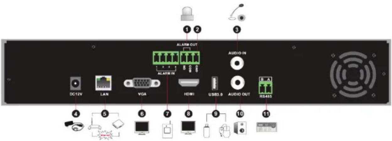
| No. | Name Descriptions | |
| 1 | ALARM OUT | Relay output; connect to external alarm |
| 2 | GND | Grounding |
| 3 | AUDIO IN | Audio input; connect to audio input device, like microphone, pickup, etc |
| 4 | DC12V | DC12V power input |
| 5 | LAN | Network port |
| 6 | VGA | Connect to monitor |
| 7 | ALARM IN | Alarm inputs for connecting sensors |
| 8 | HDMI Connect to high definition display device | |
| 9 | USB Connect USB storage device or USB mouse | |
| 10 | AUDIO OUT | Audio output; connect to sound box |
| 11 | RS485 | Connect to keyboard. A is TX+; B is TX- |

| No. | Name | Descriptions |
| 1 VGA | Connect to monitor | |
| 2 | e-SATA | Connect to HDD with e-SATA interface |
| 3 | RS485 Y/Z interface | Unavailable right now |
| 4 | RS485 A/B interface | Connect to keyboard. A is TX+; B is TX- |
| 5 | AUDIO OUT | Audio output; connect to sound box |
| 6 LAN | Network port | |
| 7 | HDMI | Connect to high definition display device |
| 8 | USB | Connect USB storage device or USB mouse |
| 9 | GND | Grounding |
| 10 | ALARM OUT | Relay output; connect to external alarm |
| 11 | ALARM IN | Alarm inputs for connecting sensors |
| 12 AUDIO IN | Audio input; connect to audio input device, like microphone, pickup, etc | |
| 13 | Power Switch | Press the switch to turn on/off the NVR |
| 14 | Power Supply | Power supply interface |
| No. | Name Descriptions | |
| 1 VGA Connect to monitor | ||
| 2 | RS485 Y/Z interface | Unavailable right now |
| 3 | ALARM OUT | Relay output; connect to external alarm |
| 4 | GND | Grounding |
| 5 | AUDIO OUT | Audio output; connect to sound box |
| 6 | e-SATA1/ e-SATA2 | Connect to HDD with e-SATA interface |
| 7 LAN1/LAN2 Network port | ||
| 8 | HDMI1 | Connect to 4K×2K high definition display device |
| 9 USB3.0/USB | USB3.0 and USB 2.0 interface, connect USB storage device or USB mouse | |
| 10 | HDMI2 | Connect to 1920×1080 high definition display device |
| 11 | RS485 A/B interface | Connect to keyboard. A is TX+; B is TX- |
| 12 | ALARM IN | Alarm inputs for connecting sensors |
| 13 AUDIO IN | Audio input; connect to audio input device, like microphone, pickup, etc | |
| 14 | Power Switch | Press the switch to turn on/off the NVR |
| 15 | Power Supply | Power supply interface |
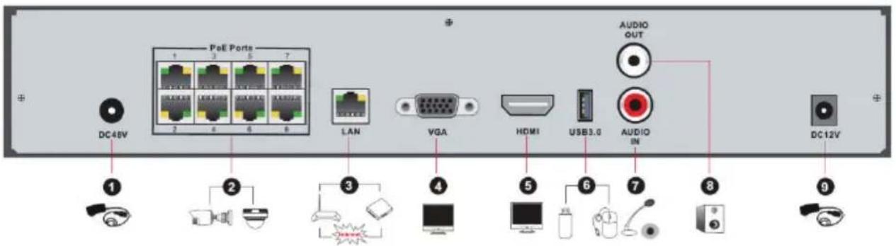
| No. | Name | Descriptions |
| 1 | Power Supply | DC48V power supply interface |
| 2 | PoE port | 8 PoE network ports; connect to 8 PoE IP cameras |
| 3 | LAN | Network port |
| 4 VGA Connect to monitor | ||
| No. | Name Descriptions | |
| 5 | HDMI | Connect to 1920×1080 high definition display device |
| 6 | USB3.0 | USB3.0 interface, connect USB storage device or USB mouse |
| 7 | AUDIO IN | Audio input; connect to audio input device, like microphone, pickup, etc |
| 8 | AUDIO OUT | Audio output; connect to sound box |
| 9 | Power Supply | DC12V power supply interface |
1.5 Connections
- Video Connections
Video Output: Supports VGA/HDMI video output. You can connect to monitor through these video output interfaces simultaneously or independently.
● Audio Connections
Audio Input: Connect to microphone, pickup, etc.
Audio Output: Connect to headphone, sound box or other audio output devices.
- Alarm Connections
Some models may support this function. Take 16 CH alarm inputs and 1 CH alarm output for example.
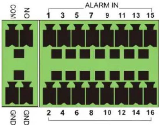
Alarm Input:
Alarm IN 1\~16 are 16 CH alarm input interfaces. There are no type requirements for sensors. NO type and NC type are both available.
The way to connect sensor and the device is as shown below:
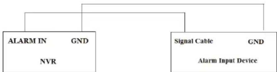
flowchart
graph TD
    A["ALARM IN"] --> B["NVR"]
    C["Signal Cable"] --> D["Alarm Input Device"]
    E["GND"] --> F["ALARM IN"]
    style A fill:#f9f,stroke:#333
    style C fill:#f9f,stroke:#333
    style E fill:#ccf,stroke:#333
The alarm input is an open/closed relay. If the input is not an open/closed relay, please refer to the following connection diagram:

flowchart
graph LR
    A["Alarm (V-output)"] --> B["ALM (+)"]
    A --> C["ALM(-)"]
    B --> D["Relay"]
    C --> D
    D --> E["NVR"]
    E --> F["Switching Value Input"]
    F --> G["IN"]
    F --> H["G"]
Alarm Output:
The way to connect alarm output device:
Pull out the green terminal blocks and loosen the screws in the alarm-out port. Then insert the signal wires of the alarm output devices into the port of NO and COM separately. Finally, tighten the screws. Provided that the external alarm output devices need power supply, you can connect the power supply as per the following figures.

flowchart
graph TD
    A["NVR"] -->|NO| B["Speaker"]
    A -->|COM| C["DC"]
    C --> D["Ground"]
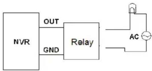
flowchart
graph LR
    A["NVR"] -->|OUT| B["Relay"]
    A -->|GND| B
    B --> C["AC"]
- RS485 Connection
There are two types of RS485 interfaces:

(Type 1)

(Type 2)
Type 1: The P/Z interfaces are unavailable temporarily. K/B interfaces are used to connect keyboard.
Type 2: The RS485 interfaces are used to connect keyboard. A is TX+; B is TX-.
2 Basic Operation Guide
2.1 Startup & Shutdown
Please make sure all the connections are done properly before you power on the unit. Proper startup and shutdown are crucial to expending the life of your device.
2.1.1 Startup
□ Connect the output display device to the VGA/HDMI interface of the NVR.
□ Connect the mouse and power. The device will boot and the power LED will turn blue.
☐ A WIZARD window will pop up (you should select the display language the first time you use the NVR). Refer to 3.1 Startup Wizard for details.
2.1.2 Shutdown
You can power off the device by using remote control or mouse.
By remote controller:
☐ Press Power button. This will take you to a shutdown window. The unit will power off by clicking "OK" button.
□ Disconnect the power.
By mouse:
☐ Click Start→Shutdown to pop up the Shutdown window. Select “Shutdown” in the window. The unit will power off by clicking “OK” button.
□ Disconnect the power.
2.2 Remote Control
□ Two AAA size batteries.
Open the battery cover of the remote control.
Place batteries. Please observe the polarity (+ and -).
□ Replace the battery cover.
Key points to check in case the remote doesn't work.
- Check batteries polarity.
- Check the remaining charge in the batteries.
- Check IR controller sensor for any blockage.
| Button Function | ||
| Power Button | Switch off—to stop the device | |
| Record Button To start recording | ||
| -/-- /0-9 | Input number or choose camera | |
| Fn1 Button | Future Use | |
| Multi Button | To choose multi screen display mode | |
| Next Button | To switch the live image | |

| SEQ | To go to sequence view mode |
| Audio | To enable audio output in live mode |
| Switch Future Use | |
| Direction button | To move cursor in setup or pan/tilt PTZ |
| Enter Button To confirm the choice or setup | |
| Menu Button To go to menu | |
| Exit Button To exit the current interface | |
| Focus/IRIS/Zoom/PTZ | To control PTZ camera |
| Preset Button To enter into preset setting in PTZ mode | |
| Cruise Button | To go to cruise setting in PTZ mode |
| Track Button Future Use | |
| Wiper Button Future Use | |
| Light Button Future Use | |
| Clear Button Future Use | |
| Fn2 Button | Future Use |
| Info Button | Get information about the device |
| To control playback. Play(Pause)/Stop/Previous Frame/Next Frame/Speed Down/Speed Up | |
| Snap Button To take snapshots manually | |
| Search Button | To go to search mode |
| Cut Button | Future Use |
| Backup Button To go to backup mode | |
| Zoom Button | To zoom in the images |
| PIP Button Future Use | |

| Button Function | |
| REC Record manually | |
| Search To enter search mode | |
| MEUN To enter menu | |
| Exit To exit the current interface | |
| ENTER | To confirm the choice or setup |
| Direction button To move cursor in setup | |
| ZOOM To zoom in | |
| PIP Future Use | |
 | To control playback. Play(Pause)/Next Frame/Speed Up/Stop/Previous Frame/Speed Down |
| Multi To choose multi screen display mode | |
| Next To switch the live image | |
| SEQ | To go to sequence view mode |
| INFO | Get information about the device |
2.3 Mouse Control
Mouse control in Live & Playback interface
In the live & playback interface, double click on any camera window to show the window in single screen mode; double click the window again to restore it to the previous size.
In the live & playback interface, if the interfaces display is in full screen, move the mouse to the bottom of the interface to pop up the tool bar. The tool bar will disappear automatically after you move the mouse away from it; move the mouse to the right side of the interface to pop up a panel and the panel will disappear automatically after you move the mouse away from it.
Mouse control in text-input
Move the mouse to the text-input box and then click the box. The input keyboard will pop up automatically.
Note: Mouse is the default tool for all operations unless an exception is indicated.
2.4 Text-input Instruction

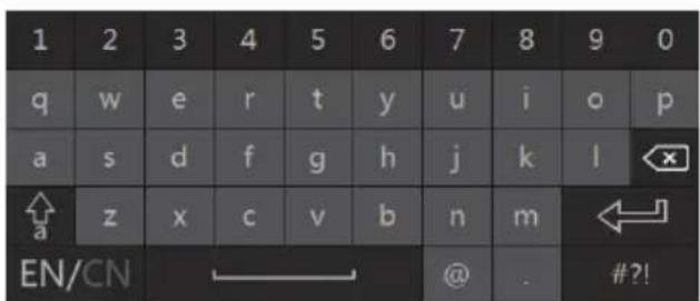
The system includes two input boxes. Refer to the above pictures. The left box is the number input box and the right box is the input box which provides inputs of numbers, letters and punctuation characters. The introductions of keys on the input boxes are shown below.
| Button | Meaning | Button | Meaning |
 | Backspace key |  | Switch key of punctuation character |
 | Delete Key |  | Enter key |
 | Switch key between upper and lower letter |  | Space key |
 | Switch key of language | ||
2.5 Common Button Operation
| Button Meaning | ||
 | Click it to show the menu list. | |
 | Click it to change the sequence of the list. | |
 | Click it to change the camera displaying mode. | |
 | Click it to close the current interface. | |
 | Click it to go to the earliest date of camera recording. | |
 | Click it to go to the latest date of camera recording. | |
3 Wizard & Main Interface
3.1 Startup Wizard
The disk icons will be shown on the top of the startup interface. You can view the number and status of each disk quickly and conveniently through these icons (☐: no disk; ☐: unavailable disk; ☑: RW available disk).
You can quickly configure the NVR by the wizard setup. You must configure the wizard when you start the NVR for the first time (or click "Skip" to cancel the wizard next time).

Click "Wizard Setup" to start wizard. The setting steps are as follows.
☐ System Login. Set your own password or use the default when you use the wizard for the first time (the default username of the system is admin and the default password of admin is 123456); select the login username and enter the corresponding password next time.
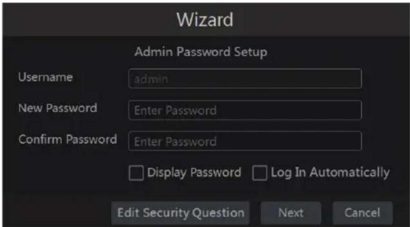
Click “Edit Security Question” to set questions and answers for password security of admin. If you forget the password, please refer to Q4 in Appendix A FAQ for details.
Click "Next" to continue or click "Cancel" to exit the wizard.
☐ Date and Time Configuration. The date and time of the system needs to be set up if you use the wizard for the first time. Refer to the following figure. Set the time zone, system time, date format and time format. The DST will be enabled by default if the time zone selected includes DST. Click “Next” to continue.

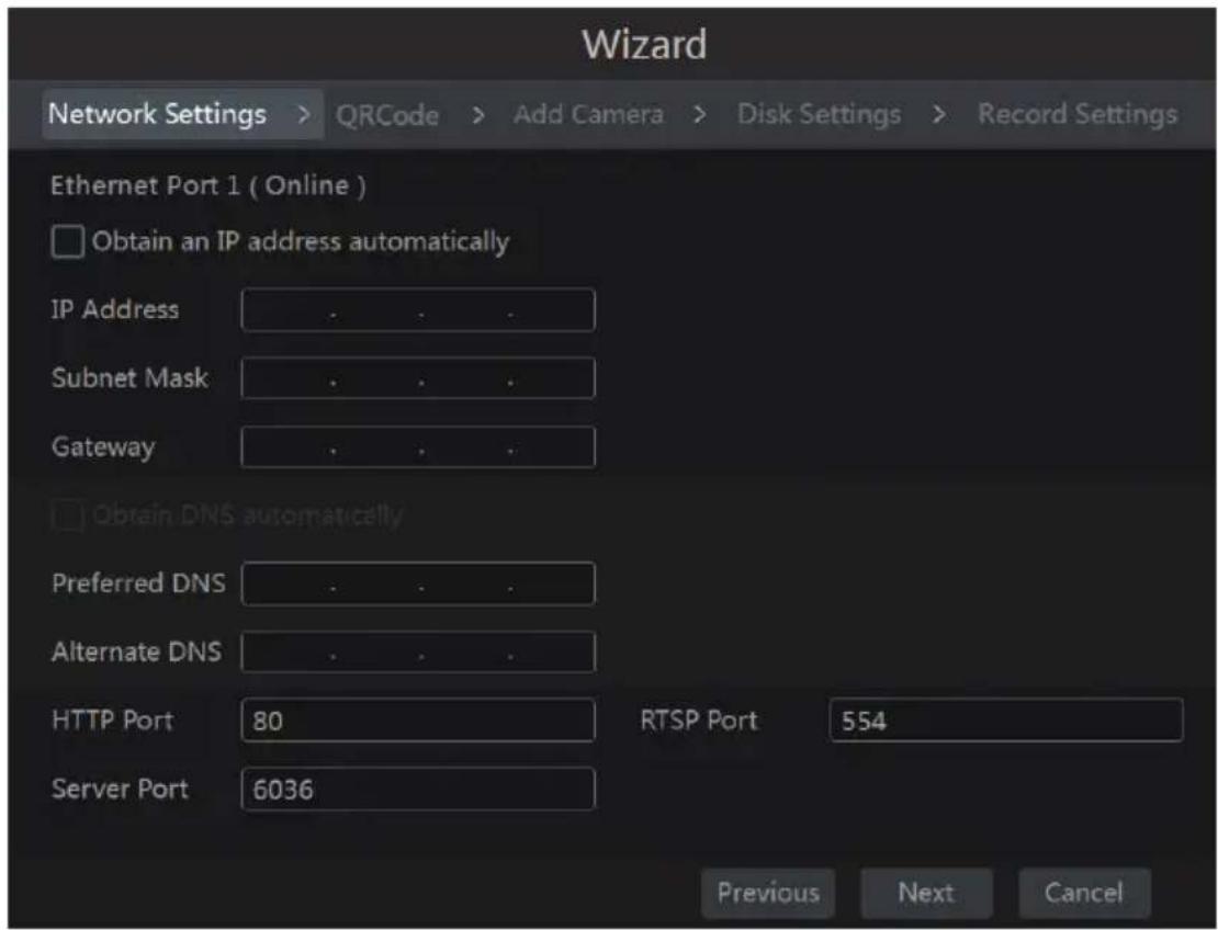
☐ Network Settings. Check “Obtain an IP address automatically” and “Obtain DNS automatically” to get the IP address and DNS automatically (the DHCP function of the router in the same LAN should also be enabled), or manually input them. Input the HTTP port, RTSP port and Server port (please see 11.1.2 Port Configuration for details). Click “Next” to continue.
Note:
If you use the NVR with the PoE network ports, the online state of the internal Ethernet port will be shown on the interface. Refer to the picture below. Please refer to 11.1.1 TCP/IPv4 Configuration for detail introduction of the internal Ethernet port.

☐ QRCode. You can scan the QRCode through the mobile client which is installed on a mobile phone or Tablet to log into the mobile client instantly. Please refer to 12.1 Mobile Client Surveillance for details.
☐ Add Camera. Click “Refresh” to refresh the list of online IP cameras which are in the same local network with NVR and then click + to add the searched camera. Click “Add All” to add all the cameras in the list. Click 📋 to delete the added camera. Click “Delete All” to delete all the added cameras.
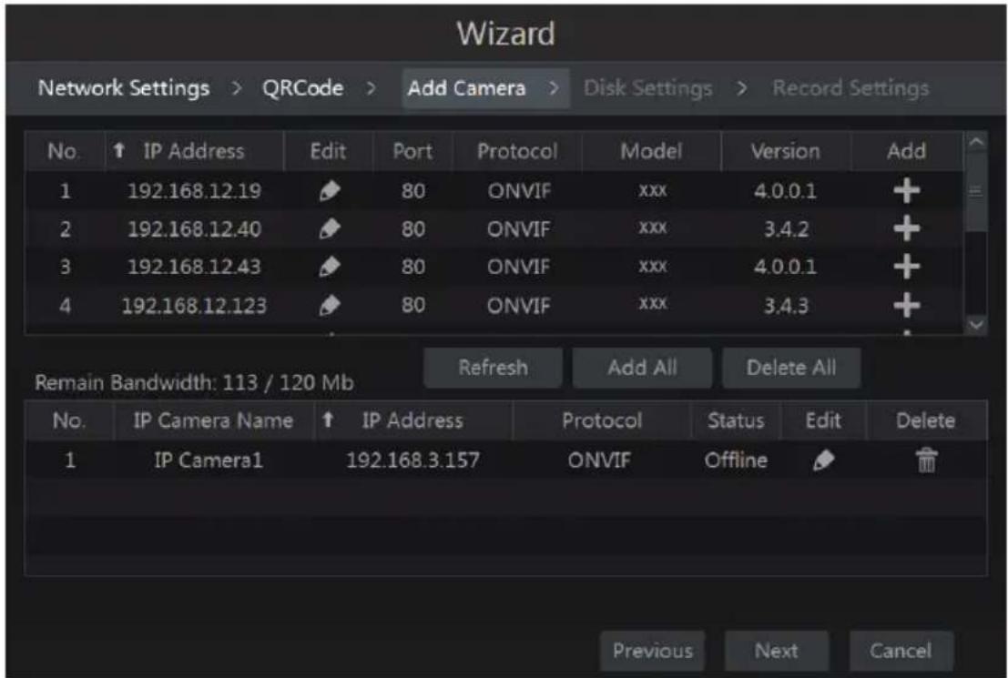
Click 📋 to edit the found IP camera as shown on the below left. Input the new IP address, subnet mask, gateway, username and the password of the camera. Click “OK” to save the settings.

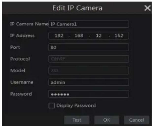
Click to edit the added camera as shown on the above right. Input the new camera name, IP address, port, username and the password of the camera. You can click "Test" to test the effectiveness of the input information. Click "OK" to save the settings. You can change the IP camera name only when the added camera is online. Click "Next" to continue.
☐ Disk Settings. You can view the disk number, disk capacity of the NVR and serial number,
R&W status of the disk. Click "Formatting" to format the disk. Click "Next" to continue.
Record Settings. Two record modes are available: auto and manual.
Auto: Select one auto mode in the interface as shown below and then click "OK" button to save the settings. See 7.1.1 Mode Configuration for details.
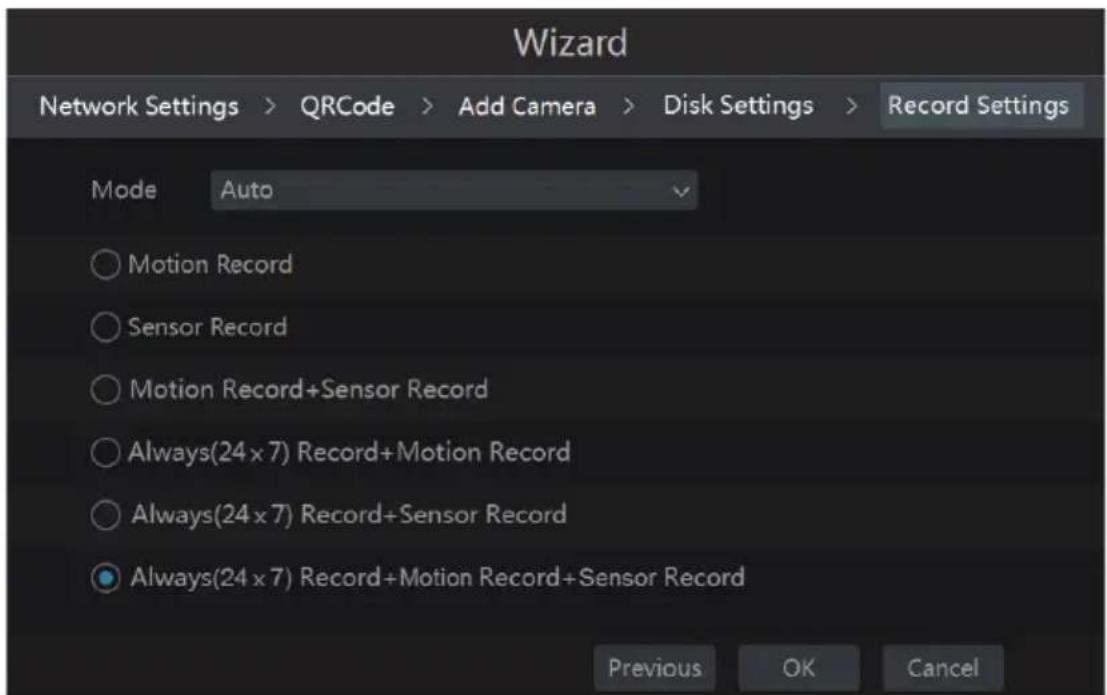
Manual: Set the “Sensor Record”, “Motion Record” and “Schedule Record” of each camera. Click “OK” to save the settings. See 7.1.1 Mode Configuration for details.

3.2 Main Interface
3.2.1 Main Interface Introduction
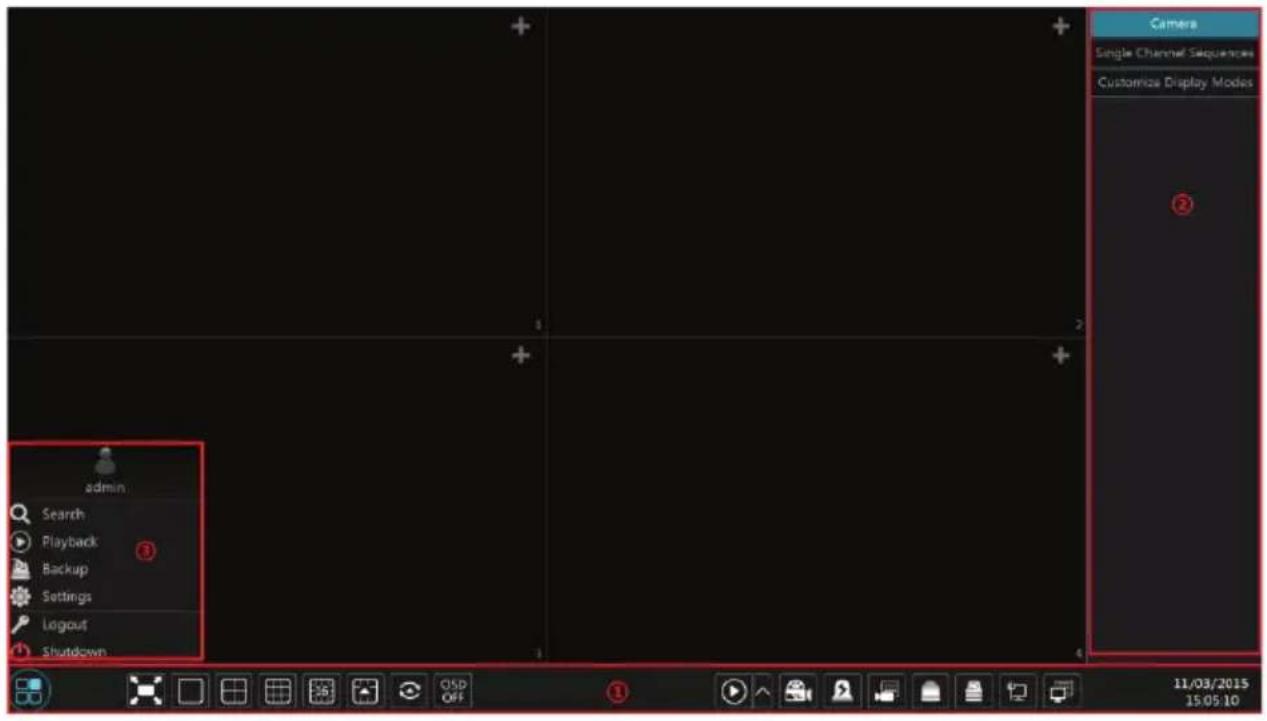
The buttons in area □ are introduced in the table below.
| Button Meaning | ||
 | Start button. Click to pop up area 3. | |
 | Full screen button. Click to show full screen; click again to exit the full screen. | |
 | Screen mode button. | |
 | Dwell button (see 5.2.2 Quick Sequence View and 5.2.4 Scheme View In Sequence for details). | |
 | Click to enable OSD; click [IMAGE] to disable OSD. | |
 | Click ↑ to set the default playback time before starting instant playback (8.1 Instant Playback) or going to the playback interface for playback operations (8.2 Playback Interface Introduction); click [IMAGE] to go to the playback interface. For instance, if you choose “5 minutes ago” as the default playback time, you can playback the recording from the past five minutes. | |
 | Manual record button. Click to enable/disable record. | |
 | Manual alarm button. Click to trigger or clear the alarm-out manually in the popup window. | |
 | Record status button. Click it to view the record status. | |
 | Alarm status button. Click it to view the alarm status. | |
 | Disk status button. Click it to view the disk status and RAID status. | |
| [WS8W] | Network status button. Click it to view the network status. | |
 | Information button. Click it to view system information. | |
Introduction of area :
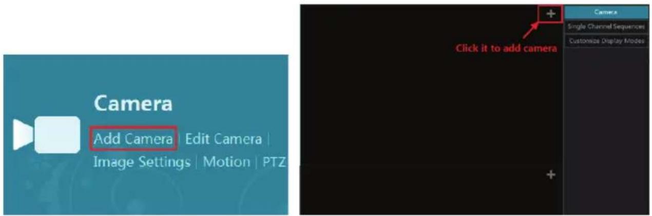
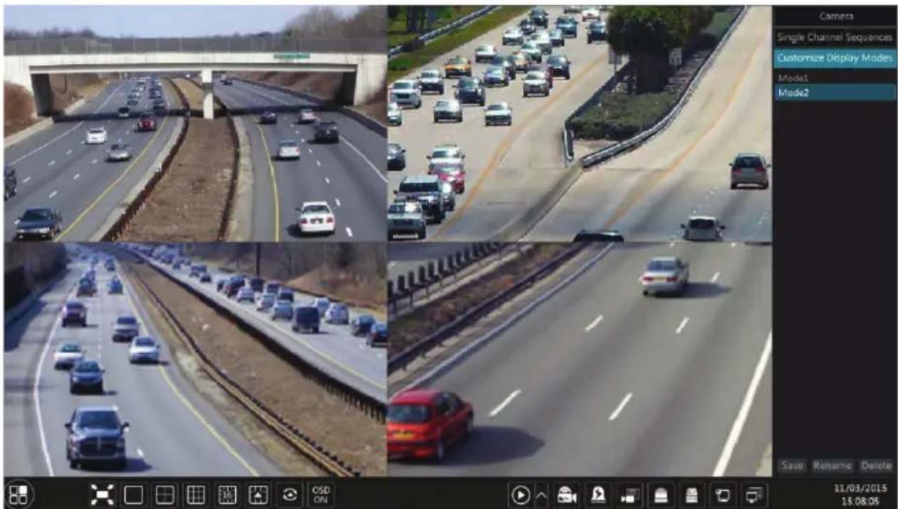
Click “Camera” to view all the added cameras in the camera list. Select one camera window on the left side of the interface and then double click one camera in the list to preview the camera image in the selected window.
Click “Single Channel Sequences” to view all the added groups in the group list; click one group in the list to view all the added cameras in the group (refer to 4.2 Add/Edit Camera Group for detail configuration of the camera group). Select one camera window on the left side of the interface and then double click one group in the group list to preview the cameras’ images one by one in the selected window.
Click “Customize Display Modes” to view all the display modes in the display mode list (refer to 5.2.1 Preview By Display Mode for detail configuration of the display mode). Double click one display mode in the list to switch to the display mode for previewing.
Introduction of area ③:
| Icon / Button Meaning | |
 | It shows the current login user. |
 | Click it to go to record search interface, see 8.3 Record Search & Playback for details. |
 | Click it to go to playback interface (click ↑ on the tool bar at the bottom of the live preview interface to set the default playback time), see 8.2 Playback Interface Introduction for details. |
 | Click it to go to backup interface, see 8.4 Backup for details. |
 | Click it to pop up the setup panel, see 3.2.2 Setup Panel for details. |
 | Click it to log out the system. |
 | Click it and then select “Logout”, “Reboot” or “Shutdown” in the popup window. |
3.2.2 Setup Panel
Click Start→Settings to pop up the setup panel as shown below.
![Camera Add Camera Edit Camera Image Settings Motion INT2 Record Encode Parameters | Record Schedule Advanced Alarm Sensor Alarm Alarm Out Motion Alarm Disk Disk Management Storage Mode Disk Network TOPSIA EONS Post Email Network Status Account and Authority Add User Edit User Edit Permission Group Modify Password System Basic [ Data and Time ] Information | Voting [ Backup and Bindue ] admin Search Playback Backup Settings Logout Shutdown 11/03/2015 15:05:13](/content/2026/06/1213934/images/bf2e0d0f31431cdee4a97f189a6bd59278e151e9a7f0e8ac307c8d2a754795d6.jpg)
The setup panel includes seven modules. Each module provides some function entries with links for convenient operation.
Here we take Camera module as an example. The Camera module provides convenient links such as “Add Camera”, “Edit Camera”, “Image Settings”, “Motion” and “PTZ”. Click Camera to go to the camera management interface as shown below.
There are some function items on the left side of the camera management interface. Click each item to go to corresponding interface or window. For instance, click “Add Camera” to pop up the window as shown below.
Click the main menus on the top of the camera management interface to go to corresponding interfaces. Refer to the picture below. For instance, you can go to system setup interface by clicking "System" tag.
Live Display Camera Record Alarm Disk Network Account and Authority System
3.2.3 Main Functions
Camera
The module covers the functions such as Camera Management (see Chapter 4 Camera Management for details), Image Settings (see 5.3 Preview Image Configuration for details), Motion (see 9.2.1 Motion Configuration for details) and PTZ (see Chapter 6 PTZ for details).
Record
The module covers the functions such as Encode Parameters and Record Schedule. Please see Chapter 7 Record & Disk Management for details.
Disk
The module covers the functions such as Disk Management, Storage Mode and Disk Information. Please see Chapter 7 Record & Disk Management for details.
> Alarm
The module covers the functions such as Sensor and Motion Alarm Handling and Alarm Out Settings. Please see Chapter 9 Alarm Management for details.
Network
The module covers the functions such as TCP/IPv4, DDNS, Port, E-mail and Network Status. Please see 11.1 Network Configuration for details.
Account and Authority
The module covers the functions such as Account Management (see 10.1 Account
Management for details) and Permission Management (see 10.3 Permission Management for details).
System
The module covers the functions such as Basic Configuration (see 11.2 Basic Configuration for details), Device Information (see 11.7 View System Information for details), Log Information (see 11.6 View Log for details) and Configuration File Import&Export (see 11.5 Backup and Restore for details).
4 Camera Management
4.1 Add/Edit Camera
4.1.1 Add Camera
The network of the NVR should be set before adding IP cameras (see 11.1.1 TCP/IPv4 Configuration for details).
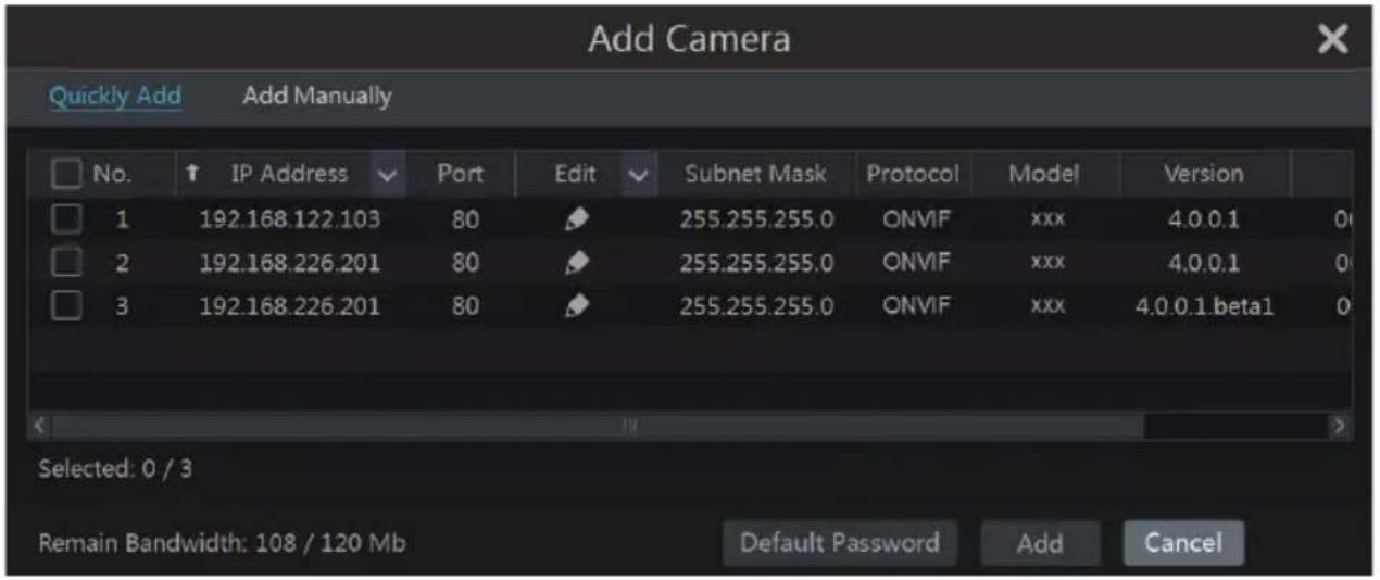
Refer to the pictures below. Click Add Camera in the setup panel or 🎨 in the top right corner of the preview window to pop up the “Add Camera” window as shown below. You can quickly add or add the IP camera manually.
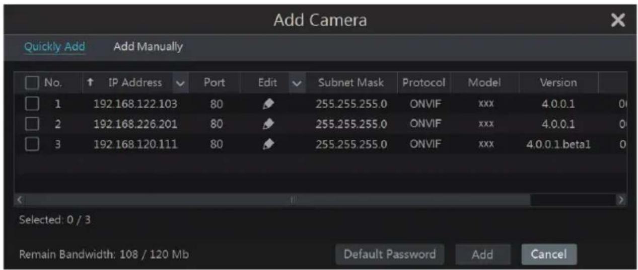
▶ Quickly Add
Check the cameras and then click “Add” to add cameras. Click 📋 to edit the camera’s IP address, username and password. Click “Default Password” to set the default username and password of each camera.
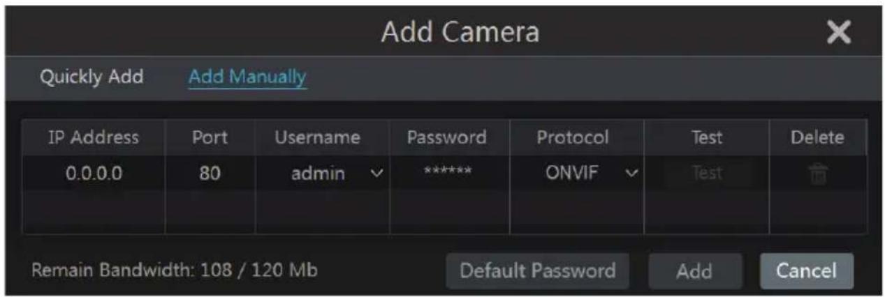
Add Manually
Input the IP address, port, username and password of the camera and then select the protocol. Click “Test” to test the effectiveness of the input information and then click “Add” button (you can input one camera’s information or above such as IP address, username and password before clicking “Add” button). Click 📄 to delete the camera. Click “Default Password” to set the default username and password of each camera.
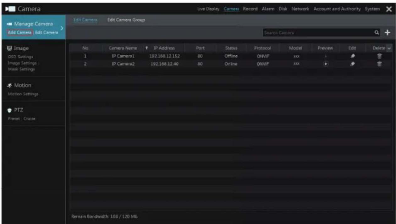
4.1.2 Edit Camera
Click “Edit Camera” in the setup panel to go to the interface as shown below. Click to view the live image of the camera in a popup window. Click to edit the camera (see Add camera in 3.1Startup Wizard for details). Click to delete the camera.

Note:
If you use the NVR with PoE network ports, the IP cameras (with PoE function) which directly connect to the PoE port of the NVR will be displayed automatically in the camera list. Refer to the picture below. The IP camera's which occupies the PoE resource has a prefix shown before its camera name. The prefix consists of PoE plus PoE port number. The IP cameras which connect to the PoE ports cannot be deleted from the camera list manually.
![Edit Camera Edit Camera Group Search Camera + No. Camera Name ↑ IP Address Port Status Protocol Model Preview Edit Delete 1 [POE3]IP Camera1 10.151.151.20 80 Online ONVIF xxx ▶ ↻ 2 IP Camera2 192.168.12.40 80 Online ONVIF xxx ▶ ↻ ↺ 3 IP Camera3 192.168.12.152 80 Online ONVIF xxx ▶ ↻ ↺ 4 IP Camera4 192.168.12.41 80 Online ONVIF xxx ▶ ↻ ↺ 5 IP Camera5 192.168.12.153 80 Offline ONVIF xxx ▶ ↻ ↺ 6 IP Camera6 192.168.12.154 80 Online ONVIF xxx ▶ ↻ ↺ 7 IP Camera7 192.168.12.155 80 Online ONVIF xxx ▶ ↻ ↺ 8 IP Camera8 192.168.12.156 80 Online ONVIF xxx ▶ ↻ ↺ 9 IP Camera9 192.168.12.157 80 Online ONVIF xxx ▶ ↻ ↺ 10 [POE1]IP Camera10 192.168.12.158 80 Online ONVIF xxx ▶ ↻ ↺ Remain Bandwidth: 60 / 120 Mb](/content/2026/06/1213934/images/373b0a8bb2afe91c237d7fc8511bf7530a272fe41e04bd6be0bcd9a4bfe80ba7.jpg)
- The IP camera which directly connects to the PoE port of the NVR through private protocol will be shown automatically in the camera list.
- One of the two conditions must be met if the IP camera which directly connects to the PoE port of the NVR through ONVIF protocol should be shown automatically in the camera list.
√ The IP camera which directly connects to the PoE port is in the same network segment with the internal Ethernet port.
√ The DHCP (obtain an IP address automatically) of the IP camera which directly connects to the PoE port is enabled.
If the IP camera which connects to the PoE port cannot be displayed automatically in the camera list, please refer to Q6 in Appendix A FAQ for details.
4.2 Add/Edit Camera Group
4.2.1 Add Camera Group
Click "Edit Camera Group" in the above interface to go to the interface as shown below.
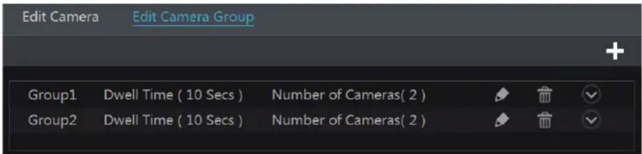
Click + to pop up the window as shown below. Set the group name and dwell time (the dwell time of the camera group sequence view) in the window. Check the cameras and then click “Add” to add group. Click √ to view the cameras in the group after adding group.
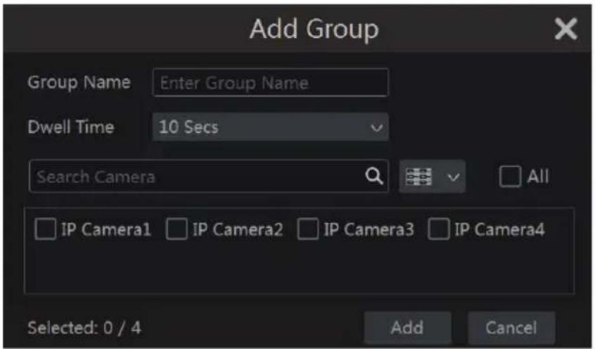
4.2.2 Edit Camera Group
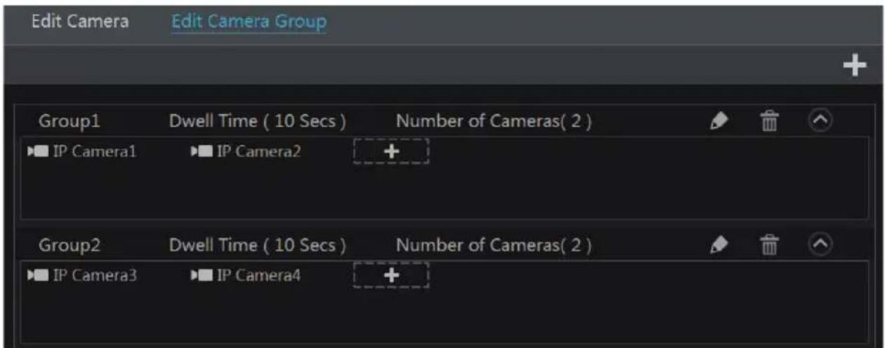
Click 📋 to modify the group information such as group name and dwell time. Click to delete the group.

5 Live Preview Introduction
5.1 Preview Interface Introduction
You should add cameras first after logging on to the system (see 4.1.1 Add Camera for details). Refer to the interface as shown below, drag one camera in the preview window to another window for camera window exchanging.
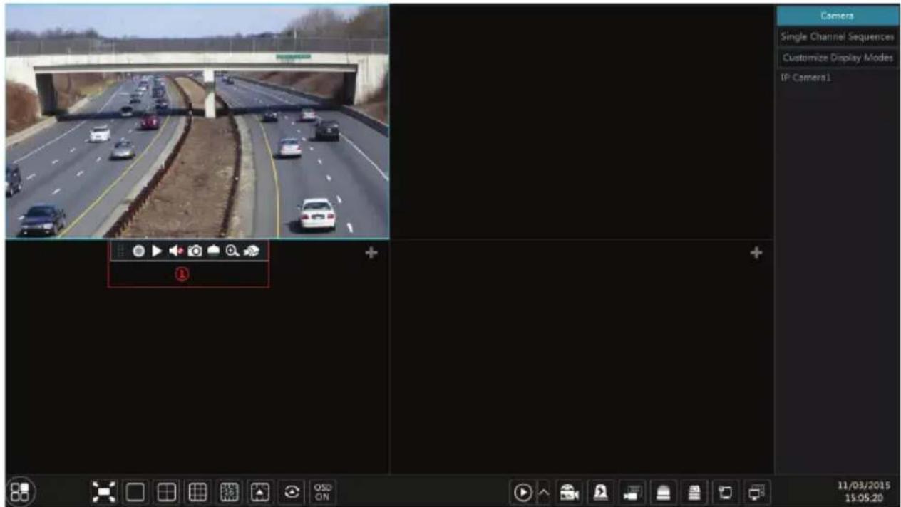
Click the preview window to show the tool bar as shown in area □; right click the preview window to show the menu list. The tool bar and menu list are introduced in the table below.
| Button | Menu List | Meaning |
 | -- | Move tool. Click it to move the tool bar anywhere. |
 | Manually Record On | Click to start recording. |
 | Instant Playback | Click ▶ to playback the record; click “Instant Playback” to select or self-define the instant playback time. See 8.1 Instant Playback for details. |
 | Enable Audio | Click to enable audio. You can listen to the camera audio by enabling audio. |
 | Snap | Click to pop up the snapshot window. Click “Save” in the window to save the image. Click “Export” to export the image. |
 | PTZ Control | Click to go to PTZ control interface. See Chapter 6 PTZ for details. |
 | Zoom In | Click to go to single channel zoom interface. |
 | -- | Click to go to image adjustment interface. Refer to 5.3.4 Image Adjustment for details. |
| -- | Camera Info | Right Click to view the camera information. |
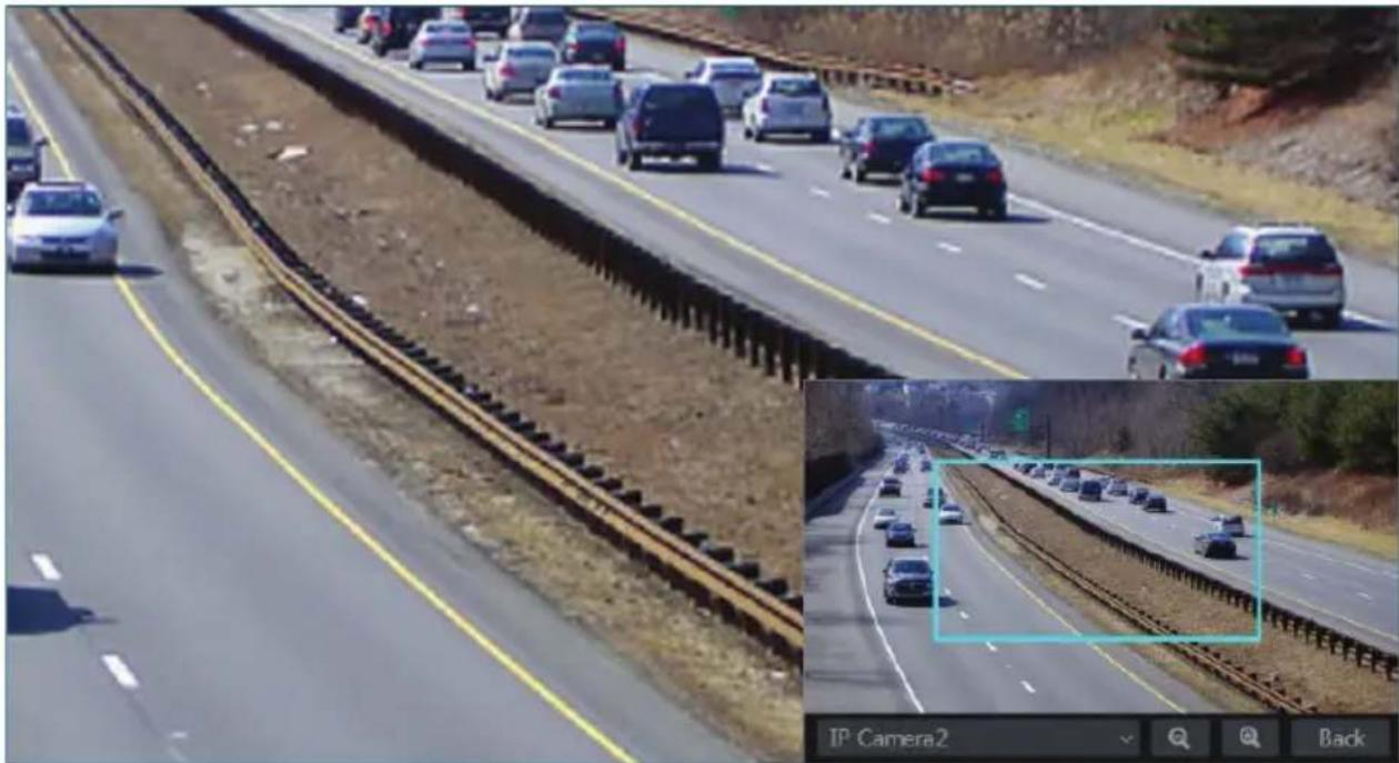
The single channel zoom interface is as shown below. Press and drag the blue box to select the zoom area. Click / to zoom the image. Click the camera selection box to select other cameras for zoom. Click “Back” to return to the live preview interface.
natural_image
Highway traffic scene with multiple cars on elevated tracks and a close-up inset showing a detailed lane detail (no visible text or symbols)5.2 Preview Mode
5.2.1 Preview By Display Mode
Set different screen modes and camera display sequences as required and then save the display modes, priorities and so on. Refer to the picture below. Double click one display mode in the display mode list to view the live images in this mode.
➢ Add Display Mode
Method One:
☐ Click “Customize Display Modes” in the above interface and then set the screen mode.
☐ Add the cameras and adjust the cameras display sequence as required.
☐ Click “Save” button under the display mode list and then enter the display mode name in the popup window, click “OK” button to save the current display mode.
Method Two:
☐ Click Start→Settings→System→Basic→Output Settings to go to the interface and then set the screen mode.
☐ Double click the camera or camera group in the list to add them to the selected window.
☐ Click ★ to save the current display mode (refer to 5.2.4 Scheme View In Sequence for detail configurations). The display mode will be saved and displayed in the display mode list in the live preview interface.
Edit Display Mode
Click “Customize Display Modes” tab in the live preview interface and then select one display mode in the list. Click “Rename” to edit the display mode name; click “Delete” to delete the display mode.
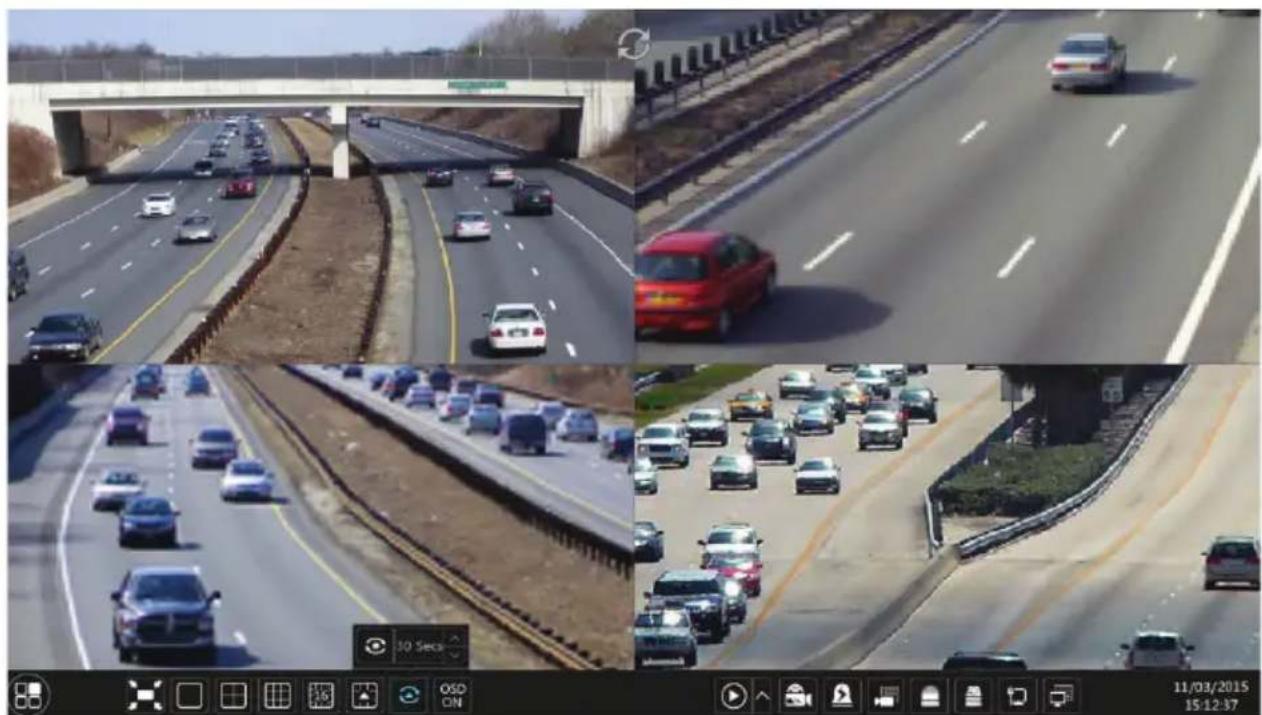
5.2.2 Quick Sequence View
You can start quick sequence view if the scheme has not been created. If the scheme has been created, please refer to 5.2.4 Scheme View in Sequence for details.
natural_image
Four-panel composite image showing highway traffic scenes: elevated overpass, multi-lane highway, and multi-lane highway with vehicles (no visible text or symbols)Go to the live preview interface and then click 📄 to pop up a little window. Set the dwell time in the window and then click 📋 to view the live group by group according to the camera number of the current screen mode. Double click the sequence view interface to pause the view; double click again to restore the view. Click 🔒 to stop the view.
5.2.3 Camera Group View In Sequence
You can start camera group view in sequence if camera group has been created (see 4.2.1 Add
Camera Group for details).
☐ Go to the live preview interface and then select a camera window.

☐ Double click one camera group on the right side of the interface. The cameras in the group will start camera group view one by one in the selected camera window.
You can also drag the group directly to any preview window. Right click on the group view window and then click “Close Dwell” button to stop the view.
5.2.4 Scheme View In Sequence
Click Start→Settings→System→Basic→Output Settings to go to the interface as shown below. Area □ displays all the dwell schemes; area □ shows the detailed information of the scheme; area □ displays all the cameras and groups; area □ is the tool bar (☐: clear button; ★: favorite button, click it to pop up a window, enter the display mode name in the window and then click “OK” to save the current display mode; other buttons are screen mode buttons).

Add Scheme
Click + in area □ to create a new scheme. Click ✗ on the top right corner of the scheme to delete it.
Configure Scheme
a) Select a scheme in area □ and then click the screen mode button on the tool bar to set the screen mode of the scheme.
b) Select a camera window in area □ and then double click the camera or group in area □. The camera or group will be added into the selected window. One camera in the same scheme cannot repeat. You can click the right-click menu “Clear” in area □ to remove a single camera or click □ remove all the cameras.
c) Click "Apply" to save the settings.
Start Sequence View
Go to live preview interface and then click 🔒 to pop up a window. Set the dwell time in the window and then click 🔒 to start scheme view in sequence. Double click the sequence view interface to pause the view; double click again to restore the view. Click 🔒 to stop the view.
5.3 Preview Image Configuration
5.3.1 OSD Settings
Click Start→Settings→Camera→Image→OSD Settings to go to the interface as shown below. Select the camera, input the camera name (or double click the camera name in the camera list to change the camera name), enable or disable the name and time OSD (if enabled, drag the red name and time OSD directly in the image view area to change the OSDs' display position) and
select the date and time formats. Click "Apply" to save the settings.

5.3.2 Image Settings
Click Start→Settings→Camera→Image→Image Settings to go to the following interface. Select the camera and then set the brightness, contrast, saturation and hue of the camera. You can click “Default” button to restore the image settings to the default factory settings.

5.3.3 Mask Settings
Some areas of the image can be masked for privacy. Up to four mask areas can be set for each camera. Click Start→Settings→Camera→Image→Mask Settings to go to the interface as shown below. Select the camera and enable the mask. Click “Draw” button and then drag the mouse on the image area to set the mask area; click “Delete” button to delete the mask areas; click “Apply” to save the settings.

5.3.4 Image Adjustment
Go to live preview interface and then click 📋 button on the tool bar under the camera window to go to the image adjustment interface.

➢ Image Adjustment
Select the camera and then click “Image Adjustment” to go to image adjustment tab. Refer to the above picture. Drag the slider to set the camera’s brightness, contrast, saturation and hue value. Check sharpen, wide dynamic and denoise and then drag the slider to set the value. Click “Default” button to set these parameters to default values.
The introductions of these parameters are as follows:
| Parameter Meaning | |
| Brightness The brightness level of the camera's image. | |
| Contrast | The color difference between the brightest and darkest parts. |
| Saturation | The intensity of the colors |
| Hue Adjust the shade of the colors | |
| Sharpen | Sharpen edges in the image, to high of setting will create more noise in image |
| Wide Dynamic | Wide Dynamic Range (WDR) function helps the camera provide clear images even under extreme backlight circumstances. When there are both very bright and very dark areas simultaneously in the field of view, WDR balances the brightness level of the whole image and provide clear images with details. |
| Denoise | Adopts noise reduction technology to decrease the noise level and makes the image more thorough. Increasing the value will make the noise reduction effect better but it will reduce the image resolution. |
| White Balance | White balance is the process of calibrating your camera to show colors accurately under varying light conditions |
| Image Mirror | Reverse the current video image right and left. |
| Image Flip Turn | the current video image upside down. |
➢ Lens Control (camera dependent)
Select the camera and then click “Lens Control” to go to lens control tab. Click - or + to adjust the zoom and focus parameters of the camera’s lens. Click “Save” to save the settings.

natural_image
Highway with multiple cars and elevated overpass under a partly cloudy sky (no visible text or symbols)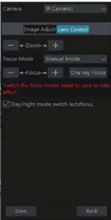
The introductions of these parameters and buttons are as follows:
| Button/Parameter Meaning | |
 | Click  to zoom in/out the image. to zoom in/out the image. |
| Focus Mode | If manual mode is selected, focus button & “One Key Focus” & “Day/night mode switch autofocus” will be available; if auto mode is selected, the time interval setup will be available. |
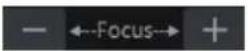 | Click  to increase/decrease the focal length. to increase/decrease the focal length. |
 | Click to focus automatically . |
| Day/night mode switch autofocus | If checked, the lens will focus automatically when the camera is switching day/night mode. |
| Time Interval | It is the time interval when camera lens is auto-focusing. The interval can be set in the drop-down list. |
Note: This function is only available for the models with auto varifocal lens, or the settings here are ineffective
6 PTZ
6.1 PTZ Control Interface Introduction
Click ☐ on the tool bar at the bottom of the live preview window to go to the PTZ control interface as shown below. You can select another IP dome or PTZ IP camera on the top right of the interface for PTZ control.

Introductions of the buttons on the bottom right of the interface:
| Button Meaning | |
 | Click  t t |
 | Click  |
 | Click  |
 | Click  |
 | Drag the slider to adjust the rotating speed of the dome. |
 | Click  |
 | Click  |
| [A0X8] | Click it to return to the live preview interface. |
▶ Analog Joystick Control
The analog joystick on the left side of the interface provides quick PTZ control. The dome or PTZ will rotate when you drag the analog joystick. The farther you drag the analog joystick from the middle of the image, the faster the dome or PTZ rotates. The dome or PTZ will stop rotating when you stop dragging the analog joystick.
3D Control
Click the camera image on any area and then the image will be centered on the clicked point. Refer to the picture as shown below. Drag the mouse from A to B to get a green rectangle and the rectangle area will be zoomed in.


Refer to the picture as shown below. Drag the mouse from C to D to get a green rectangle and the rectangle area will be zoomed out.

▶ Advanced 3D Control
Double click the left button of the mouse on any area of the camera image and then the image size will be doubled and centered on the clicked point.
Press and hold the left button of the mouse on any area of the camera image to zoom in the image; press and hold the right button to zoom out the image.
Move the cursor of the mouse to the camera image and then slide the scroll wheel of the mouse forward to zoom in the image, slide the scroll wheel of the mouse backward to zoom out the image.
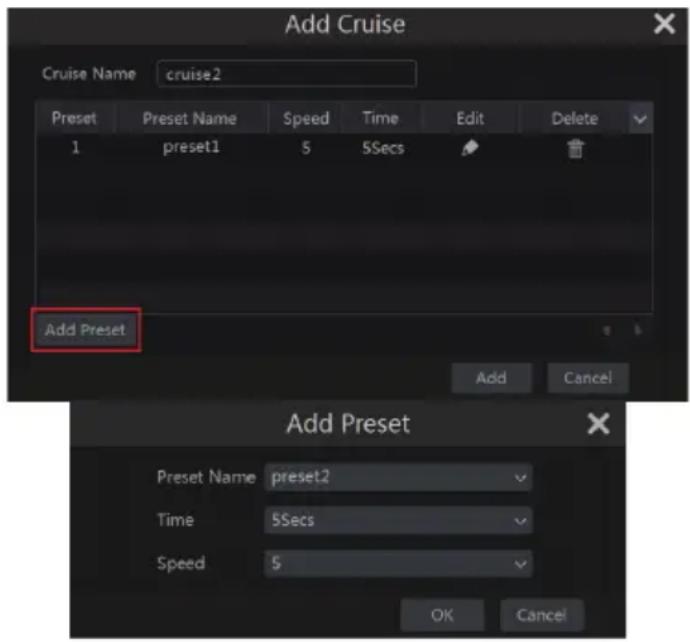
Preset Setting
Click “Preset” to go to preset operation tab and then click “Add” button to pop up a window as shown below. Select the preset and then input the preset name in the window; finally click “OK” button to save the settings. You can add 255 presets for each dome.
Adjust the dome's direction and then click "Save Position" to save the current preset position (you can also click another preset in the preset list and then save the preset position after adjusting the dome's direction); click 📋 in the preset list to call the preset; click "Delete" button to delete the selected preset.
You can also go to preset setting interface for preset setting, see 6.2 Preset Setting for details.
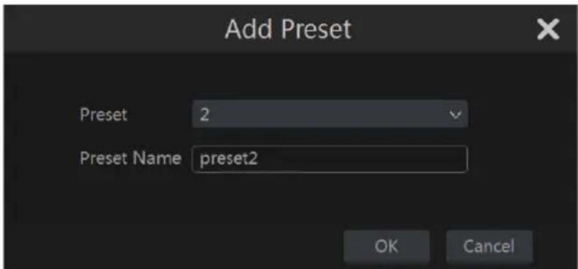
Cruise Setting
Click “Cruise” to go to cruise operation tab and then click “Add” button to pop up a window as shown below left. You can add 8 cruises for each dome at most.
☐ Input the cruise name in the “Add Cruise” window and then click “Add preset” to pop up the “Add Preset” window (Before adding preset to the cruise, please add preset of the dome first).
In the “Add Preset” window, select the preset name, preset time and preset speed and then click “OK” button.
☐ In the “Add Cruise” window, you can click 📋 to reselect the preset, then change the preset time and speed. Click 📋 to delete the preset. Click “Add” button to save the cruise.
Click ▶ to start the cruise and click □ to stop the cruise in the cruise list of the cruise operation tab; click “Delete” button to delete the selected cruise.
You can also go to cruise setting interface for cruise setting, see 6.3 Cruise Setting for details.
6.2 Preset Setting
Click Start→Settings→Camera→PTZ→Preset to go to the interface as shown below.
▶ Add preset
Select camera and then click “Add” button to add preset; or click in the camera list on the right side of the interface to display the preset information of the dome and then click to add preset. The operations of the “Add Preset” window are similar to that of the PTZ control interface; please see 6.1 PTZ Control Interface Introduction for details.
Edit preset
Select camera and preset. You can input the new name of the preset and then click to save the new preset name. Adjust the rotating speed, position, zoom, focus and iris of the preset and then click "Save Position" to save the preset.
Delete Preset
Select camera and preset and then click "Delete" to delete the preset.
6.3 Cruise Setting
Click Start→Settings→Camera→PTZ→Cruise to go to the interface as shown below.
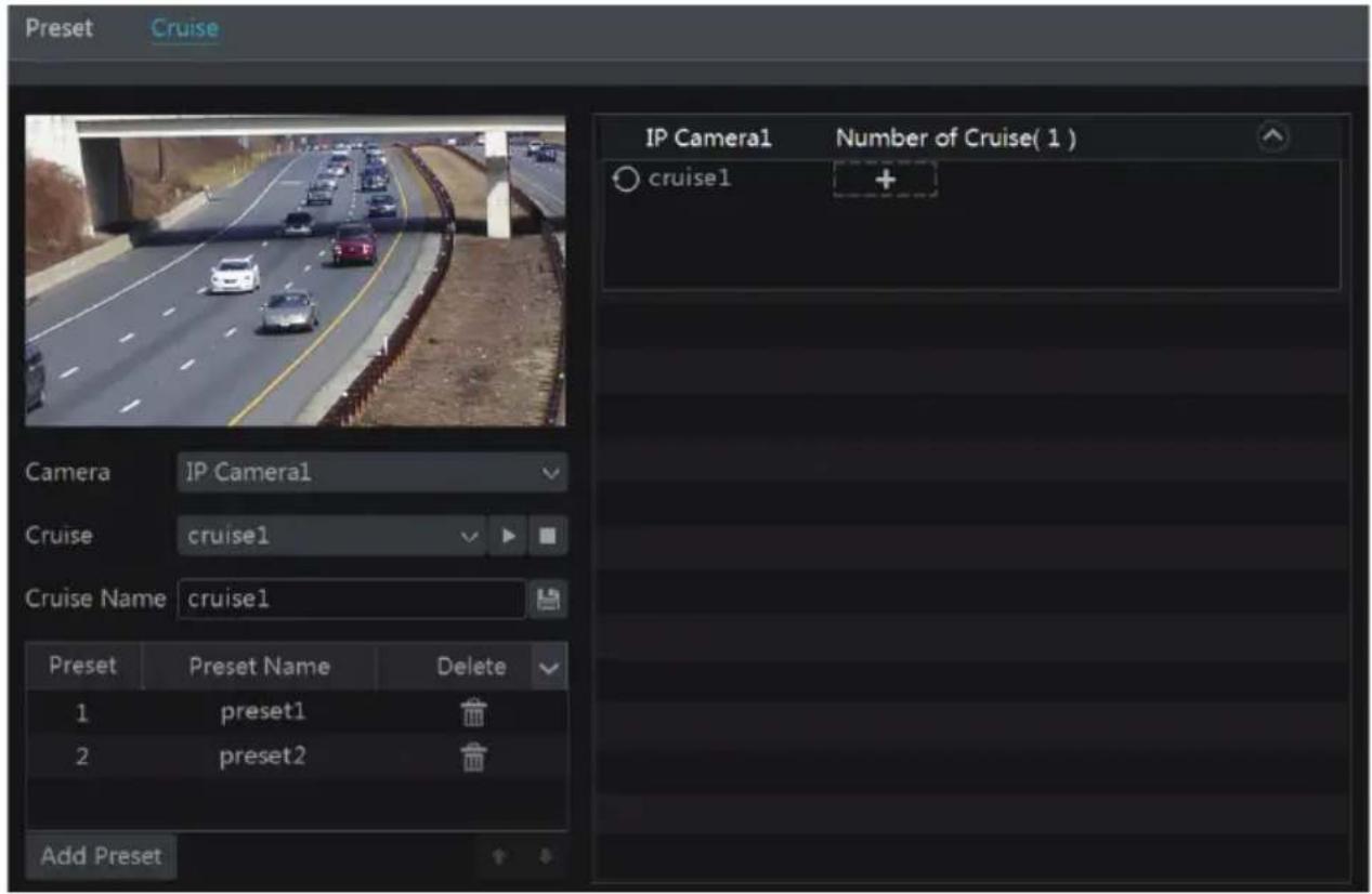
Add Cruise
Click in the camera list on the right side of the interface to display the cruise information of the dome and then click + to add cruise. The operations of the “Add Cruise” window are similar to that of the PTZ control interface; please see 6.1 PTZ Control Interface Introduction for details.
Edit Cruise
Select the camera and cruise in the “Cruise” interface. Input the new cruise name and then click to save the cruise name. Click “Add Preset” to add preset to the cruise. Click to delete the preset from the cruise. Click one preset in the preset list and then click to move down the preset and click to move up the preset. Click to start the cruise and click to stop it.
Delete Cruise
Click in the camera list on the right side of the interface to display the cruise information of the dome and then click on the top right corner of the cruise to delete the cruise.
7 Record & Disk Management
7.1 Record Configuration
7.1.1 Mode Configuration
Please format the HDDs before recording (refer to 7.5 Disk Management for details). Click Start→Settings→Record→Mode Settings to go to the mode settings interface. You can set the record time under the “Manual Record Settings” and then click “Apply” button to save the
settings. There are two record modes: auto mode and manual mode.

Auto Mode
Motion Record: System will record on Motion activity only.
Sensor Record: System will record on Alarm Sensor trigger only.
Motion Record+Sensor Record: System will record on either Motion activity or Alarm Sensor trigger or both.
Always(24 x 7) Record+Motion Record: System records all the time and on Motion activity
Always(24 x 7) Record+Sensor Record: System records all the time and on Alarm Sensor trigger
Always(24 x7) Record+Motion Record+Sensor Record: System records all the time and on Motion activity and/or Alarm Sensor trigger.
Select one Auto mode to pop up the corresponding window. Set the video encode, resolution, FPS, bitrate and audio of each camera and then click "OK" to save the settings.
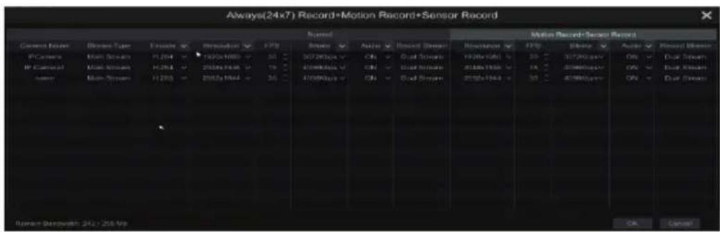
Video Encode: the available options will be H.265 and H.264 if the connected IP camera
supports H.265, or the option will be H.264 only.
Resolution: the higher the resolution is, the clearer the image is.
FPS: the higher the frame rate is, the more fluid the video is. However, more storage room will be taken up.
Bitrate: the higher the image quality you choose, the more bit rate will be required.
▶ Manual Mode
If the manual mode is selected, you need to set the encode parameters and record schedules of each camera. See 7.2 Encode Parameters Setting and 7.3 Schedule Setting for details.
7.1.2 Advanced Configuration
Click Start→Settings→Record→Advanced to go to the following interface. Enable or disable cycle record (cycle record: the earliest recorded data will be replaced by the latest when the disks are full). Set the pre-alarm record time, post-alarm record time and expiration time of each camera and then click “Apply” to save the settings.
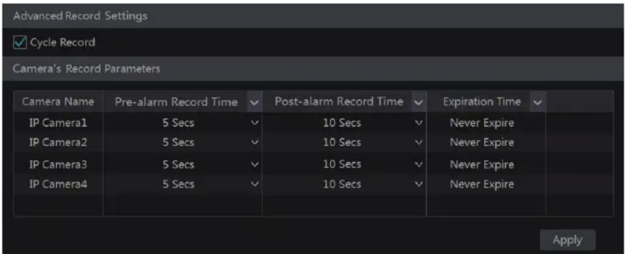
Pre-alarm Record Time: set the time to record before the actual recording begins.
Post-alarm Record Time: set the time to record after the actual recording is finished.
Expiration Time: set the expiration time for recorded video. If the set date is overdue, the recorded data will be deleted automatically.
7.2 Encode Parameters Setting
Click Start→Settings→Record→Encode Parameters to go to the interface as shown below. Set the video encode, resolution, FPS, bitrate and audio of main stream for each camera in “Event Record Stream” and “Timing Record Stream” interfaces. Click “Apply” to save the settings. You can set the record stream of each camera one by one or batch set them for all cameras.
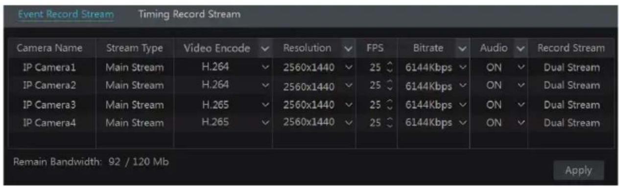
Click Start→Settings→Record→Stream Settings to go to “Sub-stream” interface. Set the video encode, resolution, FPS and bitrate of sub-stream for each camera in the interface and then click “Apply” to save the settings.

7.3 Schedule Setting
7.3.1 Add Schedule
Click Start→Settings→Record→Record Schedule→Edit Schedules to go to the interface as shown below. “24 x 7”, “24 x 5” and “24 x 2” are the default schedules; you cannot edit or delete “24 x 7” while “24 x 5” and “24 x 2” can be edited and deleted. Click the schedule name to display the detailed schedule information on the left side of the interface. The seven rows stand for the seven days in a week and each row stands for 24 hours in a day. Blue stands for the selected time and gray stands for unselected time.
Click + to add a new schedule. Refer to the picture below.
bar
| Day | Copy To | Manual | All | Reverse | Clear All | |-------|---------|--------|-----|---------|-----------| | Sun | 0 | 2 | 4 | 6 | 8 | | Mon | 0 | 2 | 4 | 6 | 8 | | Tues | 0 | 2 | 4 | 6 | 8 | | Wed | 0 | 2 | 4 | 6 | 8 | | Thur | 0 | 2 | 4 | 6 | 8 | | Fri | 0 | 2 | 4 | 6 | 8 | | Sat | 0 | 2 | 4 | 6 | 8 |Set the schedule name and schedule time and then click "Add" to save the schedule. You can
set day schedule or week schedule. 📋: add button; 📋: delete button.
➢ Set Day Schedule
Click and then drag the cursor on the time scale to set record time; click and then drag the cursor on the time scale to delete the selected area.
You can manually set the record start time and end time. Click 📄 or 🌐 and then click “Manual” on each day to pop up a window as shown below. Set the start and end time in the window and then click “OK” to save the settings.
Click "All" to set all day recording; click "Reverse" to swap the selected and unselected time in a day; click "Clear All" to clear all the selected area in a day.
Click "Copy To" to copy the schedule of the day to other days. Refer to the picture below. Check the days in the window and then click "OK" to save the settings.

➢ Set Week Schedule
Click 📄 or 📋 and then click “Manual” beside 📋 to set the week schedule. Refer to the picture below. Set the start and end time, check the days in the window and then click “OK” to save the settings.
Click “All” to set all week recording; click “Reverse” to swap the selected and unselected time in a week; click “Clear All” to clear all the selected area in a week.
7.3.2 Record Schedule Configuration
Click Start→Settings→Record→Record Schedule→Schedule Configuration to go to the interface as shown below. Set the schedule of sensor record, motion record and timed record. Click “None” in the drop-down menu to clear the schedule. Click “Apply” to save the settings.
| Camera Name | Sensor Record Schedule | Motion Record Schedule | Timed Record Schedule |
| IP Camera1 | 24×7 | 24×7 | 24×7 |
| IP Camera2 | 24×7 | 24×7 | 24×7 |
| IP Camera3 | 24×5 | 24×5 | 24×5 |
| IP Camera4 | 24×5 | 24×5 | 24×5 |
| Apply | |||
Go to “Edit Schedules” interface and then click 📄 to edit the schedule. The settings of “Edit Schedule” are similar to that of the “Add Schedule”. Click 📄 to delete the schedule.
7.4 Record Mode
7.4.1 Manual Recording
Method One: Click 📄 on the tool bar at the bottom of the live preview interface to enable recording of the camera.
Method Two: Go to live preview interface and then right-click and select "Manually Record On" in the camera window or click on the tool bar under the camera window to start recording.
Note: Click Start→Settings→Record→Mode Settings and then set the manual record time in the interface. Click "Apply" to save the settings.
7.4.2 Timing Recording
Timing Recording: the system will record automatically according to the schedule.
Set the timing record schedule of each camera. See 7.3 Schedule Setting for details.
7.4.3 Motion Based Recording
Motion Based Recording: the system will start motion based recording when motion activity appears during the scheduled times. The setup steps are as follows:
☐ Set the motion based recording schedule of each camera. See 7.3 Schedule Setting for details.
☐ Enable motion and set the motion area of each camera. See 9.2.1 Motion Configuration for details.
The camera will start motion based recording once you finish the above settings.
7.4.4 Sensor Based Recording
☐ Set the sensor based recording schedule of each camera. See 7.3 Schedule Setting for details.
☐ Set the NO/NC type of the sensor, enable the sensor alarm and then check and configure the "Record". See 9.1 Sensor Alarm for details.
7.5 Disk Management
Click Start→Settings→Disk→Disk Management to go to disk management interface. You can view the NVR's disk number and disk status in the interface. Click "Formatting" button to format the HDD.
![Disk Capacity[GB] Disk Serial No. Disk Model Status Operation Disk2 931 XXX XXX ✓ RW Formatting](/content/2026/06/1213934/images/4e3228b5eae79e3bbd7dee989493d2fbf5be2309c9cf9a9eb4100d0862d676c4.jpg)
Note: New HDD's need to be formatted for normal use.
7.5.1 Storage Mode Configuration
Click Start→Settings→Disk→Storage Mode to go to the interface as shown below.
| Storage Mode Group | ||||||
| Group | Disk (Capacity: 931GB) | Disk2 + | ||||
| 1 | Disk(1) Camera(4) | |||||
| Camera | IP Camera1 | IP Camera2 | IP Camera3 | IP Camera4 | ||
| 2 | Disk(0) Camera(0) | |||||
| 3 | Disk(0) Camera(0) | |||||
| 4 | Disk(0) Camera(0) | |||||
There are four disk groups. By using disk group, you can correspond the camera to disk (the recorded data of the camera in the group will be stored onto the disks in the same group).
The added disks and cameras will be added into group one automatically. The disks and cameras in the groups can be deleted except group one (select a disk group and then click on the top right corner of the added disk or camera to delete it from the group). The deleted disks and cameras will be moved into group one automatically.
Each group can add the disks and cameras from other groups. Each disk and camera can only be added into one group. Select a disk group and then click + in the disk or camera row to pop up a window. Check the disks or cameras in the window and then click "Add".
7.5.2 View Disk and S.M.A.R.T. Information
Click Start→Settings→Disk→View Disk Information to view the HDD information; click “S.M.A.R.T. Information” to view the working status of the HDD. Refer to the picture below.
8 Playback & Backup
8.1 Instant Playback
Click ▶ on the tool bar at the bottom of the preview camera window to play back the record (click ↑ on the tool bar at the bottom of the live preview interface to set the default playback time). Refer to the picture below. Drag the playback progress bar to change the playback time. You can also use the right-click menu “Instant Playback” in the camera window and then set the instant playback time to play back the recording.

natural_image
Highway traffic scene with multiple cars and a tree-lined lane, captured in a video player interface (no readable text or symbols on vehicles)8.2 Playback Interface Introduction
Click 🖼️ on the tool bar at the bottom of the live preview interface or click Start→Playback to go to the playback interface as shown below (click 🔗 on the tool bar at the bottom of the live preview interface to set the default playback time).
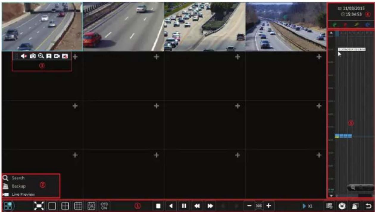
The added cameras will playback in the playback interface automatically. You can also add the camera manually. Click + in the playback window to pop up the “Add Camera” window. Check the cameras in the window and then click “Add” to add camera. The system supports a maximum of 16 synchronous cameras.
The buttons on the tool bar (area ①) at the bottom of the playback interface are introduced in the table below.
| Button Meaning |
| Button Meaning | |
 | Start button. Click it to pop up area 2. |
 | Full screen button. Click it to show full screen; click it again to exit the full screen. |
 | Screen mode button. |
 | OSD ON button. Click it to enable OSD; click to disable OSD. |
| [AHHG] | Stop button. |
| [D0ZY] | Rewind button. Click it to play video backward. |
 | Play button. Click it to play video forward. |
| [YZZ3] | Pause button. |
| [ZHAO] | Click to decrease the playing speed. |
| [WAY] | Click to increase the playing speed. |
| [HZY2] | Previous frame button. It works only when the forward play is paused in single screen mode. |
 | Next frame button. It works only when the forward play is paused in single screen mode. |
| [BWZ3] | Click  to go back 30s and click [OX62] to go forward 30s. to go back 30s and click [OX62] to go forward 30s. |
| [SOSO] | Event list/tag button. Click it to view the event recording of manual/schedule/sensor/ motion and tag information. |
| [4857] | Backup button. Drag the mouse on the time scale to select the time periods and cameras, and then click the button to back up the record. |
 | Backup status button. Click it to view the backup status. |
 | Back button. Click it to return. |
Introduction of area □ :
| Button Meaning | |
 | Click to go to record search interface; see 8.3 Record Search & Playback for details. |
 | Click to go to backup interface; see 8.4 Backup for details. |
 | Click to go to live preview interface; see Chapter 5 Live Preview Introduction for details. |
Click on the playback window to show the tool bar as shown in area ③; right click on the window to show the menu list. The tool bar and menu list are introduced in the table below.
| Button | Menu List | Meaning | |
 | -- | Move tool. Click and hold to move the tool bar anywhere. | |
 | Enable Audio | Click to enable audio. You can listen to the camera audio by enabling audio. | |
 | Snap | Click to take a snapshot. | |
 | Zoom In | Click to go to the zoom in interface. The zoom in interface is similar to that of the camera window in the live preview interface. |
 | Add Tag | Click to add tag. You can play back the recording by searching the added tag. Click and then input the tag name in the popup window. Click “Add” to add tag. |
 | Switch Camera | Click to switch the playback camera. Click and then check the camera in the popup window. Click “OK” to change the camera. |
 | Close Camera | Click to close the playback camera. |
Introduction of area ④:
Click 📋 to set the date; click 🔒 to set the time and then the playback will play the recording from the time you set. You can check the record type as required for record playback; first you should click 📄 on the tool bar at the bottom of the interface to clear all the playback cameras, then check the record type ( 🎨: manual record; 🎩: sensor based record; 🎪: motion based record; 🎫: schedule recording) and finally click + in the playback window to add camera for playback (the recording time scale will show the record data of the checked record type only after the above operations).
Introduction of the record time scale (area ⑤):
A tool bar will appear after moving the mouse to the record time scale. Click / to zoom in/out of timeline; click to recover the timeline to 24 hours' ratio. Drag the timeline or slide the scroll wheel of the mouse on the time scale to show hidden time on the top or bottom of the timeline. You can also click to show the hidden time on the top of the timeline or click to show the hidden time on the bottom of the timeline. Drag the slider at the bottom of the time scale to show hidden playback cameras.
The record time scale shows different record types with different colors. The green block stands for manual record, red block stands for sensor based record, yellow block stands for motion based record and blue block stands for schedule record. Click the record block to set the time and then the camera will play the recording from the time you set.
Drag the color block on the time scale to select the backup area and then right click the area or click 📋 to pop up a backup information window. Click “Backup” button in the window to pop up the backup window. Select the device, backup path and backup format and then click “Backup” button to start the backup.
8.3 Record Search & Playback
8.3.1 Search & Playback by Time-sliced Image
☐ Click Start→Search→By Time-sliced Image to go to “By Time-sliced Image” tab. There are two view modes: by time and by camera. In the time view mode, a maximum of 64 camera thumbnails can be showed. If the camera thumbnail number is more than 64, the cameras will be listed directly by their camera name, not the thumbnail. A maximum of 196 camera names can be listed. If the camera name number is more than 196, the time view mode will be disabled and the camera view mode will be available only.

☐ Select one camera in the interface and then click "Open" button.
☐ Click the image box to play the record in the small playback box on the left side of the interface (the box which has image inside indicates that the record data exist).
☐ Refer to the picture below. Drag the color blocks on the time scale to select the record data and then click “Backup” button to pop up a window; select the device, backup path and backup format in the window and then click “Backup” button to start the backup.
☐ Click “Playback” button to play the recording in the playback interface (refer to 8.2 Playback Interface Introduction for details). Click “Close” to close the interface.
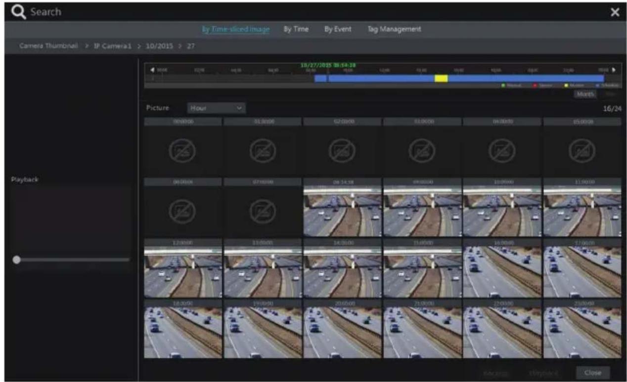
Time Slice Mode Selecting:
Method One: Click “Year”, “Month” or “Day” button under the record time scale to select the time slice mode. In “Day” mode, click / ▶ on the left/right side of the time scale to view the recording of the last/next day; click “Minute” in the “Picture” option under the time scale to select “Minute” mode (in “Minute” mode, click the time scale to change the time of the 60 display windows) and click “Hour” to select “Hour” mode.
Method Two: Click ➤ beside “Camera Thumbnail” on the left top corner of the interface to select the time slice mode.
Method Three: Right-click the mouse on any area of the time-sliced interface to go back to the upper interface.
8.3.2 Search & Playback by Time
☐ Click Start→Search→By Time to go to “By Time” tab as shown below.
☐ Click 📋 on the bottom of the interface to add playback camera. A maximum of 16 cameras can be added for playback. Click “Modify” on the top right corner of the camera window to change the camera and click “Clear” to remove the camera.
☐ Click the camera window to play the record in the small playback box on the left side of the interface. You can set the date on the top left of the interface, check the event type as required and click the time scale or click under the time scale to set the time. The camera window will play the recording according to the time and event type you set.
☐ Drag the color blocks on the time scale to select the record data and then click “Backup” button for record backup. Click “Playback” button to play the recording in the playback interface.

8.3.3 Search & Playback by Event
☐ Click Start→Search→By Event to go to “By Event” tab as shown below.

☐ Check the event type in the interface as required.
☐ Click ☑ to set the start time and end time on the top left of the interface.
☐ Check cameras on the left side of the interface and then click 🔒 Search to search the recording. The searched recording will be displayed in the list.
☐ Click ▶ in the list to play back the recording in the popup window. Select one record
data in the list and then click “Backup” button for record backup.
☐ Select one record data in the list and then click “Playback” button to play the recording in the playback interface.
8.3.4 Search & Playback by Tag
Only if you add the tags can you play the recording by tag search. Click Start→Playback to go to the playback interface and then click ★ on the bottom of the camera window to add tag when you want to mark the playback time point of the selected camera.
Click Start→Search→Tag Management to go to “Tag Management” tab.
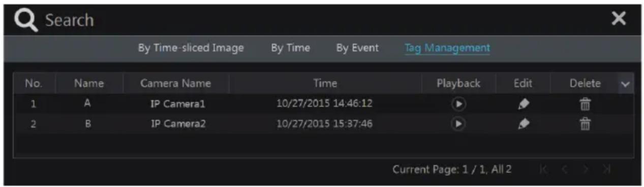
Click 🖼️ in the interface to play the recording. Click to delete the tag.

8.4 Backup
The record data and the snapped pictures can be backed up through network, USB (U disk or USB mobile HDD) or e-SATA (only available for some models). The file system of the backup devices should be FAT32 format.
8.4.1 Backup by Time
☐ Click Start→Backup→By Time to go to the “By Time” tab.
☐ Click 📋 in the tab to pop up the add camera window. Check the cameras in the window and then click “Add” button. Click “Modify” on the top right corner of the camera window to change the camera and click “Clear” to remove the camera.
☐ Set the date on the top left of the interface. Drag the time scale to set the backup time period or click 📋 under the time scale to set the backup start time and end time.

☐ Click “Backup” button to pop up the “Record Backup” window as shown below. Select the device name, backup format and path and then click “Backup” button to start the backup.
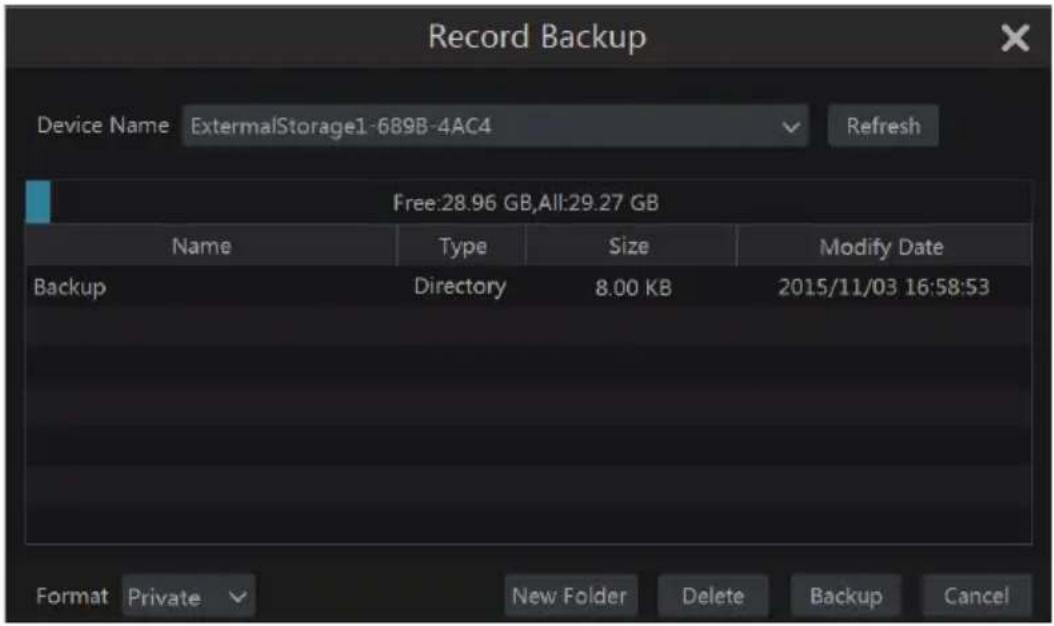
Note: If you back up the recording in private format, the system will back up a RPAS player to USB device automatically. The private format recording can be played by RPAS player only.
8.4.2 Backup by Event
☐ Click Start→Backup→By Event to go to “By Event” tab.

☐ Click ☐ to set the start time and end time on the left top of the interface.
☐ Check the event types and cameras.
☐ Click 🔒 Search to search the record. The searched record data will be displayed in the list.
Click in the list to play the recording in a small popup playback window. Click to backup the recording. Check one recorded data or above in the list and then click "Backup" button to back up the recorded data.
8.4.3 Image Management
Click Start→Backup→Image Management to go to “Image Management” tab. The system will display all the snapshot images automatically in the list.

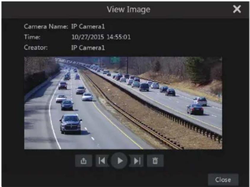
Click to delete the image. Click to pop up the "Export" window. Select the device name and save path in the window and then click "Save" button. Click to pop up the "View Image" window. Click to export the image. Click to view the previous image; click to view the next image; click to delete the image; click to play all the images.
8.4.4 View Backup Status
Click Start→Backup→Backup Status or click 📄 on the tool bar at the bottom of the playback interface to view the backup status.
9 Alarm Management
9.1 Sensor Alarm
To complete the entire sensor alarm settings, you should enable the sensor alarm of each camera and then set up the alarm handling of each camera.
☐ Click Start→Settings→Alarm→Sensor Alarm to go to the following interface.

☐ Select the alarm type (NO or NC) according to trigger type of the sensor.
Enable the sensor alarm of each camera.
☐ Check the “Record”, “Snap”, “Alarm-out” and “Preset” and enable or disable the “Buzzer”, “Pop-up Video”, “Pop-up Message Box” and “E-mail” as required.
☐ Click "Apply" to save the settings.
The configuration steps of the above mentioned alarm linkages are as follows.
Record: check it and then the "Trigger Record" window will pop up automatically (you can also click "Configure" button to pop up the window). Select camera on the left side and then
click >> to set the camera as the trigger camera. Select trigger camera on the right side and then click << to cancel the trigger camera. Click “OK” button to save the settings. The trigger cameras will record automatically when the sensor alarm is triggered.
Snap: check it and then the “Trigger Snapshot” window will pop up automatically. Configure the trigger camera in the window. The trigger cameras will snap automatically when the sensor alarm is triggered.
Alarm-out: check it and then the “Trigger Alarm-out” window will pop up automatically. Configure the trigger alarm-out in the window. The system will trigger the alarm-out automatically when the sensor alarm is triggered. You need to set the delay time and the schedule of the alarm outputs. See 9.4.1 Alarm-out for details.
Preset: check it and then the “Trigger Preset” window will pop up automatically. Configure the trigger preset of each camera. To add presets, please see 6.2 Preset Setting for details.
Buzzer: if enabled, the system will begin to buzz when the sensor alarm is triggered. To set the delay time of the buzzer, please see 9.4.4 Buzzer for details.
Pop-up Video: After camera setting, the system will pop up the corresponding video automatically when the sensor alarm is triggered. To set the duration time of the video, please see 9.4.3 Display for details.
Pop-up Message Box: if enabled, the system will pop up the corresponding alarm message box automatically when the sensor alarm is triggered. To set the duration time of the message box, please see 9.4.3 Display for details.
E-mail: if enabled, the system will send an e-mail when the sensor alarm is triggered. Before you enable the email, please configure the recipient's e-mail address first (see 11.1.4 E-mail Configuration for details).
9.2 Motion Alarm
Motion Alarm: when the motion object appears in the specified area, it will trigger the alarm. You should enable the motion of each camera first and then set the alarm handling of the camera to complete the whole configuration of the motion alarm.
9.2.1 Motion Configuration
☐ Click Start→Settings→Camera→Motion to go to the following interface.
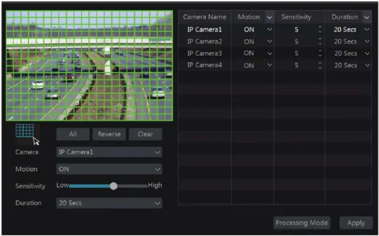
☐ Select the camera, enable the motion and set the sensitivity and duration of the camera.
Sensitivity: the higher the value is, the more sensitive it is to motion. You should adjust the value according to the practical conditions since the sensitivity is influenced by color and time (day or night).
Duration: it refers to the interval time between the adjacent motion detections. For instance, if the duration time is set to 10 seconds, once the system detects motion, it will go into alarm and would not detect any other motion (specific to camera) for 10 seconds. If there is another motion detected during this period, it will be considered as continuous movement; otherwise it will be considered as a single motion.
☐ Drag the camera image to set the motion area. You can set more than one motion area. Click “All” to set the whole camera image as the motion area. Click “Reverse” to swap the motion area and the non-motion area. Click “Clear” to clear all the motion areas.
☐ Click “Apply” to save the settings. Click “Processing Mode” to go to the alarm handling configuration interface of the motion alarm.
9.2.2 Motion Alarm Handling Configuration
☐ Click Start→Settings→Alarm→Motion Alarm to go to the following interface.
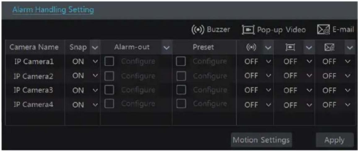
Enable or disable "Snap", "Alarm-out", "Preset", "Buzzer", "Pop-up Video" and "E-mail". The alarm handling setting of motion alarm is similar to that of the sensor alarm (see 9.1 Sensor Alarm for details).
☐ Click “Apply” to save the settings. You can click “Motion Settings” to go to the motion configuration interface.
9.3 Exception Alarm
9.3.1 Exception Handling Settings
☐ Click Start→Settings→Alarm→Exception→Exception Handling Settings to go to the interface as shown below.
☐ Enable or disable “Alarm-out”, “Buzzer”, “Pop-up Message Box” and “E-mail”. The exception handling settings are similar to that of the sensor alarm (see 9.1 Sensor Alarm for details).
☐ Click “Apply” to save the settings.
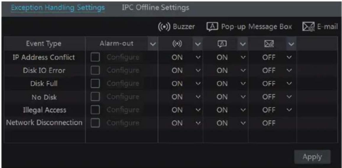
9.3.2 IPC Offline Settings
☐ Click Start→Settings→Alarm→Exception→IPC Offline Settings to go to the interface as shown below.

☐ Enable or disable “Snap”, “Alarm-out”, “Preset”, “Buzzer”, “Pop-up Video”, “Pop-up Message Box” and “E-mail”. The IPC Offline Settings are similar to that of the sensor alarm (see 9.1 Sensor Alarm for details).
☐ Click “Apply” to save the settings.
9.4 Alarm Event Notification
9.4.1 Alarm-out
☐ Click Start→Settings→Alarm→Event Notification to go to the following interface.
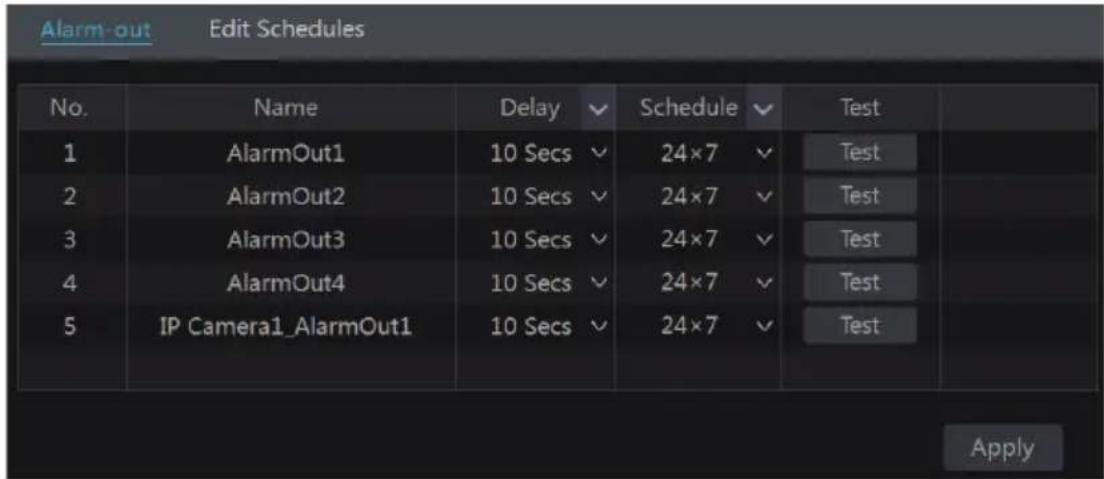
Set the delay time and the schedule of each alarm-out. You can click "Edit Schedules" to edit the schedules (see 7.3.1 Add Schedule for details).
☐ Click "Apply" to save the settings. You can click "Test" to test the alarm output.
9.4.2 E-mail
Click Start→Settings→Alarm→Event Notification→E-mail to go to the e-mail configuration interface. Set the e-mail address of the recipients. See 11.1.4 E-mail Configuration for details.
9.4.3 Display
Click Start→Settings→Alarm→Event Notification→Display to go to the display configuration interface. Set the duration time of the pop-up video and the pop-up message box. Click “Apply”
to save the settings.
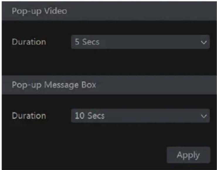
9.4.4 Buzzer
Click Start→Settings→Alarm→Event Notification→Buzzer to go to the buzzer configuration interface. Set the delay time of the buzzer and then click “Apply” to save the setting. You can click “Test” to test the buzzer.

9.5 Manual Alarm
Click 📁 on the tool bar at the bottom of the live interface to pop up a window. Click “Trigger” to start alarm. Click “Clear” to stop alarm.
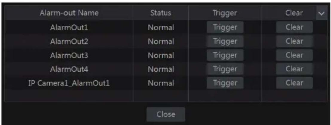
9.6 View Alarm Status
Click Start→Settings→Alarm→Alarm Status or click 📄 on the tool bar at the bottom of the live preview interface to view the alarm status.
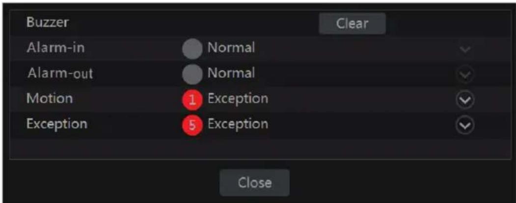
Click “Clear” button to stop the buzzer when the buzzer alarm happens. Click ▼ to view the detail information as shown below.

If the exception information is more than one page, you can input the number in the box and then click ➤ to jump to the specified page. Click ◀ / ➤ to view the exception alarm information in the previous/next page. Click ➤ to play the alarm record.
10 Account & Permission Management
10.1 Account Management
Click Start→Settings→Account and Authority→Account→Edit User to go to the interface as
shown below.
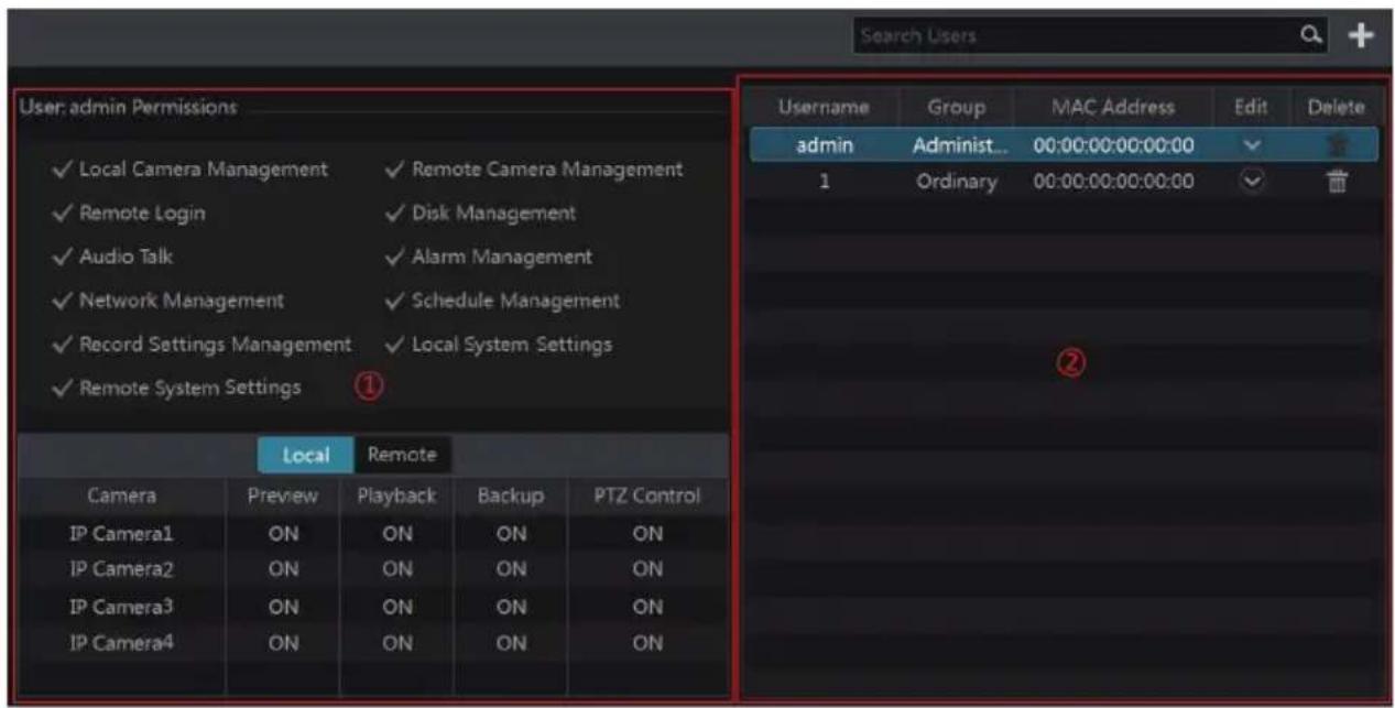
Area ① displays the user permissions. Area ② displays the user list. Click the user in the list to display its user permissions in area ①.
There are three default permission groups (“Administrator”, “Advanced” and “Ordinary”) available when adding accounts. You can manually add new permission group (see 10.3.1 Add Permission Group for details).
The user admin owns all the permissions and it can manage the system's accounts. Group "Administrator" owns all the permissions displayed in area ① and its permissions cannot be changed while the permissions of "Advanced" and "Ordinary" can be changed.
10.1.1 Add User
☐ Click Start→Settings→Account and Authority→Account→Add User or click beside the search box to pop up the window as shown below.

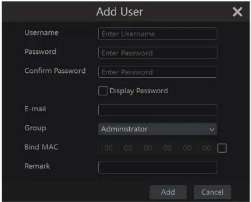
Set the username, password and group. The e-mail address, MAC address and the remark are optional (input the MAC address after you check it). Click “Add” to add the user.
10.1.2 Edit User
Click Start→Settings→Account and Authority→Account→Edit User and then click in the user list or double click the user to edit the user information. Click to delete the user (the user admin cannot be deleted).
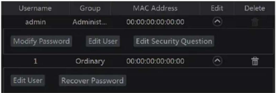
➢ Edit Security Question
You can set password security only for admin. Click “Edit Security Question” and then set questions and answers in the popup window. If you forget the password, please refer to Q4 in Appendix A FAQ for details.
Modify Password
Only the password of admin can be modified. Click “Modify Password” to pop up a window. Input the current password and then set new password. Click “OK” to save the settings.
▶ Recover Password
Click "Recover Password" to reset the password to 123456.
Edit User
Click “Edit User” to pop up the window as shown below. The admin is enabled, its permission control is closed and permission group cannot be changed by default. You can enable or disable other users (if disabled, the user will be invalid), open or close their permission control (if closed, the user will get all the permissions which the administrator permission group has) and set their permission groups. Click “OK” to save the settings.

10.2 User Login & Logout
Login: Click Start→Login or directly click the preview interface and then select username and enter the password in the popup window. Click “Login” button to log in the system.
Logout: Click Start→Logout or click Start→Shutdown to pop up the “Shutdown” window. Select “Logout” in the window and then click “OK” button to log out the system.
10.3 Permission Management
10.3.1 Add Permission Group
Click Start→Settings→Account and Authority→Account→Edit Permission Group to go to the interface as shown below.
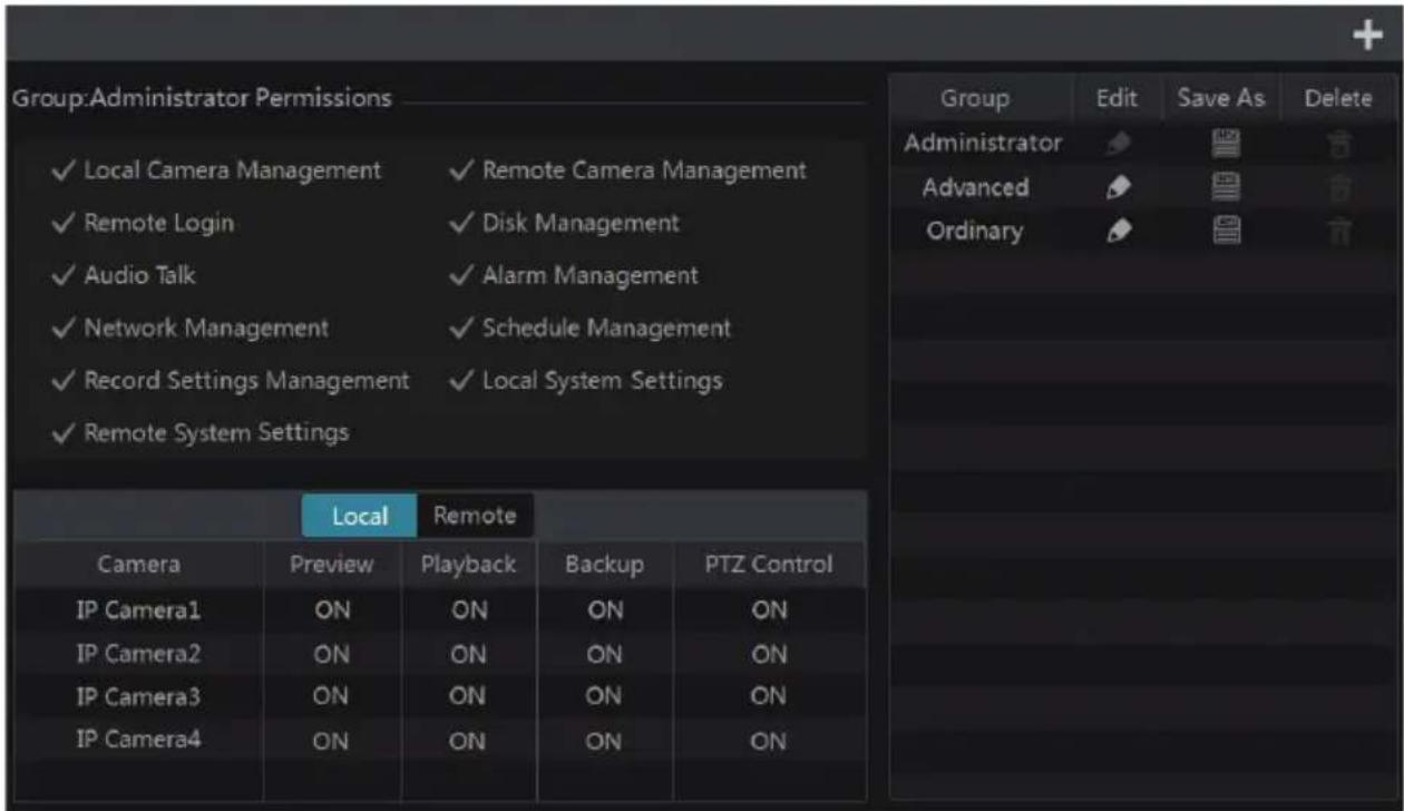
Click + to add permission group. Set the group name, check the permissions as required and then set the “Local” and “Remote” permissions. Click “Add” to save the settings.
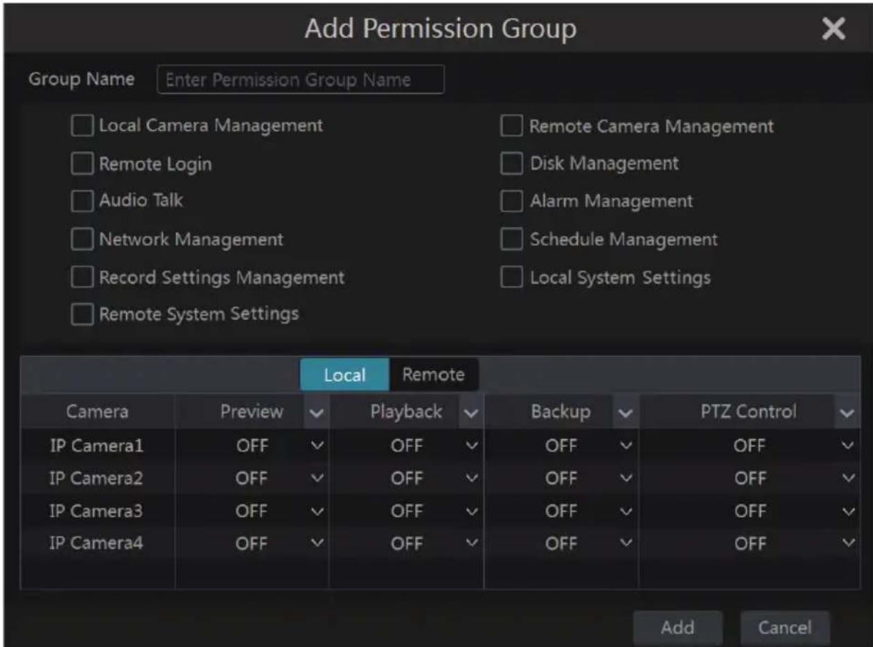
10.3.2 Edit Permission Group
Go to “Edit Permission Group” interface and then click 📋 in the group list to edit the permission group (the operations of the “Edit Permission Group” are similar to that of the “Add Permission Group”, please see 10.3.1 Add Permission Group for details). Click 📋 to save the group as another group. Click 📋 to delete the permission group. The three default permission groups (“Administrator”, “Advanced” and “Ordinary”) cannot be deleted.
10.4 Black and White List
☐ Click Start→Settings→Account and Authority→Security to go to the following interface.
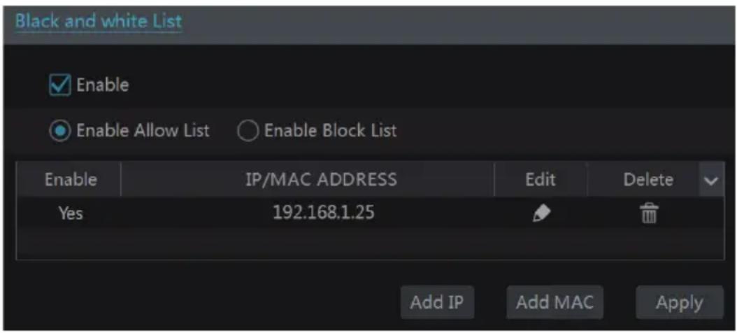
☐ Check “Enable” and then choose “Enable Allow List” or “Enable Block List” (the PC client of which the IP address is in the allow list can access NVR remotely while the PC client in the block list cannot).
☐ Add IP/IP segment/MAC. Click “Add IP” or “Add MAC” button and then check “Enable” in the popup window (only if you check it can the IP/IP segment/MAC you add be effective).
Enter the IP/IP segment/MAC and then click "OK" button. In the above interface, click to edit IP/IP segment/MAC, click 📄 to delete it. Click "Apply" to save the settings.

11 Device Management
11.1 Network Configuration
11.1.1 TCP/IPv4 Configuration
IP Address Settings
Click Start→Settings→Network→TCP/IPv4 to go to the following interface. Check “Obtain an IP address automatically” and “Obtain DNS automatically” to get the IP address and DNS automatically, or manually input IP address, subnet mask, gateway, preferred DNS and alternate DNS. Click “Apply” to save the settings.
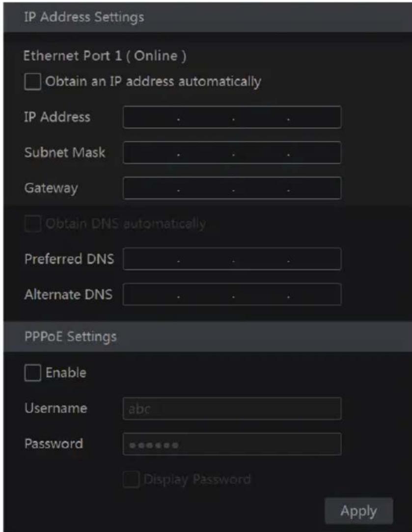
Internal Ethernet Port Introduction:
If you use the NVR with the PoE network ports, the online state of the internal Ethernet port will be shown on the interface. Refer to the picture below.
The internal Ethernet port is the port which connects all the PoE ports with the NVR system. The PoE ports are available if the internal Ethernet port is online; if it is offline, all the PoE ports will be unavailable. The IP address and subnet mask of the internal Ethernet port can be changed to make the port in the same network segment with the IP cameras which directly connect to the PoE ports of the NVR (it is not recommended to change the IP address and subnet mask of the internal Ethernet port).

▶ PPPoE Settings
In the above interface, check "Enable" in "PPPoE Settings" and then input the username and password obtained from the dealer. Click "Apply" to save the settings.
11.1.2 Port Configuration
Click Start→Settings→Network→Port to go to the interface as shown below. Input the HTTP port, server port and RTSP port of the NVR and then click “Apply” to save the ports.

HTTP Port: the default HTTP port of the NVR is 80. The port number can be changed to others like 81. The port is used for remote access. If you want to access the NVR through IE, you should input the IP address plus HTTP port in the IE address bar like http://192.168.11.61:81.
Server Port: the default server port of the NVR is 6036. The server port number can be
changed as required. The port is used with the network video management system.
RTSP Port: RTSP real-time stream protocol can be used to control the sending of real-time data by media player which supports the RTSP real-time stream protocol, The default RTSP port is 554 and it can be changed as required.
Note: The HTTP port and server port of the NVR should be mapped to the router before you access the NVR via WAN.
11.1.3 DDNS Configuration
The DDNS is used to control the dynamic IP address through domain name. You can access the NVR easily if the DDNS is enabled and configured.
Click Start→Settings→Network→DDNS to go to the interface as shown below.

Check “Enable” and then select the DDNS type. Input the server address, domain name, username and password according to the selected DDNS type. Click “Test” to test the effectiveness of the input information. Click “Apply” to save the settings.
You will have to input the server address and domain name if some DDNS types are selected. Go to the relative DNS website to register domain name and then input the registered domain information here). Take www.vitekivpddns.com for example.
Input www.vitekivpddns.com in the IE address bar to visit its DNS website.

☐ Click Registration button to go to the interface as shown below. Set the DDNS account information (username, password and so on) and then click Submit button to save the account.
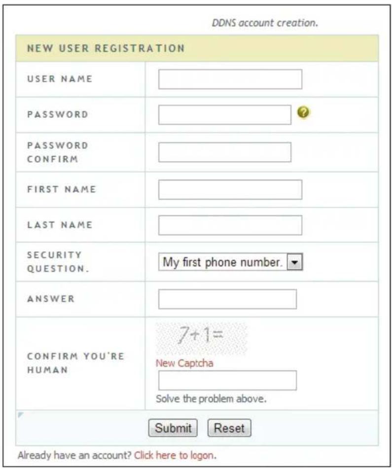
☐ Create domain name and then click Request Domain.
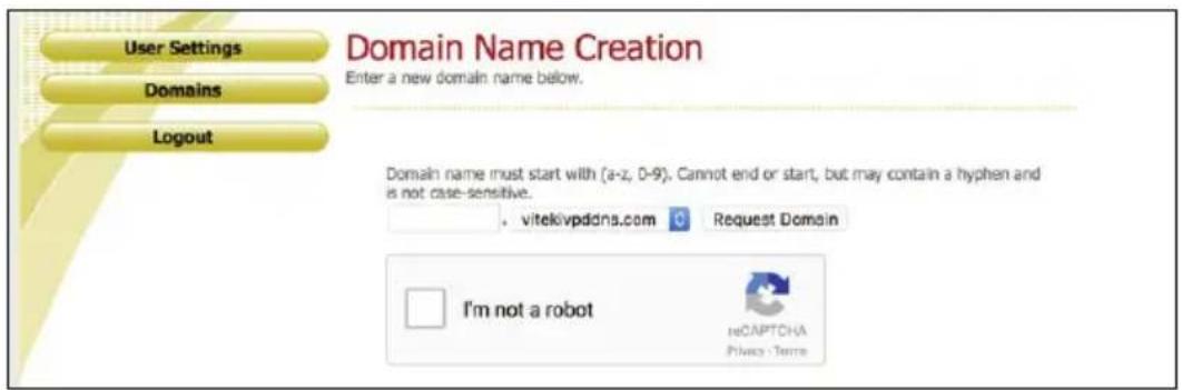
□ After you successfully request your domain name, you will see your domain name information in the list.

☐ Click Start→Settings→Network→DDNS to go to DDNS setting interface. Enable DDNS and then select the www.vitekivpddns.com DDNS type. Input the registered username, password and domain name and then click “Apply”.
☐ Map the IP address and HTTP port in the router (you can skip this step if UPnP function is enabled).
☐ Input the registered domain name plus HTTP port like http://xxx.vitekivpddns.com:81 in the IE address bar and then press Enter key to go to the IE client.
11.1.4 E-mail Configuration
Click Start→Settings→Network→E-mail to go to the following interface. Input the sender's e-mail address, name, password, SMTP server and SMTP port (you can click "Default" to reset the SMTP port to the default value) and then enable or disable the SSL and attaching image. Click "Test" to pop up a window. Input the e-mail address of the recipient in the window and then click "OK" button. The e-mail address of the sender will send an e-mail to the recipient. If the e-mail is sent successfully, it indicates that the e-mail address of the sender is configured correctly. Click "Apply" to save the settings.
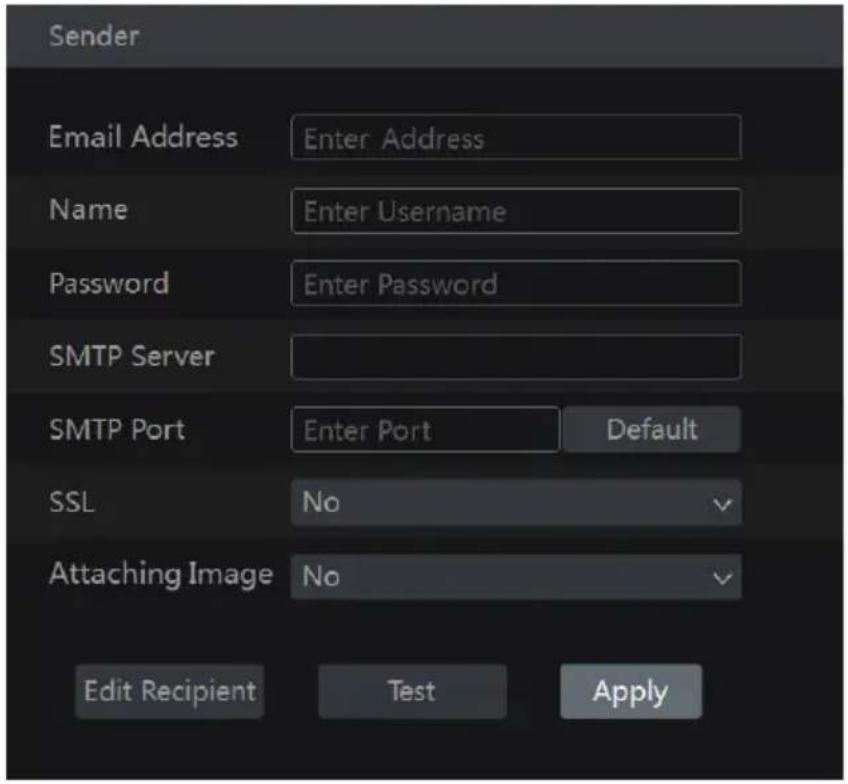
Click "Edit Recipient" to go to the following interface.

Click “Add” and then input the recipient’s e-mail address in the popup window. Click “Add” in the window to add the recipient. Click 📋 to delete the recipient in the list. Click “Apply” to save the settings. Click “Edit Sender” to go to the e-mail configuration interface of the sender.
11.1.5 UPnP Configuration
By UPnP you can access the NVR through IE client which is in WAN via router without port mapping.
☐ Click Start→Settings→Network→UPnP to go to the following interface.
☐ Make sure the router supports UPnP function and the UPnP is enabled in the router.
Set the NVR's IP address, subnet mask and gateway and so on corresponding to the router.
☐ Check “Enable” in the interface as shown below and then click “Apply” button.
Click “Refresh” button to refresh the UPnP status. If the UPnP status were still “Invalid UPnP” after refreshing it for many times, the port number would be wrong. Please change the mapping type to “Manual” and then click 📋 to modify the port until the UPnP status turns to “Valid UPnP”. Refer to the following picture. You can view the external IP address of the NVR. Input the external IP address plus port in the IE address bar to access the NVR such as http://183.17.254.19:81.

11.1.6 NAT Configuration
Click Start→Settings→Network→NAT to go to the interface for NAT configuration. Check “Enable” and then select the NAT server address (nat.autonat.com by default). Click “Apply” to save the settings.
11.1.7 View Network Status
Click Start→Settings→Network→Network Status to view the network status or click 📋 on the tool bar at the bottom of the live preview interface to view network status conveniently.
11.2 Basic Configuration
11.2.1 Common Configuration
Click Start→Settings→System→Basic→General Settings to go to the following interface. Set the device name, device No., language, video format and resolution. Enable or disable wizard, "Log In Automatically" and "Log Out Automatically" (if checked, you can set the wait time). Click "Apply" to save the settings.

Device Name: The name of the device. It may display on the client end or CMS that help user to recognize the device remotely.
Video Format: Two modes: PAL and NTSC. Select the video format according to the camera.
11.2.2 Date and Time Configuration
Click Start→Settings→System→Basic→Date and Time to go to the interface as shown below. Set the system time, date format, time format and time zone of the NVR. The default time zone is GMT+08 Beijing, Hong Kong, Shanghai, Taipei. If the selected time zone includes DST, the DST of the time zone will be checked by default. Click “Apply” to save the settings.
You can manually set the system time or synchronize system time with network through NTP.
Manual: select “Manual” in the “Synchronous” option and then click 📋 after the “System Time” option to set the system time.
NTP: select "NTP" in the "Synchronous" option and then input the NTP server.

11.3 Factory Default
Click Start→Settings→System→Maintenance→Factory Default and then click “Reset to factory default” button in the interface to reset to the factory default settings.
11.4 Device Software Upgrade
You can click Start→Settings→System→Information→Basic to view MCU, kernel version and firmware version etc. Before upgrade, please get the upgrade file from your dealer.
The upgrade steps are as follows:
☐ Copy the upgrade software into the USB storage device.
☐ Insert the USB storage device into the USB interface of the NVR.
☐ Click Start→Settings→System→Maintenance→Upgrade to go to “Upgrade” interface. Select the USB device in “Device Name” option and go to the path where the upgrade software exists. Select the upgrade software and then click “Upgrade”. The system may automatically restart during upgrading. Please wait for a while and do not power off the NVR during upgrading.
Note: The file system of the USB mobile device which is used for upgrading, backing up and restoring should be FAT32 format.
11.5 Backup and Restore
You can back up the configuration file of the NVR by exporting the file to other storage devices; you can load the configuration to other NVRs which are the same model by importing the configuration file.
Insert the USB storage device into the USB interface of the NVR and then click
Start→Settings→System→Maintenance→Backup and Restore to go to the interface.
- Backup
Select the USB device in "Device Name" option; go to the path where you want to store the configuration backup file and then click "Backup" button; finally click "OK" button in the popup window.
- Recover
Select the USB device in "Device Name" option; find the configuration backup file and then click "Recover" button; click "OK" button in the popup window.
11.6 View Log
Click Start→Settings→System→Maintenance→View Log to go to the log view interface. Select the log main type, click 🔒 to set start time and end time and then click “Search” button. The searched log files will be displayed in the list.

Choose the log file in the list and then click “Export” button to export the log file. Click on the “Content” title bar to pop up a menu list. Check contents in the menu list and then the log list will show the checked log contents only. Click to play the video log.
11.7 View System Information
Click Start→Settings→System→Information and then click the corresponding menu to view the “Basic”, “Camera Status”, “Alarm Status”, “Record Status”, “Network Status” and “Disk” information of the system.
11.8 Web LAN Access
☐ Click Start→Settings→Network→TCP/IPv4 to go to the “TCP/IPv4” interface. Set the IP address, subnet mask, gateway, preferred DNS and alternate DNS of the NVR.
☐ Open IE browser on a computer, input the IP address of the NVR in the IE address bar and then press enter to go to the login interface as shown below. You can change the display language on the top right corner of the login interface. Input the username and password of the NVR in the interface and then click “Login” to go to the live preview interface.

Notes: 1. Please make sure that the IP address of the NVR and the computer are both in the same local network segment. For example, supposing that the IP address of the computer is 192.168.1.41, the IP address of the NVR shall be set to 192.168.1.XXX. 2. If the HTTP port of the NVR is not 80, but other number instead, you need to input the IP address plus port number in the IE address bar when accessing the NVR over network. For example, the HTTP port is 81. You should enter http://192.168.1.42:81 in the IE address bar.
11.9 Web WAN Access
NAT Access
☐ Set the network of the NVR. Please refer to 11.1.1 TCP/IPv4 Configuration for details.
☐ Enable NAT and then set the NAT server address. Please refer to 11.1.6 NAT Configuration for details.
☐ Open IE browser on a computer, input the NAT server address http://www.autonat.com/n9000 in the IE address bar and then press enter to go to the interface as shown below (download and install the relative plugin according to the popup tip if you access the NVR through NAT for the first time).

Input the serial number (click 📋 on the tool bar at the bottom of the live preview interface to see the serial number of the NVR), user name (the user name of the NVR, admin by default) and password (the password of the NVR, 123456 by default) of the NVR, select the display language on the top right corner of the interface and then click “Login” button to go to the web client interface.
▶ PPPoE Access
☐ Click Start→Settings→Network→TCP/IPv4 to go to the “TCP/IPv4” interface. Check “Enable” in the “PPPoE settings” and then input the username and password you get from your ISP. Click “Apply” to save the settings.
☐ Click Start→Settings→Network→Network Status to view the IP address of the NVR.
☐ Open IE browser on a computer, input the IP address of the NVR like http://210.21.229.138 in the IE address bar and then press enter to go to the login interface. Input the username and password of the NVR in the interface and then click “Login” to go to the live preview interface.
Router Access
☐ Click Start→Settings→Network→TCP/IPv4 to go to the “TCP/IPv4” interface. Set the IP address, subnet mask, gateway, preferred DNS and alternate DNS of the NVR.
☐ Set the HTTP port (it is suggested to modify the HTTP port because the default HTTP port 80 might be taken up) and enable UPnP function in both the NVR and the router. If the UPnP function is not available in the router, you need to forward the LAN IP address, HTTP port and server port of the NVR to the router. Port mapping settings may be different in different routers, so please refer to the user manual of the router for details.
☐ Get the WAN IP address of the NVR from the router. Open IE browser on a computer, input the WAN IP address plus HTTP port like http://116.30.18.215:100 in the IE address bar and then press enter to go to the login interface. Input the username and password of the NVR in the interface and then click “Login” to go to the live preview interface.
Note: If the WAN IP address is a dynamic IP address, it is necessary for you to use the domain name to access the NVR. Click Start→Settings→Network→DDNS to set DDNS (see 11.1.3 DDNS Configuration for details). By using DDNS function you can use the domain name plus HTTP port like http://sunshine.dvrdydns.com:100 to access the NVR via internet.
11.10 Web Remote Control
The supported browsers of the remote surveillance are IE8/9/10/11, Firefox, Opera and Chrome (available only for the versions lower than 45) in Windows system and Safari in MAC system.
When you access the NVR through IE for the first time, you need to download and install the relative components for normal live view and playback. Please refer to the tips in the remote interfaces for details. The buttons and icons on the top right corner of the remote interface are introduced as follows.
admin: the current login username.
Logout: click it to log out and return to the login interface.
Modify Password: click it to change the password of the current login user. Input current password and then set a new password in the popup window. Click "OK" button to save the new password.
Local Settings: click it to change the local settings. Set the snapshot number and click "Browse" to set the snapshot path and record path as shown below. Click "Apply" button to save the settings.
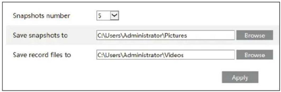
11.10.1 Remote Preview
Click “Live Display” in the remote interface to go to the preview interface. The preview interface consists of the four areas marked in the following picture.
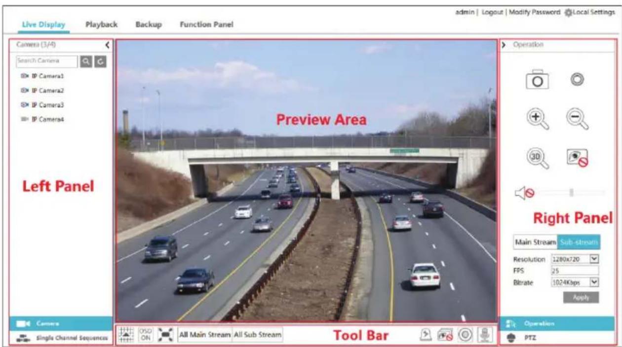
Start Preview
Select a window in the preview area and then click one online camera on the left panel to preview the camera in the window. You can click 📋 in the tool bar to preview all the cameras.
▶ Left Panel Introduction
Click < on the left panel to hide the panel and click > to show the panel. You can view all the added cameras and groups on the left panel.
• View Camera
Click 📄 Camera to view the cameras. You can view the number of all the added cameras and the online cameras. For instance, the left number 3 in Camera (3/4) on the left panel stands for the number of online cameras; the right number 4 stands for the number of all the added cameras. Input the camera name in the search box and then click 🔒 to search the camera. Click 🔒 to refresh the camera list.
• View Group
Click Single Channel Sequences to view the groups. The up side of the left panel displays all the groups and the down side displays all the cameras in the group.
Tool Bar Introduction
| Button Meaning | ||
| Screen mode button. | ||
| Click to disable OSD. Click to enable OSD. | ||
 | Click to show full screen. Right click on the full screen to exit full screen. | |
| All Main Stream | All Sub Stream | Click “All Main Stream” or “All Sub Stream” to set the stream of all the cameras. |
 | Manual alarm button. Click to pop up a window and then trigger and clear the alarm-out in the window manually. | |
 | Click to preview all the cameras. | |
 | Click to close all the preview cameras. | |
| [A3BA] | Click to start recording. Click [IMAGE] to stop recording. | |
| [3ZZY] | Click to enable talk with the NVR. | |
Right Panel Introduction
Click < on the right panel to show the panel and click > to hide the panel. Click PTZ at the bottom of the panel to go to "PTZ" panel. Click Operation to go to "Operation" panel.
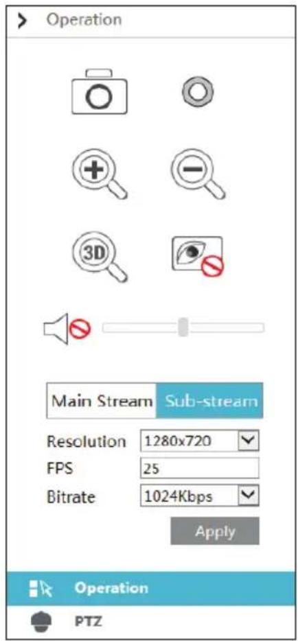
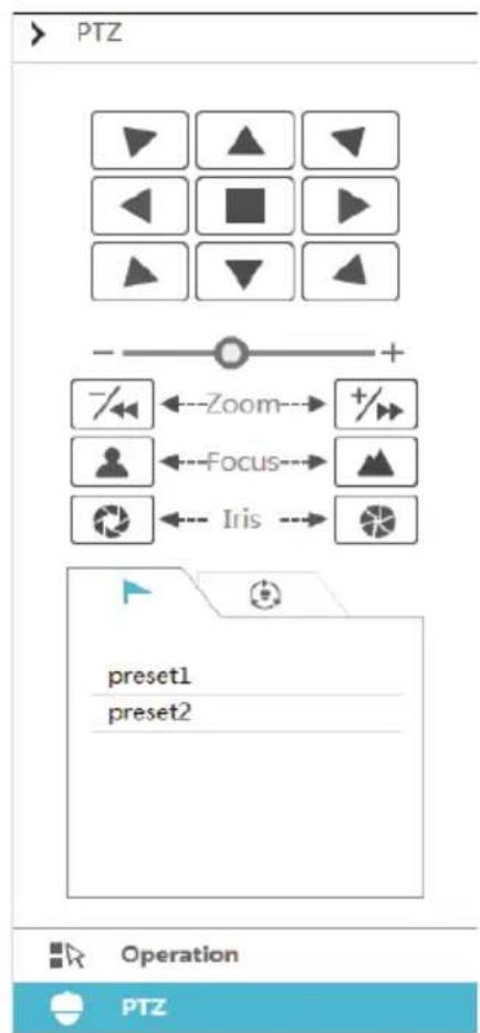
flowchart
graph TD
    A["Start"] --> B["PTZ"]
    B --> C1["Control: ▶, ▲, ▼, ▶, ▶, ▶, ▶"]
    C1 --> D1["Zoom: -/← Zoom→ +/→"]
    D1 --> E1["Focus: ●, ←→"]
    E1 --> F1["Iris: ◯, ←→"]
    F1 --> G1["Operation: preset1, preset2"]
Click one camera window in the preview area and then click Main Stream to set the camera's live preview stream and record stream to main stream in manual record mode; click Sub-stream to set the camera's live preview stream and record stream to sub stream. In sub stream tab, set the resolution, FPS and bitrate and then click "Apply" to save the settings.
Operation panel introduction:
| Button Meaning | |
| Click to take snapshot. | |
| Click to start recording; click it again to stop recording. | |
| Click to zoom in the image of the camera and then drag the mouse on the camera image to view the hidden area. | |
| Click to zoom out the image of the camera. | |
| The 3D zoom in function is designed for PTZ's Click the button and then drag the image to zoom in or zoom out the image; click the image on different areas to view the image of the dome, Omni-directionally. | |
| Click to close the preview camera. | |
 | Click to enable audio and then drag the slider bar to adjust the volume. You can listen to the cameras audio by enabling audio. |
PTZ panel introduction:
| Button Meaning | |
 | Click ▲ / ▼ / ▼ / ▼ / ▲ / ▲ / ▲ / ▲ to rotate the dome; click ▪ to stop rotating the dome. |
 | Drag the slider to adjust the rotating speed of dome. |
 | Click +/→ / → to zoom in/out camera image. |
 | Click ▲ / ▲ to increase/ decrease the focal length. |
 | Click ○ / ○ to increase/decrease the iris of the dome. |
 | Click it to view the preset list and then click the button in the list to call the preset. |
| [7AHC] | Click it to view the cruise list and then click the corresponding buttons in the list to start or stop the cruise. |
11.10.2 Remote Playback
Click "Playback" in the remote interface to go to the playback interface.
☐ Check the record event types and cameras on the left panel. Set the record date on the calendar beside the time scale.
☐ Click Search to search the record data and then click Play or directly click the time scale to play the recording.
The operation of the playback time scale is similar to that of the time scale in the main program of the NVR. Please refer to 8.2 Playback Interface Introduction for details.
Introduction of playback control buttons:
| Button Meaning | |
| Stop button. | |
| Rewind button. Click to play video backward. | |
| Play button. Click to play video forward. | |
| Pause button. | |
| Deceleration button. Click to decrease the playing speed. | |
| Acceleration button. Click to increase the playing speed. | |
| Previous frame button. It works only when forward playing is paused in single screen mode. | |
| Next frame button. It works only when forward playing is paused in single screen mode. | |
 | Click ⏻ to step backward 30s and click ⚠ to step forward 30s. |
 | Backup start time button. Click the time scale and then click to set the backup start time. |
 | Backup end time button. Click the time scale and then click to set the backup end time. |
| [ZX4W] | Backup button. |
| [A00X] | Backup tasks button. Click to view the backup status. |
| Event list button. Click to view the event record of manual/schedule/sensor/motion. | |
11.10.3 Remote Backup
Click “Backup” in the remote interface to go to the backup interface. You can back up the record by event or by time.
By Event
Check the record type on the left side of the interface and then click to set the start time and end time; check the cameras and then click on the right side to search the record (the searched recorded data will be displayed in the list); check the recorded data in the list and then click “Backup” button to backup the record.
By Time
Click 📄 to set the start time and end time on the left side of the interface; check the cameras and then click 📅 on the right side to backup the recording.
View Backup Status: Click “Backup Status” to view the backup status. Click “Pause” to pause the backup; click “Resume” to continue the backup; click “Delete” to delete the task.
11.10.4 Remote Configuration
Click “Function Panel” in the remote interface and then configure the camera, record, alarm, disk, network, account and authority and system of the NVR remotely. All of these settings are similar to that of the NVR. See the configurations of the NVR for details.
Appendix A FAQ
Q1. Why can't I find the HDD?
a. Please check the power and SATA data cables of the HDD to make sure they are well connected.
b. For some NVRs with the 1U or small 1U case, the power of the adapter may be not enough for operating them. Please use the power adaptor supplied along with the NVR.
c. Please make sure the HDDs are compatible with the NVR. See Appendix C Compatible Device List for details.
d. The HDD could have gone bad. install a new one.
Q2. Why are there no images in some or all of the camera windows?
a. Please make sure the resolutions of the cameras are supported by the NVR.
b. Please make sure the network cables of the IP camera and NVR are both connected properly and the network parameters are set correctly.
c. Please make sure the network and the switch both work normally.
Q3. The monitor has no image after turning on the NVR.
a. Please make sure the monitor, HDMI or VGA cables are good and well connected.
b. Please make sure the monitor supports the resolution of 1280*1024, 1920*1080 or 3840*2160 (4K*2K). The NVR cannot self adapt to the monitor of which the resolution is lower than 1280*1024, the monitor will remind you that the screen resolution is not supported by the NVR or just have no display. Please change the monitor to 1280*1024, 1920*1080 or 3840*2160 resolution before turning on the NVR.
Q4. Forget the passwords?
a. The password of the super administrator admin can be reset through “Edit Security Question” function.
Click “Edit Security Question” button in the login window and then enter the corresponding answer of the selected question in the popup window, the password of admin will be reset to 123456 by default. If you forget the answer of the question, this way will be invalid, please contact your dealer for help.
b. The passwords of other users can be reset by the super administrator admin, please refer to 10.1.2 Edit User for details.
Q5. The NVR will not hold the maximum number of IP cameras?
Take the 16 CH NVR as an example. Some 16 CH NVR support a maximum of 120Mbps bandwidth input. Refer to the picture below. The remaining bandwidth should be larger than the bandwidth of the IP camera you want to add, or it would fail to add the IP camera. You should lower the added cameras' bitrate to release the bandwidth. It is recommended to add cameras by "Quickly Add" for batch adding.
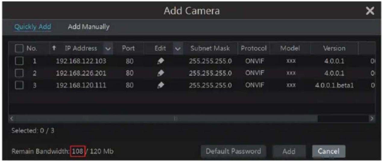
Q6. The IP camera which connects to the PoE port of the NVR cannot be displayed automatically in the camera list, why?
a. Please check whether the resource of the PoE port is occupied by another IP camera that is added through network.
- Take the 16 CH NVR with 8 PoE ports as an example. The resource distribution of the 16 CH IP cameras is shown in the picture below.
| CH1 | CH2 | CH3 | CH4 | CH5 | CH6 | CH7 | CH8 | CH9 | CH10 | CH11 | CH12 | CH13 | CH14 | CH15 | CH16 |
| POE-1 | POE-2 | POE-3 | POE-4 | POE-5 | POE-6 | POE-7 | POE-8 |
When you add IP cameras through network, the IP cameras will occupy the resource from CH1, CH2, CH3, CH4... by the adding sequence; if you directly connect the IP cameras to the PoE ports of the NVR, the IP cameras will occupy the resource from CH9 to CH16 according to the number of the PoE port each IP camera is connecting to.
Supposing that 12 CH IP cameras have been added to the NVR through network and no IP camera has been directly connected to the PoE port. The 12 CH IP cameras occupy the 8 network resources from CH1 to CH8 and 4 PoE resources from CH9 to CH12 which are supposed to be occupied by connecting the IP cameras directly. In this situation, if you directly connect one IP camera to PoE5, PoE6, PoE7 or PoE8, the IP camera will be displayed in the camera list automatically; if you connect it to PoE1, PoE2, PoE3 or PoE4, it won't be displayed in the camera list by showing resource conflict; if you just need to connect it to PoE1, PoE2, PoE3 or PoE4, you should first delete the IP camera which occupies the PoE port resource and then reconnect it to the PoE port.
- Take the 8 CH NVR with 8 PoE ports as another example. The resource distribution of the 8 CH IP cameras is shown in the picture below and the adding rules of the IP cameras are similar to the rules mentioned in the above. Please refer to the above for details.
| CH1 | CH2 | CH3 | CH4 | CH5 | CH6 | CH7 | CH8 |
| POE-1 | POE-2 | POE-3 | POE-4 | POE-5 | POE-6 | POE-7 | POE-8 |
The internal Ethernet port and the IP camera which directly connects to the PoE port through
ONVIF protocol should be in the same network segment, or it will fail to add the IP camera. Log into the IP camera's web client and then enable DHCP (obtain an IP address automatically); or manually change the IP address of the IP camera to make it in the same network segment with the internal Ethernet port.
b. Check whether the number of the added IP camera is the maximum.
If the number of the added IP camera is the maximum, the system will show you the message that the IP camera number is beyond the maximum when you directly connect another IP camera to the available PoE port and thus you will fail to add the IP camera.
Q7. The IP camera which directly connects to the PoE port of the NVR through ONVIF protocol is shown in the camera list, but there is no image output, why?
Please make sure the username and password of the IP camera are correct. The IP camera's username and password can be modified through the two ways mentioned below.
① Click “Edit Camera” in the Camera module of the setup panel to go to the interface as shown below. Click 📋 to modify the username and password of the IP camera (input the correct username and password of the IP camera in the popup window and then click “OK” button).
![Edit Camera Edit Camera Group Search Camera No. Camera Name ↑ IP Address Port Status Protocol Model Preview Edit Delete 1 [POE3]IP Camera1 10.151.151.20 80 Offline ONVIF xxx 2 IP Camera2 192.168.12.40 80 Online ONVIF xxx 3 IP Camera3 192.168.12.152 80 Online ONVIF xxx 4 IP Camera4 192.168.12.41 80 Online ONVIF xxx 5 IP Camera5 192.168.12.153 80 Offline ONVIF xxx 6 IP Camera6 192.168.12.154 80 Online ONVIF xxx 7 IP Camera7 192.168.12.155 80 Online ONVIF xxx 8 IP Camera8 192.168.12.156 80 Online ONVIF xxx 9 IP Camera9 192.168.12.157 80 Online ONVIF xxx 10 [POE1]IP Camera10 192.168.12.158 80 Online ONVIF xxx Remain Bandwidth: 60 / 120 Mb](/content/2026/06/1213934/images/e789440a27a92ab0217c591084df4cf51a04088905b667b4df214d26dc07bc24.jpg)
② Go to the live preview interface and then click in the preview window of the IP camera to edit the IP camera's username and password.
Q8. The system cannot record, why?
a. Make sure the HDD was formatted prior to use.
b. The record schedule has not been set in manual record mode. Please refer to 7.3.2 Record Schedule Configuration for details.
c. HDD is full and thus the NVR is not able to record. Check HDD information from Disk Management and if required, please enable the recycle function (please see 7.1.2 Advanced Configuration for details).
d. There is no disk but cameras in the disk group, so please add at least one disk to the group. Refer to 7.5.1 Storage Mode Configuration for details.
e. The HDD could have gone bad. Please install another one.
Q9. Fail to access the NVR remotely through IE.
a. Please make sure the IE version is IE8 or above.
b. Please check whether the PC has enabled the firewall or antivirus software. Please try to access the NVR again after you disable the firewall and stop the antivirus software.
c. Allow & block list may have been set in Account and Authority setting. The PC of which the IP address is in the block list or out of the allow list cannot access the NVR remotely.
Q10. ActiveX control cannot be downloaded. How can I do?
a. IE browser blocks ActiveX control. Please do setup as per the steps mentioned below.
Open IE browser. Click →Internet Options.
□ Select Security→Custom Level. Refer to Fig 10-1.
□ Enable all the sub options under "ActiveX controls and plug-ins". Refer to Fig 10-2.
Then click "OK" to finish setup.
b. Other plug-ins or anti-virus may block ActiveX. Please disable or do the required settings.
Fig 10-1
Fig 10-2
Q11. How to play the backup file?
a. Recording backed up by NVR: insert the USB device in which the recorded backup files is saved to the USB interface of the PC and then open the USB device path. The recording can be backed up in the private format or AVI format by NVR.
- If you select the private format when backing up recording by NVR, a RPAS compression package will be backed up to the USB device automatically along with the record data. Uncompress the “RPAS.zip” and then click “RPAS.exe” to set up RPAS. After the setup is completed, open RPAS player and then click “Open Folder” button in the middle of the interface to select the recorded data. Refer to Fig 11-1.
Select camera in the resource tree on the left side of the interface to play the camera recording. Click 🖼️ on the tool bar under the camera image to enable audio. Refer to Fig 11-2.
Note: The recording will not have audio output if you disable the audio when recording by NVR. Please see 7.1.1 Mode Configuration and 7.2 Encode Parameters Setting for details.
- If you select the AVI format when backing up recording by NVR, the record backup data can be played by a video player which supports this format.
b. Recording backed up through web. The record can only be backed up with AVI format through web. The recording can be backed up to PC and played by a video player which supports this format.
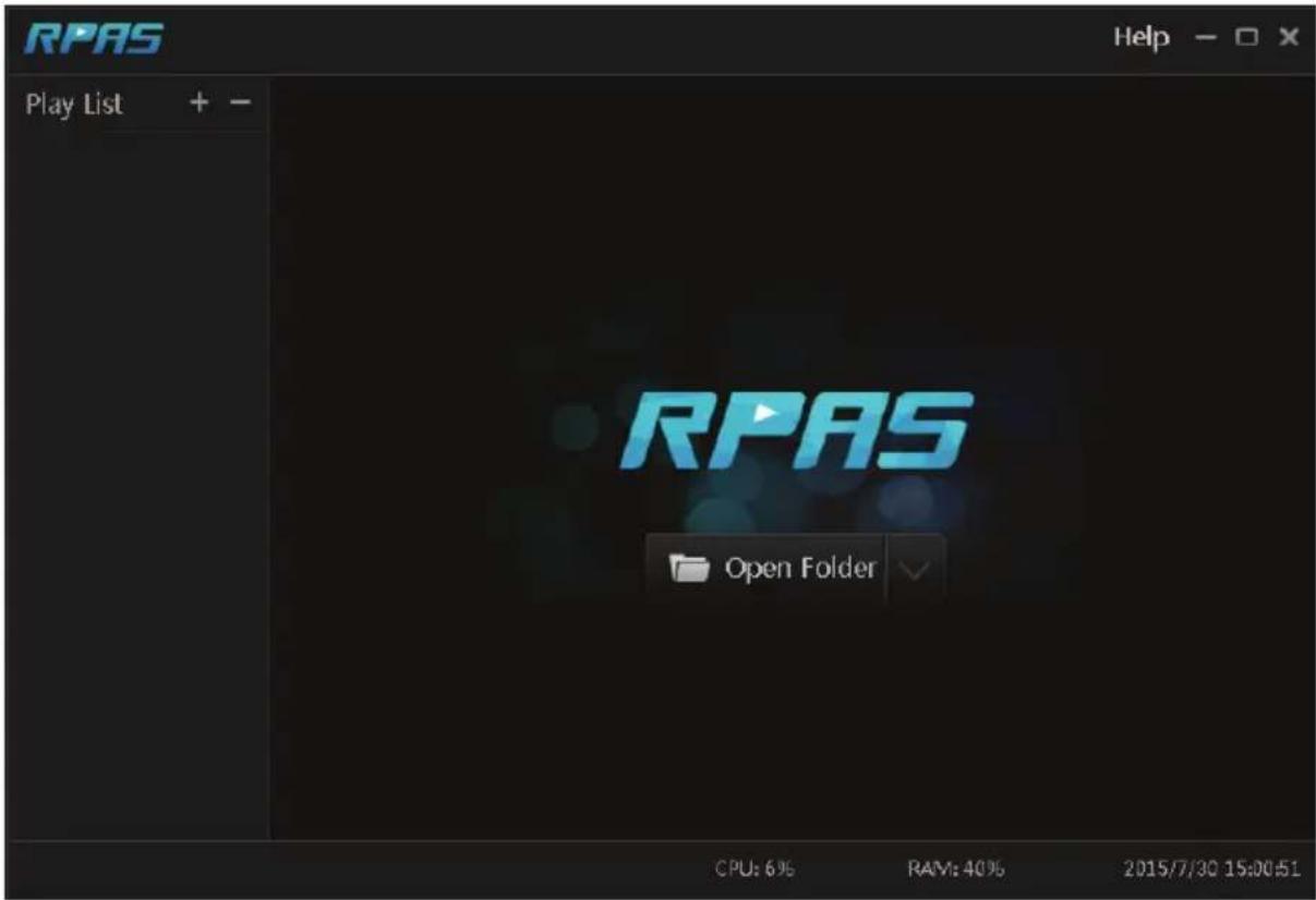
Fig 11-1

Fig 11-2
Appendix B Compatible Device List
Compatible HDD list
| Brand and Series | Capacity | |
| Seagate | Barracuda Series | 500GB /1TB /2TB /3TB |
| SV35 Series (recommended) | 1TB /2TB /3TB | |
| Surveillance HDD Series (recommended) | 1TB /2TB /3TB /4TB /6TB | |
| Western Digital | Blue Series 500GB /1TB | |
| Green Series | 2TB /3TB /4TB | |
| Purple Series (recommended) | 1TB /2TB /3TB /4TB /6TB | |
Compatible USB mobile device
| Brand Capacity | |
| SSK 2GB | |
| Netac 4GB | |
| Kingston | 2GB/8GB/16GB/32GB |
| Aigo 2GB | |
| Smatter vider 1GB | |
| SanDisk | 4GB/8GB/16GB/32GB |
VT-TNR414P Specifications
| Video Input / Resolution | 4 IP Channels up to 8 MegaPixel |
| Main Monitor Output | 1 x 4K HDMI / 1 x 1080P VGA |
| Multi Operation | Pentaplex: Live Display / Record / Playback / Backup / Remote Acess |
| Recording Compression | H.265 / H.264 |
| OS | Embedded Linux |
| Recording | 120fps (30fps per channel) |
| Audio over IP Inputs | 4 (1 Audio Channel per IP Camera over IP) |
| Local Audio In/Out | IN: RCA x 1CH / OUT: RCA x 1CH |
| Two-Way Audio | YES |
| Encode | CBR |
| Quality Levels | 11 level (According to Bit Rate) |
| Recording Modes | Manual / Timer / Motion / Sensor |
| File Management | Reserving time, Redundancy, Dual stream recording |
| Local Playback | 4CH |
| Search | Time sliced image search, Time/Calendar search, Event (Motion, External alarm), Tag search |
| Alarm Modes | Sensor, Motion, Video loss, IP conflict, Disk error, Illegal access, Network disconnection |
| Alarm Inputs | IP Camera Dependent (No Local Input) |
| Alarm Triggering | Record, Snap, PTZ move, Alarm out, E-mail, etc |
| Network Interface | RJ45 x 1 |
| POE ports | RJ45 x 4, with POE |
| PoE Standard | 802.3af 15W max per port |
| Total PoE Budget | 50W all ports |
| Bit Rate (Per Camera) | 512Kbps ~ 10 Mbps (Adjustable) |
| Total Bandwidth | 50Mbps Incoming / 50Mbps Outgoing |
| Dual-stream | Individual Network Video Stream and local recording stream, set separately |
| Network Protocols | TCP/IP, UDP, DHCP, ONS, PPPOE, DONS, Email, UPNP, NAT, Telnet |
| Internet-streaming | Total 28 task resource (Local+Remote) 4 CH IE playback |
| Remote Viewing | CMS / Web Browser / Mobile Platforms |
| Remote Users | 10 Simultaneous Online Users |
| Backup | Network, USB |
| SATA HDD | SATA x 1, max to 8TB each |
| PTZ Protocol | Through Network |
| USB | USB 2.0 x 2 (for mouse and USB backup device) |
| Power Consumption | ≤ 5W (Without HDD) |
| Power Supply | 48V/2.5A |
| Working Environment | 32°~122°F @ 10% ~ 90% RH |
| Weight | 4.41lbs (2kg) |
| Dimensions (WxHxD) | 10.43" x 1.77" x 8.07" (265mm×45mm×205mm) |
VT-TNR818P Specifications
| Video Input / Resolution | 8 IP Channels up to 8 MegaPixel |
| Main Monitor Output | 1 x 4K HDMI / 1 x 1080P VGA |
| Multi Operation | Pentaplex: Live Display / Record / Playback / Backup / Remote Acess |
| Recording Compression | H.265 / H.264 |
| OS | Embedded Linux |
| Recording | 240fps (30fps per channel) |
| Audio over IP Inputs | 8 (1 Audio Channel per IP Camera over IP) |
| Local Audio In/Out | IN: RCA x 1CH / OUT: RCA x 1CH |
| Two-Way Audio | YES |
| Encode | CBR |
| Quality Levels | 11 level (According to Bit Rate) |
| Recording Modes | Manual / Timer / Motion / Sensor |
| File Management | Reserving time, Redundancy, Dual stream recording |
| Local Playback | 8CH |
| Search | Time sliced image search, Time/Calendar search, Event (Motion, External alarm), Tag search |
| Alarm Modes | Sensor, Motion, Video loss, IP conflict, Disk error, Illegal access, Network disconnection |
| Alarm Inputs | IP Camera Dependent (No Local Input) |
| Alarm Triggering | Record, Snap, PTZ move, Alarm out, E-mail, etc |
| Network Interface | RJ45 x 1 |
| POE ports | RJ45 x 8, with POE |
| PoE Standard | 802.3af 15W max per port |
| Total PoE Budget | 100W all ports |
| Bit Rate (Per Camera) | 512Kbps ~ 10 Mbps (Adjustable) |
| Total Bandwidth | 50Mbps Incoming / 50Mbps Outgoing |
| Dual-stream | Individual Network Video Stream and local recording stream, set separately |
| Network Protocols | TCP/IP, UDP, DHCP, DNS, PPPOE, DDNS, Email, UPNP, NAT, Telnet |
| Internet-streaming | Total 33 task resource (Local+Remote) 8 CH IE playback |
| Remote Viewing | CMS / Web Browser / Mobile Platforms |
| Remote Users | 10 Simultaneous Online Users |
| Backup | Network, USB |
| SATA HDD | SATA x 1, max to 8TB each |
| PTZ Protocol | Through Network |
| USB | USB 2.0 x 2 (for mouse and USB backup device) |
| Power Consumption | ≤ 5W (Without HDD) |
| Power Supply | 48V/2.5A |
| Working Environment | 32°~122°F @ 10% ~ 90% RH |
| Weight | 4.85lbs (2.2kg) |
| Dimensions (WxHxD) | 10.43" x 1.77" x 8.07" (265mm×45mm×205mm) |
VT-TNR1616P Specifications
| Video Input / Resolution | 16 IP Channels up to 8 MegaPixel |
| Main Monitor Output | 1 x 4K HDMI / 1 x 1080P VGA |
| Multi Operation | Pentaplex: Live Display / Record / Playback / Backup / Remote Acess |
| Recording Compression | H.265 / H.264 |
| OS | Embedded Linux |
| Recording | 480fps (30fps per channel) |
| Audio over IP Inputs | 16 (1 Audio Channel per IP Camera over IP) |
| Local Audio In/Out | IN: RCA x 1CH / OUT: RCA x 1CH |
| Two-Way Audio | YES |
| Encode | CBR |
| Quality Levels | 11 level (According to Bit Rate) |
| Recording Modes | Manual / Timer / Motion / Sensor |
| File Management | Reserving time, Redundancy, Dual stream recording |
| Local Playback | 16 CH |
| Search | Time sliced image search, Time/Calendar search, Event (Motion, External alarm), Tag search |
| Alarm Modes | Sensor, Motion, Video loss, IP conflict, Disk error, Illegal access, Network disconnection |
| Alarm Inputs | IP Camera Dependent (No Local Input) |
| Alarm Triggering | Record, Snap, PTZ move, Alarm out, E-mail, etc |
| Network Interface | RJ45 x 1 |
| POE ports | RJ45 x 16 with POE |
| PoE Standard | 802.3af 15W max per port |
| Total PoE Budget | 200W (Total) |
| Bit Rate (Per Camera) | 512Kbps ~ 10 Mbps (Adjustable) |
| Total Bandwidth | 112Mbps Incoming / 112Mbps Outgoing |
| Dual-stream | Individual Network Video Stream and local recording stream, set separately |
| Network Protocols | TCP/IP, UDP, DHCP, DNS, PPPOE, DONS, Email, UPNP, NAT, Telnet |
| Internet-streaming | Total 33 task resource (Local+Remote) 16 CH IE playback |
| Remote Viewing | CMS / Web Browser / Mobile Platforms |
| Remote Users | 10 Simultaneous Online Users |
| Backup | Network, USB |
| SATA HDD | SATA x 2, max to 8TB each |
| PTZ Protocol | Through Network |
| USB | USB 2.0 x 2 (for mouse and USB backup device) |
| Power Consumption | ≤ 15W (Without HDD) |
| Power Supply | 48 VDC |
| Working Environment | 32°~122°F @ 10% ~ 90% RH |
| Dimensions (WxHxD) | 15" x 1.75" x 11" (381 x 44.45 x 25.4mm) |
VT-TNR3216P Specifications
| Video Input / Resolution | 32 IP Channels up to 8 MegaPixel |
| Main Monitor Output | 1 x 4K HDMI / 1 x 1080P VGA |
| Multi Operation | Pentaplex: Live Display / Record / Playback / Backup / Remote Acess |
| Recording Compression | H.265 / H.264 |
| OS | Embedded Linux |
| Recording | 960fps (30fps per channel) |
| Audio over IP Inputs | 32 (1 Audio Channel per IP Camera over IP) |
| Local Audio In/Out | IN: RCA x 1CH / OUT: RCA x 1CH |
| Two-Way Audio | YES |
| Encode | CBR |
| Quality Levels | 11 level (According to Bit Rate) |
| Recording Modes | Manual / Timer / Motion / Sensor |
| File Management | Reserving time, Redundancy, Dual stream recording |
| Local Playback | 16CH |
| Search | Time sliced image search, Time/Calendar search, Event (Motion, External alarm), Tag search |
| Alarm Modes | Sensor, Motion, Video loss, IP conflict, Disk error, Illegal access, Network disconnection |
| Alarm Inputs | 16CH Local Input + 1 Channel per IP Camera |
| Alarm Output | 4CH |
| Alarm Triggering | Record, Snap, PTZ move, Alarm out, E-mail, etc |
| Network Interface | RJ45 x 1 |
| POE ports | RJ45 x 16, with POE |
| PoE Standard | 802.3af 15W max per port |
| Total PoE Budget | 150W all ports |
| Bit Rate (Per Camera) | 512Kbps ~ 10 Mbps (Adjustable) |
| Total Bandwidth | 256Mbps Incoming / 256Mbps Outgoing |
| Dual-stream | Individual Network Video Stream and local recording stream, set separately |
| Network Protocols | TCP/IP, UDP, DHCP, DNS, PPPOE, DDNS, Email, UPNP, NAT, Telnet |
| Internet-streaming | Total 95 task resource (Local+Remote) 16 CH IE playback |
| Remote Viewing | CMS / Web Browser / Mobile Platforms |
| Remote Users | 10 Simultaneous Online Users |
| Backup | Network, USB |
| SATA HDD | SATA x 8, max to 10TB each |
| RS485 | RS485 x 2 (for PTZ and Keyboard) |
| PTZ Protocol | Through Network or RS485 (Pelco D / Pelco P) |
| USB | USB 2.0 x 1 + USB 3.0 x 1 (for mouse and USB backup device) |
| Power Consumption | ≤ 15W (Without HDD) |
| Power Supply | AC 110/220V (ATX 300W) |
| Working Environment | 32°~122°F @ 10% ~ 90% RH |
| Weight | 19.62lbs (8.9kg) |
| Dimensions (WxHxD) | 16.93" x 3.54" x 17.72" (430 x 90 x 450mm) |
VT-TNR6480 Specifications
| Video Input / Resolution | 64 IP Channels up to 8 MegaPixel |
| Main Monitor Output | 1 x 4K HDMI / 1 x 1080P HDMI / 1 x 1080P VGA |
| Multi Operation | Pentaplex: Live Display / Record / Playback / Backup / Remote Acess |
| Recording Compression | H.265 / H.264 |
| OS | Embedded Linux |
| Recording | 1920fps (30fps per channel) |
| Audio over IP Inputs | 64 (1 Audio Channel per IP Camera over IP) |
| Local Audio In/Out | IN: RCA x 1CH / OUT: RCA x 1CH |
| Two-Way Audio | YES |
| Encode | CBR |
| Quality Levels | 11 level (According to Bit Rate) |
| Recording Modes | Manual / Timer / Motion / Sensor |
| File Management | Reserving time, Redundancy, Dual stream recording |
| Local Playback | 16CH |
| Search | Time sliced image search, Time/Calendar search, Event (Motion, External alarm), Tag search |
| Alarm Modes | Sensor, Motion, Video loss, IP conflict, Disk error, Illegal access, Network disconnection |
| Alarm Inputs | 8CH Local Input + 1 Channel per IP Camera |
| Alarm Output | 4CH |
| Alarm Triggering | Record, Snap, PTZ move, Alarm out, E-mail, etc |
| Network Interface | RJ45 x 2 |
| Bit Rate (Per Camera) | 512Kbps ~ 10 Mbps (Adjustable) |
| Total Bandwidth | 320Mbps Incoming / 320Mbps Outgoing |
| Dual-stream | Individual Network Video Stream and local recording stream, set separately |
| Network Protocols | TCP/IP, UDP, DHCP, DNS, PPPOE, DDNS, Email, UPNP, NAT, Telnet |
| Internet-streaming | Total 95 task resource (Local+Remote) 16 CH IE playback |
| Remote Viewing | CMS / Web Browser / Mobile Platforms |
| Remote Users | 10 Simultaneous Online Users |
| Backup | Network, USB |
| SATA HDD | SATA x 8, max to 10TB each |
| RS485 | RS485 x 2 (for PTZ and Keyboard) |
| PTZ Protocol | Through Network or RS485 (Pelco D / Pelco P) |
| USB | USB 2.0 x 1 + USB 3.0 x 1 (for mouse and USB backup device) |
| Power Consumption | ≤ 15W (Without HDD) |
| Power Supply | AC 110/220V (ATX 250W) |
| Working Environment | 32°~122°F @ 10% ~ 90% RH |
| Weight | 19.18Ics (8.7kg) |
| Dimensions (WxHxD) | 16.93" x 3.54" x 17.72" (430 x 90 x 450mm) |
LIMITED PRODUCT WARRANTY
VITEK products carry a three (3) year limited warranty. VITEK warrants to the purchaser that products manufactured by VITEK are free of any rightful claim of infringement or the like, and when used in the manner intended, will be free of defects in materials and workmanship for a period of three (3) years, or as otherwise stated above, from the date of purchase by the end user. This warranty is nontransferable and extends only to the original buyer or end user customer of a VITEK Authorized Reseller.
The product must have been used only for its intended purpose, and not been subjected to damage by misuse, willful or accidental damage, caused by excessive voltage or lightning.
The product must not have been tampered with in any way or the guarantee will be considered null and void.
This guarantee does not affect your statutory rights.
Contact your local VITEK Reseller should servicing become necessary.
VITEK makes no warranty or guarantee whatsoever with respect to products sold or purchased through unauthorized sales channels. Warranty support is available only if product is purchased through a VITEK Authorized Reseller.
- FEATURES:
- CAUTION
- Contents
- Contents....2
- Introduction......6
- Basic Operation Guide .... 13
- Wizard & Main Interface....17
- Camera Management 27
- Add/Edit Camera Group....29
- Live Preview Introduction 30
- Preview Image Configuration....35
- PTZ 39
- Record & Disk Management 44
- Playback & Backup....52
- Alarm Management....62
- Account & Permission Management 68
- Device Management 73
- Introduction
- Summary
- Features
- Basic Functions
- Live Preview
- Disk Management
- Record Configuration
- Record Playback
- Record Backup
- Alarm Management
- Network Functions
- Other Functions
- Front Panel Descriptions
- Rear Panel Descriptions
- Connections
- - Video Connections
- ● Audio Connections
- - Alarm Connections
- - RS485 Connection
- Basic Operation Guide
- Startup & Shutdown
- Startup
- Shutdown
- By remote controller:
- By mouse:
- Remote Control
- Mouse Control
- Mouse control in Live & Playback interface
- Mouse control in text-input
- Text-input Instruction
- Common Button Operation
- Wizard & Main Interface
- Startup Wizard
- Note:
- Main Interface
- Main Interface Introduction
- Setup Panel
- Main Functions
- Camera
- Record
- Disk
- > Alarm
- Network
- Account and Authority
- System
- Camera Management
- Add/Edit Camera
- Add Camera
- ▶ Quickly Add
- Add Manually
- Edit Camera
- Add/Edit Camera Group
- Add Camera Group
- Edit Camera Group
- Live Preview Introduction
- Preview Interface Introduction
- Preview Mode
- Preview By Display Mode
- ➢ Add Display Mode
- Method One:
- Method Two:
- Edit Display Mode
- Quick Sequence View
- Camera Group View In Sequence
- Camera Group for details).
- Scheme View In Sequence
- Add Scheme
- Configure Scheme
- Start Sequence View
- Preview Image Configuration
- OSD Settings
- Image Settings
- Mask Settings
- Image Adjustment
- ➢ Image Adjustment
- ➢ Lens Control (camera dependent)
- PTZ
- PTZ Control Interface Introduction
- ▶ Analog Joystick Control
- 3D Control
- ▶ Advanced 3D Control
- Preset Setting
- Cruise Setting
- Preset Setting
- ▶ Add preset
- Edit preset
- Delete Preset
- Cruise Setting
- Add Cruise
- Edit Cruise
- Delete Cruise
- Record & Disk Management
- Record Configuration
- Mode Configuration
- Auto Mode
- ▶ Manual Mode
- Advanced Configuration
- Encode Parameters Setting
- Schedule Setting
- Add Schedule
- ➢ Set Day Schedule
- ➢ Set Week Schedule
- Record Schedule Configuration
- Record Mode
- Manual Recording
- Timing Recording
- Motion Based Recording
- Sensor Based Recording
- Disk Management
- Storage Mode Configuration
- View Disk and S.M.A.R.T. Information
- Playback & Backup
- Instant Playback
- Playback Interface Introduction
- Record Search & Playback
- Search & Playback by Time-sliced Image
- Time Slice Mode Selecting:
- Search & Playback by Time
- Search & Playback by Event
- Search & Playback by Tag
- Backup
- Backup by Time
- Backup by Event
- Image Management
- View Backup Status
- Alarm Management
- Sensor Alarm
- Motion Alarm
- Motion Configuration
- Motion Alarm Handling Configuration
- Exception Alarm
- Exception Handling Settings
- IPC Offline Settings
- Alarm Event Notification
- Alarm-out
- Display
- Buzzer
- Manual Alarm
- View Alarm Status
- Account & Permission Management
- Account Management
- Add User
- Edit User
- ➢ Edit Security Question
- Modify Password
- ▶ Recover Password
- Edit User
- User Login & Logout
- Permission Management
- Add Permission Group
- Edit Permission Group
- Black and White List
- Device Management
- Network Configuration
- TCP/IPv4 Configuration
- IP Address Settings
- Internal Ethernet Port Introduction:
- ▶ PPPoE Settings
- Port Configuration
- DDNS Configuration
- E-mail Configuration
- UPnP Configuration
- NAT Configuration
- View Network Status
- Basic Configuration
- Common Configuration
- Date and Time Configuration
- Factory Default
- Device Software Upgrade
- Backup and Restore
- - Backup
- - Recover
- View Log
- View System Information
- Web LAN Access
- Web WAN Access
- NAT Access
- ▶ PPPoE Access
- Router Access
- Web Remote Control
- Remote Preview
- Start Preview
- ▶ Left Panel Introduction
- • View Camera
- • View Group
- Tool Bar Introduction
- Right Panel Introduction
- Remote Playback
- Remote Backup
- By Event
- By Time
- Remote Configuration
- Appendix A FAQ
- Q1. Why can't I find the HDD?
- Q2. Why are there no images in some or all of the camera windows?
- Q3. The monitor has no image after turning on the NVR.
- Q4. Forget the passwords?
- Q5. The NVR will not hold the maximum number of IP cameras?
- Q6. The IP camera which connects to the PoE port of the NVR cannot be displayed automatically in the camera list, why?
- Q7. The IP camera which directly connects to the PoE port of the NVR through ONVIF protocol is shown in the camera list, but there is no image output, why?
- Q9. Fail to access the NVR remotely through IE.
- Q10. ActiveX control cannot be downloaded. How can I do?
- Q11. How to play the backup file?
- Appendix B Compatible Device List
- LIMITED PRODUCT WARRANTY
Brand : Vitek
Model : VT-TNR6480
Category : Network video recorder