PC-INJ-60W-B - Network adapter Barox - Free user manual and instructions
Find the device manual for free PC-INJ-60W-B Barox in PDF.

User questions about PC-INJ-60W-B Barox
0 question about this device. Answer the ones you know or ask your own.
Ask a new question about this device
Download the instructions for your Network adapter in PDF format for free! Find your manual PC-INJ-60W-B - Barox and take your electronic device back in hand. On this page are published all the documents necessary for the use of your device. PC-INJ-60W-B by Barox.
USER MANUAL PC-INJ-60W-B Barox
User Manual: PC-INJ-30-B Voltage Boosted Series
Version 1.2019
NOTE
Always make sure the total length of the TX cable DOES NOT exceed 100meter. Total length is defined as length A + length B

flowchart
graph LR
    PD["PD"] -->|A| Device["Device"]
    Device -->|B| RemoteSwitch["Remote Switch"]
    style PD fill:#000,stroke:#fff,color:#fff
    style RemoteSwitch fill:#000,stroke:#fff,color:#fff
    note bottom of PD: "Is A+ length P=1400 meters"
Length A + Length B < 100 meters
POE signal attenuates every meter, the built-in transformer allows the attenuation to reach 100 meters to follow IEEE802.3af/at standards. The higher quality PD you connect to, the more reliable the network will be. When connecting to a poor-quality PD, it cannot generate a strong enough signal for the remote switch. Always make sure you have a high-quality PD to perform your desired network.
Introduction
This rugged designed industrial PoE injector is equipped with a 30W PSE Port. The Injector can be powered by 24-56 VDC input voltage. With its multi-purpose design, it can also be Din-Rail or wall-mounted. It is an ideal unit for Mobile Base Station (BTS), IP surveillance, traffic monitoring and security applications in critical environments. It can tolerate -40°C to 75°C in harsh environments to perform a reliable network. This product has been rigorously tested in harsh environments for your security, transportation, and telco applications.
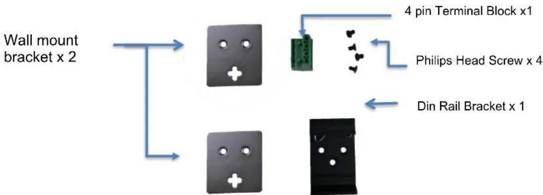
Installation package
This unit can be din-rail mounted or wall-mounted. Din-rail brackets and wall-mounted brackets are included.
flowchart
graph TD
    A["Wall mount bracket x 2"] --> B["Chip 1"]
    A --> C["Chip 2"]
    B --> D["Green Pin"]
    C --> E["Black Box"]
    D --> F["4 pin Terminal Block x1"]
    E --> G["Din Rail Bracket x 1"]
    F --> H["Philips Head Screw x 4"]
Power connection
This unit provides a 4 pin terminal block. It can be operated using 24-56VDC power source. Always make sure your input voltage is within this supported voltage range.
To connect power: This unit supports two power inputs. Follow the printed polarity for +V1-, +V2- and ground. Connect positive wires to V+, connect negative wires to V-, and connect a neutral wire to the ground screw.
+V1- is for power input one connection.
+V2- is for power input two connection.
Power connecting procedure:

text_image
+V1- +V2-STEP 1 – Take out 4 pin terminal block located in the included mounting kit package.
STEP 2 – Connect power wires to +V1- or +V2- with corresponding polarity. Connect the grounding wire to the ground screw.
STEP 3 – Plug into terminal block socket shown above. Polarity needs to match V+ and V-.
WARNING -- Always SHUT OFF power source to
connect power wire. WARNING -- Any exceeded input voltage will not make this unit function and may damage this unit.
LED indicator

flowchart
graph TD
    A["Industrial Gigabit POE Injector"] --> B["PW1 (Green)"]
    A --> C["Power"]
    A --> D["Mode A (Green)"]
    A --> E["Mode B (Green)"]
    A --> F["Power"]
    A --> G["Mode A (Green)"]
    H["Power"] --> I["Mode A (Green)"]
    J["Data"] --> K["Mode A (Green)"]
    L["Power"] --> M["Mode B (Green)"]
    N["Mode A (Green)"] --> O["Power"]
    P["Power"] --> Q["Mode A (Green)"]
    R["Mode A (Green)"] --> S["Power"]
    T["Power"] --> U["Mode A (Green)"]
    V["Power"] --> W["Mode A (Green)"]
    X["Power"] --> Y["Mode A (Green)"]
    Z["Power"] --> AA["Mode A (Green)"]
    AB["Power"] --> AC["Mode A (Green)"]
    AD["Power"] --> AE["Mode A (Green)"]
    AF["Power"] --> AG["Mode A (Green)"]
    AH["Power"] --> AI["Mode A (Green)"]
    AJ["Power"] --> AK["Mode A (Green)"]
    AL["Power"] --> AM["Mode A (Green)"]
    AN["Power"] --> AO["Mode A (Green)"]
    AP["Power"] --> AQ["Mode A (Green)"]
    AR["Power"] --> AS["Mode A (Green)"]
    AT["Power"] --> AU["Mode A (Green)"]
    AV["Power"] --> AW["Mode A (Green)"]
    AX["Power"] --> AY["Mode A (Green)"]
    AZ["Power"] --> BA["Mode A (Green)"]
    BB["Power"] --> BC["Mode A (Green)"]
    BD["Power"] --> BE["Mode A (Green)"]
    BF["Power"] --> BG["Mode A (Green)"]
    BH["Power"] --> BI["Mode A (Green)"]
    BJ["Power"] --> BK["Mode A (Green)"]
    BL["Power"] --> BM["Mode A (Green)"]
    BN["Power"] --> BO["Mode A (Green)"]
    BP["Power"] --> BQ["Mode A (Green)"]
    BR["Power"] --> BS["Mode A (Green)"]
    BT["Power"] --> BU["Mode A (Green)"]
    BV["Power"] --> BW["Mode A (Green)"]
    BX["Power"] --> BY["Mode A (Green)"]
    BZ["Power"] --> CA["Mode A (Green)"]
    CB["Power"] --> DA["Mode A (Green)"]
    DB["Power"] --> DBA["Mode A (Green)"]
    DC["Power"] --> DCB["Mode A (Green)"]
    DD["Power"] --> DDY["Mode A (Green)"]
    DX["Power"] --> DXB["Mode A (Green)"]
    DBX["Power"] --> DBY["Mode A (Green)"]
    DBZ["X"] --> DBY
    DBY["X"] --> DBY
Specifications
| IEEE Standard | IEEE 802.3 10Base-T EthernetIEEE 802.3u 100Base-TX Fast EthernetIEEE 802.3ab 1000Base-T Gigabit EthernetIEEE 802.3af for POEIEEE 802.3at for POE+ |
| Network Connector | 1xRJ-45 10/100/1000BaseT(X) Data1xRJ-45 10/100/1000BaseT(X) Data with PoE output power |
| Network Cable | UTP/STP above Cat.5e Cable |
| EIA/TIA-568 10-ohm (100m) | |
| Protocol | CSMA/CD |
| LED | PC-INJ-30-BA-12/ PC-INJ-30-B-95W-24PW1 (Green): ON-Power is detectedPW2 (Green): ON-Power is detectedMode A (Green): For End-Span PoE power 1,2,3,6Mode B (Green): Reserved |
| PC-INJ-30-B-60W-24PW1 (Green): ON-Power is detectedPW2 (Green): ON-Power is detectedMode A (Green): ON-End Span PD detectedMode B (Green): ON-Mid Span PD detected4 Pair (Amber): ON-60W PSE is in active modeOFF-30W PSE is in active mode | |
| PC-INJ-30-B-95W-BH-24PW1 (Green): ON-Power is detectedPW2 (Green): ON-Power is detectedPoE: ON-95W PSE is in active mode.OFF-PSE is in idle mode. | |
| POE Pin Assignment | Default: Mode A for Pin 1 (V-), 2 (V-), 3 (V+), 6 (V+)Mode B for Pin 4 (V+), 5 (V+), 7 (V-), 8 (V-) |
| Reverse polarity protection | Present |
| Overload current protection | Present |
| Power Supply | Redundant Dual DC 24V-56V power input |
| Power Consumption | 1 W@24/48 VDC full load, Without POE |
| POE power | Max total PoE power 36W |
| Removable Terminal Block | Provide 4 pin terminal blockWire range: 0.34mm^2 to 2.5mm^2Solid wire (AWG):12-24/14-22Stranded wire (AWG): 12-24/14-22Torque:5lb-In/0.5Nm/0.56NmWire Strip length: 7-8mm |
| Operating Temperature | -40°C to 75°C |
| Operating Humidity | 5% to 95% (Non-condensing) |
| Storage Temperature | -40°C to 85°C |
| MTBF (mean time between failure) | >500,000 hrs (MIL-HDBK-217F) at 25°C |
| Housing | Rugged Aluminum, IP30 Protection |
| Case Dimension (L X W X D) | 103.5 x 32 x 81.5 mm (L x W x D) |
| Installation mounting | DIN Rail and Wall Mount options included |
| Certifications | |
| Safety | UL 60950-1 |
| Safety | IEC EN60950-1 |
| EMC/EMS | CE, FCC, VCCI |
| EMI | FCC Part 15 Subpart B Class A |
| EN 60068-2-6 | Vibration |
| EN 60068-2-27 | Shock |
| EN 60068-2-32 | Free Fall |
Housing Dimension (mm)

text_image
52.10 21.75 13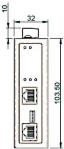
text_image
10 32 103.50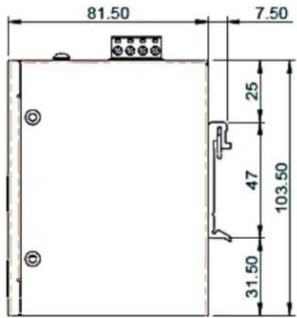
text_image
81.50 7.50 25 47 103.50 31.50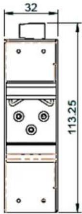
text_image
32 113.25
NOTE:
Housing dimension is for purpose of showing product Length, Width, Height, din-rail, and terminal block's position and dimension. Please reference the LED Indicator Page for correct port order.