DoorCom RDC-447 - Intercom Ritron - Free user manual and instructions
Find the device manual for free DoorCom RDC-447 Ritron in PDF.

User questions about DoorCom RDC-447 Ritron
0 question about this device. Answer the ones you know or ask your own.
Ask a new question about this device
Download the instructions for your Intercom in PDF format for free! Find your manual DoorCom RDC-447 - Ritron and take your electronic device back in hand. On this page are published all the documents necessary for the use of your device. DoorCom RDC-447 by Ritron.
USER MANUAL DoorCom RDC-447 Ritron
natural_image
Two wireless devices, one with a white base and the other a black device with a tall antenna (no visible text or symbols)
text_image
RITRON® WIRELESS SOLUTIONS DoorCom™ wireless intercom Owner's Manual
text_image
MADE IN THE USABasic Operation
RDC-SERIES DOORCOM™ MODELS.... i
SYSTEM COMPONENTS 1
OPTIONAL AND REPLACEMENT ACCESSORY EQUIPMENT....1
BRIEF FEATURE OVERVIEW 1
CONTROLS, CONNECTORS AND BUTTONS 2
FIGURE-1: RDC-1 AND R-SERIES CONTROLS AND CONNECTORS ..... 2
INITIAL SET-UP AND PROGRAMMING 2
Programmable Features 3
Field Programming
DOORCOM™ FIELD PROGRAMMING OVERVIEW 4
HOW TO READOUT CURRENT RADIO FREQUENCY & TONE CODES...... 5
FIGURE-2: HOW TO PLACE RADIO IN PROGRAM/READOUT MODE ..... 5
HOW TO FIELD PROGRAM FREQUENCY & TONE CODES....6
TABLE 1: PROGRAMMABLE FREQUENCY CODES....7 CANADIAN FREQUENCY CODES....8
TABLE 2: INTERFERENCE ELIMINATOR PROGRAMMABLE QC TONE CODES 8
Installation Instructions
RDC-1 SPEAKER INTERCOM BOX INSTALLATION INSTRUCTIONS...... 13
FIGURE-3: RDC-1 INSTALLATION 13
R-SERIES RADIO INSTALLATION INSTRUCTIONS 14
FIGURE-4: R-SERIES RADIO INSTALLATION.... 14
Operating Instructions
OPERATING THE DOORCOM ^TM WIRELESS INTERCOM......15
EXPOSURE TO RADIO FREQUENCY ENERGY 16
2013 FCC NARROWBAND MANDATE....16
OBSERVE CAUTION IN THE FOLLOWING ENVIRONMENTS TO MAXIMIZE THE LIFE OF YOUR RADIO EQUIPMENT 16
Licensing
FCC LICENSING....17
HOW TO OBTAIN AN FCC RADIO LICENSE 17
INDUSTRY CANADA REGULATIONS 17
SAFETY STANDARDS....16
Service....17
Warranty
RITRON, INC. LIMITED WARRANTY 18
RDC-SERIES DOORCOM™ MODELS
The radio transceiver's model number appears on the serial label located on the bottom-side of the metal enclosure.
VHF Models
RDC-147 VHF Wireless Intercom 2 Watts, 150 - 165 MHz
RDC-147M VHF MURS License-Free, Wireless Intercom, 2 Watts, 7 MURS Frequencies Only
RDC-147-CANADA VHF Wireless Intercom, Canada 2 Watts, 150.050-163.250 MHz
UHF Models
RDC-447 UHF Wireless Intercom 2 Watts, 450-470MHz
RDC-447-CANADA UHF Wireless Intercom, Canada 2 Watts, 450-470MHz
SYSTEM COMPONENTS
The DoorCom™ Wireless Intercom System provides 2-way, voice communication from delivery doors or other fixed locations to radio-equipped personnel in or around the facility. The rugged, all-metal, weather-resistant speaker intercom box can be mounted outdoors and is connected to the AC powered radio transceiver (indoors) with the 20ft connecting cable.
The DoorCom ^™ wireless intercom consists of 6 components.
- The R-Series Radio Transceiver
- RPS-1B - 110VAC AC Power Adaptor
- AFB-1545 - BNC Flexible Antenna
-
T-25 TORX bit
-
RDC-1, Stainless Steel, Speaker Intercom Box with 20 ft Connecting Cable attached (connects RDC-1 to radio)
- Wall Mount Bracket for radio transceiver
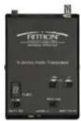
R-Series
Transceiver

RDC-1 w/20 ft Cable
PN#60201121

RPS-1B, 110VAC AC Adapter
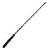
AFB-1545 Antenna

Mounting Bracket
OPTIONAL AND REPLACEMENT ACCESSORY EQUIPMENT
Available options include:
- AFB-1545 – Replacement, Molded Flex, Dual-Band Replacement Antenna
• RAM - 1545 – Optional, Magnet Mounted, Dual-Band Antenna w/BNC Connector - RPS-1B – Replacement, 110VAC to 12VDC Power Supply.
- JBS-MMK – Replacement, Mobile Mounting Kit.(Does not include screws to mount bracket to the wall)
- RDC-1 – Replacement, RDC-1, metal speaker intercom box. Includes PN#60201121 20ft cable, connects to radio.
- PN# 60201121 – 20ft Cable (RDC-1 to R-Series Transceiver) 2.5mm/3.5mm plug to spade lugs.
For additional information go to https://www ritron.com/doorcom-wireless-intercom and download pdf of the product brochure.
BRIEF FEATURE OVERVIEW
- Narrow Band FCC Compliant - The radio is compliant with the Federal Communication Commission's 2013 Narrow Band Mandate – go to www.ritron.com for more information.
- Field-Programming - Field-programming allows you to program specific features of the radio without a PC or special software.
- License-Free VHF MURS Model - The VHF RDC-147M model can be programmed from a list of 7 VHF MURS frequencies. These FCC frequencies are for business-only use and license-free.
- Licensed VHF and UHF Models - These models contain table frequencies that require an FCC license. They can also be PC programmed to "custom" frequencies making the DoorCom™ system compatible with an existing radio system or even radio repeaters.
- Speaker Volume - Field-settable in pre-set levels 0-9.
• Multi-Channel Pre-Sets - Up to 10 different pre-set channels -
Auto-ON When AC Power Applied - If AC power is removed from the radio i.e. a power failure, the radio will automatically turn ON, whenever AC power is restored.
-
Mode of Operation - The DoorCom™ Wireless Intercom can operate in one of two possible modes.
- "Automatic Turn-Off" Mode (Factory Default). The radio and speaker are OFF until the Call Button is pressed. Radio and speaker remain ON subject to activity on the channel and the reset timer setting (Default 10 seconds).
- "Intercom" Mode. The radio and speaker are always ON.
- DoorCom™ Time-Out Tone - A double tone alerts the visitor when the speaker has turned OFF. The same tone is transmitted to radio-equipped personnel to signal that the RDC-1 speaker has turned off and internal radio communication can now continue.
- Choose From Two Distinct Call Tones - "Door Bell" or "Ringing Tone".
- Interference Eliminator Codes - Quiet Call (QC) and Digital Quiet Call (DQC) codes can be programmed to eliminate other radio users not in your workgroup. For compatibility, new radios must be programmed with the same codes.
- Manager Lock - Prevents radio controls from being changed by unauthorized personnel.
- DTMF or Selcall Signaling - 3-7 digit DTMF or Selcall codes can be transmitted at the beginning of each message for radio identification.
CONTROLS, CONNECTORS & BUTTONS
1 Multi-Function LED Display
The LED display will indicate the current Operating Channel, the Speaker Volume setting (0-9), the Manager Lock condition and Field-Programming Information.
2 Channel Select Button
Press the Channel Button to advance to the next programmed channel.
3 Speaker Volume-Up/Down Buttons
Press the Volume Up Button to increase the volume, and press the Volume Down Button to decrease the volume. The volume level will be displayed momentarily in the channel display.
4 Speaker/Microphone Connection
The RDC-1 Speaker Intercom Box is connected to the radio here using the 2-PIN Connecting Cable PN#60201121.
5 Power Connector
The Power Connector on the top of the radio is used to connect power to the unit. Use the included 110VAC, RPS-1B AC Adapter.
6 BNC Antenna
The antenna radiates and receives radio signals. The included AFB-1545 Antenna connects to the BNC Connector on the top of the radio.
7 Radio Program Button
When the radio is in PTT Programming Mode, the Program Button is used to change channel information.
The channel display will display the programming information as it is entered.
8 RDC-1, Rugged, Stainless Steel Intercom Box
Tough, weather-resistant, all-metal enclosure protects against damage from weather and vandalism. Includes multiple mounting options without brackets.

text_image
RITRON® WIRELESS RADIO wireless intercom R-Series Radio Transceiver 1 2 3 4 5 6 7 8 9 10 11 PWR Signal After the Boreg RELEASE to Latens Multi-IRX TV/RSY DWN VOL PROGRAM HUAU HUAU USAFigure 1: RDC-1 and R-Series Radio, Controls and Connectors
9 Weather-Resistant Speaker (RDC-1)
Weather-resistant speaker is protected from vandalism by metal speaker/mic guard. Speaker allows you to hear radio transmissions on your radio frequency.
10 Weather-Protected Electret Microphone (RDC-1)
Weather-protected mic is also protected from damage by metal speaker/mic guard. Allows your voice to be heard in transmissions to other radios.
11 Weather-Proof, Vandal-Resistant PTT Button (RDC-1)
Rugged metal PTT Button protects against damage from vandals. Press and Hold to talk, release to listen.
INITIAL SET-UP & PROGRAMMING
IMPORTANT - BEFORE permanently installing the DoorCom™ wireless intercom, you will need to review how you would like the DoorCom™ to operate. You will then need to temporarily set-up the system and apply power to the radio. This is necessary to program the radio and then test the system to confirm you have programmed it correctly.
For example:
- You will need to decide which DoorCom ^TM radio frequency and interference eliminator codes you intend to use.
- You will need to decide which of the two possible Modes of Operation you intend to use.
- You will need to decide where you intend to install the R-Series radio transceiver (INDOOR only mounting).
- Keep in mind, you will need to provide 110VAC to within a few feet of the radio.
- You will need to decide where you intend to install the RDC-1 speaker intercom box (INDOOR/OUTDOOR).
- The RDC-1 to radio connecting cable is 20ft. in length.
- The location of the antenna will also need to be clear of any metal objects and power lines.
- Keep clearance at least 3 feet in all directions.
PROGRAMMABLE FEATURES
Review the features below to determine how your system will operate. Certain features have been pre-configured as the Factory Default setting and do not require reprogramming.
Some of the features listed can be Field-Programmed (FP) without additional tools, and other features require a computer and programming software (PC). Please call Ritron if you have any questions or require special programming.
Glossary of Terms
FP = Field-Programmable Feature— no PC & software required.
PC = PC Programmable Feature with PC & Software
Automatic Turn-Off Mode – Speaker and radio both automatically turn off after programmable period of inactivity.
Intercom Mode – Automatic Turn-Off feature has been disabled, the radio is able to receive calls at any time.
Inactivity Time – A continuous period of time where the radio transceiver is not sending or receiving a call.
Field-Programming Enable .... (PC)
This feature is ENABLED as the Factory Default setting.
If Field-Programming is enabled, the radio can be field-programmed from a list pre-determined Table Frequencies, Interference Eliminator codes and other FP features.
If DISABLED, all features must be programmed using special Ritron PC Programming software and a computer.
Mode of Operation - A or B ..... (PC or FP)
A) Automatic Turn-Off Mode
Feature is ENABLED as Factory Default setting.
The speaker and the radio will turn OFF when the Reset Time has expired. The Reset Time is a pre-programmed amount of time of "inactivity" (no calls transmitted, no calls received) before the speaker and radio turns off. The speaker and radio are turned ON when the PTT button is pressed.
B) Intercom Mode
If Automatic Turn-Off is NOT enabled, the speaker and the radio are always on... i.e. Intercom mode. This mode allows the speaker to hear radio calls all the time.
Send A Call Tone .... (PC or FP)
Feature is ENABLED as Factory Default setting.
Choose from 2 call tones – Door Bell sound (Factory Default) or Ringing sound.
The radio can be programmed to transmit one of the two Call Tones upon the initial press of the PTT button. This will signal radio-equipped personnel that the call is originating from the DoorCom ^™ wireless intercom.
Send DoorCom™ Time-Out Tone ...... (PC or FP)
Feature is ENABLED as Factory Default setting.
A HI/Low double-tone alerts the visitor that the speaker has turned OFF. The same tone is transmitted to radio-equipped personnel to signal that the RDC-1 speaker is now off and internal radio communication can continue.
Manager Lock....(FP)
Factory Default setting is: "UNLOCKED".
When radio controls are "Locked", the operating channel and speaker volume settings cannot be changed.
Press the VOL Up AND VOL Dwn buttons simultaneously for 5 seconds. The display will show the current setting:
“U” = Unlocked “L” = Locked.
Repeat the above step to toggle between "U" and "L" condition.
Inactivity Reset Time ....(PC or FP)
Factory Default setting: 10 seconds.
The Reset Time can be Field-Programmed to 9 different times ranging from 5 seconds to 4 minutes, or PC programmed for 5 to 255 seconds. In Automatic Turn-Off mode a longer Reset Time will allow more time for a response before the speaker and the radio turn off.
Busy Channel TX Inhibit ....(PC or FP)
Feature is DISABLED as Factory Default setting.
With this feature enabled the radio cannot transmit when there is a received signal on the frequency. When a received signal is present and the PTT buton is pressed, a "busy signal" will be heard in the RDC-1 speaker.
Transmit Beep Enable.... (PC or FP)
Feature is ENABLED as Factory Default setting.
A short beep will sound in the RDC-1 speaker any time the PTT button is pressed. This indicates to the user that the intercom is ready to transmit their message.
RX Courtesy Beep Enable .... (PC or FP)
Feature is DISABLED as Factory Default setting.
In high noise environments it is sometimes difficult to determine when a received message has ended. With the RX Courtesy Beep enabled the radio will sound a short beep on the speaker at the end of each received transmission.
DTMF or Selcall ANI (PC or FP)
The radio can be programmed to send a 1-9 digit DTMF or Selcall ANI code at the beginning of each transmission. Allows Caller ID in only those radio systems equipped with DTMF or Selcall Decode.
TX Time Out Time (PC)
Factory Default setting is 60 seconds.
The TX Time Out Time can be programmed for 1-255 seconds. This sets the length of time the radio can transmit continuously. If the PTT button is held down longer then the TX Time Out Time, the radio will stop transmitting and a "Busy Signal" will be heard in the speaker until the button is released.
Custom Frequency Programming ..... (PC)
The radio can be PC programmed with Ritron R-Series software to operate on custom narrow band frequencies within the radios specific operating band. MURS model cannot be custom programmed to other frequencies.
DOORCOM™ FIELD PROGRAMMING OVERVIEW

flowchart
graph TD
    A["Place the R-Series DoorCom™ into Program mode."] --> B["Use Channel button to select a channel."]
    B --> C["Use Program button to scroll to one of the following Program Code characters: [F"] [b] [C] [A] [r]]
    C --> D["Pause, a hyphen will appear on the display."]
    D --> E["Using the Program button, enter the desired Table Code."]
    E --> F["Press On/Volume Up button to save programming entry."]
    F --> G["Remove power to Exit programming. or Proceed with next program entry."]
    G --> B
Program
Codes Table Codes


Enter a 2-digit or 3-digit Frequency code from Table 1.
Enter a 2-digit Quiet Call code from Table 2 or a 3-digit Digital Quiet Call code from Table 3.
For DTMF or Selcall Encode (Transmit):
Enter a 1 plus any 3–7 digit DTMF Code or
Enter a 2 plus any 3–7 digit Selcall Code

Enter any 2-digit or 3-digit Advanced Feature code from Table 4 to:
- Set radio to turn on to Channel 1.
- Set Call Tone Level to High or Low.
- Enable or disable Busy Channel TX Inhibit.
- Enable or disable TX and RX Beeps.
- Reset R-Series DoorCom™ to Factory default programming.
- Readout codes currently programmed into the DoorCom™.

Enter any DoorCom™ Feature code from Table 5 to:
- Enable or Disable Manager Lockout.
- Enable or Disable Calltone.
- Set Calltone sound to Ring or Doorbell.
- Enable or Disable Transmit Reset Beep.
- Set to Mute after Reset Time or always Receive
- Set the Reset time.
HOW TO READOUT CURRENT RADIO FREQUENCY & TONE CODES
In our example, channel 3 of a UHF DoorCom ^™ is programmed to operate on the "Brown Dot" frequency of 464.500 MHz with 100.0 Hz tone, and to transmit a DTMF ANI string of 1234.
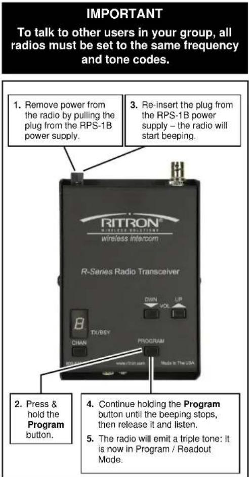
- Place the radio into Program / Readout Mode by following the instructions in Figure-2 at right. A "P" will appear on the LED display as you enter program mode.
- Release the Program button after the beeping has stopped. The radio will display a series of six characters for Radio Identification, with each character separated by a hyphen. The 1st two characters indicate the model number, the 3rd and 4th characters indicate the radio type, and the 5th and 6th characters indicate the firmware revision.
In this example: Model: 03
Radio Type: 37
Firmware Revision: 04
the Radio Identification has been displayed the digit 1 will appear, followed by a hyphen, and the radio will emit a triple beep indicating that the radio is in Program / Readout Mode and channel 1 is selected.
the Channel Selector button to select the channel to be read out. The channel number will show briefly on the channel display as you step through the channels. When you have settled on a channel the display will show a hyphen to indicate that it is ready for readout. - Press and release the On/Volume Up button. The radio will begin to display a series of digits; with each digit separated by a hyphen.
- Radio will first display Program Code "F", followed by the 2 or 3-digit frequency code (see Table 1). The channel is PC-programmed for any frequency not listed in Table 1, an error tone will sound and an "E" will appear on the display.
- The radio will next display Program Code "b", followed by a 2-digit tone code or 3-digit DQC code. See Table 2 for tone codes or Table 3 for DQC codes.
- If the radio has been programmed for DTMF or Selcall encode, Program Code "C" will be displayed, followed by "1" for DTMF or "2" for Selcall, and then the encode programming. ENCODE CODE
- Repeat Steps 4-8 to readout additional channels. Once you have completed channel readout, remove the RPS-1B power supply plug to turn the radio off. Re-insert the RPS-1B power supply plug for normal operation.


text_image
IMPORTANT To talk to other users in your group, all radios must be set to the same frequency and tone codes. 1. Remove power from the radio by pulling the plug from the RPS-1B power supply. 2. Press & hold the Program button. 3. Re-insert the plug from the RPS-1B power supply – the radio will start beeping. 4. Continue holding the Program button until the beeping stops, then release it and listen. 5. The radio will emit a triple tone: It is now in Program / Readout Mode.Figure-2: HOW TO PLACE THE RADIO IN PROGRAM / READOUT MODE
HOW TO FIELD PROGRAM FREQUENCY & TONE CODES
To match other radios, the owner can select Frequency, Tone and DQC Codes from Table 1, Table 2 and Table 3. In our example, channel 3 of a UHF DoorCom ^™ is programmed to operate on the "Brown Dot" frequency of 464.500 MHz with 100.0 Hz tone.
| 22 | 1. Refer to Table 1 to determine the 2 or 3-digit frequency code and write it down. |
| 12 | 2. Refer to Table 2 to determine the 2-digit tone code for 100.0 Hz and write it down. |
| 3. Place the radio into Program / Readout Mode by following the instructions in Figure-2. A "P" will appear on the LED display as you enter program mode. If the radio is already in Program / Readout Mode proceed with programming starting at Step 6. | |
| 4. Release the Program button after the beeping has stopped. The radio will display a series of six characters for Radio Identification, with each character separated by a hyphen. The 1st two characters indicate the model number, the 3rd and 4th characters indicate the radio type, and the 5th and 6th characters indicate the firmware revision.In this example: Model: 03Radio Type: 37Firmware Revision: 04 | |
| 5. After the Radio Identification has been displayed the digit 1 will appear, followed by a hyphen, and the radio will emit a triple beep indicating that the radio is in program mode and channel 1 is selected. | |
| 6. Press the Channel Selector button to select the channel to be programmed. The channel number will show briefly on the channel display as you step through the channels. When you have settled on a channel the display will show a hyphen to indicate that it is ready for programming. | |
| 7. Click the Program button until the program display shows the Program Code "F". Pause—the radio will sound a low tone and show a hyphen across the center of the display to indicate that it is ready to accept the 2 or 3-digit Frequency code from Table 1. | |
| 8. First the 1 | ^st digit of the frequency code by clicking the Program button until the program display shows the desired number. Pause—the radio will sound a low tone and show a hyphen across the center of the display to indicate that it is ready to accept the next digit. |
| 9. Second the 2 | ^nd digit of the frequency code by clicking the Program button until the program display shows the desired number. Pause—the radio sounds a low tone and will show a hyphen across the center of the display to indicate that it is ready to accept the next digit. |
| 10. If necessary, enter the 3 | ^rd digit of the frequency code by clicking the Program button until the program display shows the desired number. Pause—the radio sounds a low tone and will show a hyphen across the center of the display to indicate that it is ready to accept the next digit |
| 11. Press and release the ON/VOLUME UP button to save your programming. A triple beep will sound to indicate that programming was successful and a hyphen will appear on the program display. The radio is now ready for another program entry.NOTE: An error tone will sound if you attempt to save an incorrect code, an "E" will appear on the display. Check the digits you are attempting to enter, then re-enter. This will also occur if the radio frequency has been PC programmed to something other than one of the table codes from Table 1. | |
| 12. Click the Program button until the program display shows the Program Code "b". Pause—the radio will sound a low tone and show a hyphen across the center of the display to indicate that it is ready to accept the 2-digit Quiet-Call code or 3-digit Digital Quiet-Call code from Table 2 or Table 3. | |
| 13. Enter the 1 | ^st digit of the tone code (or 1^st digit of the DQC code) by clicking the Program button until the program display shows the desired number. Pause—the radio sounds a low tone and will show a hyphen across the center of the display to indicate that it is ready to accept the next digit. |
| 14. Enter the 2 | ^nd digit of the tone code (or 2^nd digit of the DQC code) by clicking the Program button until the program display shows the desired number. Pause—the radio sounds a low tone and will show a hyphen across the center of the display to indicate that it is ready to accept the next digit. |
| 15. FOR DQC CODES ONLY – Enter the 3^rd digit of the DQC code by clicking the Program button until the program display shows the desired number. Pause—the radio sounds a low tone and will show a hyphen across the center of the display to indicate that it is ready to accept the next digit. | |
| 16. Press and release the ON/VOLUME UP button to save your programming. A triple beep will sound to indicate that programming was successful and a hyphen will appear on the program display. The radio is now ready for another program entry.NOTE: An error tone will sound if you attempt to save an incorrect code, an "E" will appear on the display. Check the digits you are attempting to enter, then re-enter. | |
| 17. Repeat Steps 6-16 to program additional channels. Once you have made your final program entry, remove the RPS-1B power supply plug to turn the radio off. Re-insert the RPS-1B power supply plug for normal operation. |
TABLE 1: PROGRAMMABLE FREQUENCY CODES
| UHF Business Band Models | |||
| Code | Frequency | Color Dot | BW |
| 09 | 469.2625 | 12.5 † | |
| 10 | 462.5750 | White Dot | 12.5 † |
| 11 | 462.6250 | Black Dot | 12.5 † |
| 12 | 462.6750 | Orange Dot | 12.5 † |
| 13 | 464.3250 | 12.5 † | |
| 14 | 464.8250 | 12.5 † | |
| 15 | 469.5000 | 12.5 † | |
| 16 | 469.5500 | 12.5 † | |
| 17 | 463.2625 | 12.5 † | |
| 18 | 464.9125 | 12.5 † | |
| 19 | 464.6000 | 12.5 † | |
| 20 | 464.7000 | 12.5 † | |
| 21 | 462.7250 | 12.5 † | |
| 22 | 464.5000 | Brown Dot | 12.5 |
| 23 | 464.5500 | Yellow Dot | 12.5 |
| 24 | 467.7625 | J 12.5 | |
| 25 | 467.8125 | K | 12.5 |
| 26 | 467.8500 | Silver Star | 12.5 |
| 27 | 467.8750 | Gold Star | 12.5 |
| 28 | 467.9000 | Red Star | 12.5 |
| 29 | 467.9250 | Blue Star | 12.5 |
| 30 | 461.0375 | 12.5 | |
| 31 | 461.0625 | 12.5 | |
| 32 | 461.0875 | 12.5 | |
| 33 | 461.1125 | 12.5 | |
| 34 | 461.1375 | 12.5 | |
| 35 | 461.1625 | 12.5 | |
| 36 | 461.1875 | 12.5 | |
| 37 | 461.2125 | 12.5 | |
| 38 | 461.2375 | 12.5 | |
| 39 | 461.2625 | 12.5 | |
| 40 | 461.2875 | 12.5 | |
| 41 | 461.3125 | 12.5 | |
| 42 | 461.3375 | 12.5 | |
| 43 | 461.3625 | 12.5 | |
| 44 | 462.7625 | 12.5 | |
| 45 | 462.7875 | 12.5 | |
| 46 | 462.8125 | 12.5 | |
| 47 | 462.8375 | 12.5 | |
| 48 | 462.8625 | 12.5 | |
| 49 | 462.8875 | 12.5 | |
| 50 | 462.9125 | 12.5 | |
| 51 | 464.4875 | 12.5 | |
| 52 | 464.5125 | 12.5 | |
| 53 | 464.5375 | 12.5 | |
| 54 | 464.5625 | 12.5 | |
| 55 | 466.0375 | 12.5 | |
| 56 | 466.0625 | 12.5 | |
| 57 | 466.0875 | 12.5 | |
| 58 | 466.1125 | 12.5 | |
| 59 | 466.1375 | 12.5 | |
| 60 | 466.1625 | 12.5 | |
| 61 | 466.1875 | 12.5 | |
| 62 | 466.2125 | 12.5 | |
| 63 | 466.2375 | 12.5 | |
| 64 | 466.2625 | 12.5 | |
| 65 | 466.2875 | 12.5 | |
| 66 | 466.3125 | 12.5 | |
| UHF Business Band Models | |||
| Code | Frequency | Color Dot | BW |
| 67 | 466.3375 | 12.5 | |
| 68 | 466.3625 | 12.5 | |
| 69 | 467.7875 | 12.5 | |
| 70 | 467.8375 | 12.5 | |
| 71 | 467.8625 | 12.5 | |
| 72 | 467.8875 | 12.5 | |
| 73 | 467.9125 | 12.5 | |
| 74 | 469.4875 | 12.5 | |
| 75 | 469.5125 | 12.5 | |
| 76 | 469.5375 | 12.5 | |
| 77 | 469.5625 | 12.5 | |
| 78 | 462.1875 | 12.5 | |
| 79 | 462.4625 | 12.5 | |
| 80 | 462.4875 | 12.5 | |
| 81 | 462.5125 | 12.5 | |
| 82 | 467.1875 | 12.5 | |
| 83 | 467.4625 | 12.5 | |
| 84 | 467.4875 | 12.5 | |
| 85 | 467.5125 | 12.5 | |
| 86 | 451.1875 | 12.5 | |
| 87 | 451.2375 | 12.5 | |
| 88 | 451.2875 | 12.5 | |
| 89 | 451.3375 | 12.5 | |
| 90 | 451.4375 | 12.5 | |
| 91 | 451.5375 | 12.5 | |
| 92 | 451.6375 | 12.5 | |
| 93 | 452.3125 | 12.5 | |
| 94 | 452.5375 | 12.5 | |
| 95 | 452.4125 | 12.5 | |
| 96 | 452.5125 | 12.5 | |
| 97 | 452.7625 | 12.5 | |
| 98 | 452.8625 | 12.5 | |
| 99 | 456.1875 | 12.5 | |
| 100 | 456.2375 | 12.5 | |
| 101 | 456.2875 | 12.5 | |
| 102 | 468.2125 | 12.5 | |
| 103 | 468.2625 | 12.5 | |
| 104 | 468.3125 | 12.5 | |
| 105 | 468.3625 | 12.5 | |
| 106 | 468.4125 | 12.5 | |
| 107 | 468.4625 | 12.5 | |
| 108 | 468.5125 | 12.5 | |
| 109 | 468.5625 | 12.5 | |
| 110 | 468.6125 | 12.5 | |
| 111 | 468.6625 | 12.5 | |
| 112 | 456.3375 | 12.5 | |
| 113 | 456.4375 | 12.5 | |
| 114 | 456.5375 | 12.5 | |
| 115 | 456.6375 | 12.5 | |
| 116 | 457.3125 | 12.5 | |
| 117 | 457.4125 | 12.5 | |
| 118 | 457.5125 | 12.5 | |
| 119 | 457.7625 | 12.5 | |
| 120 | 457.8625 | 12.5 | |
| 121 | 461.3175 | 12.5 | |
| 122 | 464.8375 | 12.5 | |
| 00 Delete Code * | |||
| VHF Business Band Models | |||
| Code | Frequency | Color | Dot BW |
| 03 | 151.6250 | Red Dot | 12.5 † |
| 04 | 151.9550 | Purple Dot | 12.5 † |
| 05 | 151.9250 | 12.5 † | |
| 06 | 154.5400 | 12.5 † | |
| 07 | 154.5150 | 12.5 † | |
| 08 | 154.6550 | 12.5 † | |
| 09 | 151.6850 | 12.5 † | |
| 10 | 151.7150 | 12.5 † | |
| 11 | 151.7750 | 12.5 † | |
| 12 | 151.8050 | 12.5 † | |
| 13 | 151.8350 | 12.5 † | |
| 14 | 151.8950 | 12.5 † | |
| 15 | 154.4900 | 12.5 † | |
| 16 | 151.6550 | 12.5 † | |
| 17 | 151.7450 | 12.5 † | |
| 18 | 151.8650 | 12.5 † | |
| 24 | 151.7000 | 12.5 | |
| 25 | 151.7600 | 12.5 | |
| 26 | 152.7000 | 12.5 † | |
| 27 | 152.8850 | 12.5 | |
| 28 | 152.9150 | 12.5 | |
| 29 | 152.9450 | 12.5 | |
| 30 | 151.5125 | 12.5 | |
| 31 | 154.5275 | 12.5 | |
| 32 | 153.0050 | 12.5 | |
| 33 | 158.4000 | 12.5 | |
| 34 | 158.4075 | 12.5 | |
| 00 Delete Code* | |||
| VHF MURS Models** | |||
| Code | Frequency | Color Dot | BW |
| 01 | 154.600 | Green Dot | 25.0 |
| 02 | 154.570 | Blue Dot | 25.0 |
| 19 | 151.820 | MURS | 12.5 |
| 20 | 151.880 | MURS | 12.5 |
| 21 | 151.940 | MURS | 12.5 |
| 22 | 154.600 | MURS | 12.5 |
| 23 | 154.570 | MURS | 12.5 |
| 00 Delete Code* | |||
| Notes |
| * Code 00 will delete the channel, it will not be available with the channel button. |
| ** MURS models do not require an FCC license. All other models require an FCC license. |
| † Frequency code was 25 kHz BW prior to the 2013 FCC Narrowband Mandate. |
| • BW is the bandwidth in kHz. |
| • 12.5 kHz indicates narrow band channel, 25 kHz indicates wide band channel. |
| • If the radio has been PC programmed to a non-table frequencies it cannot be changed via field programming. Code 999 will appear when read out. |
CANADIAN FREQUENCY CODES
| Canada ModelsUHF Business Band | ||
| Code | Frequency | Color Dot BW |
| 01 | 458.6625 | 25 |
| 02 | 469.2625 | 25 |
| Canada ModelsVHF Business Band | ||
| Code | Frequency | Color Dot BW |
| 01 | 151.055 | 25 |
| 02 | 151.115 | 25 |
TABLE 2: PROGRAMMABLE QC TONE CODES
| Code | Frequency |
| 01 | 67.0 |
| 02 | 71.9 |
| 03 | 74.4 |
| 04 | 77.0 |
| 05 | 79.7 |
| 06 | 82.5 |
| 07 | 85.4 |
| 08 | 88.5 |
| 09 | 91.5 |
| 10 | 94.8 |
| 11 | 97.4 |
| 12 | 100.0 |
| 13 | 103.5 |
| Code | Frequency |
| 14 | 107.2 |
| 15 | 110.9 |
| 16 | 114.8 |
| 17 | 118.8 |
| 18 | 123.0 |
| 19 | 127.3 |
| 20 | 131.8 |
| 21 | 136.5 |
| 22 | 141.3 |
| 23 | 146.2 |
| 24 | 151.4 |
| 25 | 156.7 |
| 26 | 162.2 |
| Code | Frequency |
| 27 | 167.9 |
| 28 | 173.8 |
| 29 | 179.9 |
| 30 | 186.2 |
| 31 | 192.8 |
| 32 | 203.5 |
| 33 | 210.7 |
| 34 | 218.1 |
| 35 | 225.7 |
| 36 | 233.6 |
| 37 | 241.8 |
| 38 | 250.3 |
| 39 | 69.4 |
| Code | Frequency |
| 40 | 159.8 |
| 41 | 165.5 |
| 42 | 171.3 |
| 43 | 177.3 |
| 44 | No Tone |
| 45 | 183.5 |
| 46 | 189.9 |
| 47 | 196.6 |
| 48 | 199.5 |
| 49 | 206.5 |
| 50 | 229.1 |
| 51 | 254.1 |
| 00 | No Tone |
For special applications the R-Series DoorCom ^™ can be programmed to transmit a DTMF or Selcall code on each transmission. The user is able to field program the radio for any 3-7 digit DTMF or Selcall sequence. In our example we will program channel 3 of a UHF DOORCOM ^™ radio to operate with a DTMF ANI string of 1234.
1234ite down the desired DTMF or Selcall ANI code.

- Place the radio into Program / Readout Mode by following the instructions in Figure-2. A "P" will appear on the LED display as you enter program mode. If the radio is already in Program / Readout Mode proceed with programming starting at Step 5.

- Release the Program button after the beeping has stopped. The radio will display a series of six characters for Radio Identification, with each character separated by a hyphen. The 1st two characters indicate the model number, the 3rd and 4th characters indicate the radio type, and the 5th and 6th characters indicate the firmware revision.
ble: Model: 03
37
Firmware Revision: 04

- After the Radio Identification has been displayed the digit 1 will appear, followed by a hyphen, and the radio will emit a triple beep indicating that the radio is in program mode and channel 1 is selected.

- Press the Channel Selector button to select the channel to be programmed. The channel number will show briefly on the channel display as you step through the channels. When you have settled on a channel the display will show a hyphen to indicate that it is ready for programming.

- Click the Program button until the program display shows the Program Code "C". Pause—the radio will sound a low tone and show a hyphen across the center of the display to indicate that it is ready to accept a 3 to 7-digit DTMF or Selcall decode sequence.

- TO REMOVE DTMF OR SELCALL PROGRAMMING – Enter a "0" using the Program button. Pause—the radio will sound a low tone and show a hyphen across the center of the display to indicate that it is ready to accept the next digit. Proceed to Step 11 to save this programming change.

- FOR DTMF CODES ONLY – Enter a "1" using the Program button. Pause—the radio will sound a low tone and show a hyphen across the center of the display to indicate that it is ready to accept the next digit.

- FOR SELCALL CODES ONLY – Enter a "2" using the Program button. Pause—the radio will sound a low tone and show a hyphen across the center of the display to indicate that it is ready to accept the next digit.
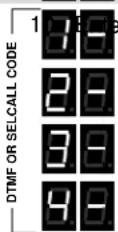
^st digit of the DTMF or Selcall code by clicking the Program button until the program display shows the desired number. Pause—the radio will sound a low tone and show a hyphen across the center of the display to indicate that it is ready to accept the next digit. Continue entering up to seven digits.

- Press and release the ON/VOLUME UP button to save your programming. A triple beep will sound to indicate that programming was successful and a hyphen will appear on the program display. The radio is now ready for another program entry.

NOTE: An error tone will sound if you attempt to save an incorrect code, an "E" will appear on the display. Check the digits you are attempting to enter, then re-enter.
- Repeat Steps 5-11 to program additional channels. Once you have made your final program entry, remove the RPS-1B power supply plug to turn the radio off. Re-insert the RPS-1B power supply plug for normal operation.
HOW TO FIELD PROGRAM ADVANCED FEATURE CODES
The R-Series DoorCom ^™ can be field programmed for a number of advanced features. Refer to Table 4 for the two or three digit codes available for field programming. In our example we will program the radio a Turn-On Volume level of “5”.
| 25 | 1. Refer to Table 4 to determine the two or three-digit Advanced Features code and write it down. |
| 2. Place the radio into Program / Readout Mode by following the instructions in Figure-2. A “P” will appear on the LED display as you enter program mode. If the radio is already in Program / Readout Mode proceed with programming starting at Step 5. | |
| 3. Release the Program button after the beeping has stopped. The radio will display a series of six characters for Radio Identification, with each character separated by a hyphen. The 1st two characters indicate the model number, the 3rd and 4th characters indicate the radio type, and the 5th and 6th characters indicate the firmware revision. | |
| 4. After the Radio Identification has been displayed the digit 1 will appear, followed by a hyphen, and the radio will emit a triple beep indicating that the radio is in program mode and channel 1 is selected. | |
| 5. Press the Channel Selector button to select the channel to be programmed. The channel number will show briefly on the channel display as you step through the channels. When you have settled on a channel the display will show a hyphen to indicate that it is ready for programming. If the Advanced Feature code to be programmed is radio wide this step can be skipped. | |
| 6. Click the Program button until the program display shows the Program Code “A”. Pause—the radio will sound a low tone and show a hyphen across the center of the display to indicate that it is ready to accept a 2-digit or a 3-digit Feature code. | |
| 7. Enter the 1 | ^st digit of the feature code by clicking the Program button until the program display shows the desired number. Pause—the radio will sound a low tone and show a hyphen across the center of the display to indicate that it is ready to accept the next digit. |
| 8. Enter the 2 | ^nd digit of the feature code (if necessary) by clicking the Program button until the program display shows the desired number. Pause—the radio sounds a low tone and will show a hyphen across the center of the display to indicate that it is ready to accept the next digit. |
| 9. Enter the 3 | ^rd digit of the feature code (if necessary) by clicking the Program button until the program display shows the desired number. Pause—the radio sounds a low tone and will show a hyphen across the center of the display to indicate that it is ready to accept the next digit. |
| 10. Press and release the ON/VOLUME UP button to save your programming. A triple beep will sound to indicate that programming was successful and a hyphen will appear on the program display. The radio is now ready for another program entry. | |
| NOTE: An error tone will sound if you attempt to save an incorrect code, an "E" will appear on the display. Check the digits you are attempting to enter, then re-enter. | |
| 11. Repeat Steps 5-10 to program additional Advanced Features. Once you have made your final program entry, remove the RPS-1B power supply plug to turn the radio off. Re-insert the RPS-1B power supply plug for normal operation. |
TABLE 4: ADVANCED FEATURE CODES
| Code Feature Key Description | ||
| Radio Wide Features | ||
| 2x Turn On Volume Radio turns on to volume level x. (x = 0-9) | ||
| 70 Turn On to Channel 1 Disabled √ When radio is turned on it will go to last channel used. | ||
| 71 Turn On to Channel 1 Enabled When radio is turned on it will go to Channel 1. | ||
| 91 Call Tone Low √ Call Tone will be transmitted at a low level. | ||
| 92 Call Tone High Call Tone will be transmitted at a high level. | ||
| Per Channel Features | ||
| 110 High Power √ | ||
| 111 Low Power | ||
| 120 Busy Channel TX Inhibit Disable √ | ||
| 121 Busy Channel TX Inhibit Enable Prevents TX if a signal is present on the receiver. | ||
| 130 RX Beep Disable √ | ||
| 131 RX Beep Enable Beep at the end of a received message. | ||
| 140 TX Beep Disable | ||
| 141 TX Beep Enable √ Beep when radio is ready for user to talk. | ||
| Programming Readout Codes | ||
| 81 Frequency Code Display will sequentially show the programmed 2 or 3-digit Frequency Code. (1) | ||
| 82 QC or DQC Tone Code Display will sequentially show the programmed 2-digit QC Tone Code or 3-digit DQC Tone Code. (2) | ||
| 83 2-Tone, DTMF or Selcall Encode Code DTMF Display will sequentially show the programmed 2-digit 2-Tone Code, or the 3 to 7-digit or Selcall Code | ||
| 89 Reset to Factory Defaults Resets the R-Series DoorComTM to Factory default programming. Channel 1 and 2 are reset to factory default, channels 3-10 are deleted. |
KEY: √ The R-Series DoorCom™ is set from the factory with these options enabled.
NOTES: (1) 999 indicates a non-table frequency or that TX and RX are not the same
(2) If the RX and TX tone codes are not the same, or if DCS is inverted you will get an ERROR indication
(4) ERROR indication will be displayed if not a Field Programming value (has been PC programmed)
HOW TO FIELD PROGRAM DOORCOM™ CODES
The R-Series DoorCom ^™ can be field programmed for a number of DoorCom ^™ specific features. Refer to Table 5 for the two digit codes available for field programming. In our example we will program the radio for a “Door Bell” type calltone.
| 31 | 1. Refer to Table 5 to determine the two-digit DoorComTM code and write it down. |
| 2. Place the radio into Program / Readout Mode by following the instructions in Figure-2. A "P" will appear on the LED display as you enter program mode. If the radio is already in Program / Readout Mode proceed with programming starting at Step 5. | |
| 3. Release the Program button after the beeping has stopped. The radio will display a series of six characters for Radio Identification, with each character separated by a hyphen. The 1st two characters indicate the model number, the 3rd and 4th characters indicate the radio type, and the 5th and 6th characters indicate the firmware revision. | |
| 4. After the Radio Identification has been displayed the digit 1 will appear, followed by a hyphen, and the radio will emit a triple beep indicating that the radio is in program mode and channel 1 is selected. | |
| 5. Click the Program button until the program display shows the Program Code "r". Pause—the radio will sound a low tone and show a hyphen across the center of the display to indicate that it is ready to accept a 2-digit DoorComTM code. | |
| ^st digit of the DoorComTM code by clicking the Program button until the program display shows the desired number. Pause—the radio will sound a low tone and show a hyphen across the center of the display to indicate that it is ready to accept the next digit. | |
| ^nd digit of the DoorComTM code by clicking the Program button until the program display shows the desired number. Pause—the radio sounds a low tone and will show a hyphen across the center of the display to indicate that it is ready to accept the next digit. | |
| 9. Press and release the ON/VOLUME UP button to save your programming. A triple beep will sound to indicate that programming was successful and a hyphen will appear on the program display. The radio is now ready for another program entry. | |
| NOTE: An error tone will sound if you attempt to save an incorrect code, an "E" will appear on the display. Check the digits you are attempting to enter, then re-enter. | |
| 10. Repeat Steps 5-9 to program additional DoorComTM codes. Once you have made your final program entry, remove the RPS-1B power supply plug to turn the radio off. Re-insert the RPS-1B power supply plug for normal operation. |
TABLE 5: DOORCOM™ CODES
| Code | Feature | Key | Description |
| 11 | Disable Manager Lockout | √ | Disables Manager Lockout operation. |
| 12 | Enable Manage Lockout | Enables Manager Lockout, allowing radio controls to be “Locked”. The operating channel and speaker volume settings cannot be changed. | |
| 21 | Enable Call Tone | √ | Enables a Call Tone that is transmitted and is heard on the speaker. |
| 22 | Disable Call Tone | Disables a Call Tone that is transmitted and is heard on the speaker. | |
| 31 | Call Tone – Doorbell | √ | Sets the Call Tone to sound like a doorbell. |
| 32 | Call Tone – Ring Tone | Sets the Call Tone to sound like a ringing signal. | |
| 41 | Disable Transmit Timeout Tone | Disables a transmitted Timeout Tone when the Automatic Turnoff Reset Time has expired. | |
| 42 | Enable Transmit Timeout Tone | √ | Enables a transmitted Timeout Tone when the Automatic Turnoff Reset Time has expired. |
| 51 | Disable Auto Turn Off mode | Intercom mode where you always hears all radio activity on the speaker. | |
| 52 | Enable Auto Turn Off mode | √ | Auto Turn Off mode where the radio mutes after the Auto Turn Off Time has expired. |
| DoorComTM Auto Turn Off Mode Inactivity Reset Time | |||
| 61 | 5 seconds | Inactivity Reset Time is th length of time the radio can remain inactive (not receiving or transmitting) before the audio is muted. Once muted, no signal will be received until the Push-to-Talk button has first been pressed. | |
| 62 | 10 seconds | √ | |
| 63 | 20 seconds | ||
| 64 | 30 seconds | ||
| 65 | 45 seconds | ||
| 66 | 1 minute | ||
| 67 | 2 minutes | ||
| 68 | 3 minutes | ||
| 69 | 4 minutes | ||
KEY: √ The R-Series DoorCom™ is set from the factory with these options enabled.
RDC-1 SPEAKER INTERCOM BOX INSTALLATION INSTRUCTIONS
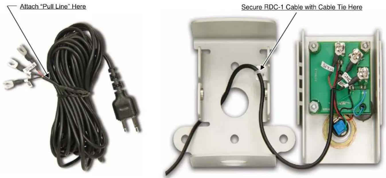
If you intend to mount the metal RDC-1 speaker intercom box on an outside wall, it will be necessary to route the special connecting cable through a hole in the exterior wall.
To make the routing process easier and the required hole smaller, we suggest routing the end of the cable that contains the 3 spade lugs. You will need to spearate the front of the RDC-1 from the back and disconnect the three spade lugs from the screw terminals.
When ready to pass the cable through the hole, attach a "pull line" BELOW the crimp attachment point of the spade lugs and gently pull the cable through the hole (refer to Figure-3).
The RDC-1 Speaker Intercom Box can be secured to virtually any surface (INDOOR/OUTDOOR) using up to four (4) screws (not included).
Installation of RDC-1: (Refer to Figure-3)
- Determine the method of securing the RDC-1.
a. Use the holes in the mounting tabs on the sides of the RDC-1.
b. OR Use the mounting holes located directly on the back of the RDC-1.
- Determine the routing of the RDC-1 Cable.
a. Through the back of the RDC-1.
b. OR Through the bottom of the RDC-1.
-
Choose a size, type of screw thread and screw length which will hold firmly in the surface to which the unit will be mounted.
-
If required, drill the (2) holes to secure the RDC-1 into the wall mounting surface.
-
If required, drill the hole to route the RDC-1 Cable through the mounting surface. The hole must be large enough to pass the cable end containing the (3) spade lugs. We suggest a 0.5"(1/2")minimum diameter size hole.
-
Route the RDC-1 Cable through the drilled hole.
-
Using the included Torx bit, remove the (2) T-25 TORX screws securing the front and rear panels of the RDC-1.
-
Secure the rear panel of the RDC-1 to the mounting surface using the (2) screws selected in Step 3.
-
If routing RDC-1 Cable through the bottom of the rear panel, remove the conduit plug, install the require length of conduit, and route the RDC-1 Cable through the conduit into the RDC-1 box.
-
CAREFULLY re-connect the (3) spade lugs of the RDC-1 Cable to the (3) correct screw terminals located on the inside of the front panel.
Take care to match the name on the spade lug label to the same name printed near the screw terminal (refer to Figure-3).
-
Secure the RDC-1 Cable to the RDC-1 rear panel tab using the small cable tie (refer to Figure-3).
-
Place the RDC-1 front panel over the rear panel and secure with the (2) T-25 TORX screws.
-
You may want to consider routing the connecting cable through conduit and attaching the conduit to the RDC-1 (back or bottom hole). The hole size in the RDC-1 is 0.875"(7/8").
text_image
Attach "Pull Line" Here Secure RDC-1 Cable with Cable Tie HereFigure-3: RDC-1 Installation
R-SERIES RADIO INSTALLATION INSTRUCTIONS
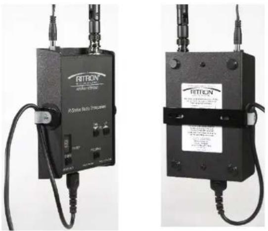
The R-Series Radio can be placed INDOORS only, on any flat surface or secured to virtually any surface with the JBS-MMK Mounting Kit using only two (2) screws(not included). Observe CAUTIONS listed below when mounting.
Installation of the R-Series radio: (Refer to Figure-4)
If required, the RDC-1 Cable was routed in the previous instructions. The RDC-1 Cable end with the 2.5mm/3.5mm plug should be available for installation.
Determine the location for the R-Series radio. The length of the RDC-1 Cable is 20', the R-Series radio must be located within that distance from the RDC-1. The R-Series radio also requires 110VAC (see included RPS-1B power supply) or external 12VDC power supply within close proximity.
If using the JBS-MMK Mounting Kit, use the following instructions.
- Choose a size, type of screw thread and screw length which will hold firmly in the surface to which the unit will be mounted.
- If required, drill the (2) holes to secure the mounting bracket to the mounting surface.
- Secure the mounting bracket to the mounting surface with the screws selected in Step 1.
- Using the (2) screws, (2) rubber washers, nylon cable clamp, and (2) small cable ties provided in the mounting kit, secure the R-Series radio to the mounting bracket as shown in Figure-4.
- Attach AFB-1545 antenna to the antenna connector and place antenna in the VERTICAL position. If greater coverage is required, use the remote mount Ritron remote mount magnetic mount antenna RAM-1545.
- Plug the RPS-1B power supply into the 110VAC wall socket, and plug the other end into the DC Power Connector located on the top of the R-Series radio. The radio will automatically power-up.
- Plug the 2.5/3.5mm plug of the connecting cable attached to the RDC-1 into the 2.5/3.5mm jack on the bottom of the R-Series Transceiver.
- If required, program the radio. Refer to the programming section of this manual for details.
- Select the correct channel with the Channel Button and set the correct audio level with the Volume Buttons.
The R-Series Transceiver can be powered as follows:
• (INDOOR USE ONLY) Use only the included RPS-1B 110VAC AC adapter to power the radio transceiver.
CAUTIONS
- Antenna MUST be connected to radio BEFORE transmitting.
- Position antenna in VERTICAL position.
- Keep antenna AWAY from all metal objects and power lines. Maintain at least 3ft of clearance on all sides.
- DO NOT route AC cord along-side or near the antenna.
- Route power and AC Cord AWAY from Radio.
•
natural_image
Two black electronic device units with attached cables, one labeled 'A-Strive Bus Protocol' and the other 'FETRON' (no visible text or symbols on the devices themselves)Figure-4: R-Series Radio Installation
INITIATING A CALL (Default is Automatic Turn-Off)
- Press and HOLD the PTT button to talk.
A unique Call Tone will be sent to radio-equipped personnel when the PTT button is pressed. The Call Tone is also heard on the speaker at the RDC-1. - Begin speaking after the beep.
The caller should be 3 feet or less from the microphone. - Release PTT button to listen.
RECEIVING A CALL
- Any return call from a radio will then be heard on the RDC-1 speaker.
NOTES:
- If a return call is not received within 10 seconds of releasing the PTT button AND, there is no additional radio activity on the channel (the Inactivity Rest Time Default is 10 seconds), the speaker on the RDC-1 will sound a hi/low double-tone and then the speaker will turn off automatically.
- If ENABLED (DoorCom ^TM Time-Out Tone), the same distinct tones will be transmitted to radio-equipped personnel to signal that the speaker has turned off and internal communications can continue.
- No calls from radio-equipped personnel will be heard on the RDC-1 speaker. Pressing the PTT button on the RDC-1 again will turn the speaker on and will resend the Call Tone.
The Automatic Turn-Off feature is designed to prevent eavesdropping at the RDC-1 speaker.
System Range and Coverage
The typical range of the DoorCom ^™ system is defined as: 1 floor, 350,000sq. ft.. Coverage depends on building structure and/or surrounding typography. Concrete walls, steel, metal shelving, racks, etc. can further reduce your coverage.
Site Survey: Before permanently installing the DoorCom ^™ system, we recommend that you conduct a site survey to determine the actual radio coverage in your facility.
- You will need two people to conduct the site survey: One person to operate the DoorCom™ system, the other person to walk the facility with a compatible portable 2-way radio.
- Temporarily position the DoorCom ^™ system in or near the location it will be mounted. Note: Locating the radio transceiver with antenna as close as possible to the desired mounting location is critical to an accurate site survey.
- Apply power to the DoorCom ^™ system and initiate a call to the other 2-way radio. Continue the conversation while the person with the portable radio moves to a variety of locations in the facility.
- If you are unable to achieve the desired coverage:
A. Try mounting the radio with the included antenna slightly higher. Keep in mind the included connecting cable that connects the radio to the external speaker intercom box is only 20ft in length.
B. If this is not successful, we offer the optional RAM-1545 magnetic mount antenna with a 25ft cable. This will allow you to locate the antenna separately from the radio.
RADIO ALERT TONES
The radio responds to certain instructions by sounding a beep or series of tones. These tones can tell you that the radio is working as you expect.
Power on/Self Check "OK"
When power is applied to the radio, the radio will run a quick "self test" to confirm basic functions. When complete the radio will sound the Channel Beep and the Channel Display will show the operating channel. The radio is now ready for use.
Transmit Time-Out Timer – (Default is 60 seconds)
If the PTT is pressed longer than the programmed Transmit Time Out Timer time period, a low-tone followed by a higher-pitched tone sounds and the transmitter automatically shuts off.
Call Tone, DTMF or Selcall Sidetone
If the radio is programmed to transmit a Call Tone, DTMF ANI or Selcall ANI the tones will be heard on the radio RDC-1 speaker.
OPTIONAL PROGRAMMABLE RADIO ALERT TONES
DoorCom™ Time-Out Tone – Default is Enabled (PC or Field Programmable)
If ENABLED, a distinct hi/low double-tone will be heard on the speaker of the receiving portable radios. This tone alerts radio-equipped staff that the DoorCom™ speaker has turned OFF and internal communication can now continue.
Courtesy Beep – Default is Not Enabled (PC or Field Programmable)
At the end of each received transmission, a short tone will sound only on the RDC-1 speaker. This indicates that the channel is clear and you may now transmit.
Busy Channel TX Inhibit – Default is Not Enabled (PC or Field Programmable)
When the PTT is pressed and another radio is simultaneously transmitting on your radio frequency without your tone, the radio will beep a series of long, low tones (like a telephone busy signal) and you will not be allowed to transmit.
Transmit Clear To Talk Beep – Default is Not Enabled (PC or Field Programmable)
After the PTT has been pressed a short tone sounds on the RDC-1 speaker. This indicates that the radio is ready for you to begin talking.
EXPOSURE TO RADIO FREQUENCY ENERGY
These products generate radio frequency (RF) energy when the PTT button on the front of the unit is depressed. The product has been evaluated for compliance with the maximum permissible exposure limits for RF energy at the maximum power rating of the unit when using antennas available from RITRON. Antennas other than those mentioned below have not been tested for compliance and may or may not meet the exposure limits at the distances given. Higher gain antennas are capable of generating higher fields in the strongest part of their field and would, therefore, require a greater separation from the antenna.
R-147, R-147M, R-147-CANADA: Using the AFB-1545 antenna included with the product at the 20 cm (7.9 inches) minimum expected separation distance and greater, the maximum RF exposure is well below the General Population/Uncontrolled limits. Antennas other than those available from RITRON have not been tested for compliance and may or may not meet the exposure limits at the distances given. Higher gain antennas are capable of generating higher fields in the strongest part of their field and would, therefore, require a greater separation from the antenna. This product is not to be used by the general public in an uncontrolled environment unless compliance with the Uncontrolled/General Population limits for RF exposure can be assured.
R-447, R-447-CANADA: Using the AFB-1545 antenna included with the product at the 20 cm (7.9 inches) minimum expected separation distance and greater, the maximum RF exposure is well below the General Population/Uncontrolled limits. Antennas other than those available from RITRON have not been tested for compliance and may or may not meet the exposure limits at the distances given. Higher gain antennas are capable of generating higher fields in the strongest part of their field and would, therefore, require a greater separation from the antenna. This product is not to be used by the general public in an uncontrolled environment unless compliance with the Uncontrolled/General Population limits for RF exposure can be assured.
To limit exposure to RF energy to levels below the limit, please observe the following:
- Use only the antenna(s) available from RITRON for these models. DO NOT operate the radio without an antenna.
- DO NOT activate the transmitter when not actually wishing to transmit.
- When transmitting, make certain that the distance limits for the particular model in use are observed.
• DO NOT allow children to operate the radio.
When used as directed, this series of radios is designed to comply with the IC's RF exposure limits for "Uncontrolled/General Population". In addition, they are designed to comply with the following Standards and Guidelines:
- United States Federal Communications Commission, Code of Federal Regulations; 47 CFR §§ 2 sub-part J.
• American National Standards Institute (ANSI) / Institute of Electrical and Electronic Engineers (IEEE) C95. 1-1992. - Institute of Electrical and Electronic Engineers (IEEE) C95.1-1999 Edition.
COPYRIGHT TELECOMMUNICATIONS INDUSTRY ASSOCIATION
2013 FCC NARROWBAND MANDATE
On January 1, 2013, pursuant to the FCC Narrowband mandate, Ritron will no longer be allowed to manufacture wide band (25 kHz) capable radio equipment that operates in the frequency bands from 150 MHz to 512 MHz. All Ritron Base Radios are FCC certified for narrowband operation, so the only change required is the elimination of wideband operation.
To meet the FCC narrowband mandate by Jan 1, 2013, Ritron will initiate the transition process of manufacturing narrowband only compliant radio equipment beginning July 1, 2012. After that date, customer orders will begin to be filled with radios manufactured for FCC narrowband compliance, with no provisions for wideband operation except where allowed by FCC rule. These radios will be clearly marked as “FCC Narrowband Compliant”. The narrowband manufacturing process will proceed gradually on a model by model basis, with all models narrowband compliant by the January 1, 2013 deadline.
For a complete list of Ritron radios capable of narrowband operation; a Ritron FAQ on the subject, and various links on the FCC website dealing with Narrowbanding go to:
www.ritron.com/narrowband
If you have any questions contact us at 1-800-872-1872
OBSERVE CAUTION IN THE FOLLOWING ENVIRONMENTS TO MAXIMIZE THE LIFE OF YOUR RADIO EQUIPMENT
LOCATION: Be aware that this radio and / or antenna may create interference with, or be interfered with, by nearby electronic equipment such as computers, monitors, keyboards, electronic telephones and other sensitive devices. Either move the equipment or use a remote antenna to separate components sufficiently to stop or reduce interference.
MOISTURE: Ritron base radios are not waterproof. DO NOT directly expose them to rain or excessive moisture.
CHEMICALS: Detergents, alcohol, aerosol sprays or petroleum products can damage the radio case. DO NOT use petroleum solvents of any kind; use a soft cloth moistened with water to clean the case.
EXTREME HEAT: High temperatures can damage the radio and its components. DO NOT expose the units to extreme heat or leave them in direct sunlight.
EXCESSIVE TRANSMISSIONS: DO NOT hold the Push-To-Talk switch down longer than necessary during transmission intervals.
VIBRATION / SHOCK: Although your Ritron base radio is designed to be rugged, it will not survive excessive abuse. Avoid dropping the radio.
RDC-Series DoorCom™ Wireless Intercom Licensing
FCC LICENSING
Except for the five (5) MURS frequencies listed on page 7, the FCC requires the owners of radios operating on these frequencies to obtain a station license before using them.
The station licensee is responsible for ensuring that transmitter power, frequency and deviation are within the limits specified by the station license. The station licensee is also responsible for proper operation and maintenance of the radio equipment. This includes checking the transmitter frequency and deviation periodically, using appropriate methods.
To get an FCC license for VHF or UHF frequencies, submit FCC application Form 601. Your Ritron dealer can help you with this process.
HOW TO OBTAIN AN FCC RADIO LICENSE
Because your Ritron radio operates on Private Land Mobile frequencies, it is subject to the Rules and Regulations of the FCC, which requires all operators of these frequencies to obtain a station license before operating their equipment. Make application for your FCC license on FCC Forms 601, Schedules D and H, and Fee Remittance Form 159.
To have forms and instructions faxed to you by the FCC, call the FCC Fax-On-Demand system at 202-418-0177 from your fax machine; request Document numbers 3000159, 3060001, 3060003, and 3060006.
To have Document numbers 3000159, 3060001, 3060003, and 3060006 mailed to you, call the FCC Forms Hotline at 800-418-FORM (800-418-3676).
For help with questions concerning the license application, contact the FCC at 888-CALL-FCC (888-225-5322) or log on at www.fcc.gov
You must decide which radio frequency(ies) you can operate on before filling out your application.
For help determining your frequencies, call Ritron at 800-USA-1-USA (800-872-1872).
INDUSTRY CANADA REGULATIONS
Industry Canada requires the owners of the radios to obtain a radio license before using them.
Application forms can be obtained from the nearest Industry Canada District office.
- Fill in the items per the instructions. If you need additional space for any item, use the reverse side of the application.
- Use a typewriter or print legibly.
- Make a copy for your files.
- Prepare a check or money order to "Receiver General for Canada", for the amount listed at http://www.ic.gc.ca/eic/site/smt-gst.nsf/eng/sf01027.html. (Licenses are renewed annually on April 1st. Refer to the calculation for application fees for each month.)
- Mail the completed application, along with your check or money order, to the closest Industry Canada District Office.
Notes: Fees are subject to change without notice.
SAFETY STANDARDS
The FCC (with its action in General Docket 79-144, March 13, 1985) has adopted a safety standard for human exposure to radio frequency electromagnetic energy emitted by FCC regulated equipment. Ritron observes these guidelines and recommends that you do also:
- DO NOT hold the radio so that the antenna is very close to or touching exposed parts of the body, especially the face or eyes, while transmitting. Keep the radio vertical, eight inches away while talking into the front panel.
- DO NOT press the Push-To-Talk except when you intend to transmit.
- DO NOT operate radio equipment near electrical blasting caps or in an explosive atmosphere.
- DO NOT allow children to play with any radio equipment that contains a transmitting device.
- Repair of Ritron products should be performed only by Ritron authorized personnel.
SERVICE
Federal law prohibits you from making any internal adjustments to the transmitter, and / or from changing transmit frequencies unless you are specifically designated by the licensee.
If your radio equipment fails to operate properly, or you wish to have the radio programmed, contact your local authorized dealer or Ritron.
U.S. Manufacturer:
RITRON, INC. - Repair Department
505 West Carmel Drive,
Carmel, Indiana 46032 USA
Phone: 317-846-1201
FAX: 317-846-4978
Email: customer_service@ritron.com
RITRON, INC. LIMITED WARRANTY
WHAT THIS WARRANTY COVERS:
RITRON, INC. ("RITRON") provides the following warranty against defects in materials and/or workmanship in RITRON Radios and Accessories under normal use and service during the applicable warranty period (as stated below). "Accessories" means antennas, holsters, chargers, earphones, speaker/microphones and items contained in the programming and programming/service kits.
WHAT IS COVERED FOR HOW LONG WHAT RITRON WILL DO
| DoorComTM Intercom | 1 year* | During the first year after date of purchase, RITRON will repair or replace the defective product, at RITRON's option, parts and labor included at no charge. |
| Accessories | 90 days* | *After date of purchase |
WHAT THIS WARRANTY DOES NOT COVER:
- Any technical information provided with the covered product or any other RITRON products;
• Installation, maintenance or service of the product, unless this is covered by a separate written agreement with RITRON; - Any products not furnished by RITRON which are attached or used with the covered product, or defects or damage from the use of the covered product with equipment that is not covered (such as defects or damage from the charging or use of batteries other than with covered product);
- Defects or damage, including broken antennas, resulting from:
- misuse, abuse, improper maintenance, alteration, modification, neglect, accident or act of God,
- the use of covered products other than in normal and customary manner or,
- improper testing or installation;
- Defects or damages from unauthorized disassembly, repair or modification, or where unauthorized disassembly, repair or modification prevents inspection and testing necessary to validate warranty claims;
- Defects or damages in which the serial number has been removed, altered or defaced.
- Batteries if any of the seals are not intact.
IMPORTANT: This warranty sets forth the full extent of RITRON's express responsibilities regarding the covered products, and is given in lieu of all other express warranties. What RITRON has agreed to do above is your sole and exclusive remedy. No person is authorized to make any other warranty to you on behalf of RITRON. Warranties implied by state law, such as implied warranties of merchantability and fitness for a particular purpose, are limited to the duration of this limited warranty as it applies to the covered product. Incidental and consequential damages are not recoverable under this warranty (this includes loss of use or time, inconvenience, business interruption, commercial loss, lost profits or savings). Some states do not allow the exclusion or limitation of incidental or consequential damages, or limitation on how long an implied warranty lasts, so the above limitations or exclusions may not apply to you. Because each covered product system is unique, RITRON disclaims liability for range, coverage, or operation of the system as a whole under this warranty.
WHO IS COVERED BY THIS WARRANTY: This warranty is given only to the purchaser or lessee of covered products when acquired for use, not resale. This warranty is not assignable or transferable.
HOW TO GET WARRANTY SERVICE: To receive warranty service, you must deliver or send the defective product, delivery costs and insurance prepaid, within the applicable warranty period, to RITRON, INC., 505 West Carmel Drive, Carmel, Indiana 46032,
Attention: Warranty Department. Please point out the nature of the defect in as much detail as you can. You must retain your sales or lease receipt (or other written evidence of the date of purchase) and deliver it along with the product. If RITRON chooses to repair or replace a defective product, RITRON may replace the product or any part or component with reconditioned product, parts or components. Replacements are covered for the balance of the original applicable warranty period. All replaced covered products, parts or components become RITRON's property.
RIGHTS TO SOFTWARE RETAINED : Title and all rights or licenses to patents, copyrights, trademarks and trade secrets in any RITRON software contained in covered products are and shall remain in RITRON. RITRON nevertheless grants you a limited non-exclusive, transferable right to use the RITRON software only in conjunction with covered products. No other license or right to the RITRON software is granted or permitted.
YOUR RIGHTS UNDER STATE LAW: This warranty gives you specific legal rights, and you may also have other rights which vary from state to state.
WHERE THIS WARRANTY IS VALID: This warranty is valid only within the United States, the District of Columbia and Puerto Rico.