
U357-002 - NAS Tripp Lite - Free user manual and instructions
Find the device manual for free U357-002 Tripp Lite in PDF.


| Product Type | Dual-Bay USB 3.0 to SATA Hard Drive RAID Enclosure |
| Brand | Tripp Lite |
| Model | U357-002 |
| Drive Support | 2.5" or 3.5" SATA I, II, III HDD/SSD |
| Max Capacity per Bay | 8 TB (3.5"), 2 TB (2.5") – Tested |
| Total Max Capacity | 16 TB (3.5"), 4 TB (2.5") |
| RAID Modes | RAID 0, RAID 1, JBOD, Normal (Independent) |
| Interface | USB 3.0 (up to 5 Gbps), backward compatible with USB 2.0/1.1 |
| Connectors | USB 3.0 B (device), Power input |
| Power Supply | External power supply with removable cord; 12V DC, 2A (typical) |
| Cooling | Built-in cooling fan |
| LED Indicators | Power (blue), Drive activity (blue/red) |
| Operating System Compatibility | Windows, Mac, Linux |
| Installation | Plug and play; no software or drivers required |
| Drive Configuration | Set via DIP switches and Reset button |
| Dimensions (approx.) | 7.5 x 5 x 2 inches (190 x 127 x 50 mm) |
| Weight (approx., without drives) | 1.5 lbs (0.7 kg) |
| Warranty | 1-year limited |
| Included Accessories | USB 3.0 A/B cable, power supply with cord, screws for 2.5" drive mounting |
Frequently Asked Questions - U357-002 Tripp Lite
User questions about U357-002 Tripp Lite
0 question about this device. Answer the ones you know or ask your own.
Ask a new question about this device
Download the instructions for your NAS in PDF format for free! Find your manual U357-002 - Tripp Lite and take your electronic device back in hand. On this page are published all the documents necessary for the use of your device. U357-002 by Tripp Lite.
USER MANUAL U357-002 Tripp Lite
Dual-Bay USB 3.0 to SATA Hard Drive RAID Enclosure
Model: U357-002
Package Contents 2
Features
2
System Requirements 2
RAID Mode 3
Setting the RAID Mode 4
Installation Instructions 5
Warranty and Product Registration 6
PROTECT YOUR INVESTMENT!
Register your product for quicker service and ultimate peace of mind.
You could also win an ISOBAR6ULTRA surge protector— a \$100 value!


www.tripplite.com/warranty


1111 W. 35th Street, Chicago, IL 60609 USA • www.tripplite.com/support
Copyright © 2015 Tripp Lite. All rights reserved.
Package Contents:
• U357-002
• USB 3.0 A/B Device Cable
• External Power Supply with Removable Power Cord
- Screws for Mounting 2.5" Hard Drives
- Owner's Manual
Features:
- Dual-bay enclosure allows you to quickly turn any two 2.5" or 3.5" internal SATA hard drives into external hard drives.
- Tested with up to 8 TB 3.5" HDD per bay (16 TB total) and up to 2 TB 2.5" HDD per bay (4 TB total).
- Features RAID 0, RAID 1, JBOD and Normal disk modes, giving you the flexibility to access your data in whatever way works best for you.
- Supports USB 3.0 data transfer rates up to 5 Gbps. Backwards compatible with USB 2.0 and 1.1.
- Compatible with SATA I, II and III hard drives.
- Built-in cooling fan keeps drives from overheating during prolonged use.
- Plug and play; no software or drivers required.
System Requirements:
• (x2) 2.5" or 3.5" SATA hard drive
- Computer with an available USB port. A USB 3.0 port is required to achieve maximum speeds.
- Compatible with Windows®, Mac and Linux
RAID Mode
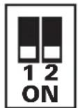
The enclosure can be set to function in one of four modes; Normal, JBOD, RAID 0 and RAID 1, giving you the flexibility to access your data in whatever way works best for you. The available modes are described below with their corresponding dip switch setting displayed on the left side of the image.
Normal Mode – This mode treats both hard drives as separate disks, allowing them to be accessed independently of each other. Your computer will recognize them as if they were flash drives being plugged into separate USB ports, not changing them in any way.

flowchart
graph LR
    A["1 ON"] --> B["2 Disk Volume"]
    B --> C["SATA1 1000G SATA2 750G SATA1 1000G SATA2 750G"]
    C --> D["2 Disk Volume"]
JBOD Mode – This mode combines the two hard drives into one large drive for the purpose of increased storage space. Data is stored on one drive at a time, so when the first one is full, the next one begins to be used. The computer's operating system will recognize them as a single drive.

flowchart
graph LR
    A["1 2 ON"] --> B["2 Disk Volume"]
    B --> C["SATA1 1000G SATA2 750G 1000G+750G=1750G"]
    C --> D["1 Disk Volume"]
RAID 0 Mode – This mode combines the two hard drives into one large drive for the dual purpose of increased storage space and performance. In this mode, data is split amongst the two drives simultaneously, improving the read/write performance. The risk in using this mode is that failure of one disk will result in total data loss. When using this mode, it is recommended that you use hard drives with the same capacities. If hard drives of different capacities are used, the smaller hard drive will be doubled in size with the remaining space on the larger hard drive going unused.

flowchart
graph LR
    A["1 ON 12"] --> B["2 Disk Volume"]
    B --> C["SATA1 1000G SATA2 750G 750Gx2=1500G"]
    C --> D["1 Disk Volume"]
RAID Mode
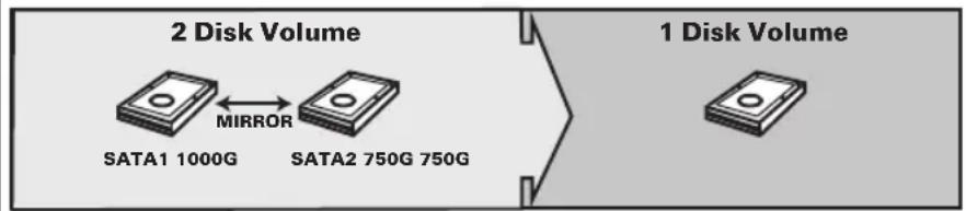
RAID 1 Mode – This mode creates two mirror disk drives for the purpose of data redundancy. If one drive fails, the other drive serves as a backup. When using this mode, it is recommended that you use hard drives with the same capacities. If hard drives of different capacities are used, the storage capacity will be limited to that of the smaller drive with the remaining space on the larger drive going unused.
Note: In RAID 1 mode, if one drive fails, the red LED to the right of the hard drive tray will blink. Replacing the drive will cause the enclosure to automatically enter rebuild mode, in which the red LED will continue to blink to indicate the RAID 1 array is being rebuilt. Depending on the size of the drives, this may take several hours to a full day.
flowchart
graph LR
    A["2 Disk Volume"] -->|MIRROR| B["SATA1 1000G"]
    A --> C["SATA2 750G 750G"]
    D["1 Disk Volume"] -->|Mirror| E["SATA2 750G 750G"]
Setting the RAID Mode
Note: Make sure you back up any important data prior to changing the enclosure's RAID mode. Initializing the RAID mode will erase all data on your hard drives.
When Powered On:
- Install the hard drives in the enclosure according to the Installation Instructions section in this manual, then power on the unit.
- By default, the dip switches on the back of the unit are both set to the OFF (Up) position, which will display the hard drives in Normal mode.
- Set the dip switches on the back of the unit according to the desired mode. See the RAID Mode section in this manual for each mode's dip switch configuration.
Note: When changing from RAID 1 mode to another mode, you must first switch to RAID 0 mode. Once set to RAID 0 mode, you can change to any other mode.
-
After setting the dip switches accordingly, press and release the Reset button on the back of the unit.
-
After a couple of seconds, your drives will be configured according to the mode you have selected. The new drive will not be formatted, and will need to be formatted using your computer's Disk Management utility.
Setting the RAID Mode
When Powered Off:
- Install the hard drives in the enclosure according to the Installation Instructions section in this manual, but do not power on the unit.
- By default, the dip switches on the back of the unit are both set to the OFF (Up) position, which will display the hard drives in Normal mode.
-
Set the dip switches on the back of the unit according to the desired mode. See the RAID Mode section in this manual for each mode's dip switch configuration.
Note: When changing from RAID 1 mode to another mode, you must first switch to RAID 0 mode. Once set to RAID 0 mode, you can change to any other mode. -
After setting the dip switches accordingly, power on the unit.
-
After a couple of seconds, your drives will be configured according to the mode you have selected. The new drive will not be formatted, and will need to be formatted using your computer's Disk Management utility.
Installation Instructions
-
Remove a tray by pressing down the release tabs on its front and pulling it from the enclosure.
-
Remove the side snaps from each side of the tray.
3a. For a 3.5" HDD – Place the hard drive so the SATA connector faces the rear, and the screw holes rest on top of the plastic pillars located on the side of the tray. Re-insert the side snaps on each side of the tray to secure the drive in place.

natural_image
Black plastic hard drive housing with four square cutouts and a separate cylindrical component, labeled 'step 2' (no text or symbols on the components themselves)3b. For a 2.5" HDD – Place the hard drive so that the SATA connector faces the rear, lining up the screw holes on the bottom of the drive with those on the tray. Secure the drive to the tray using the included screws.
-
Fully insert the tray into the enclosure until it locks into place.
-
Repeats steps 1 through 4 to install a second hard drive.
-
Connect the enclosure to your computer using the included USB 3.0 cable.
-
Connect the included power supply to the enclosure, and plug it into a Tripp Lite Surge Protector, Power Distribution Unit (PDU) or Uninterruptible Power Supply (UPS).
-
Press the power button on the front of the enclosure to power the unit on. The blue Power LED under the button will illuminate to indicate the unit is powered on. The blue LEDs on the right front of each hard drive tray will illuminate solid to indicate the drive is functioning properly. They will blink to indicate that RAID Mode has crashed or errors have occurred during RAID rebuilding. The red LEDs on the right front of each hard drive tray will blink to indicate a data transfer is taking place.
Warranty and Product Registration
1-Year Limited Warranty
TRIPP LITE warrants its products to be free from defects in materials and workmanship for a period of one (1) year from the date of initial purchase. TRIPP LITE's obligation under this warranty is limited to repairing or replacing (at its sole option) any such defective products. To obtain service under this warranty, you must obtain a Returned Material Authorization (RMA) number from TRIPP LITE or an authorized TRIPP LITE service center. Products must be returned to TRIPP LITE or an authorized TRIPP LITE service center with transportation charges prepaid and must be accompanied by a brief description of the problem encountered and proof of date and place of purchase. This warranty does not apply to equipment, which has been damaged by accident, negligence or misapplication or has been altered or modified in any way.
EXCEPT AS PROVIDED HEREIN, TRIPP LITE MAKES NO WARRANTIES, EXPRESS OR IMPLIED, INCLUDING WARRANTIES OF MERCHANTABILITY AND FITNESS FOR A PARTICULAR PURPOSE.
Some states do not permit limitation or exclusion of implied warranties; therefore, the aforesaid limitation(s) or exclusion(s) may not apply to the purchaser.
EXCEPT AS PROVIDED ABOVE, IN NO EVENT WILL TRIPP LITE BE LIABLE FOR DIRECT, INDIRECT, SPECIAL, INCIDENTAL OR CONSEQUENTIAL DAMAGES ARISING OUT OF THE USE OF THIS PRODUCT, EVEN IF ADVISED OF THE POSSIBILITY OF SUCH DAMAGE. Specifically, TRIPP LITE is not liable for any costs, such as lost profits or revenue, loss of equipment, loss of use of equipment, loss of software, loss of data, costs of substitutes, claims by third parties, or otherwise.
Use of this equipment in life support applications where failure of this equipment can reasonably be expected to cause the failure of the life support equipment or to significantly affect its safety or effectiveness is not recommended. Do not use this equipment in the presence of a flammable anesthetic mixture with air, oxygen or nitrous oxide.
PRODUCT REGISTRATION
Visit www.triplite.com/warranty today to register your new Tripp Lite product. You'll be automatically entered into a drawing for a chance to win a FREE Tripp Lite product!*
* No purchase necessary. Void where prohibited. Some restrictions apply. See website for details.
FCC Notice, Class B
This device complies with part 15 of the FCC Rules. Operation is subject to the following two conditions: (1) This device may not cause harmful interference, and (2) this device must accept any interference received, including interference that may cause undesired operation.
Note: This equipment has been tested and found to comply with the limits for a Class B digital device, pursuant to part 15 of the FCC Rules. These limits are designed to provide reasonable protection against harmful interference in a residential installation. This equipment generates, uses and can radiate radio frequency energy and, if not installed and used in accordance with the instructions, may cause harmful interference to radio communications. However, there is no guarantee that interference will not occur in a particular installation. If this equipment does cause harmful interference to radio or television reception, which can be determined by turning the equipment off and on, the user is encouraged to try to correct the interference by one or more of the following measures:
- Reorient or relocate the receiving antenna.
- Increase the separation between the equipment and receiver.
- Connect the equipment into an outlet on a circuit different from that to which the receiver is connected.
- Consult the dealer or an experienced radio/TV technician for help.
Any changes or modifications to this equipment not expressly approved by Tripp Lite could void the user's authority to operate this equipment.
WEEE Compliance Information for Tripp Lite Customers and Recyclers (European Union)
Under the Waste Electrical and Electronic Equipment (WEEE) Directive and implementing regulations, when customers buy new electrical and electronic equipment from Tripp Lite they are entitled to:
- Send old equipment for recycling on a one-for-one, like-for-like basis (this varies depending on the country)
- Send the new equipment back for recycling when this ultimately becomes waste
Tripp Lite has a policy of continuous improvement. Specifications are subject to change without notice.
Notes


1111 W. 35th Street, Chicago, IL 60609 USA • www.tripplite.com/support
- Dual-Bay USB 3.0 to SATA Hard Drive RAID Enclosure
- PROTECT YOUR INVESTMENT!
- Package Contents:
- Features:
- System Requirements:
- RAID Mode
- Setting the RAID Mode
- When Powered On:
- When Powered Off:
- Installation Instructions
- Warranty and Product Registration
- 1-Year Limited Warranty
- PRODUCT REGISTRATION
- FCC Notice, Class B
- WEEE Compliance Information for Tripp Lite Customers and Recyclers (European Union)
- Notes
Brand : Tripp Lite
Model : U357-002
Category : NAS