D8010W - Video projector VIVITEK - Free user manual and instructions
Find the device manual for free D8010W VIVITEK in PDF.

User questions about D8010W VIVITEK
0 question about this device. Answer the ones you know or ask your own.
Ask a new question about this device
Download the instructions for your Video projector in PDF format for free! Find your manual D8010W - VIVITEK and take your electronic device back in hand. On this page are published all the documents necessary for the use of your device. D8010W by VIVITEK.
USER MANUAL D8010W VIVITEK
natural_image
Illustration of a projector with a circular vent and ventilation slots (no text or symbols)CONTENTS
COPYRIGHT INFORMATION 4
—Copyright 4
—Disclaimer 4
—About this manual 4
IMPORTANT SAFETY INSTRUCTIONS 5
—Disposal of old electrical and electronic equipment 6
— Important Recycle Instructions: 6
INTRODUCTION 7
—About This Manual 7
—Description, Features and Benefits 7
—Parts List 8
CONTROLS AND FUNCTIONS 9
—D8800/D8900/D8010W at a Glance 9
—I/O Panel 10
—KEYPAD 11
—Remote control 12
— To install batteries in the remote control 13
— Range of effective remote control signal reception 13
INSTALLATION CONSIDERATIONS 14
—Ambient Light 14
—Throw Distance 14
—Modes of installation 15
— Allow at least 50 cm clearance around the exhaust vent. 16
LENS SHIFT 17
— Vertical Lens Shift 17
—Horizontal Lens Shift 17
CONNECTING THE PROJECTOR TO OTHER DEVICES. 18
—HDMI Connection 18
—Trigger connection 18
—IR Input connection 19
— S-VIDEO, VIDEO connection 19
—COMPONENT connection 20
—RS-232 Connection 20
—LAN Connection 21
START USING THE PROJECTOR - ADJUSTMENTS 22
—Connecting to AC Power 22
—Turning on the Power 22
—Changing the OSD Language 23
—Adjusting the Picture Orientation 23
—Lens Adjustments 24
—Selecting An Input Source 25
—Selecting an Aspect Ratio 25
—Using the OSD 25
START USING THE PROJECTOR - OSD INTRODUCTION 26
—OSD Menu Tree 26
—OSD Introduction - INPUT 28
—OSD Introduction - PICTURE 31
—OSD Introduction - LAMPS 34
—OSD Introduction - ALIGNMENT 35
—OSD Introduction - CONTROL 39
—OSD Introduction - SERVICE 45
CHANGE LAMP 47
— To replace the projector lamp1 47
— To replace the projector lamp2 48
CHANGE LENS 49
— To replace the projector Lens 49
CHANGE FILTER 51
— To replace the Filter on the left side of the projector 51
— To replace the Filter on the right side of the projector 52
— Change the color wheel 53
LED STATUS 54
—Power LED 54
—Status LED 54
—Lamp1/Lamp2 LED 54
—Temp LED 54
—Shutter LED 54
SPECIFICATIONS 55
SERIAL INTERFACE SPECIFICATIONS 56
— Transfer Specifications 56
—RS-232 Commands 56
—IR Codes and Key names 56
—Operations Commands 57
DIMENSIONS 64
SUPPORTED TIMINGS 65
PROJECTION DISTANCE AND SCREEN SIZE 66
—Optional Lens
COPYRIGHT INFORMATION
COPYRIGHT
This publication, including all photographs, illustrations and software, is protected under international copyright laws, with all rights reserved. Neither this manual, nor any of the material contained herein, may be reproduced without written consent of the manufacturer. The Vivitek logo is a trademark of “Vivitek Corporation.” © Copyright 2012
DISCLAIMER
The information in this document is subject to change without notice. The manufacturer makes no representations or warranties with respect to the contents hereof and specifically disclaims any implied warranties of merchantability or fitness for any particular purpose. The manufacturer reserves the right to revise this publication and to make changes from time to time in the content here without obligation of the manufacturer to notify any person of such revision or changes.
ABOUT THIS MANUAL
This manual is intended for end users and describes how to install and operate the DLP projector. Wherever possible, relevant information such as an illustration and its description has been kept on one page. This printer-friendly format is both for your convenience and to help save paper, thereby protecting the environment. It is suggested that you only print sections that are relevant to your needs.
IMPORTANT SAFETY INSTRUCTIONS
Thank you for your purchase of this quality product! For best performance, please read this manual carefully as it is your guide through the menus and operation.
- Read and Keep these instructions.
- Heed all warnings.
- Follow all instructions.
- Do not use this apparatus near water. And not install near any heat sources such as radiators, heat registers, stoves, or other apparatus (including amplifiers) that produce heat.

text_image
Illustration showing fire extinguishing, steam heating, cooking with pots, and a prohibition symbol.- Clean only with a dry cloth.
- Do not block any of the ventilation openings. Install in accordance with the manufacturer's instructions.
- Do not defeat the safety purpose of the polarized or grounding type plug. A polarized plug has two blades with one wider than the other. A grounding type plug has two blades and a third grounding prong. The wide blade or the third prong is provided for your safety. When the provided plug does not fit into your outlet, consult an electrician for the replacement of the obsolete outlet.
- Protect the power cord from being walked on or pinched particularly at plugs, convenience receptacles and the point where they exit from the apparatus.
- Only use the attachments/accessories specified by the manufacturer.
- Use only with a cart, stand, tripod, bracket or table specified by the manufacturer or sold with the apparatus. When a cart is used, use caution when moving the cart/apparatus to avoid injury from tip-over.

- Unplug this apparatus during lightning storms or when unused for long periods of time.

flowchart
graph LR
    A["Cloud with lightning"] --> B["Ship with water"]
    B --> C["Airplane with cargo"]
    C --> D["Hand interaction with hand"]
- Refer all servicing to qualified service personnel. Servicing is required when the apparatus has been damaged in any way, such as power supply cord or plug is damaged, liquid has been spilled or objects have fallen into the apparatus, the apparatus has been exposed to rain or moisture, does not operate normally, or has been dropped.
- The +12V trigger only outputs 12V DC signal for triggering. Do not connect to any other power input or output. This could cause damage to this unit.
- Keep the packing material in case the equipment should ever need to be shipped.
- Never look into the lens when the projector is on.

text_image
AVOID EYE CONTACT TO THE LIGHTDISPOSAL OF OLD ELECTRICAL AND ELECTRONIC EQUIPMENT
(Applicable throughout the European Union and other European countries with separate collection programs)
This symbol found on your product or on its packaging, indicates that this product should not be treated as household waste when you wish to dispose of it. Instead, it should be handed over to an applicable collection point for the recycling of electrical and electronic equipment. By ensuring this product is disposed of correctly, you will help prevent potential negative consequences to the environment and human health, which could otherwise be caused by inappropriate disposal of this product. The recycling of materials will help to conserve natural resources. This symbol is only valid in the European Union. If you wish to discard this product, please contact your local authorities or dealer and ask for the correct method of disposal.

natural_image
Symbol of a trash bin crossed with no text or labels, accompanied by a solid black rectangle below (no text or symbols present)IMPORTANT RECYCLE INSTRUCTIONS:
Lamp(s) inside this product contain mercury. This product may contain other electronic waste that can be hazardous if not disposed of properly. Recycle or dispose in accordance with local, state, or federal Laws. For more information, contact the Electronic Industries Alliance at WWW.EIAE.ORG. For lamp specific disposal information check WWW.LAMPRECYCLE.ORG.

INTRODUCTION
ABOUT THIS MANUAL
This User's Manual describes how to install, set up and operate the D8800/D8900/D8010W. Throughout this manual, the Projector is referred to as the "D8800/D8900/D8010W."
Target Audience Vivitek has prepared this manual to help installers and end users get the most out of the D8800/D8900/D8010W. Vivitek has made every effort to ensure that this manual is accurate as of the date it was printed. However, because of ongoing product improvements and customer feedback, it may require updating from time to time. You can always find the latest version of this and other Vivitek product manuals on-line, at www.vivitekcorp.com.
DESCRIPTION, FEATURES AND BENEFITS
The Vivitek D8800/D8900/D8010W provide state-of-the-art technology for full HD (1920 x 1200, WUXGA 16:10) native resolution for crystal clear, pristine images. The D8800/D8900/D8010W offer incredibly high definition images at today's highest available resolutions. Equipped with precision optics, the D8800/D8900/D8010W include zoom, focus and lens shift controls for a throw range of 1.85:1 to 2.40:1. For a smaller throw distance (1.56:1 to 1.86:1), the D8800/D8900/D8010W can be fitted with a varying optics package (optional) to meet different requirements. Exceptional scaling and film-to-video (3:2 pull-down) conversion is easily achieved. Combined with Vivitek's sophisticated parameters for white balancing, the D8800/D8900/D8010W's proprietary de-interlacing technology provides the highest level of development for gray-scale and color balancing and artifact-free images. Completing this engineering marvel are discrete infrared (IR) and RS-232 control, power and source selection controls for seamless, flexible operation.
{ Key Features and Benefits
The D8800/D8900/D8010W offer these key features and benefits:
—Native Resolution: 1920 x 1080 (16:10 Native Aspect Ratio).
—DLP system using high-performance Digital Micromirror Device (DMD).
— HDMI 1.3 Input with High-bandwidth Digital Content Protection (HDCP).
—HDTV Compatible.
— Excellent Video Processing on progressive and interlaced video inputs.
{ Green Product with:
— Lead free solder used for soldering including circuit and component electronics.
—Lead free glasses and coatings.
—Recycled paper used in the user manuals and packing cartons.
— Energy Saving: High efficiency power switching and less than 0.5W power consumption in standby mode.
■ Additional Features of the D8800/D8900/D8010W
—Horizontal and vertical lens shift.
—Keystone adjustment.
PARTS LIST
Your D8800/D8900/D8010W is shipped with the following items, if any items are missing or damaged, please contact your dealer or Vivitek Customer Service.
| Accessory Box List D8800/D8900/D8010W | ||||
| Item M | Manual Assy Q'ty EU/ASIA/US/TWN China | |||
| 1 | CD-ROM 1 | ● | ● | |
| 2 | WARRANTY CARD (US/EUR) 1 | ● | - | |
| 3 | WARRANTY CARD (CN) | 1 | - | ● |
| 4 | RoHS Card (CN) | 1 | - | ● |
| 5 | QC Pass Card (CN) | 1 | - | ● |
| 6 | Important Information (CN) | 1 | ● | ● |
| 7 | POWER CORD 125Vac USA | 1 | ● | - |
| 8 | POWER CORD 250Vac EUR | 1 | ● | - |
| 9 | POWER CORD 250Vac CHINA | 1 | - | ● |
| 10 | VGA Signal cable | 1 | ● | ● |
| 11 | SCREW M M4*0.7*7o PAN C SUS | 1 | ● | ● |
| 12 | BATTERY | 2 | ● | ● |
| 13 | REMOTE | 1 | ● | ● |
| 14 | MODULE COLOR TYPE COLOR WHEEL | 1 | ● | ● |
CONTROLS AND FUNCTIONS
D8800/D8900/D8010W AT A GLANCE
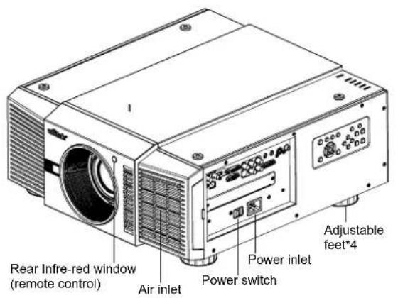
text_image
Rear Infre-red window (remote control) Air inlet Power switch Power inlet Adjustable feet*4
text_image
Air outlet Air outlet Air outlet Air inlet
natural_image
Top-down schematic of a battery pack with four circular components and mounting holes (no text or symbols)—Air outlet
Warm air exits the projector through this vent. Ensure that it is not blocked.
—Air inlet
Internal fans draw cool air into the projector through this vent.
—Adjustable feet
Use these when the projector is installed in a table-top configuration to level the image and/or adjust the projection angle.
—Power Inlet
For input power from wall outlet to projector.
—Rear Infre-red window
For receive the remote controller's message.
I/O PANEL
text_image
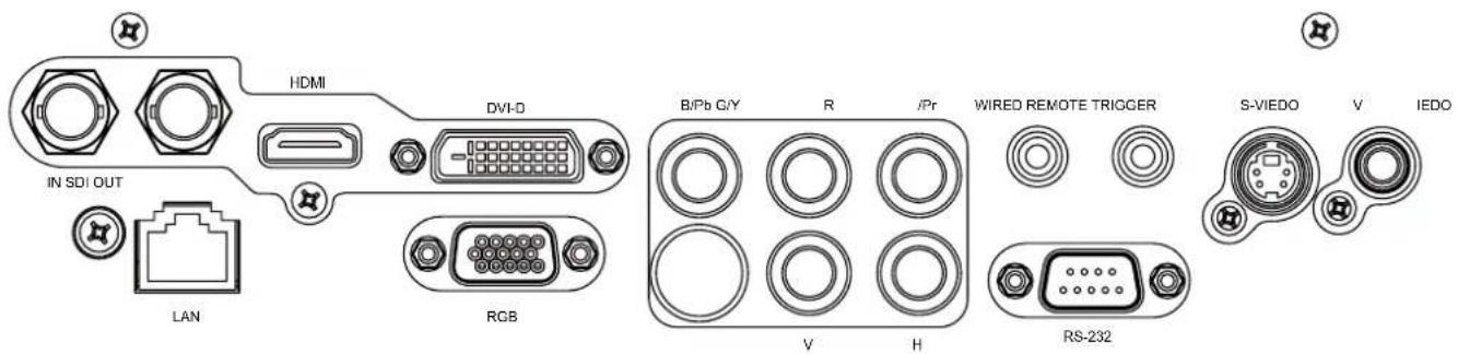
HDMI DVI-D IN SDI OUT LAN RGB B/Pb G/Y R /Pr WIRED REMOTE TRIGGER S-VIEDO V IEDO V H RS-232—SDI
Connect a BNC cable from a serial digital interface (SDI) device.
—HDMI
Connect an HDMI source.
—DVI
Connect a DVI source.
—Component
Connect a Component (YUV HS/VS-CS) source.
WIRED REMOTE
Wired input from a Niles- or Xantech-compatible, infrared (IR) repeater system.
—TRIGGER
(3.5-mm, mini phone jack) Offers 12 (+/- 1.5) V of output for 350mA monitor relay with short circuit protection.
—S-VIDEO
A standard S-Video input for connecting a DVD player, satellite receiver or Super VHS (S-VHS) VCR.
—VIDEO
Standard composite video input for connecting a VCR, laser disc player or other composite video source. Also provides composite sync input for RGBS sources.
—LAN
Connect an RJ45 ethernet cable.
—RGB
Provides a standard, 15-pin VGA-style connection to either an RGB or component high-definition source, or to a personal computer.
The D8800/D8900/D8010W automatically detect the input signal resolution.
RS-232
9-pin D-sub connector for interfacing with a PC or home theater automation/control system.
KEYPAD
POWER INPUT AUTO SYNC ASPECT OPEN CLOSE
text_image
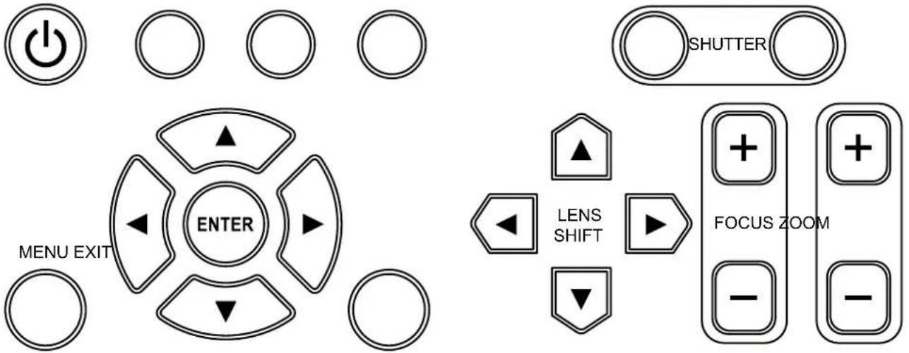
MENU EXIT ENTER SHUTTER LENS SHIFT FOCUS ZOOM—POWER
Use the button to turn on/off the projector.
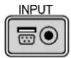
—INPUT
Press to select a video source. HDMI, DVI, VGA, Component / BNC Composite, S-Video or 3D-SGI.
Press this to re-acquire the current active source.
—ASPECT
Press this to change the aspect ratio of the current image.
—SHUTTER
Use the buttons to turn on/off shutter.
—MENU
Press this button to show or hide the OSD menu.
— ENTER, ▲, ▼, ◀, ▶
Use these buttons to select items or settings, adjust settings or switch display patterns.
—EXIT
Press this to go one menu higher or exit the OSD menu.
—LENS SHIFT
Button to shift control of the lens, up/down or left/right.
—FOCUS
Button to focus the projected image.
—ZOOM
Button to zoom in/out the lens.
REMOTE CONTROL
text_image
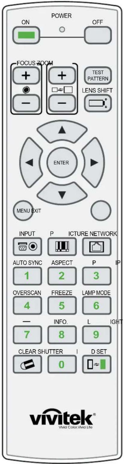
POWER ON OFF FOCUS ZOOM TEST PATTERN LENS SHIFT ENTER MENU EXIT INPUT P ICTURE NETWORK AUTO SYNC ASPECT P IP 1 2 3 OVERSCAN FREEZE LAMP MODE 4 5 6 - INFO. L IGHT 7 8 9 CLEAR SHUTTER I D SET vivitek® Vida Color:Vida Life— ON
Use this button to turn the projector on.
— OFF
Use this button to turn the projector off.
- FOCUS
Focuses the projected images.
— ZOOM
Zoom in/out the projected image.
— TEST PATTERN
Use this to enter test pattern menu.
— LENS SHIFT
Button to shift control of the lens, up/down or left/right.
— ENTER, ▲, ▼, ◀, ▶
Use these buttons to select items or settings, adjust settings or switch display patterns. ENTER: Press to select a highlighted menu item or confirm a changed setting.
— MENU
Press this button to show or hide the OSD menu.
— EXIT
Press this to go one menu higher or exit the OSD menu.
- INPUT
Press to select a input source.
— PICTURE
Starts the PICTURE function.
— NETWORK
Press this to enter the Network (LAN) menu.
— AUTO SYNC
Press this to re-acquire the current active source.
ASPECT
Selection Button: Press this button repeatedly to select one of the following aspect ratios: 16 : 9: For viewing 16:9 DVDs or HDTV programs in their native aspect ratio.
— PIP
Press this to display the picture-in-picture screen.
OVERSCAN
Press to select an overscan mode.
FREEZE
Freeze/unfreezes the on-screen picture.
— LAMP MODE
Press this to select a higher or lower brightness setting.
— INFO.
Starts the SERVICE function.
— LIGHT
Press this to turn on remote control backlight.
— CLEAR
Not available
— SHUTTER
Use the button to turn on/off shutter.
— ID SET
Not available
Notes on Remote Control Operation
— In most situations, you can simply point the remote control at the screen which will reflect the IR signal from the re-mote back toward the IR receiver on the projector. In some cases, however, ambient conditions may prevent this. If so, point the remote control at the projector and try again.
— If the effective range of the remote control decreases, or it stops working, replace the batteries with new ones.
— The remote control may fail to operate if the infrared remote sensor is exposed to bright sunlight or fluorescent lighting.
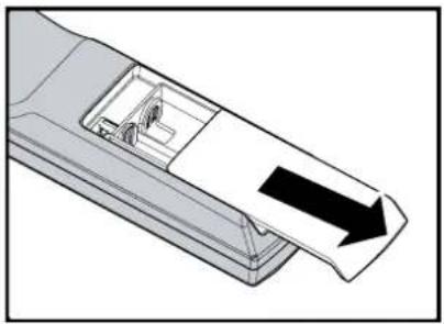
TO INSTALL BATTERIES IN THE REMOTE CONTROL
STEP 1 STEP 2 STEP 3
natural_image
Diagram of a device's internal structure with an arrow indicating direction (no text or symbols present)
natural_image
Diagram of a battery inside a remote control casing with arrows indicating rotation (no text or symbols)
natural_image
Diagram of a vehicle's side panel with an arrow indicating direction (no text or symbols)- Slide the battery compartment cover in the direction of the arrow to remove it.
- Install two AA batteries with the correct polarity.
- Replace the cover.
Notes on Batteries
— Make sure that the battery polarities are correct when installing the batteries.
— Do not mix an old battery with a new one or different types of batteries.
If you will not use the remote control for a long time, remove the batteries to avoid damage from battery leakage.
RANGE OF EFFECTIVE REMOTE CONTROL SIGNAL RECEPTION
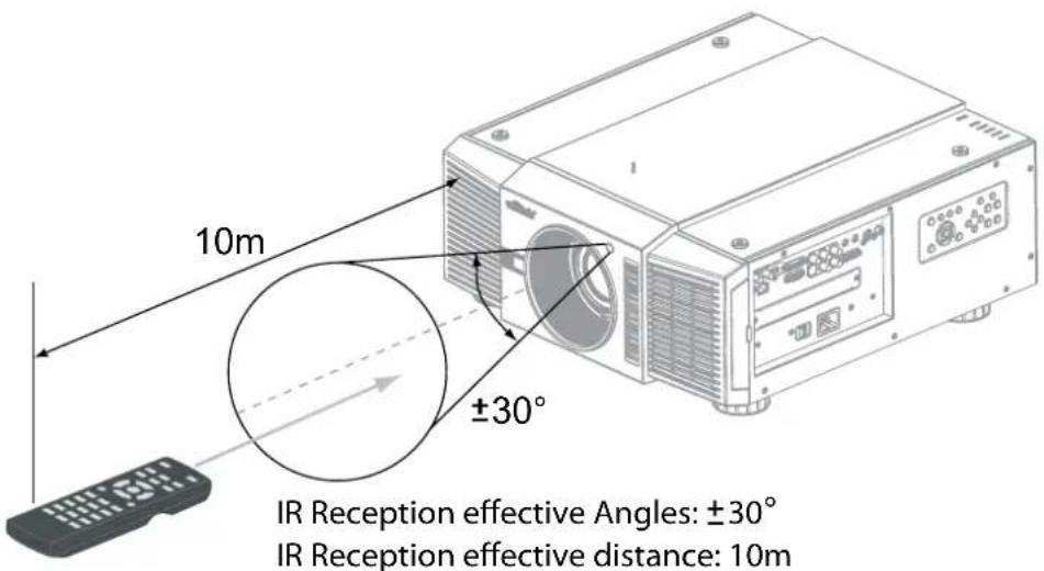
text_image
10m ±30° IR Reception effective Angles: ±30° IR Reception effective distance: 10mNote:
Avoid placing the remote control at places of high temperature or humidity as it could cause the remote control to malfunction.
INSTALLATION CONSIDERATIONS
PROPER INSTALLATION OF YOUR PROJECTOR WILL ENSURE THE QUALITY OF YOUR DISPLAY. WHETHER YOU ARE INSTALLING A PROJECTOR TEMPORARILY OR PERMANENTLY, YOU SHOULD TAKE THE FOLLOWING INTO ACCOUNT TO ENSURE YOUR PROJECTOR PERFORMS OPTIMALLY.
AMBIENT LIGHT
In general, minimize or eliminate light sources directed at the screen. Contrast ratio in your images will be noticeably reduced if light directly strikes the screen, such as when a shaft of light from a window or floodlight falls on the image. Images may then appear washed out and less vibrant.
Requires separate room Installation cost is usually higher.
THROW DISTANCE
Throw distance is the distance measured from the front of the projector to the screen. This is an important calculation in any projector installation as it determines whether or not you have enough room to install your projector with a de-sired screen size and if your image will be the right size for your screen. You can quickly estimate the throw distance by taking the width of the screen and multiplying it by the lens throw ratio; see the image as following. The result of this calculation tells you roughly how far back the projector should be positioned from the screen in order to project a focused image large enough to fill the screen.
Throw Distance (TD) = Screen Width (W) x Throw Ratio (TR)

text_image
Screen Width (W) Throw Distance (TD)Two models of the D8800/D8900/D8010W are available, one with 1.56-1.86:1 lens and the other with 1.85-2.40:1 lens. With optional zoom adaptors throw ratios of 1.24 - 3.0 can be achieved. The standard D8800/D8900/D8010W offer throw ratios between 1.85:1 and 2.40:1. With the optional, short-throw lens, the D8800/D8900/D8010W offer throw ratios between 1.56:1 and 1.86:1.
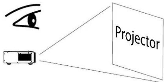
MODES OF INSTALLATION
■ Frontal projection - desktop installation
Advantages: easy to install can be easily moved or adjusted easy to operate.
Disadvantage: occupies floor space and limits seating capacity.
■ Rear projection - desktop installation
Advantage: the projector is completely hidden from plain view the projector can be easily operated this setup usually offers better reduction of ambient noise.
Disadvantage: requires an additional room for installation relatively higher costs for installation.
■ Frontal projection - ceiling mode
Advantage: does not occupy floor space does not draw attention to it. Eliminates the possibility that someone would accidentally move the projector.
Disadvantage: stricter installation requirements and conditions; care should be taken during the installation to ensure the projector has been securely mounted. Operation of the projector becomes inconvenient without the remote control.
■ Rear projection - ceiling mode
Advantage: the projector is completely hidden from plain view this setup usually offers better reduction of ambient noise.
Disadvantage: requires an additional room for installation. Stricter installation requirements and conditions; care should be taken during the installation to ensure the projector has been securely mounted. Operation of the projector becomes inconvenient without the remote control.
text_image
Projector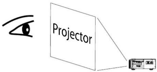
text_image
Projector
text_image
Projector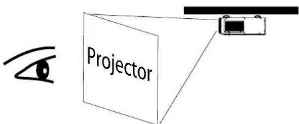
text_image
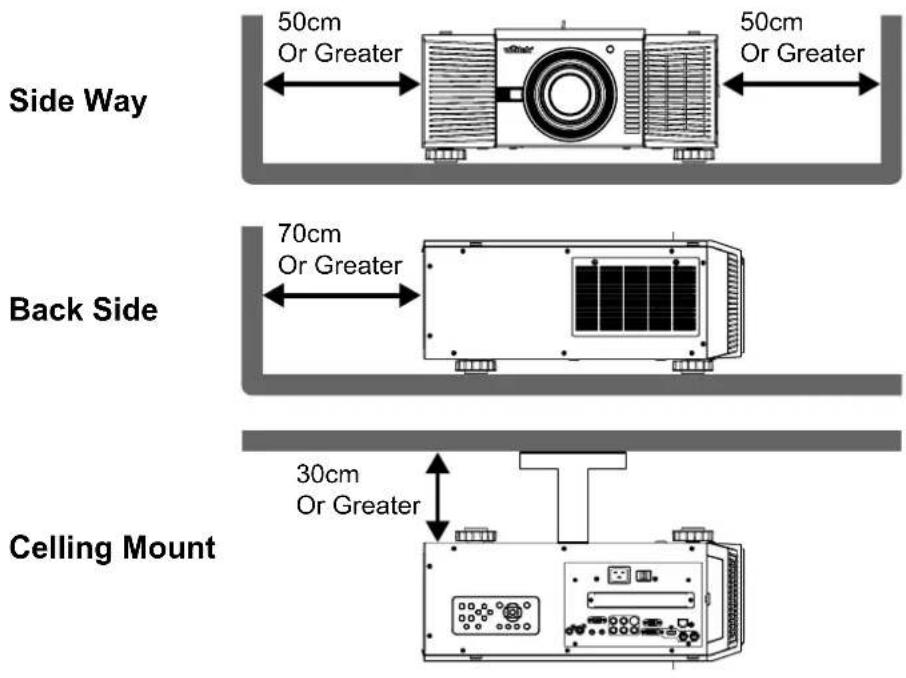
ProjectorALLOW AT LEAST 50 CM CLEARANCE AROUND THE EXHAUST VENT.
The device need to have enough space to prevent issues as stated in this image.
text_image
50cm Or Greater 50cm Or Greater Side Way 70cm Or Greater Back Side 30cm Or Greater Ceiling MountLENS SHIFT
VERTICAL LENS SHIFT
The D8800/D8900/D8010W have a lens shift capability which allows the vertical movement of the image without moving the projector. Lens shift is generally expressed as a percentage of the screen height. For ceiling mounted projectors, the lens can be moved 50% (0.5V) downward, while the lens can be moved 50% (0.5V) up or down on a desktop mounted projector.

text_image
Desktop Front Projection Vertical Shift Height of projected image Max. 0.5V Max. 0.5V 1V Ceiling Front Projection Vertical Shift Max. 0.5V 1VNote:
This is a general example of lens shift. Lenses vary in their shift capabilities. No particular lens or projector is used in this example.
HORIZONTAL LENS SHIFT
The D8800/D8900/D8010W have a lens shift capability which allows the horizontal movement of the image without moving the projector. The lens can be moved 10% (0.1H) to the right or left within the housing.

text_image
Max. 0.5V 1V Normal Projection Position 0.1H Width of projected image 0.1H H Shift to Left Shift to RightNote::
This is a general example of lens shift. Lenses vary in their shift capabilities. No particular lens or projector is used in this example.
CONNECTING THE PROJECTOR TO OTHER DEVICES.
Proceed as follows to connect the D8800/D8900/D8010W to your video sources, external controller(s) - if present - and AC power. When connecting your equipment: • Use the correct signal cables for each source. • Ensure that the cables are securely connected. Tighten the thumbscrews on connectors that have them. Connecting Source Components to the D8800/D8900/D8010W Connect your video sources to the D8800/D8900/D8010W as shown and described in the sections that follow.
HDMI CONNECTION

text_image
HDMI DVI-D IN SDI OUT LAN RGB B/Pb G/Y R /Pr WIRED REMOTE TRIGGER V H RS-232 S-VIEDO V IEDO DVI Source(s) (BD/HD-DVD/DVD Player, HD SetTop Box, Game Console etc.)TRIGGER CONNECTION
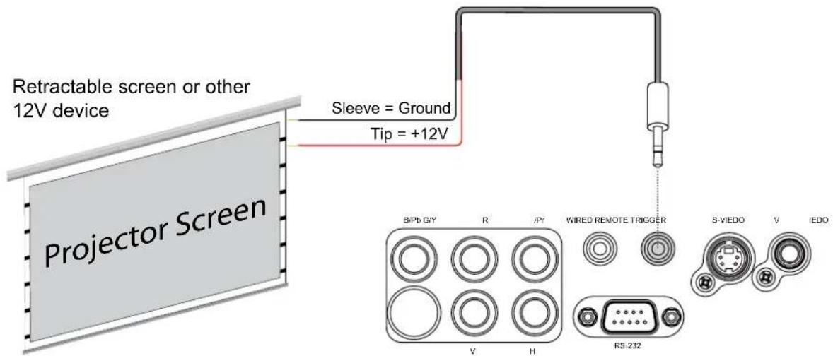
If your home theatre system includes a projector screen, screen cover or other 12V Trigger equipment, please connect such device/equipment to the projector's 12V Trigger output as illustrated. After you have done so, your screen will lower automatically whenever you turn on your projector for your convenience.
text_image
Retractable screen or other 12V device Sleeve = Ground Tip = +12V Projector Screen B/Pb G/Y R /P/ WIRED REMOTE TRIGGER S-V/EDO V I/EDO V H RS-232IR INPUT CONNECTION
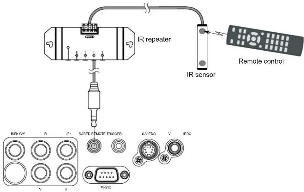
If infrared signals from the remote control cannot reach the projector due to excessive distance or obstructions such as walls or cabinet doors, you can connect an external IR repeater system to the IR INPUT on the D8800/D8900/D8010W to extend the range of the remote control.
text_image
IR repeater IR sensor Remote control B/Ph G/Y R /Pr WIRED REMOTE TRIGGER S-VIEDO V IEDO V H RS-232If the image input device offers both S-Video and Video connection, it is recommended that you choose S-Video to obtain better image quality. If both the S-Video and Video inputs are connected to the projector, the projector will prioritize S-Video signal input and image from the Video input will not be played.
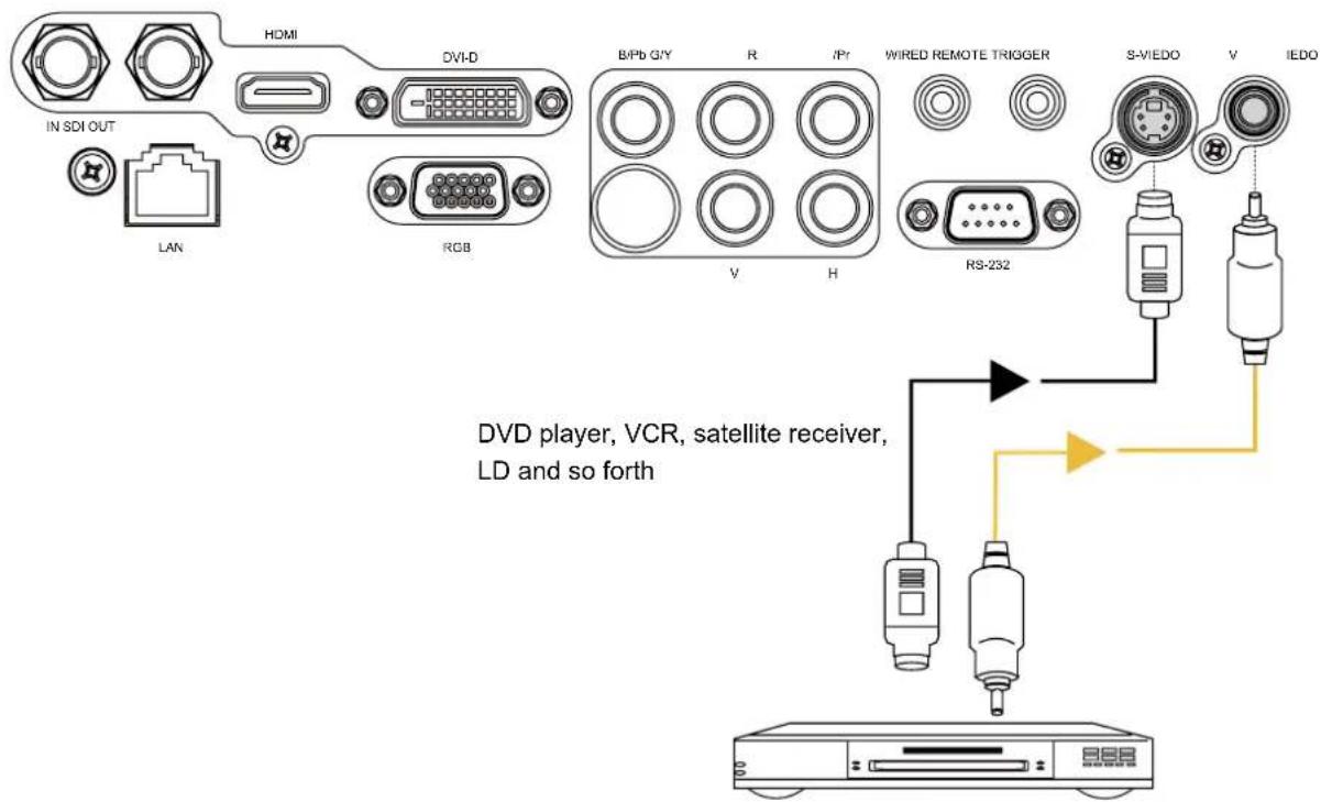
text_image
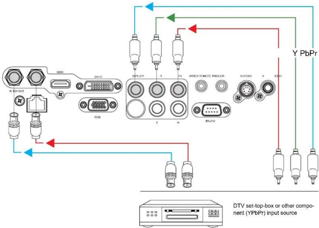
IN SDI OUT LAN HDMI DVI-D RGB B/Pb G/Y R /Pr WIRED REMOTE TRIGGER RS-232 S-VIEDO V IEDO DVD player, VCR, satellite receiver, LD and so forthCOMPONENT CONNECTION
Take the 3/5 cabled RGB component video connectors from the source equipment to the projector's COMPONENT jacks.
flowchart
graph TD
    A["In SOI OUT"] --> B["HDAC"]
    B --> C["DA-0"]
    C --> D["RGB"]
    D --> E["RPB GY"]
    E --> F["V"]
    E --> G["H"]
    F --> H["WRED REMOTE TRIGGER"]
    G --> H
    H --> I["RS-232"]
    I --> J["S-VEDD"]
    I --> K["V"]
    I --> L["IEDO"]
    J --> M["Y PbPr"]
    K --> M
    L --> M
    style A fill:#f9f,stroke:#333
    style M fill:#bbf,stroke:#333
    note bottom
        DTV_set_top_box
        (YPbPr)
        input_source
    end
RS-232 CONNECTION
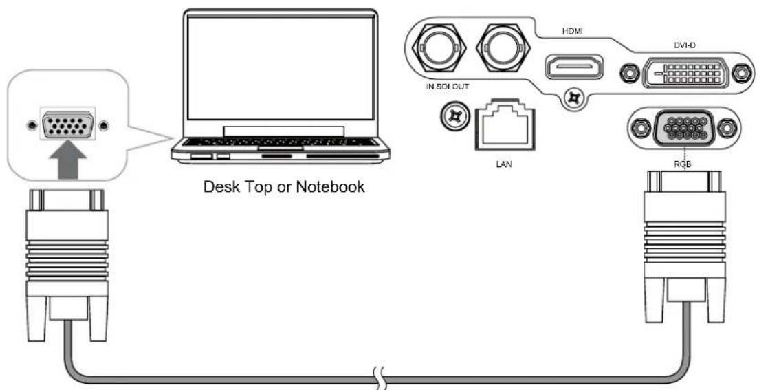
Connect a PC or home theater control/automation system (if present) to the RS-232 port on the D8800/D8900/D8010W. Use a standard, 9-pin serial cable, wired straight-through.
text_image
Desk Top or Notebook HDMI DVI-D IN SIDI OUT LAN RGBRS-232 INTERFACE AND REQUIREMENTS
The RS-232 Commands use only ASCII characters which can be entered using a typical terminal emulator like Windows HyperTerminal with the following setting:
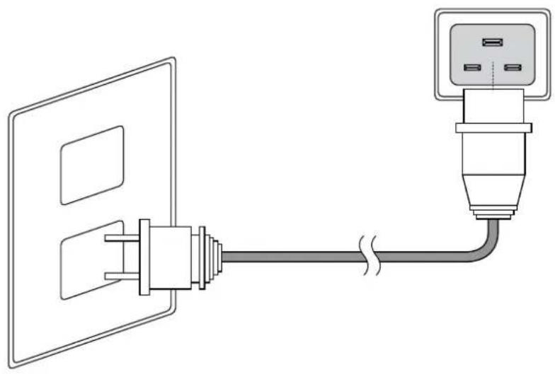
The D8800/D8900/D8010W ship with various types of AC power cords. Choose the one that is appropriate to your locale. Plug the female end of the power cord into the AC receptacle on the rear of the projector (AC 100V \~ 240V); Then, connect the other end to your AC power source.
natural_image
Diagram of a cable connection showing two connected components (no text or symbols)Press POWER SWITCH on the projector.
Press ON on remote control or POWER on the projector. The power LED indicator flashes green to indicate that it is warming up. When the projector is ready for use, the LED indicator turns off, and the projector lights.
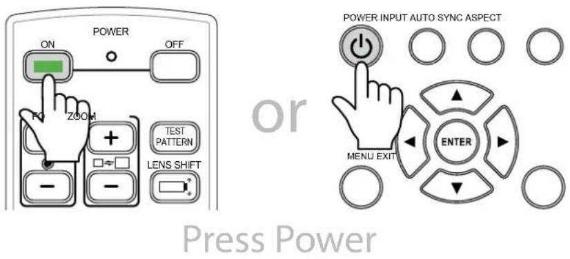
text_image
POWER ON OFF ZOOM TEST PATTERN LENS SHIFT - - Power INPUT AUTO SYNC ASPECT MENU EXIT ENTER Press Power


POWER LED
Flash Green clolor
CHANGING THE OSD LANGUAGE
The D8800/D8900/D8010W can display the menus in English, French, Spanish, German, Portuguese, Simplify Chinese, Traditional Chinese, Japanese or Korean. Press MENU to display the OSD, press ◀▶ to select CONTROL item. Then press ▲▼ to select LANGUAGE and press ▲▼ a language that you wanted. Then press ENTER to confirm your selection.
| INPUT | P | ICTURELAMPS ALIGNMENT | CONTROL | SERVICE | ||
| Language | Eco Network Power | < | Eco | > | ||
| English | Auto Power Off | < | On | > | ||
| Français | Auto Power On | < | Off | > | ||
| Español | Projector Control | < | ---- | > | ||
| Deutsch | Network | Enter | ||||
| Português | Start Up Logo | < | On | > | ||
| 简体中文 | Trigger | < | Auto | > | ||
| 繁體中文 | Auto Search | < | Off | > | ||
| 日本語 | Dynamic Black | < | On | > | ||
| 한국어 | Language | Enter | ||||
ADJUSTING THE PICTURE ORIENTATION
If the D8800/D8900/D8010W is installed behind the screen, you must change the picture orientation to match the installation method.
Refer to "Modes of installation" on page 15. To do this, press MENU on the remote control. Then select ALIGNMENT -> Projection Mode -> Rear.
If the projector is ceiling-mounted, the D8800/D8900/D8010W will automatically inverts the image. If this automatic inversion is not desired, please select Ceiling Mode from the Menu -> ALIGNMENT -> Projection Mode -> Ceiling + Front or Ceiling + Rear.
| INPUT | P | ICTURELAMPS | ALIGNMENT | CONTROL SERVICE | ||
| Projection Mode | < | Front | > | |||
| Fan Mode | < | Normal | > | |||
| Lens Control | Enter | |||||
| Lens Memory | Enter | |||||
| Center Lens | Execute | |||||
| Warp | Enter | |||||
| Blanking | Enter | |||||
| Edge Blend | Enter | |||||
LENS ADJUSTMENTS
The D8800/D8900/D8010W gives you a great deal of control over the picture size, position and focus. Focus To focus the projected image, grasp the lens by the front ring and rotate it.
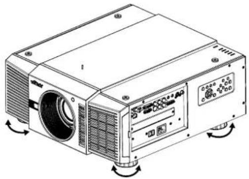
natural_image
Line drawing of a projector with visible fan and control panel (no text or symbols)Adjust foot
Rotate the 4 feet on projector for image position.
Note:
Ceiling Mode can't adjust this function.

text_image
LENS SHIFT Shift adjustmentVertical Lens Shift
To shift the projected image vertically, press ▲ ▼ on the keypad.
Range: Up, 50%; Down, 0%.
Horizontal Lens Shift
To shift the projected image horizontally, press ◀▶ on the keypad.
Range: Right, 10%; Left, 10%.
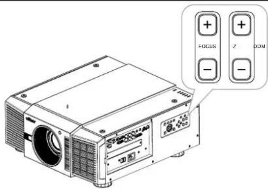
text_image
FOCUS Z ODMZoom
To make the picture smaller (zoom out) or larger (zoom in).
Press ZOOM on the keypad the appropriate direction.
Focus
To make the picture clear or Fuzzy.
To focus the current image, press FOCUS on the keypad appropriate direction.
SELECTING AN INPUT SOURCE
When you turn on the D8800/D8900/D8010W, it switches to the last selected input and looks for a valid signal. Press INPUT on the remote control to select an input source directly.
SELECTING AN ASPECT RATIO
Press ASPECT to adjust the video aspect ratio.

USING THE OSD
- Press the MENU button on the remote control or machine top cover's keypad to display the OSD main menu.
- Press ◀ or ▶ to select a sub-menu.
- Press ▲ or ▼ to select a sub-menu item.
- For each sub-menu item, the currently-selected value is highlighted. Press ▲ or ▼ to choose a setting for that item, and press ENTER on the remote controller or SELECT on the keypad to adjust the value of that item.
- If want return to the previous menu, please press MENU.
- In the Main Menu, press MENU to turn off the OSD menu. The D8800/D8900/D8010W OSD menus are arranged.
START USING THE PROJECTOR - OSD INTRODUCTION
OSD MENU TREE
| INPUT | Input Selection | HDMIDVIVGAComponent / BNCCompositeS-Video3G-SDI |
| PIP | PIP OptionPIP InputPIP SwapPosition | |
| Test Pattern | Color BarCrosshatchBurstResGreenBlueWhiteBlackUncorrected RedUncorrected GreenUncorrected BlueH RampOff | |
| Color Space | AutoYCbCrYPbPrRGB-PCRGB-Video | |
| Input Lock | Auto48Hz50Hz60Hz | |
| Background | LogoBlueBlackWhite | |
| Video Standard | AutoPALSECAMNTSC | |
| Auto Sync Adjust | OffAutoAlways |
| PICTURE | Display Mode | High Bright Presentation Video |
| Contrast | 0~200 | |
| Brightness | ||
| Adaptive Contrast | On Off | |
| Saturation | 0~200 | |
| Hue | ||
| Gamma | Film Graphics Video | |
| Color | Color Temperature Trim | |
| Sharpness | 0~200 | |
| Noise Reduction | ||
| Aspect Ratio | 5:44:316:1016:91.882.35Letterbox Native Unscaled | |
| Overscan | Off Crop Zoom | |
| VGA Setup | H Total H Start H Phase V Start | |
| Auto Sync Execute |
| LAMP | Mode | SingleDual |
| Power | EcoNormalCustom Power Level | |
| High Altitude | OnOff | |
| Custom Power Level 8 | 0.4%~100% | |
| Lamp 1 Status | On | |
| Lamp 2 Status | Off | |
| ALIGNMENT | Projection Mode | FrontRearCeiling + FrontCeiling + Rear |
| Fan Mode | NormalUpDown | |
| Lens Control | ZoomFocus | |
| Lens Memory | Load MemorySave Memory | |
| Center Lens Execute | ||
| Warp | KeystoneRotationPincushion / BarrelTop Left CornerTop Right CornerBottom Left CornerBottom Right CornerCustom WarpReset | |
| Blanking | TopBottomLeftRightReset | |
| Edge Blend | Edge BlendBlend WidthBlack Level UpliftReset |
| CONTROL | Eco Network Power | Standard Eco |
| Auto Power Off | On Off | |
| Auto Power On | ||
| Projector Control | RS232 Network | |
| Network | IP Address Subnet mask Gateway DHCP | |
| Start Up Logo | On Off | |
| Trigger | 5:4 4:3 16:10 16:9 1.88 2.35 Letterbox Native Unscaled Auto | |
| Auto Search | On Off | |
| Dynamic Black | ||
| Language | English Français Español Deutsch Português 簡体中文繁體中文日本語 한국어 |
| SERVICE | Model | |
| Serial Number | ||
| Software Version | ||
| Active/PIP Source | ||
| Pixel Clock | ||
| Signal Format | ||
| H/V Refresh Rate | ||
| Lamp 1 Time x HRS | ||
| Lamp 2 Time x HRS | ||
| Power On Time x HRS | ||
| Blue Only | On Off | |
| Factory Reset |
OSD INTRODUCTION - INPUT
| INPUT | PICTURE | LAMPS ALIGNMENT CONTROL SERVICE | |
| Input Selection | Enter | ||
| PIP | Enter | ||
| Test Pattern | Enter | ||
| Color Space | < | RGB-PC | > |
| Input Lock | < | Auto | > |
| Background | < | Logo | > |
| Video Standard | < | ---- | > |
| Auto Sync Adjust | < | Always | > |
—Input Selection
This function is same as the hotkey which on Remote controller. You can use remote controller or this function to select the correct input source. Refer to "Selecting An Input Source" on page 25.
— HDMI
HDMI input from PC or media device.
— DVI
DVI input from PC.
— VGA
Analog RGB from PC.
— Component / BNC
Analog / serial digital interface from media device.
— Composite
Traditional composite video from media device.
— S-Video
Super video (Y/C seperated).
3G-SDI
Uncompressed digital video from a serial connection (coaxial).
| Timing SDI Link mode Signal | Standards | Color Encode | Sampling Structure | Bit depth | Cable Length Tested | |
| NTSC | SD | SMPTE 259M-C 270Mbps SD | YCbCr | 4:2:2 | 10 | 128m |
| PAL | SD | SMPTE 259M-C 270Mbps SD | YCbCr | 4:2:2 | 10 | 128m |
| 1035i 60Hz | HD-Single | SMPTE 292M292M 1.5Gbps HD | YCbCr | 4:2:2 | 10 | 128m |
| 1080i 59.94Hz | HD-Single | SMPTE 292M292M 1.5Gbps HD | YCbCr | 4:2:2 | 10 | 128m |
| 1080i 60Hz | HD-Single | SMPTE 292M292M 1.5Gbps HD | YCbCr | 4:2:2 | 10 | 128m |
| 1080P 30Hz | HD-Single | SMPTE 292M292M 1.5Gbps HD | YCbCr | 4:2:2 | 10 | 128m |
| 1080P 25Hz | HD-Single | SMPTE 292M292M 1.5Gbps HD | YCbCr | 4:2:2 | 10 | 128m |
| 1080P 50Hz | HD-Single | SMPTE 292M292M 1.5Gbps HD | YCbCr | 4:2:2 | 10 | 128m |
| Timing SDI Link mode Signal | Standards | Color Encode | Sampling Structure | Bit depth | Cable Length Tested |
| 108oP 24Hz HD-Single SMPTE 292 | M292M 1.5Gbps HD YCbCr 4:2:2 10 128m | ||||
| 72oP 60Hz HD-Single SMPTE 292 | M292M 1.5Gbps HD YCbCr 4:2:2 10 128m | ||||
| 72oP 50Hz HD-Single SMPTE 292 | M292M 1.5Gbps HD YCbCr 4:2:2 10 128m | ||||
| 108oSf 25Hz HD-Single SMPTE 292 | M292M 1.5Gbps HD YCbCr 4:2:2 10 128m | ||||
| 108oSf 30Hz HD-Single SMPTE 292 | M292M 1.5Gbps HD YCbCr 4:2:2 10 128m | ||||
| 108oP 50Hz 3G Level A SMPTE 424 | M 3Gbps YCbCr 4:2:2 10 128m | ||||
| 108oP 59.94Hz | 3G Level A SMPTE 424M 3Gbps YCbCr 4:2:2 10 128m | ||||
| 108oP 60Hz | 3G Level A SMPTE 424M 3Gbps YCbCr 4:2:2 10 128m | ||||
| 108oP 50Hz 3G Level B SMPTE 424 | M 3Gbps YCbCr 4:2:2 10 128m | ||||
| 108oP 59.94Hz | 3G Level B SMPTE 424M 3Gbps YCbCr 4:2:2 10 128m | ||||
| 108oP 60Hz | 3G Level B SMPTE 424M 3Gbps YCbCr 4:2:2 10 128m |
Note:
Signals are not supplied for D8800/D8900/D8010W, if it is not in the table.
—PIP
You can use this function to display multiple windows each containing an image.
— PIP Option
Use this to turn the function On/Off.
— PIP Input
Use this to select the input.
— PIP Swap
Use this to exchange displayed images.
— Position
Use this to select the location of the PIP window (Top left, Top Right, Bottom Left, Bottom Right, or Split L-R).
Top Left
Location
Top Right

text_image
2 1
text_image
1 2Split L-R

text_image
1 2Bottom Left

text_image
2 1Bottom Right

text_image
1 2Select this to enter the display test function.
—Color Space
This function allows you to change component, composite, and RGB sources. You can select different color space for different color performance.
— The default setting, Auto, functions as follows:
HDMI: If the Auxiliary Video Information (AVI) infoframe contains color space and/or range data, the D8800/D8900/D8010W use that information. Otherwise, for RGB sources, the D8800/D8900/D8010W use the RGB-Video color space. For component SDTV and EDTV resolutions, REC601 is used. For other component video resolutions, REC709 is used.
RGB: If Hsync or Vsync signals are present, the D8800/D8900/D8010W use the RGB-PC color space. Otherwise, REC601 is used for SDTV and EDTV sources, and REC709 for all other sources.
Component: For SDTV and EDTV resolutions, the D8800/D8900/D8010W use the REC601 color space. For all other resolutions REC709 is used.
— In most cases, the Auto setting determines the correct color space to use. If it does not, you can force the D8800/D8900/D8010W to use a specific color space. Choose one of the following:
YCbCr uses component color space and sets black at 0,0,0 and white at 255,255,255.
YPbPr uses composite color space and sets black at o,o,o and white at 255,255,255.
RGB-PC uses RGB color space and sets black at o,o,o RGB and white at 255,255,255 RGB, assuming an 8-bit image.
RGB-Video uses RGB color space and sets black at 16,16,16 RGB and white at 235,235,235, assuming an 8-bit image, to correspond to the luminance values defined in digital component standards.
—Input Lock
Use this function to lock a source to an internal sync signal (Auto, 48Hz, 50Hz, or 60Hz). Auto setting locks the sync signal to the current source.
—Background
Use this function to specify the content or color to be displayed on the blank screen when no input signal is available. You can choose from Logo, Blue, Black, White. The default value is Logo.
—Video Standard
Different countries may use different video signal formats. Please choose the video standard in your area.
— Auto
The color systems are automatically identified and the format is set accordingly.
— PAL (Phase Alternation By Line)
This is the standard used in Europe, Australia and many other parts of the world, typically with a 50Hz frame rate.
— SECAM (Sequential Color With Memory)
This is a standard format used mainly in France and Russia. Gamma: Select Gamma from the ADVANCED menu to choose a DLP de-gamma curve. Used correctly, the Gamma control can improve contrast while maintaining good details for blacks and whites. If excess ambient light washes out the image and it becomes difficult or impossible to see details in dark areas, lower the gamma setting to compensate. This improves contrast while maintaining good details for blacks. Conversely, if the image is washed out and unnatural, with excessive detail in black areas, increase the setting.
— NTSC (National Television Systems Committee)
This is the standard format used mainly in the United States and Japan.
Note:
Generally speaking, the projector will be able to automatically detect the video standard used in your area. However, there are circumstance where the projector will fail to interpret the video standard used and the user will have to manually configure the video format. If you are unsure of the video standard used in your area, please contact a qualified personnel and inquire about the video standard used in your area.
—Auto Sync Adjust
Use this function to set the automatic adjust setting for the incoming signal by adjusting the black level, gain, and reference (Off, Auto, Always).
OSD INTRODUCTION - PICTURE
| INPUT | PICTURE | LAMPS ALIGNMENT CONTROL SERVICE | |
| Display Mode | < | Video | > |
| Contrast | < | 100 | > |
| Brightness | < | 50 | > |
| Adaptive Contrast | < | Off | > |
| Saturation | < | ---- | > |
| Hue | < | ---- | > |
| Gamma | < | Film | > |
| Color | Enter | ||
| Sharpness | < | 0 | > |
| Noise Reduction | < | 0 | > |
| Aspect Ratio | < | 16:10 | > |
| Overscan | < | Off | > |
| VGA Setup | Enter | ||
| Auto Sync | Execute | ||
—Display Mode
Use ◀▶ to select the display mode.
—Contrast
Use ◀▶ to adjust the contrast of the projected image.
Note:
Brightness and Contrast controls are interactive. The screen change to one may require a subtle change to the other in order to achieve the optimum setting.
—Brightness
Use ◀▶ to adjust the level of black in the image to increase or decrease image brightness.
—Adaptive Contrast
Use ◀▶ to adjust the light and dark aspects of the contrast curve.
—Saturation
Use ◀▶ to adjust the color saturation levels (higher the level the higher the saturation).
—Hue
Use ◀▶ to adjust the Hue level for true color reproduction (Video and S-Video for NTSC). Gamma
Different Gamma settings will affect viewers' perception of the image. For images that are darker, it is recommended that Gamma be set higher to yield better image quality in darker regions by sacrificing details in brighter areas. In contrast, when projecting brighter images, you can set the Gamma lower to give up details in the darker areas to make the brighter areas (i.e. clouds) more visible.
— Film set the gamma to 2.2.
— Graphics should only be used for computer presentations that require increased brightness at the cost of grayscale accuracy.
— Video is similar to Film gamma but differs in dark areas of the image to correspond to the function that video cameras use to create images.
—Color
Use ◀▶ to adjust the color temperature of the projected image.
—Sharpness
The adjustment of sharpness primarily changes the value of high frequency detail. Use ◀▶ to adjust it.
—Noise Reduction
Use ◀ to adjust the noise of the projected image. This function is suitable for the elimination of image noise from interleaving SD input. Generally speaking, reducing image noise will lower the value of high frequency detail and make the image appear more mellow.
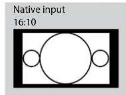
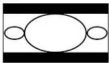
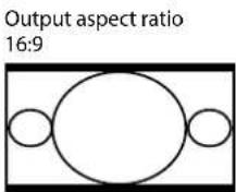
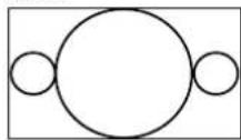
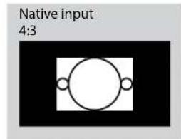
—Aspect Ratio
This function allow user adjust the picture's Aspect ratio.
When Native input is 16:10, the images as following is the result of picture's Aspect ratio for your reference.
text_image
Native input 16:10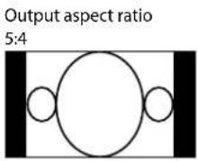
text_image
Output aspect ratio 5:4Output aspect ratio 2.35
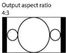
Output aspect ratio
Letterbox

Output aspect ratio Native

Output aspect ratio
Unscaled
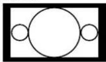
When Native input is 4:3, the images as following is the result of picture's Aspect ratio for your reference.
text_image
Native input 4:3Output aspect ratio 5:4

Output aspect ratio 2.35

Output aspect ratio 4:3

Output aspect ratio
Letterbox

Output aspect ratio 16:9
Output aspect ratio
Native
Output aspect ratio 1.88
Output aspect ratio
Unscaled

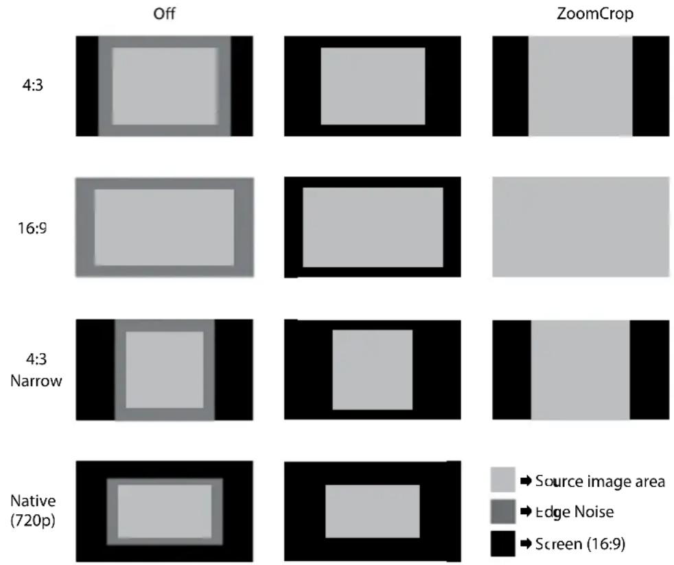
—Overscan
Some consumers may use the image that input source is not 16:9, and some programs may not display the edges of the image. Use this function to hide the image edge by choosing one of the following three options:
—VGA Setup
Use this function to set up the VGA display.
—Auto Sync
Use this function to set the automatic adjust setting for the incoming signal by adjusting the black level, gain, and reference (Off, Auto, Always).
OSD INTRODUCTION - LAMPS
| INPUT | P | ICTURELAMPS | ALIGNMENT CONTROL SERVICE | ||
| Mode | < | Single | > | ||
| Power | < | Eco | > | ||
| High Altitude | < | Off | > | ||
| Custom Power Level | < | ---- | > | ||
| Lamp 1 Status : | On | ||||
| Lamp 2 Status : | Off | ||||
—Mode
Use ◀▶ function to select single or dual lamp mode.
—Power
Use ◀ function to select Eco, normal, or custom power level.
—High Altitude
Use this function to control the projector's cooling fan. You can set it to Off or On. The default setting is Off.
Under normal circumstances, the projector will operate normally with this function set to Off. By default, the projector will detect the temperature of the surrounding environment to regulate the speed of the cooling fan. When the ambient temperature rises, fan speed will increase (generates louder noise) to make sure the heat inside the projector gets discharged and keep the projector working normally.
However, if you were to operate the projector in environment of excessive heat or in areas of high altitude, the projector may automatically shut down. When this happens, you can enable this function by setting it to On to force the cooling fan to work at a higher speed to regulate the temperature inside the projector.
Note:
High altitude region refers to area with elevation over 5000 feet.
—Custom Power Level
Use ◀▶ function to select a custom power level (80.4% to 100%).
—Lamp 1 Status
Use ◀▶ function to set lamp status to On/Off.
—Lamp 2 Status
Use ◀▶ function to set lamp status to On/Off.
OSD INTRODUCTION - ALIGNMENT
| INPUT | P | ICTURELAMPS | ALIGNMENT | CONTROL SERVICE | ||
| Projection Mode | < | Front | > | |||
| Fan Mode | < | Normal | > | |||
| Lens Control | Enter | |||||
| Lens Memory | Enter | |||||
| Center Lens | Execute | |||||
| Warp | Enter | |||||
| Blanking | Enter | |||||
| Edge Blend | Enter | |||||
—Projection Mode
Use ◀▶ function to select the projection mode (Front, Rear, Ceiling + Front, Ceiling + Rear).
—Fan Mode
Use ◀ function to set the fan mode (Normal, Up, Down).
—Lens Control
Use this function to set the lens control mode (Zoom/Focus).
—Lens Memory
Load Memory: Select this item to load the your own setting.
Save setting: You can adjust the OSD's items by yourself then use this function to save your setting.
—Center Lens
Use this to center the lens.
—Warp
Use this to correct image distortion.
— Keystone
Press ◀▶ to correct horizontal keystone due to projection angle. Press ▲▼ to correct Vertical keystone due to projection angle.
Rotation
Press ◀▶ to correct incorrect image angle.
Press ◀ to adjust angle to correct.

text_image
P
text_image
PPress ▶ to adjust angle to correct.

text_image
P— Pincushion / Barrel
Press ◀▶ to correct pincushion/barrel distortion.

text_image
PPress ◀▶ to correct pincushion distortion to correct image.

text_image
PPress ◀▶ to correct barrel distortion to correct image.

text_image
P
text_image
P— Top Left Corner
Press ◀▶ to correct top left corner image distortion.

text_image
PPress ◀▶ to correct top left corner image distortion to correct image.

text_image
P— Top Right Corner
Press ◀▶ to correct the right corner image distortion.

text_image
PPress ◀▶ to correct top right corner image distortion to correct image.

text_image
P— Bottom Left Corner
Press ◀▶ to correct the bottom left image distortion.

text_image
PPress ◀▶ to correct bottom left corner image distortion to correct image.

text_image
P— Bottom Right Corner
Press ◀▶ to correct the bottom left image distortion.

text_image
PPress ◀▶ to correct bottom right corner image distortion to correct image.

text_image
PCustom Warp
Use this to create custom warp values.
— Reset
Set all values to factory defaults.
—Blanking
Use this function to adjust the edges of the image and hide unwanted sections of the screen.
—TOP
Press ◀▶ on the remote control to adjust the top blanking area on the projected image.
—Bottom
Press ◀▶ on the remote control to adjust the bottom blanking area on the projected image.
—Left
Press ◀▶ on the remote control to adjust the left blanking area on the projected image.
—Right
Press ◀▶ on the remote control to adjust the right blanking area on the projected image.
—Reset
It will reset all the blanking functions to the default settings that is without any blanking functions enabled.
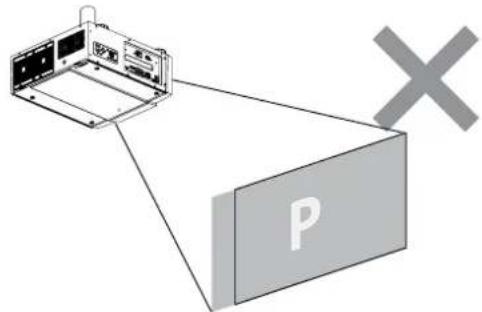
text_image
Diagram showing a device with labeled components and a 'X' symbol pointing to a box labeled 'P'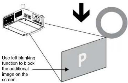
text_image
Use left blanking function to block the additional image on the screen. P—Edge Blend
Edge blend function requires multiple projectors simultaneously displaying on the same screen. Use this to adjust the uniformity of the images.
To use this function, Edge Blend must be enabled on both projectors.
— Edge Blend
- Press Menu to activate menu.
- Press ◀▶ to select Alignment and press Enter.
- Press ◀▶ to select Edge Blend and press Enter.
Note:
Notice that red and green lines appear to indicate the edge of the screen. The green lines indicate the start/end of the blend zone.
— Blend Width
The menu White Level allows for Top, Bottom, Left, and Right adjustment of a blending zone.
- Press Menu to activate menu.
- Press ◀▶ to select Alignment and press Enter.
- Press ◀▶ to select Edge Blend and press Enter.
- Press ◀▶ to select Blend Width and press Enter.
- Select an adjustment zone and use ◀▶ to correct the blend zone.
White Level
| Top | ◀ | 0 | ▶ |
| Bottom | ◀ | 0 | ▶ |
| Left | ◀ | 0 | ▶ |
| Right | ◀ | 0 | ▶ |
— Black Level Uplift
Black Level Uplift is used to compensate for the lack of pure black output from projectors, due to light leaking to the projection screen. When projecting black, the hot area where the two images overlap project twice the projectors' black output levels.
The solution is to adjust the Black Level Uplift. First make sure that the units connected to the projectors are outputting black. Then increase the Black Level Uplift (Top, Bottom, Left, Right) until the non-overlap area's brightness matches the overlap area.
To adjust Black Level Uplift
- Press Menu to activate menu
- Press ◀▶ to select Alignment and press Enter.
- Press ◀▶ to select Edge Blend and press Enter.
-
Press ◀▶ to select Black Level Uplift and press Enter.
-
Adjust the black level in zone A by setting the Selected Area (Top, Bottom, Left, Right) to match the black levels in zones B and C. You can also use Adjust (All, Red, Green, Blue) to set all primary colors.
Note:
— Four corners, black level uplift adjustment function is not available.
— Corner blending, black level uplift adjustment function is not available.
Black Level Uplift
| Select Area | |
| Top | 0 ▶ |
| Bottom | 0 ▶ |
| Left | 0 ▶ |
| Right | 0 ▶ |
| Adjust | |
| All | 0 ▶ |
| Red | 0 ▶ |
| Gerrn | 0 ▶ |
| Blue | 0 ▶ |
— Reset
This function sets Edge Blend figures to the factory default settings.
— Align Pattern
Enable this function to use a test pattern to align and adjust multiple images.
To use the Align Pattern:
- Setup two projects on a horizontal position and display the test grid pattern image on each.
- Create an overlap zone with the two test patterns by using the ▲▼◀▶ buttons on the remote control.

natural_image
Two grayscale grid panels with a right-pointing arrow, no text or symbols presentNote:
— Blanking and Blend combinations are specific to each model.
— Do not adjust black levels in order to use the Edge blend / four corner combination function.
— Do not adjust black levels in order to use the blend along corners function.
OSD INTRODUCTION - CONTROL
| INPUT | P | ICTURELAMPS ALIGNMENT | CONTROL | SERVICE |
| Eco Network Power | < Eco > | |||
| Auto Power Off | < On > | |||
| Auto Power On | < Off > | |||
| Projector Control | < ---- > | |||
| Network | Enter | |||
| Start Up Logo | < On > | |||
| Trigger | < Auto > | |||
| Auto Search | < Off > | |||
| Dynamic Black | < On > | |||
| Language | Enter |
—Eco Network Power
Use ◀ function to set Standard or Eco network power.
Auto Power Off
The default value is OFF. If you set it to ON, the projector will automatically shut down after 20 minutes without input signal.
Auto Power On
The default value is Off. If you set it to ON, the projector will automatically start up when it is connected to AC power. If you plug the projector's power cord into an AC socket with a switch, you can use this function to start up the projector using the socket's switch instead of the remote. If you do not need this function, please set it to Off.
—Projector Control
Use ◀ function to select RS232 or Network for the projector control.
—Network
Use this function to setup the network configuration.
To connect to a network (LAN), refer to the following steps:
- Connect an RJ45 cable to LAN ports on the projector and a router or hub on the network.
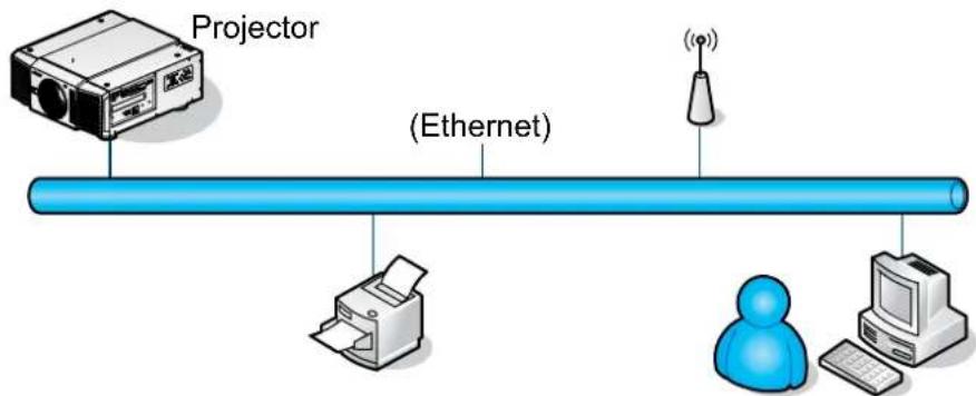
flowchart
graph LR
    A["Projector"] --> B["(Ethernet)"]
    B --> C["Printer"]
    C --> D["User"]
    D --> E["Computer"]
    style A fill:#f9f,stroke:#333
    style B fill:#ccf,stroke:#333
    style C fill:#cfc,stroke:#333
    style D fill:#fcc,stroke:#333
    style E fill:#cff,stroke:#333
- On the control PC, open a web browser and enter the IP address of the projector.
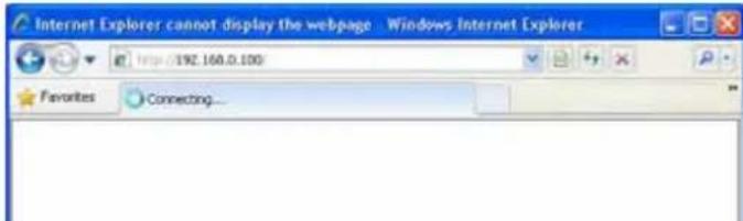
text_image
Internet Explorer cannot display the webpage - Windows Internet Explorer Http://192.160.0.100 Favorites Connecting...The Projector Web Server home page displays. In the example, the projector resides at IP address 192.168.0.100.
text_image
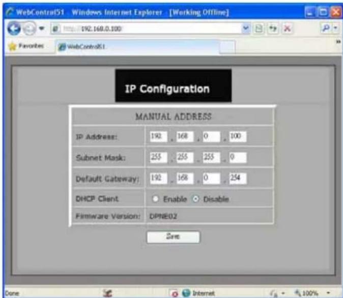
IP Configuration MANUAL ADDRESS IP Address: 192 168 0 100 Subnet Mask: 255 255 255 0 Default Gateway: 192 168 0 254 DHCP Client ○ Enable ○ Disable Firmware Version: DPNE02 Save- Make any desired changes to projector settings, then Click Save.
text_image
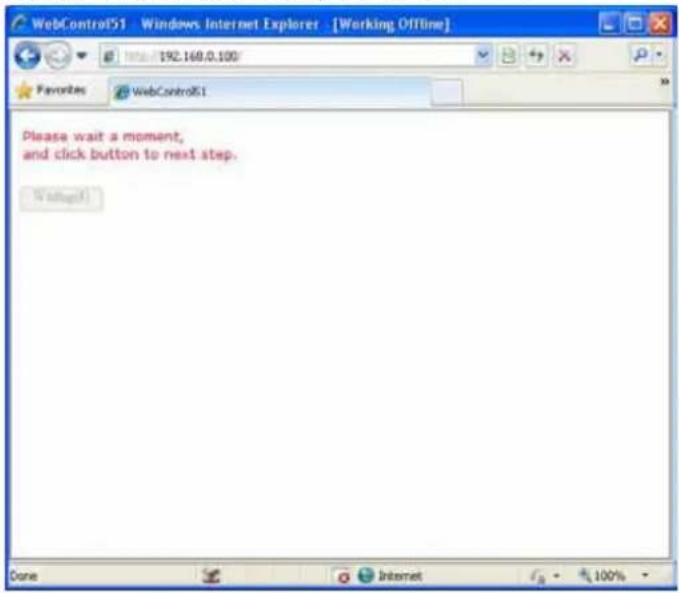
WebControl51 - Windows Internet Explorer - [Working OffLine] http://192.168.0.100/ Favorites WebControl51 Please wait a moment, and click button to next step. WaitcallTo connect to a stand alone PC or notebook, refer to the following steps:
- Connect an RJ45 cable to LAN ports on the projector and the PC (Laptop).
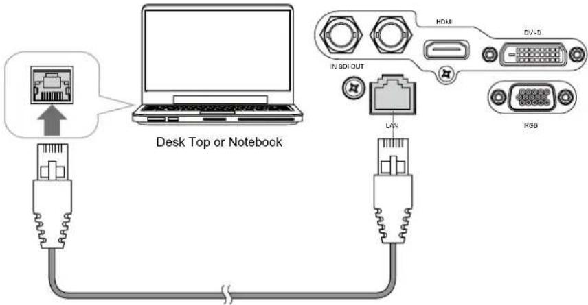
text_image
Desk Top or Notebook HDMI In SDI OUT LIV DV-5 HSB- On the PC (Laptop), select Start -> Control Panel -> Network Connections.
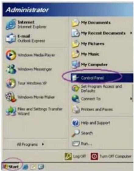
text_image
Administrator Internet Internet Explorer E-mail Outlook Express Windows Media Player Windows Messenger Tour Windows XP Windows Movie Maker Files and Settings Transfer Wizard All Programs My Documents My Recent Documents My Pictures My Music My Computer Control Panel Set Program Access and Defaults Connect To Printers and Fares Help and Support Search Run... Log Off Turn Off Computer Start- Right-click on Local Area Connection, and select Properties.

text_image
Network Connections File Edit View Favorites Tools Advanced Help Address Network Connectors LAN or High-Speed Internet Local Area Connections Connected, Firewallled Readout NetChrome Plus. On Wizard New Connection Wizard Disable Status Repair Bridge Connections Create Shortcut Delete Rename Properties View or change settings for the connection, such as adapter, protocol, or mode configuration settings.-
In the Properties window, select the General tab, and select Internet Protocol (TCP/IP).
-
Click Properties.

text_image
Local Area Connection Properties General | Advanced | Connect using: Broadcom Net0-xtreme 57xx Gigabit Cc Configure... This connection uses the following items: QoS Packet Scheduler Network Monitor Driver Internet Protocol [TCP/IP] Install... Uninstall... Properties Description Transmission Control Protocol/Internet Protocol. The default wide area network protocol that provides communication across diverse interconnected networks. Show icon in notification area when connected Notify ge when this connection has limited or no connectivity OK Cancel-
Click Use the following IP address.
-
Fill in the IP address and subnet mask. Make sure the IP address of the projector and PC are in the same network group. For example, 192.168.o.X. Whereas X must contain a different value. Then click OK.

text_image
Internet Protocol (TCP/IP) Properties General You can get IP settings assigned automatically if your network supports this capability. Otherwise, you need to ask your network administrator for the appropriate IP settings. Obtain an IP address automatically Use the following IP address: IP address: 192 168 0 99 Subnet mask: 255 255 255 0 Default gateway Optimize DNS server addresses automatically Use the following DNS server addresses: Preferred DNS server: Alternate DNS server: Advanced... OK Cancel- On the control PC, open a web browser and enter the IP address of the projector.

text_image
Internet Explorer cannot display the webpage - Windows Internet Explorer http://192.168.0.100 Favorites Connecting...The Projector Web Server home page displays. In the example, the projector resides at IP address 192.168.0.100.

text_image
WebControl51 - Windows Internet Explorer - [Working Offline] Families WebControl51 IP Configuration MANUAL ADDRESS IP Address: 192 168 0 100 Subnet Mask: 255 255 255 0 Default Gateway: 192 168 0 254 DHCP Client Enable Disable Firmware Version: OPNE02 Zins Done Internet- Make any desired changes to projector settings, then Click Save.

text_image
Please wait a moment, and click button to next step. Refreshed- Access Tera Term tool.

text_image
Term Term: New connection TCP/IP Host: 192.168.0.100 Service: ○ Telnet ○ SSH SSH version: SSH2 ○ Other Protocol: UNSPEC ○ Serial Past: COM3: Intel(R) Active Management Te OK Cancel HelpUse RS-232 command to control the Projector.
—Start Up Logo
Use ◀ function to turn On/Off the start up logo.
—Trigger
The projector comes with one set of Trigger output. You can configure one devices connected to the projector via the trigger port to be automatically turned on when the projector is on. There will be a 2-3 second delay prior to activation to prevent operation of this function when the user is choosing the desired aspect ratio.
— 5:4: Outputs 12V of power on Trigger when chooses the 5:4 aspect ratio.
— 4:3: Outputs 12V of power on Trigger when chooses the 4:3 aspect ratio.
— 16:10: Outputs 12V of power on Trigger when chooses the 16:10 aspect ratio.
— 16:9: Outputs 12V of power on Trigger when chooses the 16:9 aspect ratio.
— 1.88: Outputs 12V of power on Trigger when chooses the 1.88 aspect ratio.
— 2.35: Outputs 12V of power on Trigger when chooses the 2.35 aspect ratio.
— Letterbox: Outputs 12V of power on Trigger when chooses the Letterbox aspect ratio.
— Native: Outputs 12V of power on Trigger when chooses the Native aspect ratio.
— Unscaled: Outputs 12V of power on Trigger when chooses the Unscaled aspect ratio.
— Auto: Outputs 12V of power on Trigger automatically.
—Auto Search
Use ◀ function to turn On/Off auto search.
—Dynamic Black
Use ◀▶ function to turn On/Off dynamic black.
—Language
Choose the OSD display language that you familiar. English, French, Spanish, Dutch, Portuguese, Simplify Chinese, Traditional Chinese, Japanese or Korean.
OSD INTRODUCTION - SERVICE
| INPUT | P | ICTURELAMPS ALIGNMENT CONTROL | SERVICE | |
| Model : | DP9675QDPxA | |||
| Serial Number : | C202XXXX00767 | |||
| Software Version : | MD05-GD02-Ub01- 9999-31-DPNE02-D02 | |||
| Active/PIP Source : | HDMI / Off | |||
| Pixel Clock : | 83 .30 MHZ | |||
| Signal Format : | 1280x800@60Hz | |||
| H/V Refresh Rate : | H: 49.578 KHZ V: 60 HZ | |||
| Lamp 1 Time : | 7 HRS | |||
| Lamp 2 Time : | 7 HRS | |||
| Power On Time : | 7 HRS | |||
| Blue Only | < Off > | |||
| Factory Reset | Enter | |||
The functions covered in this unit relate to the display of some basic information about the projector.
Note:
Memory of the custom timing files will be erased in the Factory Reset operation.
—Model
The designated model number of the projector.
—Serial Number
The designated serial number of the projector.
—Software Version
The version of software installed on the projector.
—Active/PIP Source
Displays the current Active/PIP sources.
—Pixel Clock
Displays the pixel clock of the current input signal.
—Signal Format
Displays the format of the current input signal.
—H/V Refresh Rate
Displays the horizontal and vertical refresh rates for the current image.
—Lamp 1 Time
Display the lamp 1 usage time. When you change the new lamp. The lamp hours will re-calculate the time.
—Lamp 2 Time
Display the lamp 2 usage time. When you change the new lamp. The lamp hours will re-calculate the time.
—Power On Time
Display the total On time for projector. Display only.
—Blue Only
Enabling this option will make the projector display only blue color to facilitate the process of image inspection for the service personnel. For detailed instructions on how to use this function, consult a qualified service personnel.
—Factory Reset
Use this function to restore the configurations in the OSD Menu back to factory default. Note that this function will not apply to items including no signal, network, Projector control, startup Logo, language, High Altitude mode and lamp hours.
Note:
When Factory Reset is executed, all source memories created by the projector (i.e. timings files) will be erased.
CHANGE LAMP
The lifecycle of ordinary projection lamp typically lasts for 1200 hours before requiring replacement (different lamp configurations will affect lamp life). From the OSD Menu, you can go to "OSD Introduction - SERVICE" on page 45 to check how long a lamp has been used. You should also replace the lamp when the projected image gets noticeably darker. Contact your local dealer to purchase new certified lamps for your projector.
TO REPLACE THE PROJECTOR LAMP1
- Turn off the projector and unplug the power cord. Let the projector cool for approximately 60 minutes before removing the lamp module for replacement.
Note:
When you turn off the projector, the lamp inside the projector will still be very hot (approximately 200 \~ 300°C). If you attempt to replace the lamp without allowing the projector to cool, you could risk scalding yourself. This is why you should wait for no less than 60 minutes for the lamp to cool down in order to perform the replacement safely.
- Loosen the fan.

natural_image
Technical line drawing of an electronic device with cooling fans and a drive unit (no text or symbols)- Use a screw driver to loosen the screws as shown in the illustration and pull the lamp out.

natural_image
Technical line drawing of a modular industrial machine with cooling unit and mounting base (no text or symbols)- Insert the new lamp in the direction shown in the illustration into the lamp assembly; tighten the three screws using a screw diver and make sure the lamp is firmly secured to prevent the lamp from shaking or poor contact.
natural_image
Technical line drawing of an industrial machine with cooling unit and fan components (no text or symbols)- Replace the fan and firmly secure the one screw on the fan.
natural_image
Technical line drawing of an electronic device with cooling fans and a central fan (no text or symbols)TO REPLACE THE PROJECTOR LAMP2
- Loosen the fan.
- Use a screw driver to loosen the screws as shown in the illustration and pull the lamp out.
- Insert the new lamp in the direction shown in the illustration into the lamp assembly; tighten the three screws using a screw diver and make sure the lamp is firmly secured to prevent the lamp from shaking or poor contact.
- Replace the fan and firmly secure the one screw on the fan.
natural_image
Technical line drawing of an industrial machine with cooling fan and ventilation unit (no text or symbols)
natural_image
Technical line drawing of an industrial electronic device with cooling fans and a central unit (no text or symbols)
natural_image
Technical line drawing of an industrial machine with cooling fans and heat exchangers (no text or symbols)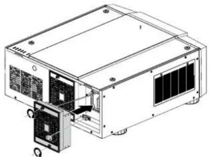
natural_image
Technical line drawing of an electronic device with cooling fan and ventilation slots (no text or symbols)CHANGE LENS
TO REPLACE THE PROJECTOR LENS
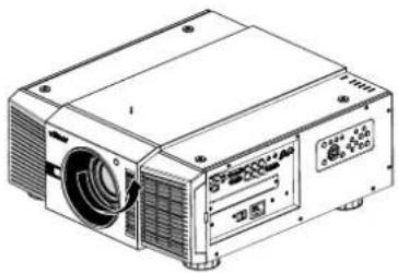
- Remove the front cover.
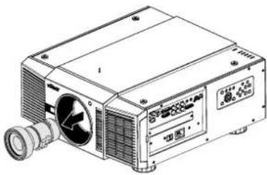
- Press and hold the lens lock button. Support the lens with one hand and turn clockwise loose the lens.
natural_image
Line drawing of a projector device with control panel and display (no text or symbols)- Pull the lens backward and slide the lens out of the lens holder.
natural_image
Technical line drawing of a projector unit with fan and control panel (no text or symbols)- Insert the lens that female jock is in front of the male jack (upper left corner). Ensure the lens touches the lens holder.

natural_image
Technical line drawing of a projector device with fan and control panel (no text or symbols)- Secure the lens in the lens holder by turning counterclockwise the lens to the "locked" position.

natural_image
Line drawing of a projector unit with control panel and fan (no text or symbols)- Check if the lens is really secured by trying to pull the lens out of the lens holder.
Six models of lens for D88oo(WUXGA)
| Vivitek Part Number Lens F# TR Zoom Ratio | ||||
| D88-ST001 Standard Lens 1.7 ~ 1.9 1.73 ~ 2.27 | 1.3 | |||
| D88-WF18501 | Wide Fix | 1.85 | 0.79 | N/A |
| D88-WZ01 | Wide Zoom | 1.85 ~ 2.50 | 1.25 ~ 1.79 | 1.41 |
| D88-SMLZ01 | Semi Long Zoom 1 | 1.86 ~ 2.48 | 2.22 ~ 3.67 | 1.65 |
| D88-LOZ101 | Long Zoom 1 | 1.85 ~ 2.41 | 3.58 ~ 5.38 | 1.5 |
| D88-LOZ201 | Long Zoom 2 | 1.85 ~ 2.48 | 5.31 ~ 8.26 | 1.55 |
■ Six models of lens for D8900(XGA)
| Vivitek Part Number Lens F# TR Zoom Ratio | ||||
| D88-ST001 Standard Lens 1.7 ~ 1.9 1.79 ~ 2.35 1.3 | ||||
| D88-WF18501 Wide Fix 1.85 0.8 N/A | ||||
| D88-WZ01 | Wide Zoom | 1.85 ~ 2.50 | 1.3 ~ 1.85 | 1.41 |
| D88-SMLZ01 | Semi Long Zoom | 1.86 ~ 2.48 | 2.3 ~ 3.81 | 1.65 |
| D88-LOZ101 | Long Zoom1 | 1.85 ~ 2.41 | 3.67 ~ 5.64 | 1.5 |
| D88-LOZ201 | Long Zoom2 | 1.85 ~ 2.48 | 5.5 ~ 8.56 | 1.55 |
■ Six models of lens for D8010W(WXGA)
| Vivitek Part Number Lens F# TR Zoom Ratio | ||||
| D88-ST001 Standard Lens 1.7 ~ 1.9 | 1.80 ~ 2.38 | 1.3 | ||
| D88-WF18501 | Wide Fix | 1.85 | 0.76 | N/A |
| D88-WZ01 | Wide Zoom | 1.85 ~ 2.50 | 1.31 ~ 1.87 | 1.41 |
| D88-SMLZ01 | Semi Long Zoom | 1.86 ~ 2.48 | 2.33 ~ 3.86 | 1.65 |
| D88-LOZ101 | Long Zoom1 | 1.85 ~ 2.41 | 3.71 ~ 5.57 | 1.5 |
| D88-LOZ201 | Long Zoom2 | 1.85 ~ 2.48 | 5.56 ~ 8.67 | 1.55 |
CHANGE FILTER
The filter should be changed every 3000 hours.
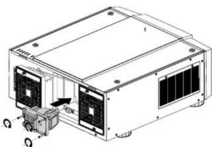
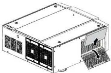
TO REPLACE THE FILTER ON THE LEFT SIDE OF THE PROJECTOR
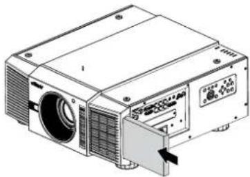
- Remove the cover on the left side of the projector.

natural_image
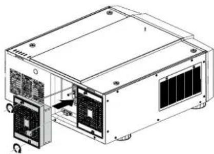
Line drawing of a projector device with ventilation slots and control panel (no text or symbols)- Remove the filter from it.

natural_image
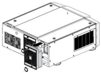
Technical line drawing of a projector unit with ventilation slots and an open lid (no text or symbols)- Insert a new filter.
natural_image
Technical line drawing of a projector with ventilation slots and a control panel (no text or symbols)- Install the cover on the left side of the projector.

natural_image
Line drawing of a projector device with ventilation slots and control panel (no text or symbols)TO REPLACE THE FILTER ON THE RIGHT SIDE OF THE PROJECTOR
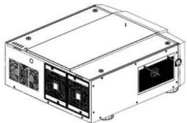
- Loosen the fan cover on the right side of the projector.
natural_image
Technical line drawing of a rectangular electronic device with multiple ports and mounting holes (no text or symbols)- Open the fan cover and remove the filter from it.
natural_image
Technical line drawing of a computer power supply unit with cooling fans and ventilation slots (no text or symbols)- Insert a new filter and install the fan cover on the right side of the projector.

natural_image
Illustration of a computer power supply unit with cooling fans and a monitor (no text or symbols visible)- Secure the fan cover.

natural_image
Technical line drawing of a rectangular electronic device with multiple ports and mounting holes (no text or symbols)■ Optional component
| Component P/N | |
| Handle D88-Acc-HDL-oo | |
| Foot D88-Acc-Fot-oo | |
| Filter D88-AFoo |
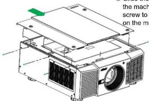
Change the Color Wheel
The color wheel is on the top side.

natural_image
Technical line drawing of two electronic device rear panels with green connectors and ports (no text or symbols)① Loosen the top cover Slide the cover and remove it.

text_image
② Loo② Loosen the color wheel's screw.

text_image
④ Repla- that yo④ Replace the color wheel that you wanted.

text_image
③ Life up③ Life up the color Wheel

text_image
Technical diagram showing internal components of a device with labeled parts and an inset view highlighting internal structure.⑤ Tighten the screws.
text_image
the mach screw to on the ma⑥ Slide the bracket to recover the machine then use the screw to fix the top bracket on the machine.
LED STATUS
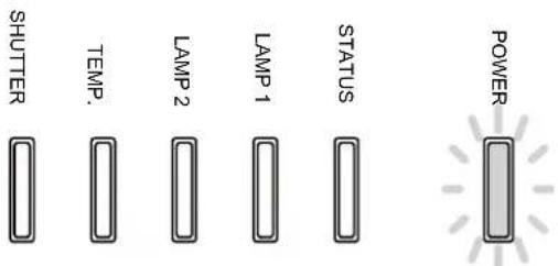
text_image
SHUTTER TEMP. LAMP 2 LAMP 1 STATUS POWERPOWER LED
| LED Display Projector status Procedure | |||
| Off Power is off | |||
| Flashing Green Pre | pare to turn on projector Wait till projector start displaying | ||
| Orange Projector cooling Wait until cooling finish (~90 sec) | |||
| On Red Standby mode | |||
STATUS LED
| LED Display Projector status Procedure | |||
| Off No Problem | |||
| Flashing Red (Cycles of 1) Cover Problem | Contact local Vivitek Server Center | ||
| On Red System Error | Contact local Vivitek Server Center | ||
LAMP1/LAMP2 LED
| LED Display Projector status Procedure | |||
| Off Lamp off | |||
| Flashing Green Prep | are to light lamp | ||
| Red (Cycles of 6) | Lamp lit fail | ||
| On Red Lamp is end-of-life | |||
TEMP LED
| LED Display Projector status Procedure | |||
| Off No Problem | |||
| Flashing | Red | Temperature problem | Contact local Vivitek Server Center |
SHUTTER LED
| LED Display Projector status Procedure | |
| Off Shutter is open | |
| Flashing Green Shutter is closed |
SPECIFICATIONS
| Model D8800 D8900 D8010W | ||||
| Display Type DLP | ||||
| Brightness 8000 ANS Lumens | 10,000 ANS Lumens 8000 AN$ Lumens | |||
| Native Resolution WUXGA (1920 x 1200) XGA (1024 x 768) WXGA (1280 x 800) | ||||
| Maximum Resolution | WUXGA (1920 x 1200)@60Hz | |||
| Contrast Ratio | 3000:1 | |||
| Lamp Life and Type | 2000/2500 Hours (Std. / Eco Mode), 400W x 2 | |||
| Throw Ratio (Standard Lens) | 1.73 - 2.27:1 | 1.79-2.35:1 1.81-2.38:1 | ||
| Image Size (Diagonal) | 40"-500" | 40"-500" | 40"-500" | |
| Projection Distance | 1.83 - 14.9m (6 - 49ft) | 1.79 - 14.54m (5.87 - 47.07ft) | 1.93 - 15.64m (6.3 - 51.31ft) | |
| Projection Lens | F = 1.7 - 1.9f = 25.7 - 33.7mm | |||
| Zoom Ratio (Standard Lens) | 1.3X | |||
| Aspect Ratio | 16.10 Native, 4.3 and 16:9 Compatible | |||
| Offset | 0% ~ +50% | |||
| Keystone Correction | Vertical: +/-30°Horizontal: +/-35° | |||
| Synchronization | Vertical: 48 - 120 HzHorizontal: 15 - 108kHz | |||
| Edge Blending | Yes (built-in) | |||
| Lens Shift Range | Vertical: +/- 50%Horizontal: +/- 10% | |||
| Video Compatibility | SDTV(480i/576i), EDTV (480p/576p), HDTV (720p, 1080i/p), NTSC/NTSC 4.43, PAL B/G/H/I/M/N 60, SECAM | |||
| I/O Connection Ports | HDMI v1.3, DVI-D, Component (YPbPr), VGA-In (x2), S-Video, Composite, 3G HDSDI-In, 3GHDSDI-Out, RJ45, 12V Trigger, RS-232C, Wired Remote | |||
| Projection Method | Table Top, Ceiling Mount (Front or Rear) | |||
| Dimensions (W x D x W) | 508 x 552.6 x 229mm (20" x 21.8" x 9") | |||
| Weight (Without Lens) | 24kg (52.9lbs) | |||
| Noise Level | 39 dB/39 dB (Single Lamp Eco./Std Mode)39 dB/43 dB (Dual Lamp Eco./Std Mode) | |||
| Power Supply | AC 100-240V, 50/60Hz | |||
| Power Consumption | Lamp Style | Dual Lamp | Single Lamp | |
| 220V | 960W 450W | |||
| 110V | 995W 440W | |||
| Standby: 0.5W (Without RJ-45, RS-232 Enabled) | ||||
| Standard Accessories | AC Power CordVGA CableRemote ControlLens CapDocumentation Kit | |||
| Optional Accessories | Replacement LampRemoteCarry HandleFoot SocketInterchangeable Lens Options (x6) | |||
SERIAL INTERFACE SPECIFICATIONS
TRANSFER SPECIFICATIONS
| Item Specifications | |
| Transmission Speed 38400 bps | |
| Data Length 8 bit | |
| Parity None | |
| Stop Bit 1 | |
| Flow Control None |
RS-232 COMMANDS
There are 2 types of commands:
—Key commands
—Operation commands
All commands start with 2 letters as shown in the following:
—“ky” for key commands.
—“op” for operations commands.
— Key Commands The following example is the syntax for key commands: ky
IR Codes and Key Names
| Key | Code | RS232 Key name | Key Wording | Description |
| 1 | ox90 | ON | Turn power on. | |
| 2 | ox91 | OFF | Turn power off. | |
| 3 | oxB6 | FOCUS+ | ||
| 4 | oxB7 | ZOOM+ | Zoom in. | |
| 5 | oxB8 | TEST PATTERN | Enter test pattern menu. | |
| 6 | oxB9 | FOCUS- | ||
| 7 | oxBA | ZOOM- | Zoom out. | |
| 8 | oxBB | LENS SHIFT | Shift control of the lens. | |
| 9 | oxC1 | ▲ | Keypad up arrow. | |
| 10 | oxC3 | ◀ | Keypad left arrow. | |
| 11 | oxC4 | ▶ | Keypad right arrow. | |
| 12 | oxC5 | ENTER | Keypad enter. | |
| 13 | oxC2 | ▼ | Keypad down arrow. | |
| 14 | ox87 | MENU | Show or hide the OSD menu. | |
| 15 | oxBC | EXIT | Exit the OSD menu. | |
| 16 | ox83 | INPUT | Switch the active source. | |
| 17 | ox98 | PICTURE | Open PICTURE menu. | |
| 18 | ox8C | NETWORK | ||
| 19 | ox86 | AUTO SYNC | ||
| 20 | ox9F | ASPECT | Switch to the next aspect ratio. | |
| 21 | ox8F | PIP | ||
| 22 | oxBD | OVERSCAN | ||
| 23 | ox8E | FREEZE | ||
| 24 | ox8b | LAMP MODE | ||
| 25 | oxBE | 3D MODE | Not available. | |
| 26 | oxBF | INFO | Open SERVICE menu. | |
| 27 ox9E LIGHT | ||||
| 28 ox9A CLEAR | Not available. | |||
| 29 ox9B SHUTTER Turn on or off the shutter. | ||||
| 30 ox9C ID SET | Not available. | |||
OPERATIONS COMMANDS
The following example is the syntax for operations commands: op
| No. | Function | Command | Action on unit |
| 1 | Set | = | Makes the unit take that value. |
| 2 | Get | ? | Asks what the current value is. |
| 3 | Increment | + | Adds 1 to the current value. |
| 4 | Decrement | - | Subtracts 1 from the current value. |
| 5 | Execute | (none) | Performs an action. |
| Operation | Command | Values |
| 1. INPUT | ||
| input.sel | = ? | 0 = HDMI1 = DVI2 = VGA3 = Component / BNC4 = Composite5 = S-Video6 = 3G-SDI7 = Option Board (Reserved) |
| pip | = ? | 0 = Off1 = On |
| pip.sel | = ? | 1 = HDMI2 = DVI3 = VGA4 = Component / BNC5 = Composite6 = S-Video7 = 3G-SDI8 = Option Board (Reserved) |
| pip.swap | (execute) | Swap main and PIP source |
| pip.pos | = ? | 0 = Top Left1 = Top Right2 = Bottom Left3 = Bottom Right4 = Split L-R |
| pattern | = ? | 0 = Color Bar1 = Cross Hatch2 = Burst3 = Red4 = Green5 = Blue6 = White7 = Black8 = Red (TI)9 = Green (TI)10 = Blue (TI)11 = HRamp (TI)12 = Off |
| Operation Command Values | ||
| color.space = ? o = Auto | 1 = YCbCr2 = YPbPr3 = RGB-PC (0-255)4 = RGB-Video (16-235) | |
| input.lock = ? o = Auto | 1 = 48 Hz2 = 50 Hz3 = 60 Hz | |
| no.signal = ? o = Logo | 1 = Blue2 = Black3 = White | |
| vid.std = ? o = Auto | 1 = PAL2 = SECAM3 = NTSC | |
| auto.imgadj = ? o = Off | 1 = Auto2 = Always | |
| 2. PICTURE | ||
| pic.mode = ? o = High Bright | 1 = Presentation2 = Video | |
| contrast = ? + - o - 200 | ||
| dyna.cont = ? o = Off | 1 = On | |
| bright = ? + - o - 200 | ||
| saturat = ? + - o - 200 | ||
| tint | = ? + - o - 200 | |
| gamma | = ? o = Film | 1 = Graphics2 = Video3 = Linear |
| color.temp (pic.mode is “High Bright” or “Presentation”) | = ? o = Default | 1 = Native |
| color.temp ( pic.mode is “Video”) | = ? o = 5000K | 1 = 6500K2 = 7800K3 = 9300K4 = Native |
| red.offset | = ? + - o - 200 | |
| green.offset = ? + - o - 200 | ||
| blue.offset | = ? + - o - 200 | |
| red.gain | = ? + - o - 200 | |
| green.gain | = ? + - o - 200 | |
| blue.gain | = ? + - o - 200 | |
| sharp | = ? + - o - 200 | |
| nr | = ? + - o - 200 (Noise Reduction) | |
| aspect | = ? o = 5:4 | 1 = 4:32 = 16:103 = 16:94 = 1.885 = 2.356 = Letterbox7 = Native8 = Unscaled |
| zoom (Overscan) = ? o = 5:4 | 1 = 4:32 = 16:103 = 16:94 = 1.885 = 2.356 = Letterbox7 = Native8 =Unscaled | |
| h.total = ? + - o-200 | ||
| h.pos = ? + - o-200 | ||
| h.phase = ? + - o-200 | ||
| v.pos = ? + - o-200 | ||
| auto.img (Auto Sync) (execute) | ||
| 3. LAMP | ||
| lamps = ? o = Single | 1 = Dual | |
| lamp.mode (Drive) = ? o = Economy | 1 = Standard2 = Dimming | |
| lamp.pwr | = ? o-25 (80.4 % ~100.0 %) | |
| altitude (High Altitude) | = ? o = Off | 1 = On |
| lamp1.stat | ? | o = Off1 = On |
| lamp2.stat | ? | o = Off1 = On |
| 4. ALIGNMENT | ||
| proj.mode = ? o = Front | 1 = Rear2 = Ceiling + Front3 = Ceiling + Rear | |
| fan.pos | = ? o = Normal | 1 = Vertical2 = Down |
| zoomio | + - | + => Zoom out- => Zoom in |
| focus + - | + => Focus Near | - => Focus Far |
| vert.offset | + - | + => Up- => Down |
| horiz.offset | + - | + => Right- => Left |
| lens.load | = | 1~10 set of lens memory (Load) |
| lens.save | = | 1~10 set of lens memory (Save) |
| lens.center | (execute) | Midposition shift |
| h.keystone | = ? + - -350~+350 | |
| v.keystone | = ? + - -200~+200 | |
| warp.rotat | = ? + - -20 ~ +20 (in fb 1/4 unit) | |
| warp.pinbrl | = ? + - -100 ~ +100 | |
| warp.tlc.x | = ? + - 'x: -192 ~ +192 | 'y: -120 ~ +120 |
| warp.tlc.y | ||
| warp.trc.x | = ? + - 'x: -192 ~ +192 | 'y: -120 ~ +120 |
| warp.trc.y | = ? + - 'x: -192 ~ +192 | 'y: -120 ~ +120 |
| warp.blc.x | = ? + - 'x: -192 ~ +192 | 'y: -120 ~ +120 |
| warp.blc.y | ||
| warp.brc.x | = ? + - 'x: -192 ~ +192 | 'y: -120 ~ +120 |
| warp.brc.y | ||
| warp.cust | = ? o = Off | 1 = On |
| warp.reset (execute) | ||
| blank.top = ? + - 0 ~ 360 | ||
| blank.btm = ? + - 0 ~ 360 | ||
| blank.left = ? + - 0 ~ 534 | ||
| blank.right = ? + - 0 ~ 534 | ||
| blank.rst (execute) | ||
| eb.stat (Edge Blend) = ? | ||
| eb.wht.top = ? + - 0, 200 ~ 500 | ||
| eb.wht.btm = ? + - 0, 200 ~ 500 | ||
| eb.wht.left = ? + - 0, 200 ~ 800 | ||
| eb.wht.right = ? + - 0, 200 ~ 800 | ||
| eb.blk.top = ? + - 0, 8, 16, 24, 32 | ||
| eb.blk.btm = ? + - 0, 8, 16, 24, 32 | ||
| eb.blk.left = ? + - 0, 4, 8, 12, 16, 20, 24, 28, 32 | ||
| eb.blk.right | = ? + - 0, 4, 8, 12, 16, 20, 24, 28, 32 | |
| eb.all | = ? + - 0 ~ 32 | |
| eb.red | = ? + - 0 ~ 32 | |
| eb.green = ? + - 0 ~ 32 | ||
| eb.blue | = ? + - 0 ~ 32 | |
| eb.reset | (execute) | |
| w2.recover (execute) | ||
| eb.adl (Align Pattern) | o = Off1 = On | |
| 5. CONTROL | ||
| eco.net.pow | = ? | o = Off (ECO Standby Mode)1 = On (Standard Standby Mode) |
| auto.powoff | = ? | o = Off1 = On |
| auto.powon | = ? | o = Off1 = On |
| proj.ctrl | = ? | o = rs2321 = network |
| net.ipaddr | = ? | |
| net.subnet | = ? | |
| net.gateway | = ? | |
| net.dhcp = ? | o = Off | 1 = On |
| startup formula = ? | o = Off | 1 = On |
| trig.1 | = ? | o = 5:41 = 4:32 = 16:103 = 16:94 = 1.885 = 2.356 = Letterbox7 = Native8 = Unscaled9 = Auto |
| auto.src (Auto Search) | = ? | o = Off1 = On |
| dblack | = ? | o = Off1 = On |
| lang | = ? | o = English1 = French2 = Spanish3 = German4 = Portuguese5 = Chinese Simplified6 = Chinese Traditional7 = Japanese8 = Korean |
| 6. SERVICE | ||
| model ? | ||
| ser.no ? | ||
| sw.ver ? | ||
| act.src ? o = HDMI | 1 = DVI2 = VGA3 = Component / BNC4 = Composite5 = S-Video6 = 3G-SDI7 = Option Board (Reserved) | |
| pip.src ? o = PIP OFF | 1 = HDMI2 = DVI3 = VGA4 = Component / BNC5 = Composite6 = S-Video7 = 3G-SDI8 = Option Board (Reserved) | |
| pixel.clock ? | ||
| signal ? | ||
| h.refresh ? | ||
| v.refresh ? | ||
| lamp1.hours ? | ||
| lamp2.hours ? | ||
| proj.runtime | ? | |
| blue.only | = ? | o = Off1 = On |
| fact.reset | (execute) | |
| A. Others | ||
| no.rewop | )etucexe( | |
| ffo.rewop | )etucexe( | |
| picture.mute | = ? | 0 = Off1 = On |
| status | ? | 0 = standby1 = warm up2 = imaging3 = cooling4 = warning |
| errcode | ? | 0=ErMsgOverTempInlet1=ErMsgOverTempDMD2=ErMsgOverTempLamp13=ErMsgOverTempLamp24=Reserved5=Reserved6=ErMsgOverTempBallast17=ErMsgOverTempBallast28=Reserved9=Reserved10=ErMsgFanInitError11=ErMsgFan1RotateError12=ErMsgFan2RotateError13=ErMsgFan3RotateError14=ErMsgFan4RotateError15=ErMsgFan5RotateError16=ErMsgFan6RotateError17=ErMsgFan7RotateError18=ErMsgFan8RotateError19=ErMsgFan9RotateError20=ErMsgFan10RotateError21=ErMsgFan11RotateError22=ErMsgFan12RotateError23=ErMsgFan13RotateError24=Reserved25=Reserved26=Reserved27=ErMsgDMDInitFail28=ErMsgLampInitFail29=ErMsgLampLitFail30=ErMsgBallastUart1Error31=ErMsgExGpioFail32=ErMsgInterLockOpen33=ErMsgGF9450NoResponse34=ErMsgSystemI2cFail35=ErMsgSoftwareI2cFail36=ErMsgEepromFail37=ErMsgEdidFail38=ErMsgEepVersionFail39=ErMsgRstGennum40= ErMsgLamp2LitFail41= ErMsgBallast2UartError42=ErMsgGtInletTp43=ErMsgGtDmdTp44=ErMsgInletTempSensorFail45=ErMsgDMDTempSensorFail46=ErMsgGeoSystemFail47=ErMsgLampDoor1Open48=ErMsgLampDoor2Open49= ErMsgLCUFail,50= ErMsgLCUVerFail51= ErMsgLowTempStart52= ErMsgDDP3021ASICError53= ErMsgDDP3021MainRLDRam54= ErMsgDDP3021SlaveRLDRam55= ErMsgColorWheelSpin56= ErMsgFETempSensorFail57= ErMsgOverTempFE58=ErMsgColorWheelCover59=ErMsgAllBallastUartError60= ErMsgHDMIDecoderFail61= ErMsgVideoDecoderFail62= ErMsgAD9984Fail |
| remote.set | = ? | 1 ~ 10 : Set Projector ID255 : Clear Projector ID (No ID) |
| mot.ver | ? | Get firmware version of motor board |
| hw.ver | ? | Get hardware version of main PCB |
DIMENSIONS
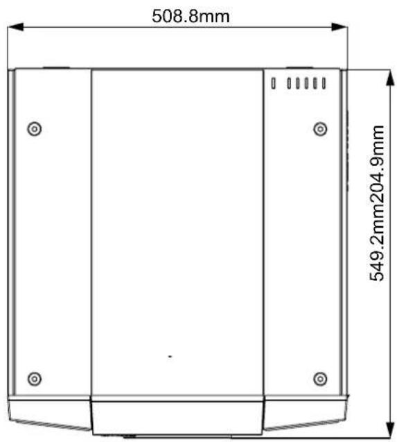
text_image
508.8mm 549.2mm204.9mm
text_image
508.8mm549.2mm
text_image
230.3mm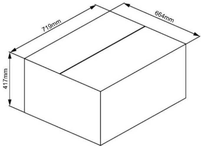
text_image
719mm 664mm 417mm
text_image
508.8 254.9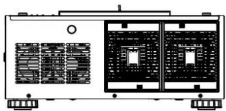
natural_image
Technical line drawing of a dual-chamber industrial machine with heat sinks and control panel (no text or symbols)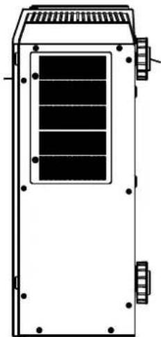
natural_image
Technical line drawing of a rectangular industrial or electrical enclosure with internal compartments and mounting feet (no text or symbols)
text_image
Use 6pcs M4 screws. Lenth max=15mm to fix this machine on the ceiling mount. 150 1.50 1.50 108.8 104.4 300 549.8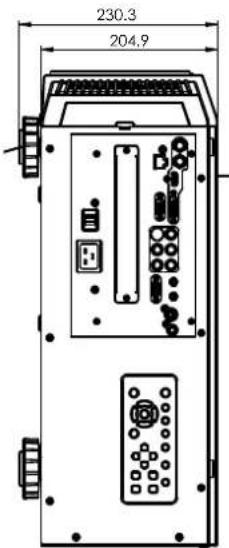
text_image
230.3 204.9
natural_image
Simple line drawing of a rectangular enclosure or cabinet with mounting holes and vertical supports (no text or symbols)SUPPORTED TIMINGS
| Signal Type | Resolution | Frame rate | DVI Video SCART S- | Video Y-Pb-Pr HD15-YUV | HD15-RGB | |||
| PC | 640x480 59 | 94 X X | ||||||
| 640x480 74 | 99 X X | |||||||
| 640x480 85 | X X | |||||||
| 800x600 60 | .32 X X | |||||||
| 800x600 75 | X X | |||||||
| 800x600 85 | 06 X X | |||||||
| 848x480 | 47.95 | X X | ||||||
| 848x480 | 59.94 X X | |||||||
| 1024x768 60 | X X | |||||||
| 1280x1024 | 60.02 | X X | ||||||
| 1280x1024 | 75.02 | X X | ||||||
| 1280x1024 | 85.02 X X | |||||||
| 1600x1200 | 60 | X X | ||||||
| 1680x1050 | 59.954 | X X | ||||||
| 1920x1080 | 47.95 | X X | ||||||
| Apple Mac | 640x480 66 | 59 X X | ||||||
| SDTV | RGBs | 50 | X | |||||
| 1440x480i | 60 | X | ||||||
| 1440x576i | 50 | X | ||||||
| 480i | 59.94 | X | ||||||
| 576i | 50 | X | ||||||
| EDTV | 480p | 59.94 | X | X | X | X | ||
| 576p | 50 | X | X | X | X | |||
| HDTV | 1035i | 60 | X | X | X | X | ||
| 1080i | 50 | X | X | X | X | |||
| 1080i (Aus) | 50 | X | X | X | X | |||
| 1080i | 59.94 | X | X | X | X | |||
| 1080i | 60 | X | X | X | X | |||
| 720p | 50 | X | X | X | X | |||
| 720p | 59.94 | X | X | X | X | |||
| 720p | 60 | X | X | X | X | |||
| 1080p | 23.98 | X | X | X | X | |||
| 1080p | 24 | X | X | X | X | |||
| 1080p | 25 | X | X | X | X | |||
| 1080p | 29.97 | X | X | X | X | |||
| 1080p | 30 | X | X | X | X | |||
| 1080p | 50 | X | X | X | X | |||
| 1080p | 59.94 | X | X | X | X | |||
| 1080p | 60 | X | X | X | X | |||
| NTSC | NTSC(M 4.43) | 59.94 | X | X | ||||
| PAL | PAL(B,G,H,I) | 50 | X | X | ||||
| PAL (N) | 50 | X | X | |||||
| PAL (M) 59.94 | X | X | ||||||
| SECAM | SECAM (M) | 50 | X | X | ||||
PROJECTION DISTANCE AND SCREEN SIZE
Optional Lenses (D88-LOZ101)
Long Zoom 1 Lens Features and Specifications
•Motorized Zoom and Focus
• Lens Shift Position: 0-50% Vertical; +/-10% Horizontal
• Focus adjustable Range: 40" - 500"
•Optical Performance Range: 50" - 300"
•F-Number: 1.85 - 2.41
•Focal Length: 52.8-79.1mm
•Screen Size: 50"-300"
•Zoom Ratio: 1.5:1
- Throw Distance Ratio: 3.71-5.57:1 (XGA); 3.76-5.64:1 (WXGA); 3.58-5.38:1 (WUXGA)
Projection Distance V.S. Projection Size
| D88-LOZ101Long Zoom 1 Lens | XG | WXG | WUXGA | |||
| Projection Distance (m) +/-10% | Projection Distance (m) +/-10% | Projection Distance (m) +/-10% | ||||
| Screen Size (inch) | Minimum | Maximum | Minimum | Maximum | Minimum | Maximum |
| Wide | Tele | Wide | Tele | Wide | Tele | |
| 40 | 2.94 | 4.49 | 3.17 | 4.83 | 3.01 | 4.6 |
| 50 | 3.71 | 5.65 | 4.00 | 6.08 | 3.8 | 5.78 |
| 60 | 4.48 | 6.80 | 4.83 | 7.32 | 4.59 | 6.96 |
| 80 | 6.02 | 9.12 | 6.48 | 9.80 | 6.16 | 9.33 |
| 100 | 7.56 | 11.43 | 8.14 | 12.29 | 7.73 | 11.7 |
| 120 | 9.10 | 13.74 | 9.79 | 14.77 | 9.31 | 14.06 |
| 150 | 11.41 | 17.21 | 12.27 | 18.50 | 11.67 | 17.61 |
| 180 | 13.72 | 20.68 | 14.75 | 22.22 | 14.03 | 21.16 |
| 200 | 15.26 | 22.99 | 16.41 | 24.71 | 15.6 | 23.53 |
| 300 | 22.95 | 34.56 | 24.68 | 37.13 | 23.47 | 35.36 |
| 400 | 30.65 | 46.12 | 32.95 | 49.55 | 31.34 | 47.19 |
| 500 | 38.34 | 57.69 | 41.22 | 61.97 | 39.21 | 59.02 |
Optional Lenses (D88-LOZ201)
Long zoom 2 Lens Features and Specifications
•Motorized Zoom and Focus
• Lens Shift Position: 0-50% Vertical; +/-10% Horizontal
• Focus adjustable Range: 40" - 500"
•Optical Performance Range: 50" - 300"
•F-Number: 1.85 - 2.48
•Focal Length: 78.5-121.9mm
•Screen Size: 50"-300"
•Zoom Ratio: 1.55:1
- Throw Distance Ratio: 5.5-8.56:1(XGA); 5.56-8.67:1(WXGA); 5.31-8.26:1(WUXGA)
Projection Distance V.S. Projection Size
| D88-LOZ201Long Zoom 2 Lens | XG | WXG | WUXGA | |||
| Projection Distance (m) +/-10% | Projection Distance (m) +/-10% | Projection Distance (m) +/-10% | ||||
| Screen Size (inch) | Minimum | Maximum | Minimum | Maximum | Minimum | Maximum |
| Wide | Tele | Wide | Tele | Wide | Tele | |
| 40 | 4.31 | 6.89 | 4.65 | 7.42 | 4.42 | 7.05 |
| 50 | 5.46 | 8.68 | 5.89 | 9.35 | 5.59 | 8.89 |
| 60 | 6.61 | 10.48 | 7.13 | 11.28 | 6.77 | 10.73 |
| 80 | 8.91 | 14.07 | 9.60 | 15.13 | 9.13 | 14.4 |
| 100 | 11.22 | 17.66 | 12.08 | 18.99 | 11.48 | 18.07 |
| 120 | 13.52 | 21.25 | 14.55 | 22.85 | 13.84 | 21.75 |
| 150 | 16.97 | 26.64 | 18.27 | 28.63 | 17.37 | 27.26 |
| 180 | 20.42 | 32.03 | 21.98 | 34.42 | 20.91 | 32.77 |
| 200 | 22.73 | 35.62 | 24.45 | 38.28 | 23.26 | 36.44 |
| 300 | 34.24 | 53.57 | 36.83 | 57.56 | 35.04 | 54.81 |
| 400 | 45.75 | 71.53 | 49.20 | 76.85 | 46.82 | 73.18 |
| 500 | 57.26 | 89.48 | 61.58 | 96.13 | 58.6 | 91.54 |
Optional Lenses (D88-SMLZ01)
Semi Long Zoom Lens Features and Specifications
•Motorized Zoom and Focus
• Lens Shift Position: 0-50% Vertical; +/-10% Horizontal
• Focus adjustable Range: 40" - 500"
•Optical Performance Range: 50" - 300"
•F-Number: 1.86 - 2.48
Projection Distance V.S. Projection Size
•Focal Length: 32.9-54.2mm
•Screen Size: 50"-300"
•Zoom Ratio: 1.65:1
- Throw Distance Ratio: 2.3-3.81(XGA); 2.33-3.86:1(WXGA); 2.22-3.67: 1(WUXGA)
| D88-SMLZ01 Semi Long Zoom Lens | AGX | AGX | WUXGA | |||
| Projection Distance (m) +/-10% | Projection Distance (m) +/-10% | Projection Distance (m) +/-10% | ||||
| Screen Size (inch) | Minimum | Maximum | Minimum | Maximum | Minimum | Maximum |
| Wide | Tele | Wide | Tele | Wide | Tele | |
| 40 | 1.83 | 3.08 | 1.97 | 3.31 | 1.87 | 3.15 |
| 50 | 2.30 | 3.87 | 2.48 | 4.16 | 2.36 | 3.96 |
| 60 | 2.78 | 4.66 | 3.00 | 5.01 | 2.85 | 4.77 |
| 80 | 3.73 | 6.24 | 4.02 | 6.71 | 3.82 | 6.39 |
| 100 | 4.69 | 7.82 | 5.05 | 8.41 | 4.80 | 8.00 |
| 120 | 5.64 | 9.40 | 6.07 | 10.10 | 5.78 | 9.62 |
| 150 | 7.07 | 11.77 | 7.61 | 12.65 | 7.24 | 12.04 |
| 180 | 8.50 | 14.14 | 9.15 | 15.19 | 8.70 | 14.47 |
| 200 | 9.46 | 15.72 | 10.17 | 16.89 | 9.68 | 16.08 |
| 300 | 14.23 | 23.62 | 15.30 | 25.38 | 14.56 | 24.16 |
| 400 | 18.99 | 31.52 | 20.42 | 33.86 | 19.44 | 32.25 |
| 500 | 23.76 | 39.42 | 25.55 | 42.35 | 24.32 | 40.33 |
Optional Lenses (D88-ST001)
STD Lens Features and Specifications
•Motorized Zoom and Focus
• Lens Shift Position: 0-50% Vertical; +/-10% Horizontal
• Focus adjustable Range: 40" - 500"
•Optical Performance Range: 50" - 300"
•F-Number: 1.7 - 1.9
•Focal Length: 26 - 34mm
•Screen Size: 50"-300'
•Zoom Ratio: 1.3:1
- Throw Distance Ratio: 1.79-2.35:1(XGA); 1.81-2.38:1(WXGA); 1.73-2.27:1 (WUXGA)
Projection Distance V.S. Projection Size
| D88-ST001 STD Lens | AGX | AWGX | WUXGA | |||
| Projection Distance (m) +/-10% | Projection Distance (m) +/-10% | Projection Distance (m) +/-10% | ||||
| Screen Size (inch) | Minimum | Maximum | Minimum | Maximum | Minimum | Maximum |
| Wide | Tele | Wide | Tele | Wide | Tele | |
| 40 | 1.42 | 1.88 | 1.53 | 2.03 | 1.45 | 1.93 |
| 50 | 1.79 | 2.37 | 1.93 | 2.55 | 1.83 | 2.42 |
| 60 | 2.16 | 2.86 | 2.33 | 3.07 | 2.21 | 2.92 |
| 80 | 2.90 | 3.83 | 3.13 | 4.12 | 2.97 | 3.92 |
| 100 | 3.65 | 4.80 | 3.93 | 5.17 | 3.73 | 4.92 |
| 120 | 4.39 | 5.78 | 4.72 | 6.22 | 4.49 | 5.91 |
| 150 | 5.50 | 7.24 | 5.92 | 7.79 | 5.63 | 7.41 |
| 180 | 6.62 | 8.70 | 7.12 | 9.36 | 6.77 | 8.9 |
| 200 | 7.36 | 9.67 | 7.92 | 10.40 | 7.53 | 9.9 |
| 300 | 11.07 | 14.54 | 11.91 | 15.64 | 11.33 | 14.88 |
| 400 | 14.79 | 19.41 | 15.90 | 20.88 | 15.13 | 19.87 |
| 500 | 18.50 | 24.28 | 19.90 | 26.11 | 18.93 | 24.85 |
Optional Lenses (D88-WF18501)
Wide Fix Lens Features and Specifications
nethatol6sucof dezirotoM•
•Lens Shift Position: 0%
•Screen Size: 50"-300"
• Focus adjustable Range: 40" - 500"
- Zoom Ratio: N/A
•Optical Performance Range: 50" - 300"
- Throw Distance Ratio: 0.79:1(XGA); 0.8:1(WXGA); 0.76:1(WUXGA)
•F-Number: 1.85
Projection Distance V.S. Projection Size
| D88-WF18501Wide Fix Lens | XGA | WXGA | WUXGA |
| Projection Distance (m) +/-10% | Projection Distance (m) +/-10% | Projection Distance (m) +/-10% | |
| Screen Size (inch ) | Wide | ediW | ediW |
| 40 | 0.62 | 0.67 | 0.64 |
| 50 | 0.79 | 0.85 | 0.81 |
| 60 | 0.96 | 1.03 | 0.98 |
| 80 | 1.29 | 1.39 | 1.32 |
| 100 | 1.62 | 1.75 | 1.66 |
| 120 | 1.96 | 2.11 | 2.01 |
| 150 | 2.46 | 2.64 | 2.52 |
| 180 | 2.96 | 3.18 | 3.03 |
| 200 | 3.3 | 3.54 | 3.37 |
| 300 | 4.97 | 5.33 | 5.08 |
| 400 | 6.64 | 7.13 | 6.79 |
| 500 | 8.31 | 8.92 | 8.5 |
Optional Lenses (D88-WZ01)
Wide Zoom Lens Features and Specifications
•Motorized Zoom and Focus
•Focal Length: 18.7-26.5mm
•Lens Shift Position: 0-50% Vertical; +/-10% Horizontal
•Screen Size: 50"-300"
• Focus adjustable Range: 40" - 500"
•Zoom Ratio: 1.41:1
•Optical Performance Range: 50" - 300"
- Throw Distance Ratio: 1.3-1.85:1(XGA); 1.31-1.87:1(WXGA); 1.25-1.79:1(WUXGA)
•F-Number: 1.85 - 2.5
Projection Distance V.S. Projection Size
| D88-WZ01Wide Zoom Lens | X GA | WX | WUXGA | |||
| Projection Distance (m) +/-10% | Projection Distance (m) +/-10% | Projection Distance (m) +/-10% | ||||
| Screen Size (inch) | Minimum | Maximum | Minimum | Maximum | Minimum | Maximum |
| Wide | Tele | Wide | Tele | Wide | Tele | |
| 40 | 1.03 | 1.49 | 1.11 | 1.60 | 1.02 | 1.51 |
| 50 | 1.30 | 1.87 | 1.40 | 2.01 | 1.29 | 1.9 |
| 60 | 1.57 | 2.25 | 1.69 | 2.43 | 1.56 | 2.29 |
| 80 | 2.11 | 3.02 | 2.27 | 3.25 | 2.1 | 3.07 |
| 100 | 2.65 | 3.79 | 2.85 | 4.08 | 2.64 | 3.85 |
| 120 | 3.18 | 4.56 | 3.43 | 4.90 | 3.18 | 4.63 |
| 150 | 3.99 | 5.71 | 4.30 | 6.14 | 3.99 | 5.8 |
| 180 | 4.80 | 6.86 | 5.17 | 7.38 | 4.8 | 6.97 |
| 200 | 5.34 | 7.63 | 5.75 | 8.20 | 5.33 | 7.75 |
| 300 | 8.04 | 11.47 | 8.65 | 12.33 | 8.03 | 11.65 |
| 400 | 10.74 | 15.31 | 11.55 | 16.45 | 10.72 | 15.56 |
| 500 | 13.44 | 19.14 | 14.45 | 20.58 | 13.42 | 19.46 |