Auscul - Headphones Blood Cells Audio - Free user manual and instructions
Find the device manual for free Auscul Blood Cells Audio in PDF.

User questions about Auscul Blood Cells Audio
0 question about this device. Answer the ones you know or ask your own.
Ask a new question about this device
Download the instructions for your Headphones in PDF format for free! Find your manual Auscul - Blood Cells Audio and take your electronic device back in hand. On this page are published all the documents necessary for the use of your device. Auscul by Blood Cells Audio.
USER MANUAL Auscul Blood Cells Audio
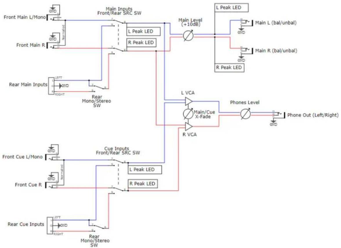
Output Module with Flexible I/O, Balanced Outputs, and VCA Headphone Cue Monitoring
text_image
AUSCULT MAIN OUTPUTS BRL/UNBL L R REAR SRC PK MAIN INPUTS L/Mono R REAR SRC CUE INPUTS L/Mono R PK SRC MAIN CUE (TRS ONLY) LEVEL +4 -10 MAIN OUT M 0 10 ∞ +10dB BCACompliance

This product is in conformity with the following standards:
EN 55032:2012/AC:2013, EN 55035:2017, EN 61000-3-2:2014, EN 61000-3-3:2013
RoHS2: 2011/65/EU
WEEE: 2012/19/EU
Overview
Auscultation is the act of listening to the internal sounds of the body during a medical examination, typically with a stethoscope. While you can't listen to your internal organs with this module, you can easily tap into the sounds of your modular in some useful ways.
Auscult is a main output and monitoring module for eurorack, with some extra-unique features. All inputs are either mono or stereo, and the impedance-balanced outputs provide up to +10dB of gain. There is a headphone cue monitoring system that uses a VCA crossfader to help you audition fresh sounds against your existing main mix, at whatever level you set with the headphone source knob. In addition, there is a quality headphone amplifier with two switchable output levels, making it capable of driving even very high-impedance headphones.
Finally, additional mono/stereo Main and Cue Input connections on the rear of the module allow for connecting to another module's expansion connectors (also ripe for DIY'ers). This leaves the front panel inputs open for use with other modules and on-the-fly connections. Easily flip between the front and rear connections using switches on the front panel.
Features:
• Balanced outputs with gain up to +10 dB.
- VCA crossfade monitoring system for auditioning Cue input against the Main Mix in headphones.
- Switchable Headphone output levels for driving even super high-impedance headphones.
- Mono/stereo Cue and Main Inputs are switchable between the front and rear connections.
- Peak LEDs for all inputs and main outs.
WHAT'S IN THE BOX!?
- Auscult module
- 4 screws for mounting in your eurorack
- Ribbon cable for power
- 3-pin cable for expansion (x2)
Anatomy (Front Panel)
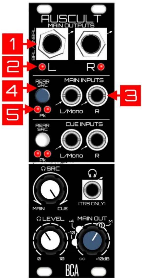
- Main Outputs: Balanced outputs - Plug in a 14 " (6.35mm) TRS or TS (unbalanced is also fine). Route to recording interface or to house system, etc. Output level is determined by the Main Out knob (see #12 below). Avoid accidentally having phantom power from your recording interface/mixer on. There is built in protection for overvoltage, but best practice is to...not.
- Main Output Peak LEDs: Peak-detection at about 10 Volts. This leaves a bit of headroom before things truly begin to distort the outputs of Auscult (note, these peak when you've exceeded your headroom at modular voltage level).
- Main Inputs Section: Typically if you have some sort of mixer upstream from Auscult, you'd plug the main outs of that into these Main Inputs. If the source is mono, plug it into the L/Mono jack and it will automatically be normalled into the right channel. This audio routes to both the Main Outputs of Auscult, as well as to the headphones (assuming the headphone SRC knob is set to monitor the Main Input. See #9 below).
- Main Inputs Rear SRC Switch: This switch is the source selector for which of the Main Inputs (front or rear) get routed to the Main Outputs/headphones. When the switch is off, the inputs on the front panel are selected. When the switch is on (pushed in), the inputs on the rear are selected. Note it is not possible to mix both front and rear sources together.
- Main Input Peak LEDs: These are post SRC Switch.
text_image
AUSCULT MAIN OUTPUTS BELL/NBRAL L R 1 2 4 5 REAR SRC MAIN INPUTS L/Mono R 3 PK REAR SRC CUE INPUTS L/Mono R PK BCA Ω SRC MAIN CUE (TRS ONLY) LEVEL +4 MAIN OUT M 0 10 ∞ +10dB- Cue Inputs Section: This is where you plug in the source you want to privately audition against your main input. If the source is mono, plug it into the L/Mono jack and it will automatically normal into the right channel. Whatever source is plugged into Cue only routes to the headphone output (assuming the headphone SRC knob is set to allow Cue signal to pass. See #9 below).
- Cue Inputs Rear SRC Switch: See #4 above. Same idea.
- Cue Input Peak LEDs: See #5 above.
- Headphone SRC: This is the VCA crossfader that determines the mix ratio between the Main Inputs and the Cue Inputs in your headphones. At 12 o'clock, the mix between them is equal. At the extremes, it's 100% one or the other. It's useful to have a way to quickly (and musically) mix between Main or Cue, considering the varying levels of sources you might plug into the Cue Input. It's not always going to be 12 o'clock.
- Headphone Level: This is of course the volume control for your headphones. Auscult ships in "normal" mode as far as Max Levels go, which is best for typical headphone impedances. (see #3 in Rear Panel Anatomy for Max Levels). Use common sense as even in Normal mode, it can get very loud. Oh, it's time for my PSA:
Public Service Announcement - Before changing to a different pair of headphones (or changing headphone settings on the back of the module), always first turn down the headphone level! As an example, changing from high-impedance headphones to low-impedance

text_image
AUSCULT MAIN OUTPUTS BRAL / UNBRL L R REAR SRC MAIN INPUTS L/Mono R Pk REAR SRC CUE INPUTS L/Mono R Pk 6 7 8 9 10 SRC MAIN CUE (TRS ONLY) LEVEL MAIN OUT 0 10 ∞ +10dB BCAheadphones without first turning the gain down could very well be damaging to your ears (due to higher power being dumped into your lower-impedance headphones). Blood Cells Audio will not be responsible for ruined ears, headphones, nor pants.
- Headphone Output: 18 " (3.5mm) TRS jack for your phones. It's best to only plug TRS into this jack - being modular, it's possible to plug in a TS jack here. Not recommended, as the right channel of the chip inside will then be shorted to ground through the sleeve of your TS cable. There is protection to keep the chip from dying, even with your headphones levels utterly cranked to the max, but again it's just best practice.
- Main Out Knob: This knob controls the level leaving the Main Outputs, from off up to a max of +10dB. The Unity mark (2 circles) represents unity gain, meaning the level leaving Auscult will match the levels coming into the Main Inputs. The other level markings for +4 (dBu) and -10 (dBV) are for getting you in the proper ballpark when connecting to other devices such as recording interfaces, assuming the Input source is nominal modular level (see FAQ for more info).
text_image
AUSCULT MAIN OUTPUTS BR/L/UNBRL L R REAR SRC PK MAIN INPUTS L/Mono R REAR SRC PK CUE INPUTS L/Mono R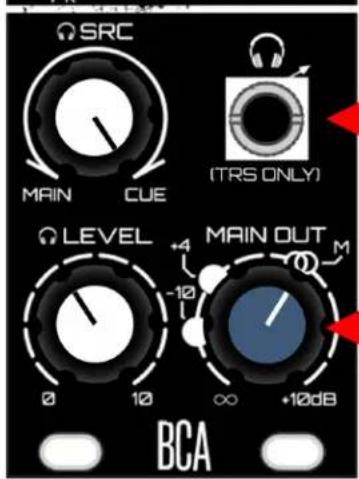
text_image
SRC MAIN CUE (TRS ONLY) LEVEL MAIN OUT -10 0 10 ∞ +10dB BCA
Anatomy (Rear Panel)
1. Rear Main Connector / Rear Main Input
Mode: Use the 3-pin connector to hook in other modules behind-the-scenes. Could be used for a future BCA module, somebody else's modules, or your own DIY! The pinout is marked - as long as you match the signals to the other module, you'll be cool. It's easy to modify the 3-pin cables that come with Auscult. If the source is mono, Just use the Left/Mono and GND connections, leaving Right unconnected. Then be sure to flip the Input Mode switch to Mono - this will route the Left/Mono channel into the Right channel.
Be sure to keep the 3-pin jumper that is on there, and reinstall it if not wired up. Unterminated connections aren't ideal. It won't hurt anything to leave it off, but if you flip the SRC switch to the rear without the jumper, you may hear a bit of the front connection bleeding in if the rear is unterminated. This jumper prevents that.
These inputs are expecting modular levels, are AC-coupled, and are also protected from overvoltages (for you DIY'ers).
2. Rear Cue Connector / Rear Cue Input
Mode: See #1 above, all the same applies.

text_image
1 2 REAR MAIN MAIN INPUT MODE REAR CUE INPUT MODE REAR CUE INPUT MODE R GND LM ST. M R GND LM BLOOD CELLS AUDIO WWW.BLOODCELLSAUDIO.COM MAX LEVELS (CAUTION) NORMAL LOUD AF! +12V GND O -12V O- Headphone Max Levels: When changing modes, always turn down the headphone gain first! Please don't hurt yourself.
Normal Setting: This is the default and is used for typical low-impedance headphones. Start with this setting...it still gets plenty loud!
Loud AF setting: Loud AF = Loud As Fxck. So take extreme caution when changing to this setting, as you could damage your hearing or perhaps your headphones. Always start with the headphone gain down, then switch it. Bring it up easy! Use LAF only for high-impedance headphones, for instance the Beyerdynamic DT-990 (600 ohms).
One last Public Service Announcement (again I'm so sorry) - Before changing to a different pair of headphones, or changing headphone settings on the back of the module, always first turn down the headphone gain! As an example, changing from high impedance headphones to low impedance headphones without first turning the gain down could very well be damaging to your ears (due to higher power being dumped into your lower impedance headphones). Blood Cells Audio will not be responsible for ruined pants and/or ears.
- Power: Yes.

text_image
CE Lead-fire/ Pb REAR MAIN MAIN INPUT MODE REAR CUE INPUT MODE R M GND LM ST M R GND LM BLOOD CLEVEL AUDIO WWW.BLOOD CLEVELAUDIO.COM MAX LEVELS (CAUTION) NORMAL LOUD AF 12V 4 GNDO -12V OAdditional Notes / FAQ:
Main Output Gain:
Some might wonder why we would bother with an additional +10dB of gain on the Main Output, considering Auscult already puts out modular levels, and it's likely wired into something that is line level anyway. The reasoning is simple - I think it's more flexible that way! Perhaps you have a mixer upstream from Auscult, and on the fly you've dialed in a mix you dig...but dammit Jim, you spaced out on your settings, and the overall mix level is somewhat low. What can you do?
Well, you can do one of two things:
-
The proper thing, if you have the time/inclination, would be to adjust your mix's gain structure properly for optimal signal-to-noise ratio.
-
Or in the heat of the moment, you can use Auscult's main output knob to give up to +10dB of make up gain and move on with creativity. Yes, of course you'll also be boosting the noise floor as you do this, which can be risky - but if the result sounds good, it's good as they say. Know that BCA modules use nice opamps and are designed to be quiet. You'll likely get away with "cheating", especially if the mixer upstream happens to be an also quiet D.O.MIXX.
Main Output Gain Markings and "Proper Levels":
It was considered to add a +4 dBu/-10 dBV switch, or even just hard set the output to a certain level. But let's face it - with the magical non-standard chaos of eurorack, as far as I'm concerned you'll be putting an unknown voltage source into this module. Also who knows what everybody will plug this into. A knob that gives you all the options from completely all the way off, up to "modular +10dB" is more flexible to me. I can look at a recording interface's input meters, adjust the main outs of Auscult to get a good signal-to-noise ratio, and feel solid that I have a good and full output range to work with.
That said, the +4 and -10 markings can be useful, just know that their placement around the knob is based on the source being at a nominal modular level of 10 Volts peak-to-peak (Vpp). If that's the case, the +4/-10 markings are spot on. If the source isn't a perfect 10 Vpp, the markings may still give you a ballpark idea of where +4/-10 is in relation to modular unity gain. Or just ignore them completely and adjust while checking the input meters on the receiving device to dial it in (or listen to the sound person shouting out "Give me more! Wait, a little less! OK right there! No, sorry a little more! OK cool!!").
Signal Flow (Simplified)
flowchart
graph TD
    A["Front Main L/Mono"] --> B["Main Inputs Front/Rear SRC SW"]
    C["Front Main R"] --> D["L Peak LED"]
    E["Rear Main Inputs"] --> F["LEFT Mono/Stereo SW"]
    G["Front Cue L/Mono"] --> H["Cue Inputs Front/Rear SRC SW"]
    I["Front Cue R"] --> J["L Peak LED"]
    K["Rear Cue Inputs"] --> L["LEFT Mono/Stereo SW"]
    B --> M["Main Level (+10dB)"]
    D --> M
    F --> N["L VCA"]
    H --> O["Main/Cue X-Fade"]
    J --> P["R VCA"]
    M --> Q["L Peak LED"]
    N --> R["Phone Out (Left/Right)"]
    O --> S["Main L (bal/unbal)"]
    P --> T["Main R (bal/unbal)"]
    Q --> U["L Peak LED"]
    R --> V["Main L (bal/unbal)"]
    S --> W["L Peak LED"]
    T --> X["Main L (bal/unbal)"]
    U --> Y["R Peak LED"]
    V --> Z["R Peak LED"]
Installation
This module takes up 8HP of space.
Dealing with Power: First calculate how much total current your eurorack setup is consuming from the supply's +12V rail, as well as the -12V rail (Modular Grid is a great resource for this). Add the current consumption of this module's +/- 12V rails (find this in specs below) to those numbers...as long as you're below the current capacity of each of the supply rails, you're golden. If not - don't plug this in yet, as either a beefier supply is needed, or some modules will need to be unplugged to accommodate.
Plugging it in: Turn off your power supply, then plug the 16-pin side of the included ribbon cable into an available power header. The red stripe must be on the -12V side of the supply's header. When in doubt, check the documentation of your supply. Connect the ribbon cable to the BCA module's power header on the rear. The position of the -12V red stripe is clearly labeled - in fact there's no way to get that backwards since the header is keyed (unless you defeat it by clipping something off, in which case the built-in reverse voltage protection should save you - but still please don't do that).
Technical Specs
| Width | 8HP |
| Depth | 3.3 cm |
| Power | 85 mA @ 12V85 mA @ -12V |
| Output Gain | ∞ to +10 dB (modular level) |
| Inputs/Outputs | Unbalanced modular inputs.Impedance-Balanced Outputs (Unbalanced is fine too) |
| Input Impedance | 100K ohms |
| Output Impedance | 330 ohms |