221.x2 - Audio Blood Cells Audio - Free user manual and instructions
Find the device manual for free 221.x2 Blood Cells Audio in PDF.

User questions about 221.x2 Blood Cells Audio
0 question about this device. Answer the ones you know or ask your own.
Ask a new question about this device
Download the instructions for your Audio in PDF format for free! Find your manual 221.x2 - Blood Cells Audio and take your electronic device back in hand. On this page are published all the documents necessary for the use of your device. 221.x2 by Blood Cells Audio.
USER MANUAL 221.x2 Blood Cells Audio
Expandable 4-Channel Audio and CV Utility Mix, Attenuate, Invert
text_image
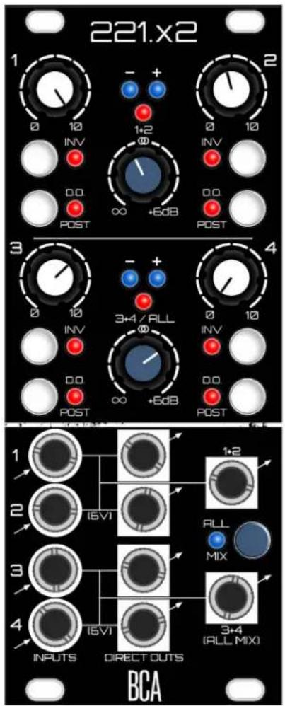
221.x2 1 - + - 0 10 INV 1+2 φ 0 10 0.0 POST ∞ +6dB 0.0 POST 3 - + - 0 10 INV 3+4 / RLL φ 0 10 0.0 POST ∞ +6dB 0.0 POST 4 1 - + - 2 (I-VI) 1+2 ALL MIX 3 - 4 (I-VI) 3+4 (ALL MIX) INPUTS DIRECT OUTS BCACompliance

This product is in conformity with the following standards:
EN 55032:2012/AC:2013, EN 55035:2017, EN 61000-3-2:2014, EN 61000-3-3:2013
RoHS2: 2011/65/EU
WEEE: 2012/19/EU
Overview
221.x2 is a clean and precise utility module that is as equally at home manipulating Control Voltage as it is audio. At its simplest, it is two independent 2-to-1 mixers that offer per-channel attenuation and inversion, as well as +6dB of gain available at the summed outputs. With a tap of the "All Mix" button, these separate mixes can be combined into a 4-to-1 mix at the "All Mix" output - meanwhile, the first 1+2 mix is still available at its respective summed output. A rear expansion input and output allows for combining multiple modules into larger systems.
However the 221 is not just a mixer, as each channel also offers a Direct Output that can be taken pre or post attenuation/inversion for per-channel manipulation. The Direct Outputs are precise to an average of .8mV of error (if not better) under a typical 100K eurorack load, which equates to less than 1 cent of error when working with pitch CV.
A 6-volt offset is normalled into the input jacks of channels 2 and 4. This voltage is available at the channel's Direct Output, as well as added to the mixed outputs. Useful as an offset for mixing with another CV signal, or simply as a voltage source.
Each summed output group has two blue LEDs for displaying the shape of the summed CV, and can also serve as signal present indicators for audio. Peak LEDs trigger at \~9.6V, allowing for a bit of headroom before things get out of hand.
Features:
- Clean and precise manipulation, routing and mixing of CV and Audio signals.
- Switchable mixer configurations: two 2-to-1 mixes, or one 2-to-1 plus a 4-to-1.
- Expandable with other 221.x2 modules.
- Direct Outs are switchable between Pre and Post attenuation/inversion.
- Channels 2 and 4 are normalled with a 6V offset.
- to +6 dB of gain on Summing knobs.
- LEDs for bipolar peak detection, and display of CV shape.
WHAT'S IN THE BOX?
- 221.x2 module
- 4 screws for mounting in your eurorack
- Ribbon cable for power
- 2-pin cable for expansion
Anatomy (Front Panel)
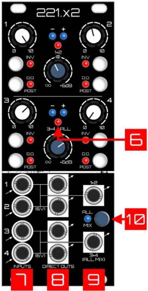
- Channel Attenuators: These potentiometers have linear action. Note, in DO PRE Mode, these attenuators will only affect the level sent to the Mix Outputs (see #3 below)..
- Invert Button: When on, inverts the audio or CV. Note that in DO PRE Mode, the invert button will only affect the Mix Outputs (see #3 below).
- DO POST Button: Flips between two modes that determine which signals get routed to the Direct Outputs.
a. DO POST Mode (button on): Signals sent to the channel's Direct Output are post attenuation/inversion.
b. DO PRE Mode (button off): Signals are routed through a single precision opamp straight to the Direct Outputs.
Attenuation/Inversion are bypassed. This allows an untouched “copy” of the input to leave via the DO’s, while allowing the signal to be manipulated separately to the mix outputs.
- Summed Output Gain (1+2 and 3+4 / ALL): The level controls for the 2 summed outputs, from off to +6dB. These are linear potentiometers with unity up the middle.
- -/+ CV LEDs: Useful when working with CV. These will give you a visual of whatever weird waveforms you've summed together. Note, these LEDs will also light up with audio, and will flicker more obviously as the frequency of audio is drastically reduced to something the eye can actually see. When working with audio, think of them as simple "audio present" indicators.

- Peak LEDs: Bipolar peak-detection at about +/- 10 Volts. This leaves a bit of headroom before things truly begin to distort.
- Signal Inputs: Plug in Audio or CV signals. Unbalanced. Inputs 2 and 4 have 6V normalled into their jacks - so when un-patched, they can be used as a voltage offset when summed with the other channel in their group, or as a simple voltage source out the Direct Output. This offset can be manipulated with the channel controls. Inputs 1 and 3 short to ground when unplugged. Inputs 2 and 4 do not short to ground due to the built-in offset, thus if they are un-patched, it's best to turn them down to avoid any accidental DC offset in your mix.
- Direct Outputs: Unbalanced. Audio or CV taken Pre-mix (as you can see from the lines on front panel). These are switchable between Pre or Post attenuation/inversion (see item #3 above).
- Summed Outputs: Unbalanced. The summed outputs for each pair of channels (1+2 and 3+4).
- All Mix Button: Combines the 1+2 Mix with the 3+4 mix thus creating a 4-to-1 mix. This full mix will appear at the 3+4 (ALL MIX) output, as well as the Expansion Output on the rear. In this mode, the 1+2 mix is still available independently at its output.
text_image
221.x2 1 - + - 0 10 INV 1+2 ∞ 0 10 INV 0.0 POST ∞ +5dB 0.0 POST 3 - + - 0 10 3+4 ALL 0 10 INV 0.0 POST ∞ +5dB 0.0 POST 6 OUTPUTS DIRECT OUTS 7 8 9 1+2 10 ALL MIXAnatomy (Rear Panel)
-
Expansion Output: Connect this output to another 221.x2's Expansion Input. This output is a pre-gaincopy of the "3+4 / ALL MIX" bus. The 2nd receiving 221.x2 will now have up to an 8-to-1 mix at its All Mix output. DC-Coupled.
-
Expansion Input: Connect the Expansion Output of another 221.x2 into this input with the included 2-pin cable. Whatever comes into this input will be added into the main "ALL MIX" bus. DC-Coupled.

text_image
CE TP 1+2 Bus RED I-12VI Pb Lead-free EXP OUT 1 G TP PreMix3 TP PreMix4 TopSum3+4 Sum3+4 Out TopSum1+2 Sum1+2 Out TP PreMix2 TP PreMix1 TP PreMix0 TP PreMix1 TP PreMix0 TP PreMix1 TP PreMix0 TP PreMix1 TP PreMix0 TP PreMix1 TP PreMix0 TP PreMix1 TP PreMix0 TP PreMix1 TP PreMix0 TP PreMix1 TP PreMix0 TP PreMix1 TP PreMix0 TP PreMix1 TP PreMix0 TP PreMix1 TP PreMix1 TP PreMix0 TP PreMix1 TP PreMix0 TP PreMix1 TP PreMix0 TP PreMix1 TP PreMix0 TP PreMix1 TP PreMix0 TP PreMix1 TP PreMix0 TP PreMix1 TP PreMix0 TP PreMix1 TP PreMix0 TP PreMix1 TP PreMix0 TP PreMix1 TP PreMixO TP PreMix1 TP PreMix0 TP PreMix1 TP PreMix0 TP PreMix1 TP PreMix0 TP PreMix1 TP PreMix0 TP PreMix1 TP PreMix0 TP PreMix1 TP PreMix0 TP PreMix1 TP PreMix0 TP PreMix1 TP PreMix0 TP PreMix1 TP PreMix0 TP PreMix1 TP PreMixo TP PreMix1 TP PreMix0 TP PreMix1 TP PreMix0 TP PreMix1 TP PreMix0 TP PreMix1 TP PreMix0 TP PreMix1 TP PreMix0 TP PreMix1 TP PreMix0 TP PreMix1 TP PreMix0 TP PreMix1 TP PreMix0 TP PreMix1 TP PreMix0 TP PreMix1 TP PreMixa TP PreMix1 TP PreMix0 TP PreMix1 TP PreMix0 TP PreMix1 TP PreMix0 TP PreMix1 TP PreMix0 TP PreMix1 TP PreMix0 TP PreMix1 TP PreMix0 TP PreMix1 TP PreMix0 TP PreMix1 TP PreMix0Helpful Tips/Reminders:
- Pay attention to the 6V of DC Offset on channels 2 and 4. As briefly mentioned above, if either of these channels is unpatched, it's possible to accidentally add some epic DC offset into the mix outputs. When running audio signals, this is a good way to kill your headroom! Just something to be mindful of...a voltage source is a useful thing, so enjoy it. I'm in the habit of turning channels 2 and 4 down unless I'm actively using them.
- Note that there will be a click when switching between Pre/Post modes - only noticeable from the Direct Outputs, and of course only when you're working with Audio as opposed to CV. Click-less switching was considered, but the whole idea was to keep this module super tight, so it was decided to leave out that additional circuitry in the interest of some semblance of purity.
- The tightest CV precision will come from using the Direct Outputs with attenuators all the way up (or with the Directs set to Pre). If you want precise matching from a mix output, note that by necessity, the summing stages pass through more circuitry. Plus the addition of gain into the mixing equation makes it such that you'll need to adjust the blue gain knob. You should be able to get it "close" with channel attenuators all the way up, and setting the Mix Gain knob to unity (12 o'clock)...then gently adjust main gain from there to tighten things up as needed.
- The Expansion Output is sent Pre-Gain (see Signal Flow below).
Signal Flow (Simplified)

flowchart
graph TD
    subgraph INPUT 1
        A["INVERT SW"] --> B["LEVEL"]
        B --> C["DO POST SW"]
        C --> D["DIRECT OUT 1"]
    end
    subgraph INPUT 2
        E["INVERT SW"] --> F["LEVEL"]
        F --> G["DO POST SW"]
        G --> H["DIRECT OUT 2"]
    end
    subgraph INPUT 3
        I["INVERT SW"] --> J["LEVEL"]
        J --> K["DO POST SW"]
        K --> L["DIRECT OUT 3"]
    end
    subgraph INPUT 4
        M["INVERT SW"] --> N["LEVEL"]
        N --> O["DO POST SW"]
        O --> P["DIRECT OUT 4"]
    end
    A --> Q["6V"]
    E --> R["6V"]
    I --> S["6V"]
    M --> T["6V"]
    Q --> U["EXPANSION IN"]
    R --> V["EXPANSION OUT"]
    N --> W["ALL MIX SW"]
    O --> X["SUM 3+4 (ALL MIX)"]
    P --> Y["SUM 3+4 (ALL MIX)"]
    X --> Z["EXPANSION OUT"]
    Y --> AA["EXPANSION OUT"]
Installation
This module takes up 10HP of space.
Dealing with Power: First calculate how much total current your eurorack setup is consuming from the supply's +12V rail, as well as the -12V rail (Modular Grid is a great resource for this). Add the current consumption of this module's +/- 12V rails (find this in specs below) to those numbers...as long as you're below the current capacity of each of the supply rails, you're golden. If not - don't plug this in yet, as either a beefier supply is needed, or some modules will need to be unplugged to accommodate.
Plugging it in: Turn off your power supply, then plug the 16-pin side of the included ribbon cable into an available power header. The red stripe must be on the -12V side of the supply's header. When in doubt, check the documentation of your supply. Connect the ribbon cable to the module's power header on the rear. The position of the -12V red stripe is clearly labeled - in fact there's no way to get that backwards since the header is keyed (unless you defeat it by clipping something off, in which case the built-in reverse voltage protection should save you - but why press your luck, right?).
Technical Specs
| Width | 10HP |
| Depth | 3.3 cm |
| Power | 133 mA @ 12V129 mA @ -12V |
| Input Level | ∞ to +0 dB (attenuators) |
| Output Gain | ∞ to +6 dB |
| Inputs/Outputs | All I/O is unbalanced |
| Input Impedance | 10 Mohms |
| Output Impedance | Mix Outputs: 330 ohmsDirect Outputs: 10 ohms |
| Precision (Measured at Direct Outputs) | Direct Output (under typical eurorack 100K load): ~.8mV errorThese measurements are averaged across measurements taken from multiple modules.Voltage source for these tests is precision 5V source source based around the AD584 voltage reference IC. |