DVRS2HK - Dash cam Nextbase - Free user manual and instructions
Find the device manual for free DVRS2HK Nextbase in PDF.

User questions about DVRS2HK Nextbase
0 question about this device. Answer the ones you know or ask your own.
Ask a new question about this device
Download the instructions for your Dash cam in PDF format for free! Find your manual DVRS2HK - Nextbase and take your electronic device back in hand. On this page are published all the documents necessary for the use of your device. DVRS2HK by Nextbase.
USER MANUAL DVRS2HK Nextbase
For use with all NEXTBASE Dash Cam models
These instructions provide the necessary information to install the Dash Cam Hardwire Kit properly and safely within your vehicle. Before beginning the installation process, please read these instructions carefully.
It is recommended for normal journey video recording, the Hardwire Kit is connected to a 'switched' power supply. This means that power is supplied to the Dash Cam ONLY when the vehicle's ignition is turned on.
A permanent live (un-switched) is only required when the Dash Cam is to be used when the vehicle is not in use, i.e. for surveillance purposes. The Dash Cam will normally operate until the vehicle's battery drops below a certain voltage level. This minimum voltage cut-off is 11.0Vdc for a 12Vdc battery and 23.0Vdc for a 24Vdc battery. This protects the vehicle's battery.
If in any doubt, please contact a vehicle technician prior to starting installation.
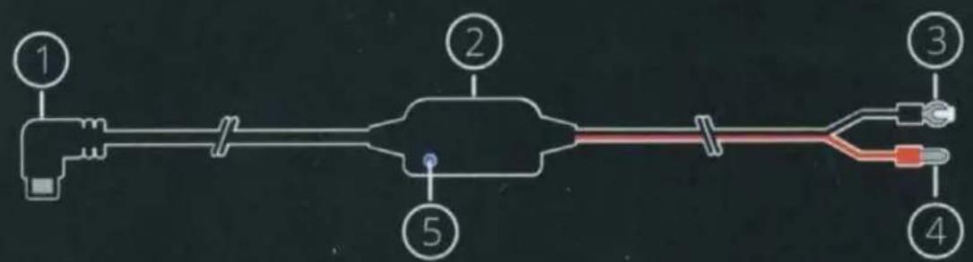
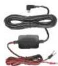
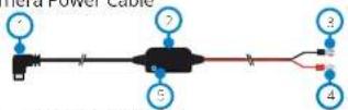
Camera Power Cable
text_image
Diagram of a multi-stage electrical or mechanical system with numbered components, likely for circuit analysis or measurement.① 5V Mini USB connector
② 12-24Vdc to 5Vdc regulator
③ Negative (-) spade connector
④ Positive (+) car power cable bullet connector
⑤ LED indicator
Fuse Tap Cables

text_image
⑨ ⑦ ⑧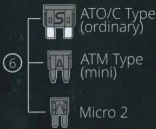
text_image
ATO/C Type (ordinary) ATM Type (mini) Micro 2⑥ ATO/C, ATM, & Micro 2 fuses. 2 Amp.
⑦ Supplied Amp fuse location
⑧ Original fuse location
⑨ Positive (+) fuse tap cable bullet connector
Note: For Micro (Low Profile Mini) Fuses, see item 1.3 overleaf.

text_image
2 Amp
natural_image
Green checkmark symbol on dark background (no text or numbers)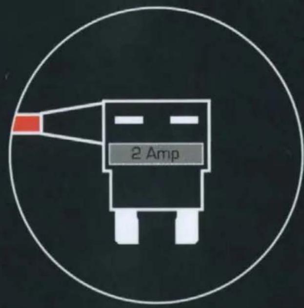
text_image
2 Amp
natural_image
Red X-shaped symbol on black background (no text or numbers)NOTE:
The supplied 2 Amp fuse MUST be placed in the uppermost socket, as shown above, in line with the red cable. The original fuse is to replaced in to the lower socket.
Failure to do so will change the protection of the original circuit within the vehicle. Whilst this will NOT cause any damage to the vehicle, the lower 2Amp fuse may blow.
Safety Notes:
- Perform the installation with the ignition in the OFF position.
- Do not strip any live wires.
- Correct electrical polarity and grounding is required for safe and proper installation.
- Only connect to a negative ground DC supply circuit.
- Not for installation to positive ground circuits.
Warnings:
- Failure to use the supplied installation parts and/or hardware will void the product warranty
- Failure to connect the product as instructed, may result in discharge of the vehicle battery.
- Failure to follow these safety precautions and instructions could result in damage to the product or vehicle, which will not be covered under the manufacturers warranty.
Installation
1 Connect the supplied 'Fuse Tap Cable' to the vehicle's fuse box.
1.1 Locate the fuse box within your vehicle. This is usually within the passenger compartment but it may be in the engine bay. Typically there will be a chart detailing the fuse layout within the fuse box, or this will be listed in the vehicle operating manual.
1.2 Select a fuse which is associated with a function within the vehicle which can only be used when the ignition is turned on, this is known as 'switched' power source. This could be the vehicles 'heated rear window', as an example. Mark down the position of this fuse carefully for future reference, remove the selected fuse from the fuse box.
Note: The rating of the 'original fuse' that is being removed is of no importance, however it is recommended that the maximum rating is no more than 20 Amps.
1.3 Select the required Fuse Tap Cable from the two supplied types. This depends on whether the original fuse was of the larger ATO/C or smaller ATM type. The 2 Amp fuse required to protect the Dash Cam is already installed within the Fuse Tap Cable and should NOT be changed. Insert the original fuse from the vehicle in to the available location upon the Fuse Tap Cable, this will be the 'original fuse location', as shown overleaf. Now insert the Fuse Tap Cable in to the fuse box, at the position where the original fuse was removed from, as noted in Item 1.2, overleaf.
Note: If the fuse removed from your vehicle is a Micro (low profile mini) fuse type, then you can still use the ATM (Mini) fuse tap cable. You will however need to source yourself another ATM (Mini) fuse, of the same rating as the fuse that you removed originally. Place the new ATM (Mini) fuse into the 'original fuse location'. At this stage, if you have a multi-meter, you can check for 12-24Vdc at the end of the Fuse Tap Cable. A voltage should only be present when the vehicle's ignition is turned on (or connected to a permanent live). There is also an LED on the regulator housing to indicate if the Fuse Tap Cable has been wired correctly (see next page).
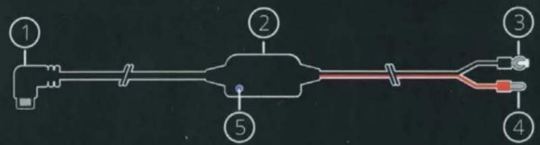
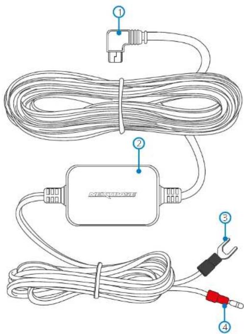
Camera Power Cable
text_image
Diagram of a mechanical or electrical device with numbered components and labeled parts① 5V Mini USB connector
② 12-24Vdc to 5Vdc regulator
③ Negative (-) spade connector
④ Positive (+) car power cable bullet connector
⑤ LED indicator
Fuse Tap Cables

text_image
⑨ ⑦ ⑧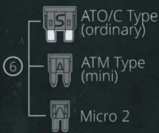
flowchart
graph TD
    A["ATO/C Type (ordinary)"] --> B["Micro 2"]
    C["ATM Type (mini)"] --> D["Micro 2"]
    E["⑥"] --> F["Micro 2"]
⑥ ATO/C, ATM, & Micro 2 fuses. 2 Amp.
⑦ Supplied Amp fuse location
⑧ Original fuse location
⑨ Positive (+) fuse tap cable bullet connector
Note: For Micro (Low Profile Mini) Fuses, see item 1.3 overleaf.
to loosen any trim and hide the cable as necessary. Make sure there is still sufficient cable available to connect to the Dash Cam, when installed correctly upon it's windscreen mount.
2.3 Continue to route the cable towards the fuse box. Once close to the fuse box, take the black wire (negative) from the Car Power Cable and find a suitable position to attach the spade connector to the vehicle bodywork. Normally a screw can be removed and refitted with the spade connector underneath. Take the red wire (positive) from the Car Power Cable and locate the red bullet connector at the end. This plugs directly in to the female bullet connector of the Fuse Tap Cable.
2.4 Tidy any excess cable using cable clips and secure the cable to a convenient location to prevent rattles. Replace any removed trim from the vehicle and the fuse box cover, as required.
2.5 A Ferrite Core is supplied with the Hardwire Kit. This can be used to suppress any interference which may be heard upon FM or DAB radio. Clip the Ferrite Core to the Camera Power Cable at a distance of approximately 20cm from the camera for best effect, if required.
Note: In the unlikely event that the installation of the Hardwire Kit should require drilling of holes, the installer MUST be sure that no vehicle components or other vital parts could be damaged by the drilling process. Check both sides of the area before drilling begins. De-burr any holes and remove any metal remnants. Install a rubber grommet into any cable passage holes, before passing cables through.
Should you experience any difficulties during installation please do not hesitate to contact our technical support team
support@nextbase.com
NEXTBASE Dash Cams
www.nextbase.com


text_image
NEXTBASE Dash Cams NEXTBASE Accessories User ManualNextbase Accessories
Your power, your way...
The Nextbase™ Accessories cover everything you might need for video storage, a second vehicle, or to protect your Dash Cam when not in use. The innovative Nextbase™ Module system also allows you to have a second view from your Dash Cam, capturing the road behind you or the interior of your vehicle for extra protection. These products are designed to enhance your recordings and help better cover you in the event of an incident, all with ease of use in mind.

Dash Cam
Carry Case
p. 03 p. 03
SD Cards & Go Packs

Cabin View Camera
p. 04/05

Night Vision
Cabin Cam
p. 04 / 05

Rear View Camera
p. 04/05
Rear Window Camera
p. 06 / 07

Polarising Filter
p. 08
Hardwire Kit
p.09/10
Nextbase™ Carry Case
The Carry Case is a soft case to safely transport your Nextbase Dash Cam.

natural_image
Line drawing of a backpack with a labeled tag (NEXTBASE) on the front cover, no other text or symbols present.Nextbase™ SD Cards
For best results, we recommend using our Nextbase™branced SD cards with your Dash Cam, available to purchase online from nextbase.com or your nearest retailer.
16GB 32GB 64GB 128GB
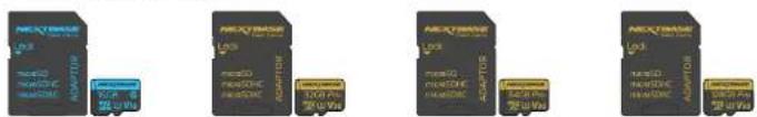
Approx 2 hours footage. Approx 4 hours footage. Approx 8 hours footage. Approx 16 hours footage.
We recommend formatting your SD Card every 2 weeks to ensure that there is enough space to record and store new footage. When formatting, protected files WLL be deleted. If you wish to keep these protected files, you must back then up externally, most commonly by saving files to a desktop computer, or another secure storage point.
To clear your SD card, go to the 'Format SD Card' function in your Desh Cam's Setup settings Menu and follow the instructions on screen.
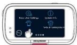
text_image
Knee Jock Stützinger System Info Data & Settings System


Nextbase™ Go Packs
You can purchase a Carry Case with an SD Card as part of the Nextbase. Go Pack to get you up and running quickly and smoothly. ^TM

natural_image
Two black leather covers with attached accessories, one featuring a logo and the other displaying a QR code (no visible text or symbols on covers)Rear View Cameras
Before attaching any Rear View Cameras, ensure that the Dash Cam is switched OFF. Do not turn the Dash Cam ON until the Rear View Camera is securely attached. When a Rear Cam is used with your Dash Cam, a UB SD Card is required.
Cabin View Camera
The Cabin View Camera is a compact accessory that nearly attaches to your Dash Cam. The wide 140° angle lens allows you to view and record the interior of your vehicle in addition to the road ahead, providing an extra level of security for you and your passengers.
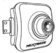
Suitable for


Night Vision Cabin View Camera
The Night Vision Cabin View Camera can record clearer night-time video than the Cabin View Camera (above). It records full colour video during daylight, and at night switches to recording infrared video, clearly capturing the interior of your vehicle.

Suitable for:


Rear View Camera
The Rear View Camera is a compact accessory that neatly attaches to your Dash Cam to allow you to view and record out of the rear of your vehicle in addition to the road ahead, making sure you're protected against tailgaters and rear-end impacts.
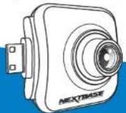
Suitable for

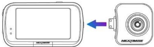
Installation and Positioning:
Simply plug the Rear View Camera into your Dash Cam using the socket on the right hand side, ensuring that the lens is facing backwards, into your vehicle.
text_image
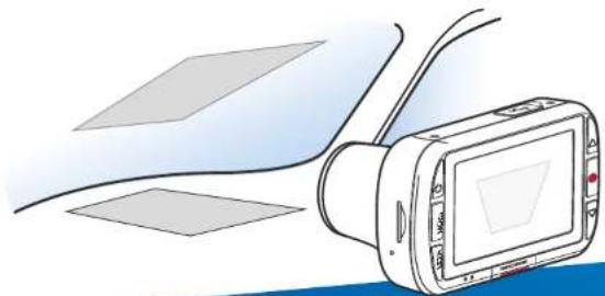
NEXTBASE NEXTBASEWhen adjusting the angle of the lens, to avoid damaging components in the cameras, use both hands to steady the Rear View Camera. Where possible, adjust the lens position on the Rear View Camera before attaching to your Dash Cam.

natural_image
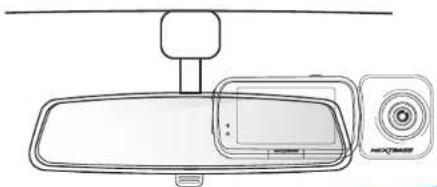
Line drawing of two hands assembling or adjusting a cylindrical device (no text or symbols present)Below is a suggested position for your Dash Cam with Rear View Camera attachment. Ensure that both the Dash Cam and Rear Facing Camera's lines of sight are unobstructed by in car objects, such as the rear view mirror.
natural_image
Line drawing of a rearview mirror and camera module (no text or symbols)Rear View Display and Screenshots
text_image
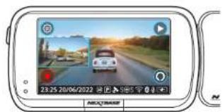
23:25 20/06/2022When the Dash Cam is turned on with a Rear View Camera connected, you will see a Picture in Picture (PiP) to the centre left of the screen, showing the attached camera's view.
natural_image
Illustration of a street scene with vehicles and buildings, no visible text or symbolsTapping on the PiP window opens the Rear View in full screen. Tapping again minimises the Rear View back down to PiP.
text_image
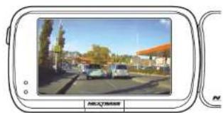
23:35 20/06/2022When 'Reversing Camera' is turned ON in the menu system, the full screen Rear View is flipped to mimic the rear view mirror.

text_image
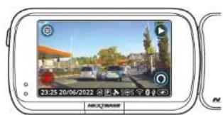
23:25 20/06/2022 ARCCUMBERScreen Capture: If a Rear Cam is attached, touch the centre of the Front Facing view (yellow dotted area, left) to take a photo. This will save 2 photos, one from the Front Facing camera, and one from the Rear Facing camera.
Resolutions:
The resolution of your Rear Cam is dependent on the resolution settings on your Dash Cam. These figures vary through the 322GW, 422GW, and 522GW; check the instruction manual of the relevant model for details regarding resolution settings.
Audio Recording:
With a Rear Camera attached the Dash Cam will record 2 separate video streams, one from the Front Facing camera, and one from the Rear Facing Camera; however, as the rear cameras do not have built-in microphones, audio is only recorded from the Dash Cam (i.e. Front Facing camera). This audio is applied to recordings from both the Front and Rear cameras.

natural_image
Line drawing of a digital camera with front and back views (no text or symbols)Rear Window Camera
Before attaching any Rear View Cameras, ensure that the Dash Cam is switched OFF. Do not turn the Dash Cam ON until the Rear View Camera is securely attached. When a Rear Cam is used with your Dash Cam, a UB SD Card is required.
The Rear Window Camera is an additional compact camera that affixes to the rear window of your vehicle, allowing you to record the road behind you as well as the road ahead, capturing everything from tailgaters to rear-end impacts.
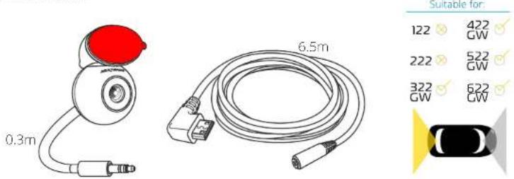
text_image
0.3m 6.5m Suitable for 122 422 GW 222 522 GW 322 622 GW CWConnect the Rear Window Camera to the lead, and the lead to the Dash Cam.

natural_image
Technical line drawings of two mechanical components with arrows indicating assembly or connection (no text or symbols present)Place the magnetic, adjustable mounting fixture (1) on top of the camera. The changeable angle (2) allows for the Rear Window Camera to be mounted on both slanted car windows, and vertical van windows. See next page for installation notes and instructions.

text_image
Diagram illustrating a three-step procedure for using a device to interact with a blue surface, labeled with steps ① and ②.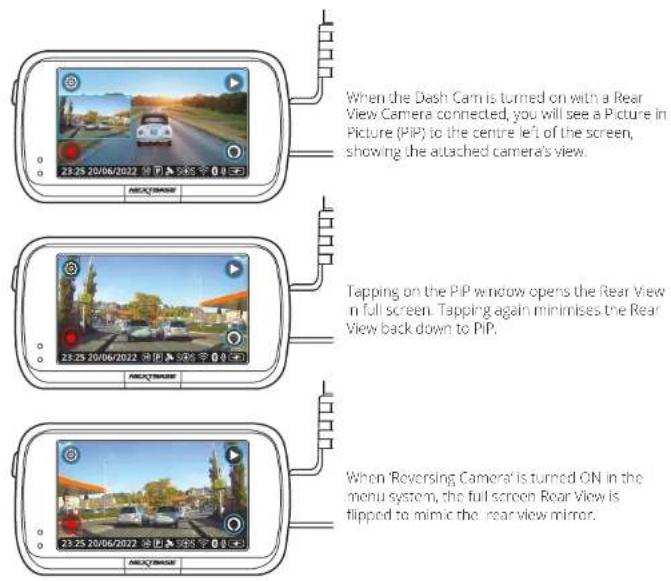
text_image
When the Dash Cam is turned on with a Rear View Camera connected, you will see a Picture in Picture (PIP) to the centre left of the screen, showing the attached camera's view. Tapping on the PiP window opens the rear View in full screen. Tapping again minimises the Rear View back down to PiP. When 'Reversing Camera' is turned ON in the menu system, the full screen Rear View is flipped to mimic the rear view mirror.When A Rear View Camera is attached, 4 files are produced per recording. As well as the standard High and Low Resolution Files (Forward Facing), there will also be High and Low Resolution Files (Rear Facing). The smaller file size of the low quality video means it is quicker to transfer and edit within the app.
Resolutions:
The resolution of your Rear Cam is dependent on the resolution settings on your Dash Cam. These figures vary through the 322GW, 422GW, and 522GW; check the instruction manual of the relevant model for details regarding resolution settings.
Audio Recording:
With a Rear Camera attached the Dash Cam will record 2 separate video streams, one from the Front Facing camera, and one from the Rear Facing Camera, however, as the rear cameras do not have built-in microphones, audio is only recorded from the Dash Cam (i.e. Front Facing camera). This audio is applied to recordings from both the Front and Rear cameras.
Rear Window Camera (continued)
Installation:
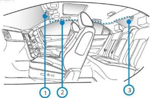
Make sure your Dash Cam is mounted securely on the windshield of your vehicle, in the position you use day to day. Connect the Rear Window Camera to the Dash Cam using the 6.5 m connecting cable, and run it through your vehicle to the rear window, stowing the cable within the headlining or the floor, using the Nextbase™ Cable Tidy Tool (Included with your Dash Cam) if necessary. The end of the cable should emerge at the rear of the vehicle, allowing you to connect and mount the Rear Window Camera to your window.
text_image
Diagram of car interior with numbered annotations pointing to specific compartments or features1 Dash Cam
2 Connector Cable
3 Rear Window Camera
Diagram is for illustration purposes only.

Please note, it is sometimes necessary to run the cable through the floor rather than the roof lining. Usually, this is due to the presence of airbags in the roof lining. If you are having the Rear Window Camera fitted by one of our retailers, they will install the Camera in the way most suitable for your vehicle. However the Rear Window Camera is installed: - It is important to keep the cable tidy so it is not a distraction. Make sure the boot can open with the Rear Window Camera attached.
Hiding the Cable:
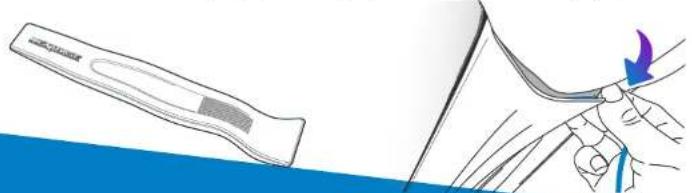
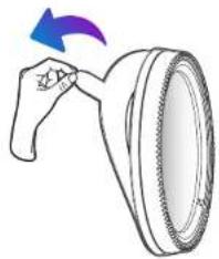
Make sure that hanging cables does not obstruct your view out of your rear window. Ensure that there are no kinks in the cable as you are stowing it. If necessary, use the cable tidy tool supplied with your Dash Cam; this can be used to help pry open the lining of your car (see illustration below, right).
natural_image
Illustration of a medical or surgical tool interacting with a clip, showing a blue arrow indicating direction (no text or symbols present)Installation Notes:

natural_image
Line drawing of a car front bumper with visible red X and green checkmark indicators (no text or symbols)Camera Placement:
It is advisable to place the rear racing camera within the wiper zone towards the top of your rear window in order to record the clearest possible image. Ensure that the view is not obstructed by heating grid lines.

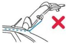
Opening the Boot:
Leave around 30-40cm of slack at the rear of the vehicle to ensure that there is enough cable to comfortably open the boot without dislodging the Rear Window Camera.

natural_image
Illustration of a hand holding a red object next to a device, with directional arrows indicating movement (no text or symbols)Apply to Rear Window:
When you have found a suitable area, with an unobstructed view and enough slack to allow the boot to open, remove the backing plastic from the magnetic mount fixture and carefully apply it to your rear window. When it is in place, you can adjust the positioning of the camera using the Dash Cam display to ensure you are capturing the intended area behind you. You may want to ask someone else to assist you in this part.
Polarising Filter/Reflection Free Lens
The Polarising Filter is designed to reduce the glare on your windscreen as seen through the Dash Cam, allowing you to record the road ahead clearly. In bright sunlight the filter will also enhance the colour and contrast levels to help capture important number plate details. The 522GW and 622GW Dash Cam mode already have a built-in polarising filter.

Suitable for:
122
[NO TEXT]
422 GW
222
1
522 GW
322 GW
[NO TEXT]
622 GW
Remove the adhesive layer on the back of the Polarising Filter, and apply the filter to the front of the Dash Cam lens, making sure that the text ("140° Wide Angle Lens") is at the top of the lens. Also ensure that you remove the protective layer over the lens before using your Dash Cam.

natural_image
Illustration of a hand holding a tire with a blue arrow indicating rotation (no text or symbols)
natural_image
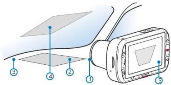
Technical line drawing of a mechanical component with two blue arrows indicating direction (no text or symbols)Adjusting the Polarising Filter:
The most effective way to set up your Polarising Filter (1) is to place a piece of plain white paper (2) on your dashboard (3) under the rear view mirror. With your camera turned ON you will see the reflection (4) of the paper in the LCD screen of the Dash Cam. Look at the reflection (4) on the windscreen through the Dash Cam display ( 1).5
text_image
Diagram showing a device with labeled components, including a screen and two rectangular panels with numbered indicators.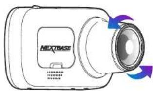
natural_image
Line drawing of a next-toe base camera with blue and purple arrows indicating rotation (no text or symbols)Gently rotate the front bezel to adjust the filter. Rotate the filter until the windscreen reflection is as hidden as possible on the Dash Cam display (see below).
Once the reflection can no longer be seen, operate the Dash Cam normally. Please note, it may not be possible to fully remove the reflection, but using the Polarising Filter will noticeably improve your video quality.
natural_image
Illustration of a handheld device with a screen and antenna, connected to a curved surface (no text or symbols visible)The above diagram is for illustration purposes only.

Do not place fingers on the glass lens of the filter. Do not adjust the filter while in control of the vehicle
Hardware Kit
For use with all Nextbase™ Dash Cam models. These instructions provide the necessary information to install the Dash Cam Hardware Kit properly and safely within your vehicle. Before beginning the installation process, please read these instructions carefully. It is recommended for normal journey video recording, the Hardware Kit is connected to a switched power supply. This means that power is supplied to the Dash Cam ONLY when the vehicle's ignition is turned on. A permanent live (un-switched) connection is only required when the Dash Cam is to be used when the vehicle is not in use, i.e. for surveillance purposes. The Dash Cam will operate normally until the vehicle's battery drops below the minimum voltage cut-off level; this minimum voltage cut-off is 11.0Vdc for a 12Vdc battery and 23.0Vdc for a 24Vdc battery. This protects the vehicle's battery.
If in any doubt, please consult a vehicle technician prior to starting installation.
Suitable for:
122
422 GW
222
522 GW
322 GW
622 GW
Safety Precautions:
Perform the installation with the ignition in the OFF position.
- Do not strip any live wires.
- Correct electrical polarity and grounding is
required for safe and proper installation. - Only connect to a negative ground DC supply circuit.
- Not for installation to positive ground circuits.
Warnings:
- Failure to use the supplied installation parts and/or hardware will void the product warranty. - Failure to connect the product as instructed may result in discharge of the vehicle battery.
- Failure to follow these safety precautions and instructions could result in damage to the product and/or vehicle, which will not be covered under the product warranty or the manufacturer's warranty.
Camera Power Cable

5V Mini USB connector
12-24Vdc to 5Vdc regulator
Negative (-) soade connector
Positive (+) car power cable bullet connector
LED indicator
Fuse Tap Cables


ATO/C & ATM fuses. 2 Amp
Supplied Amp fuse location
Original fuse location
Positive (+) fuse tap cable bullet connector
Note: For Micro (Low Profile Mini), Fuses, see item 1.3 overleaf.
text_image
① ② ③ ④Hardware Kit (cont.)
Installation
① Connect the supplied 'Fuse Tap Cable' to the vehicle's fuse box.
① Locate the fuse box within your vehicle. This is usually within the passenger compartment but it may be in the engine bay. Typically there will be a chart detailing the fuse layout within the fuse box, or this will be listed in the vehicle operating manual.
Select a fuse which is associated with a function within the vehicle which can only be used when the ignition is turned on, this is known as 'switched' power source. This could be the vehicles 'heated rear window', as an example. Mark down the position of this fuse carefully for future reference, remove the selected fuse from the fuse box.
Note: The rating of the 'original fuse' that is being removed is of no importance, however it is recommended that the maximum rating is no more than 20 Amps.
⑬ Select the required Fuse Tap Cable from the two supplied types. This depends on whether the original fuse was of the larger ATO/C or smaller ATM type. The 2 Amp fuse required to protect the Dash Cam is already installed within the Fuse Tap Cable and should NOT be changed. Insert the original fuse from the vehicle in to the available location upon the Fuse Tap Cable, this will be the 'original fuse location', as shown overleaf. Now insert the Fuse Tap Cable in to the fuse box, at the position where the original fuse was removed from, as notes in item 1.2 above.
Note: If the fuse removed from your vehicle is a Micro (low profile mini) fuse type, then you can still use the ATM (Mini) fuse tap cable. You will however need to source yourself another ATM (Mini) fuse, of the same rating as the fuse that you removed originally. Place the new ATM (Mini) fuse into the 'original fuse location'. At this stage, if you have a multi-meter, you can check for 12-24Vdc at the end of the Fuse Tap Cable. A voltage should only be present when the vehicle's ignition is turned on (or connected to a permanent live). There is an LED on the regulator housing to indicate if the Fuse Tap Cable has been wired correctly (see below).
LED Indicator
If there is no power to the Hardwire Kit the LED will not be turned on.
Once power is flowing to the Hardware Kit, the Led will turn on. If there is no Dash Cam connected, it will flash
If there is a Dash Cam connected, the LED will remain on.

No LED
No power OR battery protected
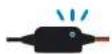
Flashing LED
Power established, NO
Dash Cam connected
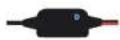
Solid LED
Power established Dash Cam connected
2 Installing the Camera Power Cable
3.1 Installation of the camera power cable needs careful planning for the cable run and the final position of the Dash Cam within the vehicle. See the Dash Cam manual for optimum camera position. Study the vehicle for the most appropriate cable run towards the fuse box, especially if this requires passing through the bulkhead in to the engine bay.
Starting from the Dash Cam end of the cable (with the mini USB plug) tuck the cable under the vehicle headlining, the 'A' pest trim and side panel trim until the cable exits towards the footwell. Use a Cable Ticy Tool supplied with your Series 2 Dash Cam to loosen any trim and hide the cable as necessary. Make sure there is still sufficient cable available to connect to the Dash Cam, when installed correctly upon it's windscreen mount.
Continue to route the cable towards the fuse box. Once close to the fuse box, take the black wire (negative) from the Car Power Cable and find a suitable position to attach the spade connector to the vehicle bodywork. Normally a screw can be removed and refitted with the spade connector underneath. Take the red wire (positive) from the Car Power Cable and locate the red bullet connector at the end. This plugs directly in to the female bullet connector of the Fuse Tap Cable.
Tidy any excess cable using cable clips and secure the cable to a convenient location to prevent rattles. Replace any removed trim from the vehicle and the fuse box cover, as required.
A Ferrite Core is supplied with the Hardwire Kil. This can be used to suppress any interference which may be heard upon FM or DAB radio. Clip the Ferrite Core to the Camera Power Cable at a distance of approximately 20cm from the camera for best effect, if required.
Note: In the unlikely event that the installation of the Hardwire Kit should require drilling of holes, the installer MUST be sure that no vehicle components or other vital parts could be damaged by the drilling process. Check both sides of the area before drilling begins. De burn any holes and remove any metal remnants. Install a rubber grommet into any cable passage holes, before passing cables through.
Should you experience any difficulties during installation please do not hesitate to contact our technical support team
support@nextbase.com
Accessory Model Compatibility


| 122 | 222 | 322GW | 422GW | 522GW | 622GW | |
| Carry Case | Yes | Yes | Yes | Yes | Yes | Yes |
| Nextbase Rear Cams- Cabin View Camera- Rear View Camera- Night Vision Cabin View Camera- Rear Window Camera | No | No | Yes - Front 1080pRear 720p | Yes - Front 1440p/1080pRear 720p/1080p | Yes - Front 1440p/1080pRear 720p/1080p | Yes - Front 1440p/1080pRear 720p/1080p |
| Rear Window Camera Bracket | No | No | Yes | Yes | Yes | Yes |
| Polarising Filter | Yes | Yes | Yes | Yes | Comes built-in | Comes built-in |
| Hardwire Kit | Yes | Yes | Yes | Yes | Yes | Yes |
| SD Cards | Yes | Yes | Yes | Yes | Yes | Yes |

text_image
Our eyes on the road, you mind on the journey.Our eyes on the road, you mind on the journey.
NEXTBASE Dash Cams


www.nextbase.com


NBACCESS-ENG-R7