
KX-TG8511SL - Cordless phone Black Box - Free user manual and instructions
Find the device manual for free KX-TG8511SL Black Box in PDF.

| Product Type | DKM Series TC KM Switch (KVM Switch) |
| Brand | Black Box |
| Model | KX-TG8511SL (as labeled, but device is TC KM Switch) |
| Dimensions (Switch) | 1.7"H x 8.2"W x 5.6"D (4.2 x 20.9 x 14.3 cm) |
| Shipping Weight | 1.3 lb (0.6 kg) |
| Power Supply | 5 VDC, max 500 mA (4-port) to 700 mA (8-port) |
| Operating Temperature | 41 to 113°F (5 to 45°C) |
| Storage Temperature | -13 to +140°F (-25 to +60°C) |
| Relative Humidity | Max 80% non-condensing |
| Interfaces | USB-HID, RJ-10/4P4C, Mini USB (service), USB Type A/B |
| Supported Peripherals | Keyboards, mice, touch screens, barcode scanners (USB-HID) |
| Number of Ports | 4 or 8 (depending on model) |
| MTBF | 357,000 to 487,000 POH (depending on model) |
| Package Contents | Switch, power supply, power cord, CD-ROM with manual, USB cables (quantity varies) |
| Safety Instructions | Use in dry indoor environment, do not block vents, use grounded outlets |
| Hotkey Command Mode | Double-tap Scroll Lock (default) to enter, Esc to exit |
| Switching Methods | Keyboard hotkeys, mouse panning (multi-screen), external button |
| Firmware Update | Via mini USB service port, copy firmware files to flash drive |
| Regulatory Compliance | FCC Class A, CE, RoHS 2, WEEE |
| Warranty & Support | Technical support 24/7 at 877-877-2269 |
Frequently Asked Questions - KX-TG8511SL Black Box
User questions about KX-TG8511SL Black Box
0 question about this device. Answer the ones you know or ask your own.
Ask a new question about this device
Download the instructions for your Cordless phone in PDF format for free! Find your manual KX-TG8511SL - Black Box and take your electronic device back in hand. On this page are published all the documents necessary for the use of your device. KX-TG8511SL by Black Box.
USER MANUAL KX-TG8511SL Black Box
SAFETY INSTRUCTIONS....4
1. SPECIFICATIONS....5
1.1 Interfaces .... 5
1.1.1 USB-HID 5
1.1.2 RJ-10/4P4C 5
1.2 Supported Peripherals 6
1.2.1 USB-HID Devices 6
1.3 Connector Pinouts ....6
1.3.1 USB Type B Connector 6
1.3.2 USB Type A Connector 6
1.3.3 Mini USB Type B Connector 7
1.3.4 RJ-10/4P4C Connector 7
1.3.5 Power Supply Connector 7
1.4 Power Supply 7
1.5 Environmental Conditions 8
1.6 Dimensions 8
1.7 Shipping Weight....8
1.8 MTBF 8
2. DESCRIPTION....9
2.1 Application 9
2.2 System Overview....9
2.3 Product Range....10
2.4 Device Views....11
2.4.1 DKM Series, 4-Port TC KM Switch with (2) HID Ports (ACX1004A-HID2)....11
2.4.2 DKM Series, 8-Port TC KM Switch with (2) HID Ports (ACX1008A-HID2)....12
2.4.3 DKM Series, 4-Port TC KM Switch with (4) HID Ports (ACX1004A-HID4)....13
2.4.4 DKM Series, 4-Port TC KM Switch with (2) HID Ports and (2) USB 2.0 Ports (ACX1004A-U23) 14
2.5 Status LEDs 15
3. INSTALLATION 17
3.1 Package Contents .... 17
3.2 System Setup 17
3.3 Example Applications....18
4. CONFIGURATION ...... 20
4.1 Command Mode....20
4.2 Configuration of Multi-Screen Control....21
4.3 External Display (optional) 22
4.4 External Control (optional) 22
4.5 Firmware Update....22
TABLE OF CONTENTS
NEED HELP?
LEAVE THE TECH TO US
LIVE 24/7
TECHNICAL
SUPPORT
1.87 7.877.2269
- OPERATION....23
5.1 Switching a Source....23
5.1.1 Switching via Keyboard 23
5.1.2 Switching via Mouse (Panning) 23
5.1.3 External Switching (optional) 24
- TROUBLESHOOTING....25
6.1 USB-HID....25
- TECHNICAL SUPPORT 26
7.1 Support Checklist 26
7.2 Shipping Checklist....26
APPENDIX A. REGULATORY INFORMATION....27
A.1 FCC Statement 27
A.2 NOM Statement 28
A.3 CE Declaration Of Conformity 29
A.4 WEEE....29
A.5 RoHS/RoHS2....29
APPENDIX B. GLOSSARY 30
DISCLAIMER/TRADEMARKS 31
Disclaimer 31
Trademarks Used in this Manual....31
SAFETY INSTRUCTIONS
NEED HELP?
LEAVE THE TECH TO US
LIVE 24/7
TECHNICAL
SUPPORT
1.87 7.877.2269
SAFETY INSTRUCTIONS
To ensure reliable and safe long-term operation of your DKM Series TC KM Switch please note the following guidelines:
- Only use in dry, indoor environments.
- Only use the device according to this User Manual. Failure to follow these procedures could cause damage to the equipment or injury to the user or installer.
- The DKM Series TC KM Switch and the power supply units can get warm. Do not install components in an enclosed space without any airflow.
- Do not place the power supply directly on top of the device.
- Do not obscure ventilation holes.
Only use power supplies originally supplied with the product or manufacturer-approved replacements. Do not use a power supply if it appears to be defective or has a damaged chassis.
Connect all power supplies to grounded outlets. In each case, make sure that the ground connection is maintained from the outlet socket through to the power supply's AC power input. - Do not connect the link interface to any other equipment, particularly network or telecommunications equipment.
Take any required ESD precautions.
CAUTION: To disconnect the device completely from the electric circuit, remove all power cables.
- Do not attempt to open or repair a power supply unit.
- Do not attempt to open or repair the DKM Series TC KM Switch. There are no user-serviceable parts inside.
- Contact Black Box Technical Support at 877-877-2269 or info@blackbox.com if there is a fault.
1.1 INTERFACES
1.1.1 USB-HID
Our devices with USB-HID interface support a maximum of two devices with USB-HID protocol. Each USB-HID port provides a maximum current of 100 mA.
KEYBOARD
Compatible with most USB keyboards. Certain keyboards with additional functions may require custom firmware to operate. Keyboards with an integral USB Hub (Mac keyboards e.g.) are also supported.
MOUSE
Compatible with most 2-button, 3-button and scroll mice.
OTHER USB-HID DEVICES
The proprietary USB emulation also supports certain other USB-HID devices, such as specific touch screens, graphic tablets, barcode scanners or special keyboards. Support cannot be guaranteed, however, for every USB-HID device. Only two USB-HID devices are supported concurrently, such as keyboard and mouse or keyboard and touch screen. A hub is allowed, but it does not increase the number of HID devices allowed.
To support other USB “non-HID” devices, such as scanners, web cams or memory devices, choose our devices with transparent USB support.
1.1.2 RJ-10/4P4C
This interface is used to establish a customer-specific communication with the TC KM Switch.
EXTERNAL STATUS LED
To control an external LED to indicate the status of a port:
Connect the anode of the LED to pin 1 and the cathode to pin 2. Use a suitable series resistor that you connect in series. The interface supplies 3.3 V output voltage with 15 mA max.
EXTERNAL BUTTON
To control a port by an external button, use an NC (normally closed) contact as a switch. This contact has to short-circuit pin 3 and pin 4 to operate.
1.2 SUPPORTED PERIPHERALS
1.2.1 USB-HID DEVICES
Our The TC KM Switch will support most USB-HID devices, including the vast majority of keyboards and mice currently on the market. Many other kinds of HID devices such as bar-code scanners and touch screens may also be compatible.
It is not possible to guarantee support for all available USB-HID devices. In certain cases, custom firmware may be required.
USB-HID (and other) devices that are not supported as standard will normally operate with our devices featuring transparent USB support.
NOTE: Concurrent operation of more than two USB-HID devices is not possible even if you use a USB hub.
1.3 CONNECTOR PINOUTS
1.3.1 USB TYPE B CONNECTOR
TABLE 1-1. USB TYPE B CONNECTOR PINOUTS
| PICTURE PIN SIGNAL COLOR | |||
 | 1 VCC (+5 VDC) Red | ||
| 2 Data - White | |||
| 3 Data + Green | |||
| 4 | GND | Black | |
1.3.2 USB TYPE A CONNECTOR
TABLE 1-2. USB TYPE A CONNECTOR PINOUTS
| PICTURE | PIN SIGNAL COLOR | ||
| 1 2 3 4 | 1 VCC (+5 VDC) Red | ||
| 2 Data - White | |||
| 3 Data + Green | |||
| 4 | GND | Black | |
CHAPTER 1: SPECIFICATIONS
NEED HELP? LEAVE THE TECH TO US
LIVE 24/7 TECHNICAL SUPPORT
1.87 7.877.2269
1.3.3 MINI USB TYPE B CONNECTOR
TABLE 1-3. MINI USB TYPE B CONNECTOR PINOUTS
| PICTURE PIN SIGNAL COLOR | |||
 | 1 VCC (+5 VDC) Red | ||
| 2 Data - White | |||
| 3 Data + Green | |||
| 4 Not connected - | |||
| 5 | GND | Black | |
1.3.4 RJ-10/4P4C CONNECTOR
TABLE 1-4. RJ-10/4P4C CONNECTOR PINOUTS
| PICTURE | PIN SIGNAL | |
| 1 A | 1 LED + | |
 | 2 LED - | |
| 3 Dry Contact | ||
| 4 | GND |
1.3.5 POWER SUPPLY CONNECTOR
TABLE 1-5. POWER SUPPLY CONNECTOR PINOUTS
| PICTURE | PIN SIGNAL | |
| 5VDC | Inside | VCC (+5 VDC) |
 | Outside | GND |
1.4 POWER SUPPLY
TABLE 1-6. POWER SUPPLY SPECIFICATIONS
| SPECIFICATION | DESCRIPTION |
| Voltage | 5 VDC |
| Power Requirement | ACX1004A-HID2: max. 500 mA;ACX1008A-HID2: max. 700 mA;ACX1004A-HID4: max. 700 mA |
1.5 ENVIRONMENTAL CONDITIONS
TABLE 1-7. ENVIRONMENTAL SPECIFICATIONS
| SPECIFICATION DESCRIPTION |
| Operating Temperature 41 to 113° F (5 to 45° C) |
| Storage Temperature -13 to +140° F (-25 to +60° C) |
| Relative Humidity Max. 80% non-condensing |
1.6 DIMENSIONS
TABLE 1-8. DIMENSIONS SPECIFICATIONS
| SPECIFICATION DESCRIPTION | |
| Switch Dimensions 1.7"H x 8.2"W x 5.6"D (4.2 x 20.9 x 14.3 cm) | |
| Shipping Box Dimensions | 5.1"H x 11.0"W x 7.1"D (13 x 28 x 18 cm) |
1.7 SHIPPING WEIGHT
TABLE 1-9. SHIPPING WEIGHT SPECIFICATIONS
| SPECIFICATION DESCRIPTION | |
| Shipping Weight | 1.3 lb. (0.6 kg) |
1.8 MTBF
The following table contains the mean time between failure (MTBF) in power-on hours (POH). The estimate is based on the FIT rates of the parts included. FIT rates are based on normalized environmental conditions of T = 60° C and activation energy (Ea) of 0.7 eV. Calculations are based on 90% confidence limit.
We estimate that inside the housing, temperature will be 15° C higher than the ambient temperature. Therefore, the MTBF calculation refers to an ambient temperature of 45° C. The humidity is limited to 60%.
TABLE 1-10. MTBF SPECIFICATIONS
| SWITCH PRODUCT CODE | MTBF |
| ACX1004A-HID2 | 487,000 POH |
| ACX1008A-HID2 | 361,000 POH |
| ACX1004A-HID4 | 357,000 POH |
| ACX1004A-U23 | 468,000 POH |
CHAPTER 2: DESCRIPTION
2.1 APPLICATION
The DKM Series TC KM Switch is used to communicate between several sources (computer, CPU, KVM Extender CON Units) and several monitors with one keyboard and mouse set only.
The DKM Series TC KM Switch is especially suitable for use with KVM switches and KVM extenders in the Black Box family.
2.2 SYSTEM OVERVIEW
The DKM Series TC KM Switch is connected to sources (computer, CPU, KVM extender CON Units) using the cables supplied. Keyboard and mouse are connected to the device.
![graph TD A["Computer 1"] --> D["Server"] B["Computer 2"] --> D C["Computer 3"] --> D D --> E["Server"] E --> F["Terminal"] style A fill:#ccc,stroke:#333 style B fill:#ccc,stroke:#333 style C fill:#ccc,stroke:#333 style E fill:#999,stroke:#333 style F fill:#ccc,stroke:#333](/content/2026/06/1212577/images/90fd2595835523b084ef714efd4e15cd74430e14e9790b224361484e9aeca9c7.jpg)
FIGURE 2-1. TYPICAL APPLICATION
TABLE 2-1. COMPONENTS IN A TYPICAL APPLICATION
| NUMBER IN FIGURE 2-1 DESCRIPTION |
| 1 Sources (computer, CPU, KVM Extender CON Units) |
| 2 TC KM Switch |
| 3 Keyboard, mouse |
NOTE: See Section 3.3 in this manual for installation examples.
2.3 PRODUCT RANGE
TABLE 2-2. AVAILABLE SWITCH MODELS
| PRODUCT CODE DESCRIPTION | |
| ACX1004A-HID2 TC KM Switch 4 Port | |
| ACX1008A-HID2 TC KM Switch 8 Port | |
| ACX1004A-HID4 TC KM Switch for parallel switching of 2x4 ports | |
| ACX1004A-U23 | TC KM Switch with 4 ports USB-HID and 4 ports USB 2.0 |
2.4 DEVICE VIEWS
2.4.1 ACX1004A-HID2

FIGURE 2-2. REAR VIEW OF THE ACX1004A-HID
TABLE 2-3. ACX1004A-HID2 COMPONENTS
| NUMBER IN FIGURE 2-2 DESCRIPTION | |
| 1 | Connect to RJ-10/4P4C (Port 1) |
| 2 | To CPU 1: USB-HID |
| 3 | Connect to RJ-10/4P4C (Port 2) |
| 4 | To CPU 2: USB-HID |
| 5 | Connect to RJ-10/4P4C (Port 3) |
| 6 | To CPU 3: USB-HID |
| 7 | Connect to RJ-10/4P4C (Port 4) |
| 8 | To CPU 4: USB-HID |
| 9 | Connect to USB-HID devices 1 |
| 10 | Connect to USB-HID devices 2 |
| 11 | Service port |
| 12 | Connect to 5-VDC power supply |
2.4.2 ACX1008A-HID2

FIGURE 2-3. REAR VIEW OF THE ACX1008A-HID2
TABLE 2-4. ACX1008A-HID2 COMPONENTS
| NUMBER IN FIGURE 2-3 DESCRIPTION | |
| 1 | Connect to RJ-10/4P4C (Port 1) |
| 2 | To CPU 1: USB-HID |
| 3 | Connect to RJ-10/4P4C (Port 2) |
| 4 | To CPU 2: USB-HID |
| 5 | Connect to RJ-10/4P4C (Port 3) |
| 6 | To CPU 3: USB-HID |
| 7 | Connect to RJ-10/4P4C (Port 4) |
| 8 | To CPU 4: USB-HID |
| 9 | Connect to USB-HID devices 1 |
| 10 | Connect to USB-HID devices 2 |
| 11 | Service port |
| 12 | Connect to 5-VDC power supply |
| 13 | Connect to RJ-10/4P4C (Port 5) |
| 14 | To CPU 5: USB-HID |
| 15 | Connect to RJ-10/4P4C (Port 6) |
| 16 | To CPU 6: USB-HID |
| 17 | Connect to RJ-10/4P4C (Port 7) |
| 18 | To CPU 7: USB-HID |
| 19 | Connect to RJ-10/4P4C (Port 8) |
| 20 | To CPU 8: USB-HID |
2.4.3 ACX1004A-HID4

FIGURE 2-4. REAR VIEW OF THE ACX1004A-HID4
TABLE 2-5. ACX1004A-HID4 COMPONENTS
| NUMBER IN FIGURE 2-4 DESCRIPTION | |
| 1 | Connect to RJ-10/4P4C (Port 1) |
| 2 | To CPU 1.1: USB-HID |
| 3 | Connect to RJ-10/4P4C (Port 2) |
| 4 | To CPU 2.1: USB-HID |
| 5 | Connect to RJ-10/4P4C (Port 3) |
| 6 | To CPU 3.1: USB-HID |
| 7 | Connect to RJ-10/4P4C (Port 4) |
| 8 | To CPU 4.1: USB-HID |
| 9 | Connect to USB-HID devices 1 |
| 10 | Connect to USB-HID devices 2 |
| 11 | Service port |
| 12 | Connect to 5-VDC power supply |
| 13 | Connect to RJ-10/4P4C (Port 5) |
| 14 | To CPU 1.2: USB-HID |
| 15 | Connect to RJ-10/4P4C (Port 6) |
| 16 | To CPU 2.2: USB-HID |
| 17 | Connect to RJ-10/4P4C (Port 7) |
| 18 | To CPU 3.2: USB-HID |
| 19 | Connect to RJ-10/4P4C (Port 8) |
| 20 | To CPU 4.2: USB-HID |
| 21 | Connect to USB-HID devices 3 |
| 22 | Connect to USB-HID devices 4 |
NOTE: USB-B connectors 1.2–4.2 must be connected to additional USB-HID modules on the extender in order to allow parallel switching with USB-B connectors 1.1–4.1.
:
2.4.4 ACX1004A-U23
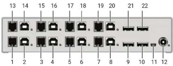
FIGURE 2-5. REAR VIEW OF THE ACX1004A-U23
TABLE 2-6. ACX1004A-U23 COMPONENTS
| NUMBER IN FIGURE 2-5 DESCRIPTION | |
| 1 | Connect to RJ-10/4P4C (Port 1) |
| 2 | To CPU 1.1: USB-HID |
| 3 | Connect to RJ-10/4P4C (Port 2) |
| 4 | To CPU 2.1: USB-HID |
| 5 | Connect to RJ-10/4P4C (Port 3) |
| 6 | To CPU 3.1: USB-HID |
| 7 | Connect to RJ-10/4P4C (Port 4) |
| 8 | To CPU 4.1: USB-HID |
| 9 | Connect to USB-HID devices 1 |
| 10 | Connect to USB-HID devices 2 |
| 11 | Service port |
| 12 | Connect to 5-VDC power supply |
| 13 | Connect to RJ-10/4P4C (Port 5) |
| 14 | To CPU 1.2: USB 2.0 |
| 15 | Connect to RJ-10/4P4C (Port 6) |
| 16 | To CPU 2.2: USB 2.0 |
| 17 | Connect to RJ-10/4P4C (Port 7) |
| 18 | To CPU 3.2: USB 2.0 |
| 19 | Connect to RJ-10/4P4C (Port 8) |
| 20 | To CPU 4.2: USB 2.0 |
| 21 | Connect to USB 2.0 devices 3 |
| 22 | Connect to USB 2.0 devices 4 |
NOTE: USB-B connectors 1.2–4.2 must be connected to additional USB 2.0 embedded modules.
CHAPTER 2: DESCRIPTION
NEED HELP? LEAVE THE TECH TO US
LIVE 24/7 TECHNICAL SUPPORT
1.87 7.877.2269
2.5 STATUS LEDS
The TC KM Switch is fitted with a multi-color LED on both sides that indicates connection status.
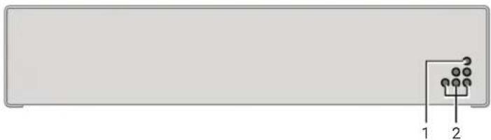
FIGURE 2-6. LEDS ON THE FRONT PANEL OF THE SWITCH
TABLE 2-7. STATUS LEDS ON THE FRONT PANEL
| NUMBER IN FIGURE 2-6 LED | STATUS DESCRIPTION | |
| 1 | Status (green) | Off Device not ready |
| On Device ready | ||
| 2 | Power (red) | Off Power supply not available |
| On Power supply available | ||
CHAPTER 2: DESCRIPTION
NEED HELP?
LEAVE THE TECH TO US
LIVE 24/7
TECHNICAL
SUPPORT
1.87 7.877.2269

FIGURE 2-7. LEDS ON THE BACK PANEL OF THE SWITCH
TABLE 2-8. STATUS LEDS ON THE BACK PANEL
| NUMBER IN FIGURE 2-7 LED | STATUS DESCRIPTION | |
| 1 | USB Status CPU 1 (green) | Off No connection to CPU 1 |
| On Connection to CPU 1 | ||
| 2 | USB Status CPU 2 (green) | Off No connection to CPU 2 |
| On Connection to CPU 2 | ||
| 3 | USB Status CPU 3 (green) | Off No connection to CPU 3 |
| On Connection to CPU 3 | ||
| 4 | USB Status CPU 4 (green) | Off No connection to CPU 4 |
| On Connection to CPU 4 | ||
| 5 | Power (red) | Off Device not ready |
| On Device ready | ||
| 6 | USB Status CPU 5 (green) | Off No connection to CPU 5 |
| On Connection to CPU 5 | ||
| 7 | USB Status CPU 6 (green) | Off No connection to CPU 6 |
| On Connection to CPU 6 | ||
| 8 | USB Status CPU 7 (green) | Off No connection to CPU 7 |
| On Connection to CPU 7 | ||
| 9 | USB Status CPU 8 (green) | Off No connection to CPU 8 |
| On Connection to CPU 8 | ||
3.1 PACKAGE CONTENTS
Your extender package contains the following items:
DKM Series TC KM Switch
- External power supply
Power cord
- CD-ROM with user manual
◆ (4) USB cables (1.8-m, Type A to Type B)
Additional items included in package for ACX1008A-HID2/ACX1004A-HID4/ACX1004A-U23:
◆ (4) USB cables (1.8-m, Type A to Type B)
If anything is missing or damaged, contact Black Box Technical Support at 877-877-2269 or info@blackbox.com.
3.2 SYSTEM SETUP
NOTE: For first-time users, we recommend that you set up the system with the CPU Unit and the CON Unit in the same room as a test setup. This will allow you to identify and solve any cabling problems, and experiment with your system more conveniently.
SETUP STEPS:
- Switch off all devices.
- Connect the USB cables to the CPUs (CON units) and to the TC KM Switch.
- Connect mouse and keyboard to the TC KM Switch.
- Connect the 5-VDC power supply to the TC KM Switch.
- Power up the system.
When powering up the TC KM Switch, a boot process will be enabled. The duration depends upon the size of the TC KM Switch (4 port version: 30 seconds, 8 port version: 50 seconds).
The boot process must complete before you can use the TC KM Switch and keyboard and mouse will be enabled.
3.3 EXAMPLE APPLICATIONS
This section illustrates typical installations of the TC KM Switch.
![graph TD A["Computer 1"] --> B["Server"] C["Computer 2"] --> D["Server"] E["Computer 3"] --> F["Server"] G["Computer 4"] --> H["Server"] B --> I["Central Server"] D --> I F --> I H --> I I --> J["Computer"] style I fill:#99ccff,stroke:#333](/content/2026/06/1212577/images/fe3560141d6f6262949c58f4b4280eebe8055d718aeb3ca003284c1a7f5c5686.jpg)
FIGURE 3-1. DIRECT CPU CONNECTION
TABLE 3-1. TC KM SWITCH (DIRECT CPU CONNECTION)
| NUMBER IN FIGURE 3-1 DESCRIPTION |
| 1 Source (computer, CPU) |
| 2 Switch button |
| 3 TC KM Switch |
| 4 Keyboard, mouse |
CHAPTER 3: INSTALLATION
NEED HELP?
LEAVE THE TECH TO US
LIVE 24/7
TECHNICAL
SUPPORT
1.87 7.877.2269
![graph TD A["1"] --> B["2"] B --> C["3"] C --> D["4"] D --> E["5"] F["Computer"] --> B G["Mouse"] --> D](/content/2026/06/1212577/images/6302987bf2633bd95a6e29949821f1d62bf56930cc6845bd7a27033a9e23fddc.jpg)
FIGURE 3-2. USING THE TC KM SWITCH WITH A BLACK BOX KVM SWITCH
TABLE 3-2. TC KM SWITCH (IN COMBINATION WITH BLACK BOX KVM SWITCH)
| NUMBER IN FIGURE 3-2 DESCRIPTION |
| 1 Black Box KVM Switch |
| 2 CON Units |
| 3 Monitor LEDs |
| 4 TC KM Switch |
| 5 Keyboard, mouse |
4.1 COMMAND MODE
The TC KM Switch has a Command Mode that allows several functions via keyboard command during normal use.
To enter Command Mode, use a hotkey sequence and to exit Command Mode, press
If no keyboard command is executed within 10 seconds after activating Command Mode, it will be automatically deactivated.
The following table lists the keyboard commands to enter and to exit Command Mode and to change the hotkey sequence.
TABLE 4-1. KEYBOARD COMMANDS
| FUNCTION KEYBOARD COMMAND | |
| Enter Command Mode (default) 2x(or hotkey) | |
| Exit Command Mode | |
| Change hotkey sequence | ,,,Until 2011-30-09:+, |
2x
The hotkey sequence to enter Command Mode can be changed. The following table lists the Hotkey Codes for the available key sequences.
TABLE 4-2. HOTKEY CODES
| HOTKEY CODE HOTKEY |
| 0 Freely selectable (2012-01-12) |
| 2 2x |
| 3 2x |
| 4 2x |
| 5 2x |
| 6 2x |
| 7 2x |
| 8 2x |
NOTE: In a KVM switch configuration, choose different hotkeys for the KVM Extender and the Black Box TC KM Switch.
Set freely selectable Hotkey (exemplary)
To set a freely selectable hotkey (e.g. 2x
Reset Hotkey
To set a hotkey back to the default settings of the extender, press the key combination within 5 seconds after switching on the CON unit or plugging in a keyboard.
CHAPTER 4: CONFIGURATION
4.2 CONFIGURATION OF MULTI-SCREEN CONTROL
The TC KM Switch can be flexibly configured for the use of Multi-Screen Control via Tera tool, so the possibility of switching via mouse.
For a configuration proceed as follows:
-
Execute the DKM Java Utility on your computer.
-
Select "Extras > KM-Switch MSC Configurator" in the menu bar.
-
Connect the TC KM Switch via a Mini-USB cable to your computer.
-
Press the button "Search KM-Switch."
-
Select your TC KM Switch from the list and press the Next > button.
-
Select the requested layout in the field "Arrangement" or select "Free Layout" for a flexible layout.
-
If you have selected "Free Layout," move the requested monitors from the field "Available Screens" into the grid and arrange them according to your requirements. The monitors can be adjusted in terms of size, if required. Use the mouse and drag the monitors into the appropriate size by using the selection points.
-
Alternatively, you can open an already existing layout by using the "Open" button or press the "Save As" button to store the current layout.
-
Confirm your layout by pressing the "Finish" button. The configuration will be transferred to the TC KM Switch and stored.

FIGURE 4-1. CONFIGURATOR MULTI-SCREEN CONTROL
CHAPTER 4: CONFIGURATION
NEED HELP?
LEAVE THE TECH TO US
LIVE 24/7
TECHNICAL
SUPPORT
1.87 7.877.2269
4.3 EXTERNAL DISPLAY (OPTIONAL)
The TC KM Switch has an RJ-10 interface at each USB-HID port for CPUs. It provides the current status of the port, e.g. for control of a status LED.
4.4 EXTERNAL CONTROL (OPTIONAL)
The TC KM Switch has an RJ-10 interface at each USB-HID port for CPUs. You can change the current switching status via a contact-closure switch.
4.5 FIRMWARE UPDATE
The TC KM Switch can be updated via a service port. To perform an update, proceed as follows:
- Remove all USB cables from the CPU ports of the TC KM Switch.
- Connect from a computer to the TC KM Switch via a mini USB cable. As a result, the TC KM Switch will open a flash drive.
- Copy the provided firmware files to the TC KM Switch. You do not have to adhere to a special sequence.
- Restart the TC KM Switch.
- Before putting the TC KM Switch into operation again, you have to reconnect to USB cables to the TC KM Switch with the power switched off.
5.1 SWITCHING A SOURCE
5.1.1 SWITCHING VIA KEYBOARD
From your console, you can switch between different monitors using a keyboard sequence as follows:
- Open Command Mode with the hotkey(see Section 4.1).
- Enter the number of the specific source or monitor and confirm with the
key.
Command Mode will close and the keyboard LEDs will return to their previous status.
Keyboard and mouse are connected to the specified source or monitor.
NOTE: When using the numeric keypad for switching, you don't need to press the
5.1.2 SWITCHING VIA MOUSE (PANNING)
When panning the mouse cursor beyond the border of the monitor, you can switch from your console to monitors located horizontally or vertically.
Monitors that are only arranged horizontally or vertically (e.g. 4 x 1, 8 x 1, 1 x 4, 1 x 8) have to be operated with the one-dimensional Multi-Screen mode. Monitors that are arranged vertically and horizontally (e.g. 2 x 2, 4 x 2) have to be operated with the two-dimensional Multi-Screen mode. Alternatively, the arrangement can be virtually done by a freely configurable mode.
NOTE: When using sources (computers, CPUs) in multi-head operation (e.g. dual-head), the switching only works manually via keyboard commands. Any non-observance may have a negative influence on the stability of the system.
The function cannot be guaranteed when using wireless keyboards and mice.
- Activate the switching via mouse by executing the following keyboard sequences:
One-dimensional mode (horizontal): hotkey,, <1>,
One-dimensional mode (vertical): hotkey,, <3>,
Two-dimensional mode: hotkey,, <2>,
Freely configurable mode: hotkey,, <4>, (for configuration, see Section 4.1) - Move the mouse pointer beyond the border of the monitor to the adjacent horizontal or vertical monitor. Switching to the new monitor will occur instantly.
- Deactivate the switching via mouse by executing the following keyboard sequence: hotkey,
, <0>, - Unused or non-connected ports should be deactivated, if switching via mouse is in use. To deactivate a port, switch to it at first (manual switching). Then deactivate the port by using the following keyboard sequence:
hotkey,, , - Re-activate the port by using the following keyboard sequence:
hotkey',, , - Re-activate all ports at the same time by using the following keyboard sequence:
hotkey,, ,
NOTE: When switching to a deactivated port, the respective port flashes periodically. After booting the TC KM Switch, you will be switched by default to the first available port that is activated.
NOTE: Additional software for calibration and positioning of the mouse pointer is not necessary.
5.1.3 EXTERNAL SWITCHING (OPTIONAL)
Optionally, you can connect a button with an RJ-10 interface to switch to the respective source or monitor. The RJ-10 interface is separately available for each USB-HID port with a CPU connection.
6.1 USB-HID
TABLE 6-1. TROUBLESHOOTING TIPS
| PROBLEM POSSIBLE REASON | SOLUTION | |
| Keyboard LEDs Shift and Scroll are flashing | Keyboard in Command Mode | Pressto leave Command Mode |
| USB device not working | No USB-HID device connected Connect USB-HID device | |
| USB-HID device is not supported Check compatibility | ||
CHAPTER 7: TECHNICAL SUPPORT
NEED HELP?
LEAVE THE TECH TO US
LIVE 24/7
TECHNICAL
SUPPORT
1.87 7.877.2269
Before contacting Black Box Technical Support, make sure you have read this manual, and then installed and set-up your TC KM Switch as recommended.
7.1 SUPPORT CHECKLIST
To efficiently handle your request, make sure you have the following information available before you call:
- Company, name, phone number and email
- Type and serial number of the device (see bottom of device)
- Nature, circumstances and duration of the problem
Components included in the system (such as graphic source/CPU, OS, graphic card, monitor, USB-HID/USB 2.0 devices, interconnect cable) including manufacturer and model number
• Results from any testing you have done
7.2 SHIPPING CHECKLIST
- To return your device, contact Black Box Technical Support at 877-877-2269 or info@blackbox.com to obtain an RMA number (Return-Material-Authorization).
- Package your devices carefully, preferably using the original box. Add all pieces that you received originally.
- Note your RMA number visibly on your shipment.
A.1 FCC STATEMENT
This equipment generates, uses, and can radiate radio-frequency energy, and if not installed and used properly, that is, in strict accordance with the manufacturer's instructions, may cause interference to radio communication. It has been tested and found to comply with the limits for a Class A computing device in accordance with the specifications in Subpart B of Part 15 of FCC rules, which are designed to provide reasonable protection against such interference when the equipment is operated in a commercial environment. Operation of this equipment in a residential area is likely to cause interference, in which case the user at his own expense will be required to take whatever measures may be necessary to correct the interference.
Changes or modifications not expressly approved by the party responsible for compliance could void the user's authority to operate the equipment.
This digital apparatus does not exceed the Class A limits for radio noise emission from digital apparatus set out in the Radio Interference Regulation of Industry Canada.
A.3 CE DECLARATION OF CONFORMITY
This product complies with the provisions of the following European Directives:
2014/30/EU Council Directive on the approximation of the laws of the Member States relating to electromagnetic compatibility
2014/35/EU Council Directive on the harmonization of the laws of the Member States relating to the making available on the market of electrical equipment designed for use within certain voltage limits.
CE MARKING
The products comply with the following harmonized standards for Information Technology Equipment:
EN 55022: 2010/AC:2011 (Class A)
EN 55024:2010 + A1:2015
EN 61000-3-2:2014
EN 61000-3-3:2013
EN 61000-6-2:2005
EN 60950-1:2006/A2:2013
A.4 WEEE
The manufacturer complies with the EU Directive 2012/19/EU on the prevention of waste electrical and electronic equipment (WEEE).
A.5 ROHS/ROHS 2
This device complies with the Directive 2011/65/EU of the European Parliament and of the council of 8 June 2011 on the restriction of the use of certain hazardous substances in electrical and electronic equipment (RoHS 2, RoHS II).
APPENDIX B: GLOSSARY
NEED HELP?
LEAVE THE TECH TO US
LIVE 24/7
TECHNICAL
SUPPORT
1.87 7.877.2269
The following terms are used in this manual.
AES/EBU: Digital audio standard that is officially known as AES3 and that is used for carrying digital audio signals between devices.
CATx: Any CAT5e (CAT6, CAT7) cable
CGA: Color Graphics Adapter (CGA) is an old analog graphic standard with up to 16 displayable colors and a maximum resolution of 640 x 400 pixels.
Component Video: Component Video (YPbPr) is a high-quality video standard that consists of three independently and separately transmittable video signals, the luminance signal and two color difference signals
Composite Video: Composite Video is also called CVBS and it is part of the PAL TV standard.
CON Unit: Component of a KVM Extender or Media Extender to connect to the console (monitor(s), keyboard and mouse; optionally also with USB 2.0 devices)
Console: Keyboard, mouse and monitor
CPU Unit: Component of a KVM Extender or Media Extender to connect to a source (computer, CPU)
CVBS: The analog color video baseband signal (CVBS) is also called Composite Video and it is part of the PAL TV standard.
DDC: Display Data Channel (DDC) is a serial communication interface between monitor and source (computer, CPU). It allows a data exchange via monitor cable and an automatic installation and configuration of a monitor driver by the operating system.
DisplayPort: A VESA standardized interface for an all-digital transmission of audio and video data. It is differentiated between the DisplayPort standards 1.1 and 1.2. The signals have LVDS level.
Dual Access: A system to operate a source (computer, CPU) from two consoles
Dual Link: A DVI-D interface for resolutions up to 2560 x 2048 by signal transmission of up to 330 MPixel/s (24-bit)
Dual-Head: A system with two video connections
DVI: Digital video standard, introduced by the Digital Display Working Group (http://www.ddwg.org). Single Link and Dual Link standards are distinguished. The signals have TMDS level.
DVI-I: A combined signal (digital and analog) that allows running a VGA monitor at a DVI-I port—in contrast to DVI-D (see DVI).
EGA: The Enhanced Graphics Adapter (EGA) is an old analog graphic standard, introduced by IBM in 1984. A DB9 connector is used for connection.
Fiber: Single-mode or multi-mode fiber cables
HDMI: An interface for an all-digital transmission of audio and video data. It is differentiated between the HDMI standards 1.0 to 1.4a. The signals have TMDS level.
KVM: Keyboard, video and mouse
Mini-XLR: Industrial standard for electrical plug connections (3-pole) for the transmission of digital audio and control signals
Multimode: 62.5- µ multimode fiber cable or 50- µ multimode fiber cable
OSD: The On-Screen-Display is used to display information or to operate a device.
Quad-Head: A system with four video connections
RCA (Cinch): A non-standard plug connection for transmission of electrical audio and video signals, especially with coaxial cables
S/PDIF: A digital audio interconnect that is used in consumer audio equipment over relatively short distances.
SFP: SFPs (Small Form Factor Pluggable) are pluggable interface modules for Gigabit connections. SFP modules are available for CATX and fiber interconnect cables.
Single Link: A DVI-D interface for resolutions up to 1920 x 1200 by signal transmission of up to 165 MPixel/s (24-bit). Alternative frequencies are Full HD (1080p), 2K HD (2048 x 1080) and 2048 x 1152.
APPENDIX B: GLOSSARY
NEED HELP?
LEAVE THE TECH TO US
LIVE 24/7
TECHNICAL
SUPPORT
1.87 7.877.2269
Single-Head: A system with one video connection
Single-mode: 9- µ single-mode fiber cable
S-Video (Y/C): S-Video (Y/C) is a video format transmitting luminance and chrominance signals separately. It has a higher quality standard than CVBS.
TOSLINK: Standardized fiber connection system for digital transmission of audio signals (F05 plug connection)
Triple-Head: A system with three video connections
USB-HID: USB-HID devices (Human Interface Device) allow for data input. There is no need for a special driver during installation; "New USB-HID device found" is reported. Typical HID devices include keyboards, mice, graphics tablets and touch screens. Storage, video and audio devices are not HID.
VGA: Video Graphics Array (VGA) is a computer graphics standard with a typical resolution of 640 x 480 pixels and up to 262,144 colors. It follows the graphics standards MDA, CGA and EGA.
DISCLAIMER/TRADEMARKS
NEED HELP?
LEAVE THE TECH TO US
LIVE 24/7
TECHNICAL
SUPPORT
1.87 7.877.2269
DISCLAIMER
Black Box Network Services shall not be liable for damages of any kind, including, but not limited to, punitive, consequential or cost of cover damages, resulting from any errors in the product information or specifications set forth in this document and Black Box Network Services may revise this document at any time without notice.
TRADEMARKS USED IN THIS MANUAL
Black Box and the Double Diamond logo are registered trademarks of BB Technologies, Inc.
Any other trademarks mentioned in this manual are acknowledged to be the property of the trademark owners.
NOTES
NEED HELP?
LEAVE THE TECH TO US
LIVE 24/7
TECHNICAL
SUPPORT
1.87 7.877.2269
NOTES
NEED HELP?
LEAVE THE TECH TO US
LIVE 24/7
TECHNICAL
SUPPORT
1.87 7.877.2269
NOTES
NEED HELP?
LEAVE THE TECH TO US
LIVE 24/7
TECHNICAL
SUPPORT
1.87 7.877.2269
NEED HELP?
LEAVE THE TECH TO US
LIVE 24/7
TECHNICAL
SUPPORT
1.87 7.87 7.2269


- SAFETY INSTRUCTIONS....4
- SPECIFICATIONS....5
- DESCRIPTION....9
- INSTALLATION 17
- CONFIGURATION ...... 20
- TABLE OF CONTENTS
- SAFETY INSTRUCTIONS
- 1.1 INTERFACES
- 1.1.1 USB-HID
- KEYBOARD
- MOUSE
- OTHER USB-HID DEVICES
- 1.1.2 RJ-10/4P4C
- EXTERNAL STATUS LED
- EXTERNAL BUTTON
- 1.2 SUPPORTED PERIPHERALS
- 1.2.1 USB-HID DEVICES
- 1.3 CONNECTOR PINOUTS
- 1.3.1 USB TYPE B CONNECTOR
- 1.3.2 USB TYPE A CONNECTOR
- CHAPTER 1: SPECIFICATIONS
- 1.3.3 MINI USB TYPE B CONNECTOR
- 1.3.4 RJ-10/4P4C CONNECTOR
- 1.3.5 POWER SUPPLY CONNECTOR
- 1.4 POWER SUPPLY
- 1.5 ENVIRONMENTAL CONDITIONS
- 1.6 DIMENSIONS
- 1.7 SHIPPING WEIGHT
- 1.8 MTBF
- CHAPTER 2: DESCRIPTION
- 2.1 APPLICATION
- 2.2 SYSTEM OVERVIEW
- 2.3 PRODUCT RANGE
- 2.4 DEVICE VIEWS
- 2.4.1 ACX1004A-HID2
- 2.4.2 ACX1008A-HID2
- 2.4.3 ACX1004A-HID4
- 2.4.4 ACX1004A-U23
- 2.5 STATUS LEDS
- 3.1 PACKAGE CONTENTS
- 3.2 SYSTEM SETUP
- SETUP STEPS
- 3.3 EXAMPLE APPLICATIONS
- CHAPTER 3: INSTALLATION
- 4.1 COMMAND MODE
- SET FREELY SELECTABLE HOTKEY (EXEMPLARY)
- RESET HOTKEY
- CHAPTER 4: CONFIGURATION
- 4.2 CONFIGURATION OF MULTI-SCREEN CONTROL
- 4.3 EXTERNAL DISPLAY (OPTIONAL)
- 4.4 EXTERNAL CONTROL (OPTIONAL)
- 4.5 FIRMWARE UPDATE
- 5.1 SWITCHING A SOURCE
- 5.1.1 SWITCHING VIA KEYBOARD
- 5.1.2 SWITCHING VIA MOUSE (PANNING)
- 5.1.3 EXTERNAL SWITCHING (OPTIONAL)
- 6.1 USB-HID
- CHAPTER 7: TECHNICAL SUPPORT
- 7.1 SUPPORT CHECKLIST
- 7.2 SHIPPING CHECKLIST
- A.1 FCC STATEMENT
- A.3 CE DECLARATION OF CONFORMITY
- CE MARKING
- A.4 WEEE
- A.5 ROHS/ROHS 2
- APPENDIX B: GLOSSARY
- DISCLAIMER/TRADEMARKS
- DISCLAIMER
- TRADEMARKS USED IN THIS MANUAL
- NOTES
Brand : Black Box
Model : KX-TG8511SL
Category : Cordless phone