95-8154 - Car accessory Metra - Free user manual and instructions
Find the device manual for free 95-8154 Metra in PDF.

User questions about 95-8154 Metra
0 question about this device. Answer the ones you know or ask your own.
Ask a new question about this device
Download the instructions for your Car accessory in PDF format for free! Find your manual 95-8154 - Metra and take your electronic device back in hand. On this page are published all the documents necessary for the use of your device. 95-8154 by Metra.
USER MANUAL 95-8154 Metra
INSTALLATION INSTRUCTIONS FOR PART 95-8154
APPLICATIONS
LEXUS GS SERIES
1993-1997
95-8154
KIT FEATURES
• Double DIN Radio Provision
- Stacked ISO Mount Units Provision

natural_image
Interior view of an aircraft cockpit with instrument panels and dials (no visible text or labels)KIT COMPONENTS
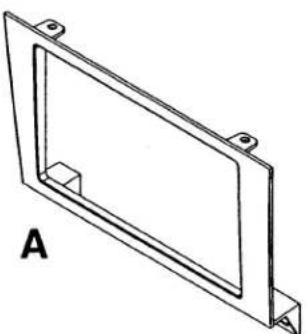
A) Double Din Radio Housing • B) Double DIN Brackets
natural_image
Technical line drawing of a rectangular frame with mounting holes and a small square cutout, labeled 'A' (no text or symbols on the diagram itself)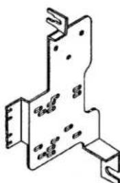
natural_image
Isometric line drawing of a mechanical bracket or mounting plate (no text or symbols)B

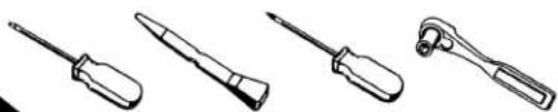
TOOLS REQUIRED:
Small Flat Blade Screwdriver/ Panel Removal Tool
• Phillips Screwdriver • Socket Set
natural_image
Line drawings of four different screwdriver tools (no text or symbols)TABLE OF CONTENTS
Dash Disassembly
- Lexus GS Series 1993-1997....1
Kit Assembly
- Double DIN Radio Provision ....2
- Stacked ISO Mount Units Provision 2
Final Assembly 3
*Note:
Refer also to the instructions included with the aftermarket radio.
LEXUS GS SERIES 1993-1997
1 Disconnect the negative battery terminal to prevent an accidental short circuit.
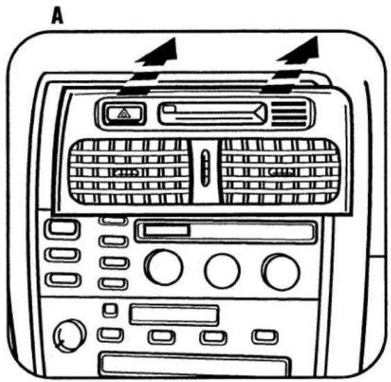
2 Using a panel removal tool gently pry out on the top of the a/c vent assembly (including clock) and remove. (Figure A)
3 Unclip and remove ashtray assembly. Tip: Open ashtray door and pull from inside. (Figure B)
4 Remove (4) screws securing factory radio/climate control assembly. Unplug and remove the assembly. (Figure C)
5 Remove (4) screws securing factory climate controls to the assembly. Remove the climate controls and retain them and the screws for re-installation during kit assembly (Figure D)
Continue to kit assembly.
text_image
A
natural_image
Illustration of a hand pressing down on a mechanical component with a downward arrow (no text or symbols)
natural_image
Technical line drawing of a mechanical device with mounting holes and directional arrows indicating motion (no text or symbols)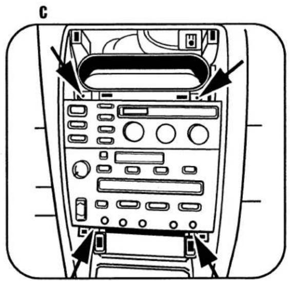
text_image
CLEXUS GS SERIES 1993-1997
DOUBLE DIN RADIO
STACKED ISO MOUNT UNITS PROVISION
Note: Refer also to the instructions included with the aftermarket radio.
1 Snap the Double DIN Brackets onto the Double DIN Radio Housing. (Figure A)
2 Slide the factory climate controls into the Bracket/Radio Housing assembly aligning the top of the assembly with alignment pins in the bottom of the climate controls and secure using the factory hardware. (Figure B)
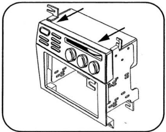
3 Slide the Double DIN or stacked ISO mount units into the bracket/radio housing assembly and secure the Double DIN or stacked ISO mount units to the assembly using the screws supplied with the Double DIN or stacked ISO mount units. (Figure C)
Continue to final assembly.
A

natural_image
Technical line drawing of a mechanical bracket assembly with mounting holes and internal components (no text or symbols)B
natural_image
Technical line drawing of a microwave oven unit with mounting brackets and ventilation slots (no text or symbols)C

natural_image
Technical line drawing of a device housing with mounting brackets and control panel (no text or symbols)FINAL ASSEMBLY
text_image
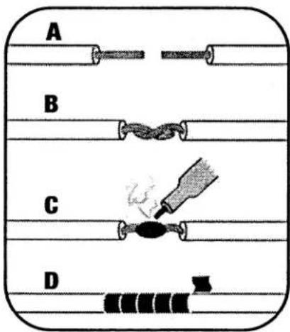
A B C D(A) Strip wire ends back 1/2"
B) Twist ends together
C) Solder
D) Tape
1 Locate the factory wiring harness in the dash. Metra recommends using the proper mating adapter and making connections as shown. (Isolate and individually tape off the ends of any unused wires to prevent electrical short circuit.)
2 Re-connect the negative battery terminal and test the unit for proper operation.
3 Reassemble radio and dash assemblies in reverse order of disassembly.
FINAL WIRING CONNECTIONS
Make wiring connections using the EIA color code chart shown below and the instructions included with the head unit. Metra recommends making connections as shown below; Strip, Splice, Solder, Tape. Isolate and individually tape off ends of any unused wires to prevent electrical short circuit.
METRA / EIA WIRING CODE
| 12V Ignition / Acc. .... . Red | Right Front (+) .... Gray |
| 12V Batt / Memory. .... Yellow | Right Front (-). Gray/ Black |
| Ground. .... Black* | Left Front (+) .... White |
| Power Antenna. .... Blue | Left Front (-). White / Black |
| Amp Turn-On.... Blue / White | Right Rear (+) .... Violet |
| Amp Ground.... Black / White | Right Rear (-). Violet / Black |
| Illumination.... Orange | Left Rear (+) .... Green |
| Dimmer.... Orange / White | Left Rear (-). Green / Black |
*NOTE: When a Black wire is not present, ground radio to vehicle chassis.
All colors may not be present on all leads due to manufacturer's specifications.
NOTES
NOTES
95-8154 INSTRUCTIONS