99-7868 - Car accessory Metra - Free user manual and instructions
Find the device manual for free 99-7868 Metra in PDF.

| Type de produit | Dashboard Installation Kit |
| Marque | Metra |
| Modèle | 99-7868 |
| Matériau | ABS Plastique |
| Couleur | Noir |
| Dimensions (L x H x P) | 7 x 2.75 x 1.5 in (178 x 70 x 38 mm) |
| Poids | 0.5 lb (230 g) |
| Alimentation | N/A (aucune alimentation requise) |
| Radio Size Compatible | DIN unique (2" haut) |
| Véhicules compatibles | Sélection de véhicules GM (spécifier via Metra) |
| Contenu de l'emballage | Kit de montage, support de radio, vis, instructions |
| Fonction principale | Installation d'une radio aftermarket dans un tableau de bord d'origine |
| Installation | Nécessite outils à main de base (tournevis, clé à douille) |
| Difficulté d'installation | Modérée |
| Entretien et nettoyage | Essuyer avec un chiffon doux et sec |
| Sécurité | Bords non coupants; suivre les instructions pour éviter les dommages |
| Pièces détachées | Disponibles via Metra (supports, vis) |
| Réparabilité | Remplacement des composants individuellement possible |
| Garantie | Garantie limitée de 1 an |
| Informations générales | Conçu pour s'adapter parfaitement sans modification du tableau de bord |
Frequently Asked Questions - 99-7868 Metra
User questions about 99-7868 Metra
0 question about this device. Answer the ones you know or ask your own.
Ask a new question about this device
Download the instructions for your Car accessory in PDF format for free! Find your manual 99-7868 - Metra and take your electronic device back in hand. On this page are published all the documents necessary for the use of your device. 99-7868 by Metra.
USER MANUAL 99-7868 Metra
INSTALLATION INSTRUCTIONS FOR PART 99-7868
APPLICATIONS
Acura CL 2001-03
Acura TL 1999-03
99-7868
KIT FEATURES
• DIN Head Unit Provisions with Pocket
• ISO DIN Head Unit Provisions with Pocket
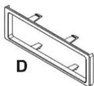
KIT COMPONENTS

natural_image
Front view of a vintage passenger seat counter with control panel and buttons (no visible text or symbols)natural_image
Technical line drawing of a mechanical housing or enclosure with mounting brackets and structural supports (no text or symbols)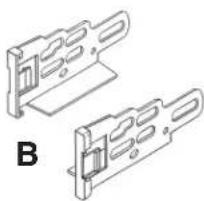
natural_image
Technical line drawing of two mechanical bracket components labeled B (no text or symbols on the brackets)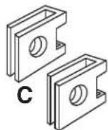

WIRING AND ANTENNA CONNECTIONS (Sold Separately) Harness:
- 70-1721 - Honda/Acura harness 1998-up Antenna Adapter:
- Not required
TOOLS REQUIRED:
Flat Blade Screwdriver
• Phillips Screwdriver


1-800-221-0932

www.metraonline.com
© COPYRIGHT 2004-2009 METRA ELECTRONICS CORPORATION
99-7868
Dash Disassembly 1-2
Kit Assembly
- DIN Head Unit Provision 3
- ISO DIN Head Unit Provision 4
Final Assembly 5

text_image
INSTALLER INSTITUTEKNOWLEDGE IS POWER
Enhance your installation and fabrication skills by enrolling in the most recognized and respected mobile electronics school in our industry. Log onto www.installerinstitute.com or call 800-354-6782 for more information and take steps toward a better tomorrow.
99-7868
ACURA CL / TL
1 Disconnect the negative battery terminal to prevent an accidental short circuit.
2 Unclip and remove wood trim from both sides of center console. (Figure A)
3 Open armrest and remove (2) phillips screws inside and (2) phillips screws at front edge of rear console and pull rearward. (Figure B)
4 Open fuse access and remove (1) phillips screw, then unclip and remove panel below steering column. (Figure C)

text_image
A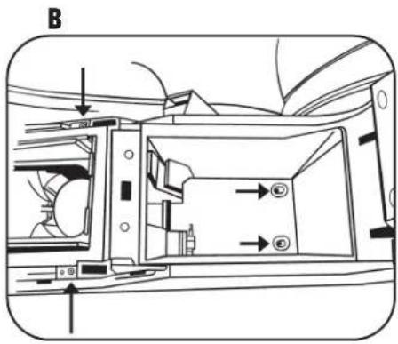
text_image
B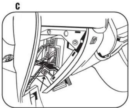
natural_image
Technical line drawing of a mechanical assembly with internal components (no text or symbols)99-7868
ACURA CL / TL
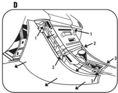
5 Remove (3) phillips screws per center console side panel and remove panels (on driver's and passenger side). (Figure D)
6 Unclip and remove seat heater switch trim panel to access and remove (2) phillips screws (Figure E)
7 Unclip bottom of A/C control trim panel and pull away (no need to completely remove). (Figure F)
8 Remove (3) phillips screws and (1) push pin per side of radio to remove radio. (Figure G)
9 Remove (2) phillips screws from storage pocket assembly above radio to separate. (The storage pocket assembly will have to be attached to the radio housing).
text_image
D 1 2 3 1 2 3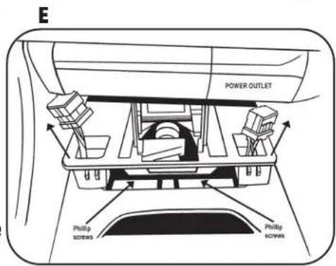
text_image
E POWER OUTLET Philip screws Philip screws
text_image
F
natural_image
Mechanical assembly diagram showing internal components and directional arrows (no text or labels)99-7868
DIN HEAD UNIT PROVISIONS
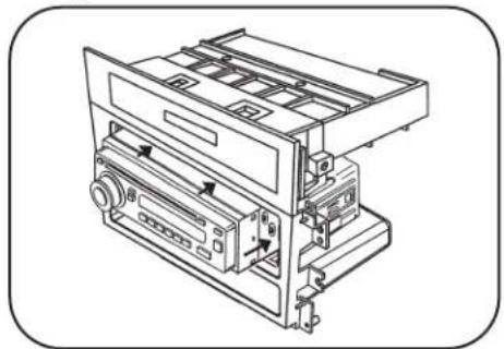
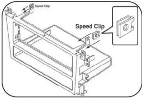
1 Position speed clips provided with the kit onto the top (2) legs on the radio housing. (Figure A)
2 Align holes in top of radio housing with the guide pins on the bottom of the storage pocket assembly and secure the pocket assembly to the legs holding the speed clips with the (2) screws provided. (Figure B)
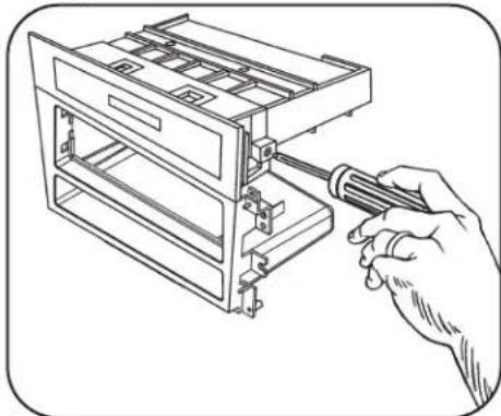
3 Slide the DIN cage into the Radio Housing and secure by bending the metal locking tabs down. (Figure C)
4 Slide the aftermarket head unit into the cage and secure. Snap the trim plate into the housing. (Figure D)
D
natural_image
Technical line drawing of a mechanical device with no visible text or symbolsA
text_image
Speed Clip Speed ClipB
natural_image
Line drawing of a hand using a screwdriver to adjust or install a multi-tiered storage unit (no text or symbols present)C

text_image
Diagram showing a hand using a screwdriver to adjust or install a device with visible text 'SvZn1.5x60' on the screen.99-7868
ISO DIN HEAD UNIT PROVISIONS
1 Position speed clips provided with the kit onto the top (2) legs on the radio housing. (Figure A)
2 Align holes in top of radio housing with the guide pins on the bottom of the storage pocket assembly and secure the pocket assembly to the legs holding the speed clips with the (2) screws provided. (Figure B)
3 Mount the ISO brackets to the head unit with the screws supplies with the unit. (Figure C)
4 Slide the head unit into the radio opening until the side clips engage. Snap the trim plate into the housing. (Figure D)
D

text_image
Side ClipA

text_image
Speed Clip Speed ClipB

natural_image
Line drawing of a hand using a screwdriver to adjust or install a multi-tiered storage unit (no text or symbols present)C

natural_image
Line drawing of a hand using a screwdriver to adjust or install a CD or DVD drive (no text or symbols present)99-7868

text_image
A B C D1 Locate the factory wiring harness in the dash. Metra recommends using the proper mating adapter and making the connections as shown. (Isolate and individually tape off the ends of any unused wires to prevent electrical short circuit)
2 Re-connect the negative battery terminal and test the unit for proper operation.
3 Reassemble radio and dash assemblies in reverse order of disassembly.
INST997868