
95-7350B - Car Radio Metra - Free user manual and instructions
Find the device manual for free 95-7350B Metra in PDF.

| Product Type | Car Radio Installation Kit |
| Brand | Metra |
| Model | 95-7350B |
| Compatible Vehicles | Mazda 5 (2012 and up) |
| Radio Provision | Double DIN |
| Finish | Matte Black, scratch-resistant |
| Included Components | Radio housing, radio brackets |
| Required Wiring Harness (sold separately) | 70-7903 (Mazda harness) |
| Required Antenna Adapter (sold separately) | 40-HD10 (Honda antenna adapter) |
| Tools Required | Panel removal tool, Phillips screwdriver, socket wrench |
| Installation Note | Disconnect negative battery terminal before starting |
| Certification Recommendation | MECP certified technicians recommended |
| Manual Pages | 16 |
| Manual Format | PDF (English, Spanish) |
| Additional Features | Step-by-step dash disassembly and assembly instructions |
Frequently Asked Questions - 95-7350B Metra
User questions about 95-7350B Metra
0 question about this device. Answer the ones you know or ask your own.
Ask a new question about this device
Download the instructions for your Car Radio in PDF format for free! Find your manual 95-7350B - Metra and take your electronic device back in hand. On this page are published all the documents necessary for the use of your device. 95-7350B by Metra.
USER MANUAL 95-7350B Metra
INSTALLATION INSTRUCTIONS FOR PART 95-7521B
APPLICATIONS
Mazda 5 2012-up
95-7521B
KIT FEATURES
- Double DIN head unit provision
- Painted scratch-resistant Matte Black
KIT COMPONENTS
natural_image
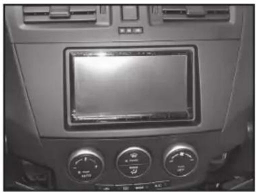
Interior view of a car dashboard with air conditioners and a digital display (no visible text or symbols)A) Radio Housing • B) Radio Brackets
A

natural_image
Technical line drawing of a rectangular device with mounting brackets and a central panel (no text or symbols)B
natural_image
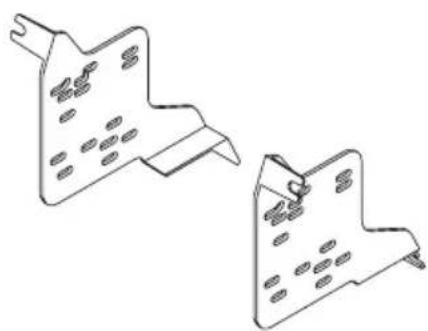
Two isometric technical drawings of metal bracket components with holes (no text or symbols)WIRING & ANTENNA CONNECTIONS (Sold Separately)
WiringHarness:
• 70-7903 - Mazda harness
Antenna Adapter:
• 40-HD10 - Honda antenna adapter
TOOLS REQUIRED
Panel Removal Tool • Phillips Screwdriver • Socket Wrench

natural_image
Three types of tools: a pointed tool, a screwdriver, and a adjustable wrench (no text or symbols present)Metra recommends disconnecting the negative battery terminal before beginning any installation. All accessories, switches, and especially air bag indicator lights must be plugged in before reconnecting the battery or cycling the ignition.
*NOTE: Refer also to the instructions included with the aftermarket radio.

KNOWLEDGE IS POWER
Enhance your installation and fabrication skills by enrolling in the most recognized and respected mobile electronics school in our industry. Log onto www.installerinstitute.com or call 800-354-6782 for more information and take steps toward a better tomorrow.

Metra recommends MECP certified technicians
Dash Disassembly
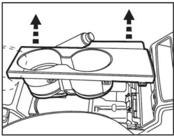
- Unclip and remove the cup holder panel in the center console. (Figure A)
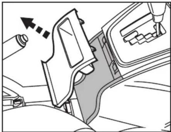
- Unclip and remove the small pocket panel on the back of the center console behind shifter. (Figure B)
- Remove (2) 8mm bolts under cup holder panel holding the back half of the center console to the front half. (Figure C)
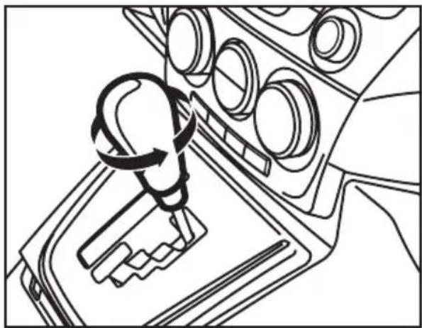
- Unscrew and remove the shift knob. (Figure D)
Continued on next page
natural_image
Technical line drawing of a vehicle engine cylinder assembly with no visible text or symbols(Figure A)
natural_image
Technical line drawing of a car seatbelt mechanism with no visible text or symbols(Figure B)

natural_image
Technical line drawing of a mechanical assembly with mounting holes and connectors (no text or symbols)(Figure C)
natural_image
Line drawing of a car gear shift lever mechanism (no text or symbols)(Figure D)
Dash Disassembly
- Unclip and remove the shifter trim panel. (Figure D)
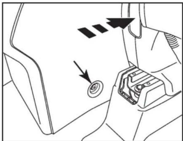
- Slide both seats forward and remove (2) Phillips screws on each side of the center console under the screw covers. (Figure E)
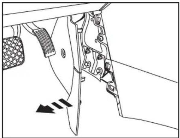
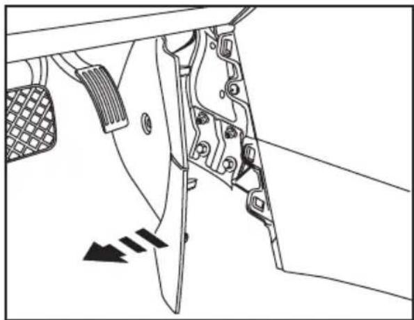
- Unclip and pull back the panels at the lower front sides of the center console. (Figure F)
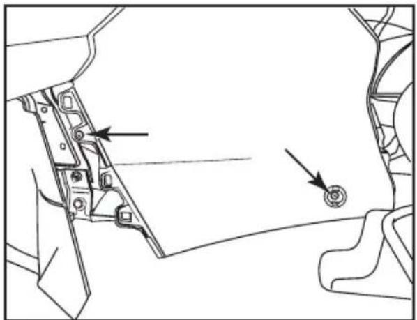
- Remove (2) Phillips screws from both sides (total of 4) of the front lower half of the center console. (Figure G) Continued on next page

natural_image
Diagram of a car seatbelt mechanism showing the switch and gear shift (no text or symbols)(Figure D)

natural_image
Diagram of a car seatbelt mechanism with directional arrows indicating movement or force (no text or symbols present)(Figure E)
natural_image
Technical line drawing of a mechanical component with no visible text or symbols(Figure F)
natural_image
Technical line drawing of a mechanical component with two arrows pointing to specific parts (no text or symbols present)(Figure G)
Dash Disassembly
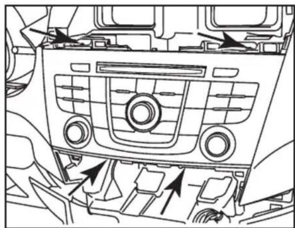
- Unclip and remove the vent panel including the hazard switch above the factory radio. (Figure H)
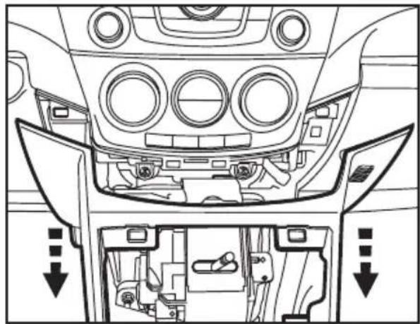
- Unclip the entire center console and slide it towards the rear of the vehicle to gain access to the (2) Phillips screws on the bottom of the a/c control. (Figure I)
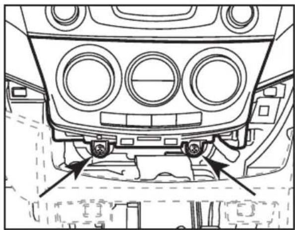
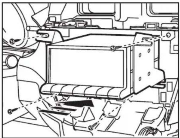
- Remove the (2) Phillips screws from the a/c control then unclip and remove the control. (Figure J)
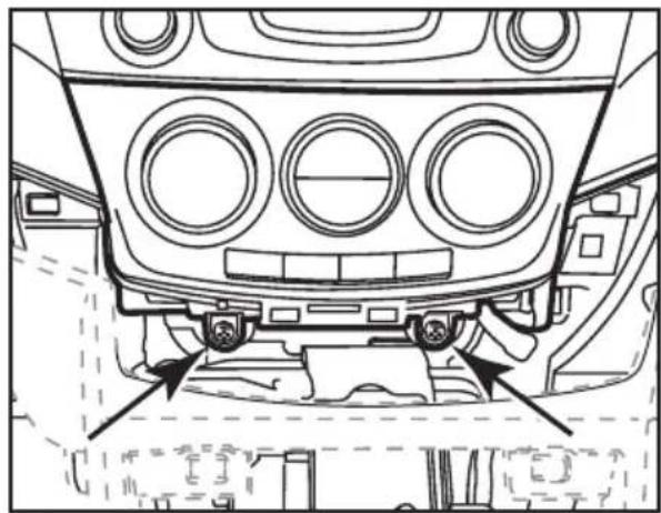
- Remove (3) Phillips screws and (1) 10 mm bolt securing the radio. (Figure K)
Continue to kit assembly

natural_image
Interior view of a car dashboard with air vent and control panel (no text or symbols)(Figure H)

natural_image
Top-down line drawing of a car's front dashboard and rear seats, showing structural components without any text or symbols.(Figure I)
natural_image
Technical line drawing of a vehicle's front dashboard and rear seats, showing structural components without any text or symbols.(Figure J)
natural_image
Line drawing of a car dashboard with air vent and directional arrows indicating engine or airflow (no text or symbols)(Figure K)
Double DIN head unit provisions
- Mount the radio to the radio brackets with the screws supplied with the unit. (Figure A)
- Locate the factory wiring harness in the dash. Metra recommends using the proper mating adapter from Metra or AXXESS. Test the unit for proper operation.
- Mount the radio/bracket assembly into the dash. (Figure B)
- Install the radio trim panel over the radio/bracket assembly and reassemble dash in reverse order of disassembly.

natural_image
Technical line drawing of an electronic device casing with mounting screws and internal components (no text or symbols)(Figure A)
natural_image
Technical line drawing of a vehicle chassis with internal components and mounting brackets (no text or symbols)(Figure B)
Notes
APLICACIONES
Mazda 5 2012 y mas
95-7521B
CARACTERÍSTICAS DEL KIT
natural_image
Interior view of a car dashboard with air conditioners and a digital display (no visible text or symbols)natural_image
Technical line drawing of a rectangular device with mounting brackets and a central recessed opening (no text or symbols)B

natural_image
Two technical line drawings of a mechanical bracket or bracket component (no text or symbols)natural_image
Line drawings of three different tools: a pointed tool, a screwdriver, and a adjustable wrench (no text or symbols present)Indice
Enhance your installation and fabrication skills by enrolling in the most recognized and respected mobile electronics school in our industry. Log onto www.installerinstitute.com or call 800-354-6782 for more information and take steps toward a better tomorrow.

Metra recommends MECP certified technicians
natural_image
Technical diagram of a vehicle engine compartment showing internal components and airflow direction (no text or labels)(Figure A)

natural_image
Technical line drawing of a car seatbelt assembly with no visible text or symbols(Figure B)

natural_image
Technical line drawing of a mechanical component with two arrows pointing to specific parts (no text or symbols present)(Figure C)

natural_image
Line drawing of a car gear shift lever mechanism (no text or symbols)(Figure D)
natural_image
Diagram of a car gear shift lever with an arrow indicating direction (no text or symbols present)(Figure D)
(Figure E)
natural_image
Technical line drawing of a mechanical component with no visible text or symbols(Figure F)

natural_image
Technical line drawing of a mechanical component with two arrows pointing to features (no text or symbols)(Figure G)
natural_image
Interior view of a car dashboard with air vent and control panel (no text or symbols)(Figure H)
natural_image
Top-down line drawing of a car's front dashboard and rear seats, showing structural components without any text or symbols.(Figure I)
natural_image
Technical line drawing of a car front bumper with circular vented seating and mounting fixtures (no text or symbols)(Figure J)

natural_image
Line drawing of a car interior showing dashboard, air vent, and engine compartment with directional arrows indicating flow or movement (no text or symbols)(Figure K)
natural_image
Technical line drawing of an electronic device casing with mounting screws and internal components (no text or symbols)(Figure A)

natural_image
Technical line drawing of a vehicle chassis with internal components and mounting brackets (no text or symbols)(Figure B)
Notas
- INSTALLATION INSTRUCTIONS FOR PART 95-7521B
- APPLICATIONS
- Mazda 5 2012-up
- 95-7521B
- KIT FEATURES
- KIT COMPONENTS
- WIRING & ANTENNA CONNECTIONS (Sold Separately)
- TOOLS REQUIRED
- KNOWLEDGE IS POWER
- Dash Disassembly
- Double DIN head unit provisions
- Notes
- APLICACIONES
- Mazda 5 2012 y mas
- CARACTERÍSTICAS DEL KIT
- Indice
- Notas
Brand : Metra
Model : 95-7350B
Category : Car Radio