PDWM8225 - Speaker Pyle - Free user manual and instructions
Find the device manual for free PDWM8225 Pyle in PDF.

| Product Type | Portable Bluetooth Speaker |
| Brand | Pyle |
| Model | PDWM8225 |
| Dimensions (L x W x H) | 8.0 x 4.5 x 4.0 inches |
| Weight | 2.1 lbs |
| Power Supply | Built-in rechargeable battery (DC 5V via USB) |
| Battery Life | Up to 8 hours at 50% volume |
| Charging Time | Approximately 3-4 hours |
| Bluetooth Version | 5.0 |
| Wireless Range | Up to 33 feet (10 meters) |
| Audio Output Power | 20W (RMS) |
| Speaker Driver | 3-inch full range driver |
| Frequency Response | 80Hz - 18kHz |
| Signal-to-Noise Ratio | ≥ 85 dB |
| Inputs | Bluetooth, AUX (3.5mm), USB port for charging |
| Controls | Power, Volume +/-, Play/Pause, Next/Previous Track, Pairing button |
| Water Resistance | IPX4 (splash-proof) |
| Microphone | Built-in for hands-free calling |
| Compatibility | Smartphones, tablets, laptops with Bluetooth or AUX |
| Accessories Included | USB charging cable, AUX cable, user manual |
| Cleaning Instructions | Wipe with a soft, dry cloth. Do not use abrasive cleaners or immerse in water. |
| Safety Warnings | Do not expose to extreme temperatures or moisture. Keep away from children. |
| Spare Parts Availability | Contact Pyle customer service for replacement parts. |
| Repairability | Non-user serviceable. Refer to qualified service personnel for repairs. |
| General Information | Designed for indoor/outdoor use with rich sound quality and portable design. |
Frequently Asked Questions - PDWM8225 Pyle
User questions about PDWM8225 Pyle
0 question about this device. Answer the ones you know or ask your own.
Ask a new question about this device
Download the instructions for your Speaker in PDF format for free! Find your manual PDWM8225 - Pyle and take your electronic device back in hand. On this page are published all the documents necessary for the use of your device. PDWM8225 by Pyle.
USER MANUAL PDWM8225 Pyle
Need service or repair?
Want to leave a comment?
PyleUSA.com/ContactUs

PYLEPRO
PyleUSA.com
natural_image
Electrical setup with multiple audio amplifiers and connected devices (no visible text or labels)PDWM8225

natural_image
Front view of a black rack-mounted electronic device with multiple vertical channels and indicator lights (no visible text or labels)
natural_image
Diagram of a multi-chamber electronic device with multiple connected modules and connectors (no text or labels)PDWM8250PDWM8275
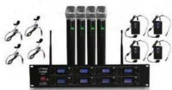
- Receiver X1
- Wireless hand-held or body-pack microphone X8
- Audio Cable X1
- AC power adapter of special receiver X1
- Battery 1.5V X16
6.User guide X1
This professional wireless set provides a high quality microphone with UHF radio system for freedom of movement without loss of audio quality. Please read this manual before using this equipment in order to avoid damage through incorrect operation and to get the best performance from your purchase. This series of professional wireless microphone system used a super steady PLL - synthesized control technic and matches the high efficient, low consumption discharging technique and super sensitive discharging receiving technique, also apply an independent developed mobile frequency compression, expander circuit, image frequency limiting circuit, a multiple checked silent and noisy circuit, antenna diversity receiving circuit, switch impact noise defeat circuit, resist reverberation circuit and changed output controlled slowly system and finished on its item named pattern line. Eery system is available to an excellent electric function by Q.C. strictly.
FOREWORD
Your new series of wireless system is designed to give you the best of both sound reinforcement worlds: the freedom of wireless system, and excellent quality. This manual covers each of the series system: The VocalArtist-UHF, The Presenter-UHF, The Headset-UHF, and The Guilarist-UHF.
SYSTEM FEATURES
- Adopt the PLL-Synthesized control technic, Multi-UHF channels.
- The UHF frequency range is 523-597.8 MHz, avoiding the frequency interruption.
- LCD information display.
- Double noise squelch operation circuit and system will be higher, efficient and much more steady.
- Use the dynamic type and Uni-directional cartridge, clear to show the sound.
- High efficient and low consumption design.
- Use the high extension antennas, the operating distance will reach 50m.
SYSTEM TYPE
The Vocal Artist-UHF is a hand-held system designed for singers who desire the high quality of microphones and the freedom of wireless performance.
The Presenter-UHF is a body-pack system designed for public speakers who prefer an inconspicuous, hands-free lavalier microphone.
The Headset-UHF is a body-pack system designed for users in physically active applications, who desire the freedom of hand-free microphone.
The Guitarist-UHF is a body-pack system designed for use with electric guilars, basses, and other electric instruments.
FOUR CHANNEL RECEIVER FEATURES
text_image
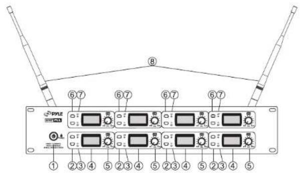
PYLE 2001/2013 ① ② ③ ④ ⑤ ② ③ ④ ⑤ ② ③ ④ ⑤ ② ③ ④ ⑤Front Panel
text_image
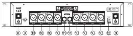
UHF CCE 8 9 10 10 10 10 11 11 10 10 10 10 12 8Rear Panel
- Power Button: Power ON/OFF the receiver.
- Down Function Button: Sets channel data.
- "RF" Signal Indicator: It glows when the Receiver receive RF signal from Transmitter.
- LCD Information Display: Show the receiver frequency channel ect.
- Volume Knob: Adjust the volume output of receiver.
- Up Function Button: Sets channel data.
- AF Audio Level Indicator: Indicate the wireless system audio signal level.
- Antenna.
- Power switch of CH5-8: When switch to "ON" position, it means CH5 to CH8 is on, all channels from 1 to 8 is on for working. When switch to "OFF" position, it means CH5 to CH8 is off, only CH1 to CH4 is ON for working.
- XLR Balanced Output Jack: Connect the audio cable from this jack to the input port of amplifier, mixer.
- 1/4" Audio Output Jack: Connect the audio cable from this jack to the input port of amplifier, mixer. (CH1-4 or CH5-8)
- Power Jack: Connect the AC/DC adapter to receiver.
MICROPHONE-TRANSMITTER FEATURES
text_image
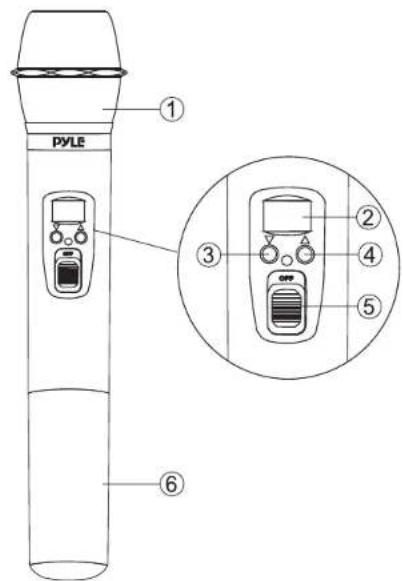
PYLE ① ③ ② ④ ⑤ ⑥- Grille: Protects the cartridge and help reducing the breath sounds and wind noise.
- LCD Information Display: Show the transmitter frequency channel ect.
- Down Function Button: Sets channel data.
- Up Function Button: Sets channel data.
- Power and Audio Mute Switch.
- Battery Cover: Open it to install the battery.
BODY-PACK TRANSMITTER FEATURES

text_image
PYLE DISPLAY SELL-PACIFIC TRANSMITTER ④ ① ⑤ ② ⑥ ③ AA SIZE AA SIZE ⑦ ⑧ ⑨ ⑩- Power and Audio Mute Switch.
- Antenna: Transmit the RF signal of transmitter.
- Belt Clip: Attach the transmitter to the belt.
- Audio Input Jack: Suitable for lavalier system/headset system.
- Low Battery Indicator: Red light glows when it is lack of power and should renew the battery.
- LCD Information Display: Show the transmitter frequency channelect.
- Gain Adjusting Volume: Adjust the transmitter audio input gain.
- State Setting Switch: Set the using state of lavalier system (L) / headset system (H) / guitar system (G).
- Up Function Button: Sets channel data.
- Down Function Button: Sets channel data.
TRANSMITTER BATTERY INSTALLATION
- Battery Installation of Handheld Microphone: Open the battery cover. Insert the supplied batteries into battery jar in polarity and cover the battery.
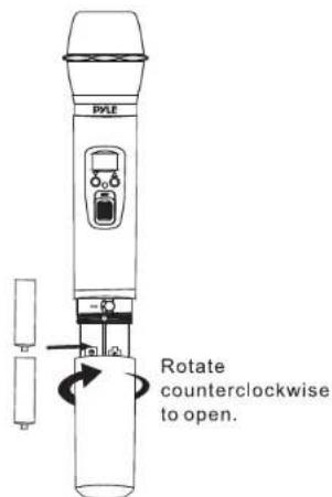
text_image
PALE Rotate counterclockwise to open.- Battery Installation of Bodypack Transmitter: Push open the battery cover. Insert the supplied batteries into battery jar in polarity and close the battery cover.
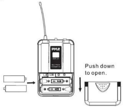
text_image
PYLE Push down to open.BODYPACK TRANSMITTER CONNECTION
- Lavalier Microphone Connection: Connect the connector of supplied lavalier microphone to the connecting jack of transmitter (shown as below) Set the transmitter work state in wireless lavalier system (L).

(a)
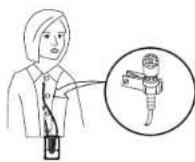
(b)
- Headset Microphone Connection: Connect the connector of supplied headset microphone to the connecting jack of transmitter (shown as below) Set the transmitter work state in wireless headset system (H).

(a)
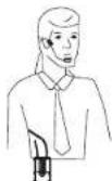
(b)
OPERATING INSTRUCTIONS
- Receiver Operation: Power ON receiver, press twice "UP" button of module 2 and 3 together for 1 second to enter the adjustment, when the LCD displays "UnLOC", it is under "Normal Operation". When the LCD displays "LOC", it is under "Locking Operation".
a. Normal Operation
- Press and hold "UP"JWDOWN button, release the button once the CH number begins to flash
- When it is flashing, continue to press "UP/DOWN" button to increase /decrease the channel orderly, select the desired channel
- The selected channel will be saved automatically without any action for 5 seconds
- Please refer to the following list for showing the adjusting channels.
b. Locking Operation
- Press and hold "UP/DOWN" button, release the button once the CH number begins to flash
- When flashing, continue to press "UP/DOWN" button to increase/decrease the channel orderly, select the desired channel
- Once done with the channel adjustment of any module, the channels of the other seven modules will be changed automatically without any action to select the channels under same group.
- The channels will be save automatically for using without any action for 5 seconds.
- Please refer to the following list for showing group information.
2. Transmitter Operation
Power ON transmitter
- Press and hold "UP/DOWN" button, release the button once the CH number begins to flash
- When it is flashing, continue to press "UP/DOWN" button to increase /decrease channel orderly, select the same channel as chosen on receiver.
-
The selected channel will be saved automatically without any action for 5 seconds.
-
Please pay attention: In using multi-microphones together with better effect (less interference), we suggest to choose 8 frequencies under same group for using.
| Adjustable Freq.from Module 1 to4 | Adjustable Freq.from Module5 to8 | |||||||
| Group "0" | CH:01 | CH:02 | CH:03 | CH:04 | CH:05 | CH:06 | CH:07 | CH:08 |
| 523.200 | 525.525 | 539.400 | 545.075 | 573.225 | 577.975 | 585.375 | 595.375 | |
| Group"1" | CH:11 | CH:12 | CH:13 | CH:14 | CH:15 | CH:16 | CH:17 | CH:18 |
| 523.500 | 525.925 | 539.700 | 545.375 | 573.525 | 578.275 | 585.575 | 595.575 | |
| Group "2" | CH:21 | CH:22 | CH:23 | CH:24 | CH:25 | CH:26 | CH:27 | CH:28 |
| 523.800 | 527.225 | 540.000 | 545.575 | 573.825 | 578.575 | 585.975 | 595.975 | |
| Group "3" | CH:31 | CH:32 | CH:33 | CH:34 | CH:35 | CH:36 | CH:37 | CH:38 |
| 524.100 | 527.525 | 540.300 | 545.975 | 574.125 | 578.875 | 587.275 | 595.275 | |
| Group "4" | CH:41 | CH:42 | CH:43 | CH:44 | CH:45 | CH:46 | CH:47 | CH:48 |
| 524.400 | 527.825 | 540.500 | 545.275 | 574.425 | 579.175 | 587.575 | 595.575 | |
| Group "5" | CH:51 | CH:52 | CH:53 | CH:54 | CH:55 | CH:56 | CH:57 | CH:58 |
| 524.700 | 528.125 | 540.900 | 545.575 | 574.725 | 579.475 | 587.875 | 595.875 | |
| Group "6" | CH:61 | CH:62 | CH:63 | CH:64 | CH:65 | CH:66 | CH:67 | CH:68 |
| 525.000 | 528.425 | 541.200 | 545.875 | 575.025 | 579.775 | 588.175 | 597.175 | |
| Group "7" | CH:71 | CH:72 | CH:73 | CH:74 | CH:75 | CH:76 | CH:77 | CH:78 |
| 525.300 | 528.725 | 541.500 | 547.175 | 575.325 | 580.075 | 588.475 | 597.475 | |
| Group "8" | CH:81 | CH:82 | CH:83 | CH:84 | CH:85 | CH:86 | CH:87 | CH:88 |
| 525.500 | 529.025 | 541.800 | 547.475 | 575.525 | 580.375 | 588.775 | 597.775 | |
SYSTEM CONNECTION
- Receiver Power Connection: Connect the DC connector of supplied AC/DC adapter Into the DC power input of receiver. Plug the AC Input connector into an AC120/60Hz or AC220V/50Hz outlet. (Shown as below)

natural_image
Front view of a rack-mounted electronic device with multiple power connectors and indicator lights (no visible text or labels)- Antenna: Keep the position of antenna at a 45 angle from vertical. (Shown as below)
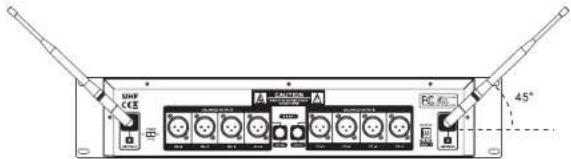
text_image
UHF CEE 45°- Audio Connection: Connect the corresponding output of receiver by supplied 1/4w phone jack audio cable or your XLR cable to the Input of power amplifier, mixer.

text_image
Diagram showing audio equipment connections between two speakers and a central computer interface with multiple ports and signal lines.TROUBLESHOOTING
| PROBLEM INDICATOR STATUS SOLUTION | ||
| No Sound | Red transmitter indicator is not flashing | Slide transmitter POWER ON/OFF switch to ON position. Make sure battery is inserted properly, observing battery (+/-). If the battery is inserted properly, replace with fresh battery. |
| No Sound | Red transmitter indicator is flashing | Slide transmitter MUTE/ON switch to ON position |
| No Sound | Red receiver POWER light off | Make sure AC adapter is securely plugged into electrical outlet and into DC input connector. Make sure AC electrical outlet works and supplies proper voltage |
| No Sound | Receiver signal indicators A/B lights glowing | Trun up receiver volume control. Confirm that the output connections from the receiver to the external equipment are secure |
| No Sound | Receiver signal indicators A/B lights off. Transmitter and receiver POWER lights glowing | Confirm transmitter and receiver~ frequency match. Move transmitter closer to receiver. |
| Sound level differs from the level of a cabled Instrument. | Receiver signal indicators A/B lights glowing | Adjust transmitter gain level to compensate. Adjust receiver volume as necessary |
| Sound level differs from the level of different guitars | Receiver signal indicators A/E lights glowing | Readjust transmittergain level to compensate differences in guitar outputs |
| Distortion level increases gradually | Receiver signal indicators A/B lights and transmitter LOW BATTERY light glowing | Replace transmitter battery |
| Bursts of noise or other audible radio signals present | Signal indicators A/B lights ON | Identify potential sources of interference (other RF sources) and turn OFF, remove or use a wireless system operating on a different frequency |
| Momentary loss of sound as transmitter is moved around performing area. | Receiver signal indicator A/B lights OFF when sound is lost | Reposition receiver and perform walk-through again. If audio dropouts persist, mark "dead" spot-and avoid them during performance. |
SYSTEM SPECIFICATIONS
• RF Carrier Frequency Range:
Approximately 523 to 597.8 MHZ (Available frequencies depend on applicable regulations in country where system is used).
- Operating Range: 50m (approximately 164ft) under typical conditions
• Audio Frequency Response: 100 to 18,000Hz, ±3dB - THD: <1%
- Mobile state Range: > 100dB
Operating Temperature Range
-20.2°F to 165.2°F (-29°C to 74°C)
NOTE: Battery characteristics may limit this range.
OPTIONAL ACCESSORIES
1/4" to 1/4" Cable (The Guitarist -UHF only)
1/4" to Miniature Connector
1.8 Meter (6ft.) Receiver-Mixer Cable
RECEIVER SPECIFICATION
| Power Requirements | 120V or 230VAC adaptor with 2.1mm female plug |
| Power Requirements | 13 -15 V DC nominal, 500mA+ |
| Signal/Noise Ratio | MORE THAN 85dB |
| Border Upon ChannelRejection | MORETHAN 70dB |
| Image & Spurious Rejection | MORETHAN 70dB |
| Audio OutputLevel | ( ).±300mV |
| Receiving Sensitivity | -105dBm |
| Dimensions | 482MM X 223MM X 97MM |
HAND-HELD TRANSMITTER SPECIFICATIONS
| Power Requirements 1.5VAA battery X | 2 |
| Nominal Current Drain LESS THAN 100mA | |
| Modulation Type | FM |
| RF Output MORE THAN | 10dBm |
| Max Deviation | ±70KHz |
| Spurious Emission MORE THAN | 55dB |
| Dimensions | 257MM X 51.5MM X 51.5MM |
BODY-PACK TRANSMITTER SPECIFICATIONS
| Power Requirements | 1.5VAA battery X2 |
| Nominal Current Drain LESS THAN 100mA | |
| Modulation Type | FM |
| RF Output MORE THAN | 10dBm |
| Max Deviation | ±70KHz |
| Spurious Emission MORE THAN | 55dB |
| Dimensions | 105MM X 65MM X 30MM |