EB-L1065UNL - Video projector EPSON - Free user manual and instructions
Find the device manual for free EB-L1065UNL EPSON in PDF.

User questions about EB-L1065UNL EPSON
0 question about this device. Answer the ones you know or ask your own.
Ask a new question about this device
Download the instructions for your Video projector in PDF format for free! Find your manual EB-L1065UNL - EPSON and take your electronic device back in hand. On this page are published all the documents necessary for the use of your device. EB-L1065UNL by EPSON.
USER MANUAL EB-L1065UNL EPSON
Notations Used in This Guide
•Safety indications
The documentation and the projector use graphical symbols to show how to use the projector safely.
The indications and their meaning are as follows. Make sure you understand them properly before reading the guide.
| Warning | This symbol indicates information that, if ignored, could possibly result in personal injury or even death due to incorrect handling. |
| Caution | This symbol indicates information that, if ignored, could possibly result in personal injury or physical damage due to incorrect handling. |
•General information indications
| Attention | Indicates procedures which may result in damage or injury if sufficient care is not taken. |
| Indicates additional information and points which may be useful to know regarding a topic. | |
| Indicates a page where detailed information regarding a topic can be found. | |
| [Name] Indicates the name of the buttons on the remote control or the control panel.Example: [Esc] button | |
| Menu Name Indicates Configuration menu items.Example:Select Brightness from Image.Image - Brightness | |
Make sure you read the following before you use the projector.
Safety Instructions
Warning and Cautions on Installation
An optional ceiling mount is required when suspending the projector from a ceiling.
"Optional Accessories" p.233

Warning
- Do not use or install the projector where it may be subject to water or rain, or high humidity, such as outdoors, in a bathroom, or shower room, and so on. Otherwise, it could cause a fire or electric shock.
- Do not install in locations where salt damage could occur, or in locations subject to corrosive gas such as sulphuric gas from hot springs. Otherwise, corrosion could cause the projector to fall. It could also cause the projector to malfunction.
- A special method of installation is required when suspending the projector from a ceiling (ceiling mount). If installation work is not carried out correctly, the projector could fall down. This may result in injury or accidents. Contact your local dealer or the nearest address provided in the Epson Projector Contact List.
Epson Projector Contact List
- Failure to install the ceiling mount and projector may cause the projector to fall. After installing the specific Epson mount that supports your projector, make sure you secure the projector and the mount using wire that is strong enough to hold their weight.
- If you use adhesives on the ceiling mount fixing points to prevent the screws from loosening, or if you use things such as lubricants or oils on the projector, the projector case may crack causing it to fall from its ceiling mount. This could cause an accident or injury to anyone under the ceiling mount.
When installing or adjusting the ceiling mount, do not use adhesives, lubricants, oils, and so on to prevent the screws from loosening.

Warning
- Do not install the projector in locations subject to high humidity or dust, or locations subject to oil or steam, such as kitchen counters, kitchens, or near humidifiers. Otherwise, electric shock or fire could occur. Also, oily particle in the air could cause the projector case to deteriorate causing the projector to fall from the mount if it is suspended from a ceiling.
- Do not cover the projector's air intake vent or air exhaust vent. If either of the vents are covered, the internal temperature could rise and cause a fire.
- Do not place flammable objects in front of the lens. If you set the schedule to turn on the projector automatically, any flammable objects placed in front of the lens could cause a fire.
- Do not tie the power cord and other connection cables together. Otherwise, it could cause a fire.
- Only use the specified power-supply voltage. Otherwise, it could cause a fire or electric shock.

Warning
- Be careful when handling the power cord. Otherwise, it could cause a fire or electric shock. Note the following when handling the power cord.
- Do not plug multiple power cords in a single electric outlet.
- Do not plug in the power cord if there are any foreign substances, such as dust, stuck to it.
- Make sure you insert the power cord all the way in.
- Do not plug in or unplug the power cord with wet hands.
- Do not pull the cord when unplugging the power cord. Make sure you hold it by the plug.
- Do not use a damaged power cord. Otherwise, it could cause a fire or electric shock. Note the following when handling the power cord.
- Do not alter the power cord.
- Do not place any heavy objects on the power cord.
- Do not bend, twist, or pull the power cord forcibly.
- Do not layout the power cord near a heating device.

Caution
Do not place the projector on an unstable surface, such as on an unstable table or tilted surface. When projecting vertically, install the projector appropriately to prevent the projector from falling.
Otherwise it may cause an injury.
Attention
- Do not install the projector in a location that is subject to vibration or shock.
- Do not install the projector near a high-voltage line or object that generates magnetism. Otherwise the projector may not work correctly.
- Do not use or store the projector in a location that is subject to extreme temperatures. Also, avoid sudden temperature changes.
Make sure you maintain the operating or storage temperature ranges. “Projector General Specifications” p.279
- When installing the projector in an environment in which a high-powered laser beam is being used, make sure it is installed so that the laser beam does not hit the surface of the projection lens.
- When using at an altitude that exceeds 1,500 m, set High Altitude Mode to On.
Extended - Operation - High Altitude Mode p.146
- The projector can be installed at any angle. There is no vertical or horizontal limit to how the projector can be installed.
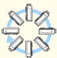
natural_image
Circular arrangement of six identical mechanical components arranged in a ring, no text or symbols present.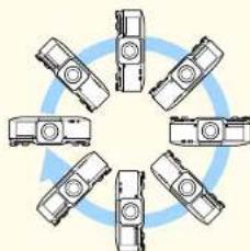
natural_image
Circular diagram with six identical mechanical components arranged in a ring, no text or symbols present.- You may need dedicated installation mounts to tilt and install the projector. Contact a professional and prepare the mount.
- Plan so that the mount does not fall.
Attention
- Make sure you secure the following space around the projector so as not to block the air exhaust vent and the air intake vent.


- When setting up multiple projectors, make sure there is a gap of at least 70 cm between the projectors. Also, make sure that the heat from the air exhaust vent does not go into the air intake vent.

- Secure the following space when placing a partition between projectors.

text_image
30cm 30cmAttention
- Do not stack projectors directly on top of each other.
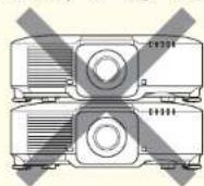
- When using the ceiling mount or the portrait mount, use commercially available M6 screws (up to a depth of 14 mm) to fix the projector's ceiling mount fixing points and the mount at four points.
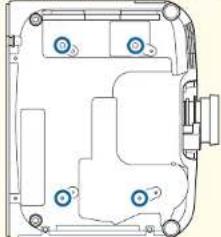
natural_image
Pure technical line drawing of a mechanical assembly without any text, numbers, or symbols
- We recommend setting the focus, zoom, and lens shift at least 20 minutes after you start the projection, because images are not stable right after turning on the projector.
- When adjusting the image height with the vertical lens shift, adjust by moving the image from the bottom to the top. If it is adjusted from the top to the bottom, the image position may move down slightly after adjusting.
Warning and Cautions on Usage

Warning
- Do not cover the projector's air intake vent or air exhaust vent. If either of the vents is covered, the internal temperature could rise and cause a fire.
- Do not look into the lens while projecting. The powerful light emitted could cause damage to eyesight. Take particular care when there are children present. When turning on the projector at a distance using the remote control, make sure there is no one looking into the lens.
- During projection, do not block the light from the projector with the lens cover (removable) or a book and so on.
If the light from the projector is blocked, the area on which the light shines becomes hot which could cause it to melt, burn, or start a fire. Also, the lens may get hot due to the reflected light which could cause the projector to malfunction. To stop projection, use the A/V Mute function, or turn off the projector. - Do not open the projector's case. Never disassemble or remodel the projector. There are high-voltage components inside the projector that could cause fire, electric shock, or an accident.
- If an error occurs, disconnect the power cord from the electrical outlet, and contact your local dealer or the nearest address provided in the Epson Projector Contact List. If you continue using the projector as it is, it could cause an electric shock, fire, or even damage to eyesight.
Epson Projector Contact List

Caution
Do not place objects that may become warped or otherwise affected by heat near the air exhaust vent and do not put your face or hands near the vent while projection is in progress.
Attention
- Only remove the lens unit when necessary. If dust or dirt enter the projector, projection quality deteriorates and it could cause a malfunction.
- Try not to touch the lens section with your hand or fingers. If fingerprints or oils are left on the surface of the lens, projection quality deteriorates.
- If you continue to project while the surface of the lens is dirty, projection quality deteriorates. Make sure you clean the lens. “Cleaning the Lens” p.204
- Store the projector with the lens unit installed. If the projector is stored without the lens unit, dust and dirt may get inside the projector and cause malfunctions or lower the quality of projection.
- When storing, make sure you remove the batteries from the remote control. If the batteries are left in the remote control for an extended period of time, they may leak.

- About the LCD panel
- The LCD panel may contain pixels that are missing or appear bright all the time. This is not a sign of an error.
- When a high-powered laser beams through the surface of the projection lens even when it is not being used, it can cause a malfunction in the LCD panel. Attach the lens cover when storing the projector.
- About the light source
The projector uses a laser as the light source. The laser has the following characteristics.
- Depending on the surroundings, the brightness of the light source may decline. The brightness declines a lot when the temperature gets too high.
- The brightness of the light source declines the longer it is used. You can change the relationship between usage time and decline in brightness in Brightness Settings.
"Relationship between Brightness Level and light source operation time" p.78
- About Light Source Calibration
- When Run Periodically is set to On for Light Source Calibration, every time the usage time reaches 100 hours, calibration starts automatically for the light source when the projector is turned off. However, this does not start automatically when the projector is used continuously for more than 24 hours, or when direct shutdown is used regularly. Set Light Source Calibration in the scheduling function.
"Scheduling Function" p.112
- When performing Light Source Calibration, the difference between the white balance and the brightness level for the light source is corrected.
Reset - Light Source Calibration - Run Periodically p.162
Warning and Cautions on the Laser

Warning
- Laser warning labels are attached inside the projector and on the side of the projector.
Inside

text_image
CAUTION / DANGER CAUTION DANGER: CLASS KURGER VARIATION WHEN OPEN AVEY AND/OR TO BE REPRODUCED TO PRINT YOUR COCONDUCTOR ATTENTION DANGER: IN CAR DOGUEFRE RIMMONATH LADERS OF CLASS A - ENTER DISPERSION DES VEULOS DE LA TRA AUX MAYONNEVEMENTS DIRECTS DU COMPLES PRECAUTION: FEUILAR FABRICAN ANDER DE CABLE CUANDO DATA ABORTO ENTRAL ENSPONDENCE LOGO PIEL AU PARANACION PRECITA DE SUPERFA ACORTHING: 2014-2016 SANTHAELI CLASSE CHINA'S OVERTAINMENT STRATEGICIA VOLTAGE ORCHINATE SURFACE ORCHINATE STRATEGICIA VENTURES ISLE FACTOR: 2014-2016 NOVALE GUSTAVES ENGLISH ITEMS ENGLISH ITEMS: 2014-2016 NOVALE GUSTAVES ENGLISH ITEMS ENGLISH ITEMS: 2014-2016 NOVALE GUSTAVES ENGLISH ITEMS ENGLISH ITEMS: 2014-2016 NOVALE GUSTAVES ENGLISH ITEMSSide

text_image
WARNING WARNING WARNING WARNING WARNING WARNING WARNING WARNING WARNING WARNING WARNING WARNING WARNING WARNING WARNING WARNING WARNING WARNING WARNING WARNING WARNING WARNING WARNING WARNING WARNING WARNING WARNING WARNING WARNING WARNING WARNING WARNING WARNING WARNING WARNING WARNING WARNING WARNING WARNING WARNING WARNING WARNING WARNING WARNING WARNING WARNING WARNING WARNING WARNING WARNING WARNING
Warning
- Do not open the projector's case. The projector contains a high-powered laser.
- Do not look into the lazer beam being emitted from the projection lens while projecting. (Based on the RG2 IEC/EN 62471-5: 2015)
- This projector may become RG3 when an interchangeable lens with a throw ratio greater than 3.5 is installed. See the manual for the lens list and hazardous distances before operation. Such combinations of projector and lens are intended for professional use only, and are not intended for consumer use.

Caution
- This projector is a Class 1 laser product that complies with the IEC/EN60825-1: 2014 international standard for lasers.
- Do not disassemble the projector when disposing of it. Dispose according to your local or national laws and regulations.
Notes on Transporting
There are many glass parts and precision components inside the projector. To prevent damage due to impacts when transporting, handle the projector as follows.

Caution
The projector should not be carried by one person. At least two people are needed to unpack or carry the projector.
Attention
- Moving Nearby
- Turn off the power to the projector and disconnect all cables.
- Attach the cover to the lens.
- When Transporting
After checking the points in "Moving Nearby", prepare the following and then pack up the projector.
- Remove the lens unit if an option lens is installed.
- If the projector does not have a lens, attach the cover that was on the lens mount when you purchased the projector.
- Attach the lens if the projector has a built-in lens. Upon purchase, attach the protective pad that is attached around the lens unit.
- Move the lens position to the home position.
"Adjusting the Position of the Projected Image (Lens Shift Adjustment)" p.34
- Enclose the projector securely in packaging material to protect it from shock, and place it into a strong container. Be sure to notify the carrier company that it is precision equipment and that it needs to be kept horizontally during transportation.
Contents

Notations Used in This Guide ...... 2
Introduction
Part Names and Functions
Front/Top....15
Rear....16
Connector Ports.
B a s e....18
Control Panel....
Remote Control....
Handy remote control operations
Replacing the remote control batteries
Remote control operating range
Connecting a cable to theremote control
ID Settings....42
Set the projector ID....
Checking the projector ID....
Setting theremote control ID......
Setting the Time 4
Other Settings....45
Settings related to basic operations....
Settings related to display....
Connecting Equipment 47
Connecting a Computer....
18Connecting Image Sources......
2 Connecting External Equipment......
Co.n.e.c2t1ng a L ANCable....
Connecting293an HDBaseT Transmitter....
Installing the Wireless LAN Unit......
Attaching2the Cable Cover ....
Attaching....55
Preparing the Projector
Installing the Project or 27
Removing and Attaching the Projector Lens Unit ...
Attaching....27 Home Screen....59
Lens Calibration....29. Turning Off the Projector
Removing....30 Turning On the Project Of .... 60
Installation Settings....
Changing the direction of the image (projection mode) Automatically Detecting Inhibits and Changing the Projected Image (Source
Screen Settings....3Search)....61
Adjusting the position of the image on the projected Switch to the Target Image by Remote Control....
Displaying the Test Pattern....A diu ^3 in a the Volume....
Adjusting the Position of the Projected Image (Lens Shift Adjustment)....34
Adjusting the Image Size .... Adjusting the Projected Image s .... 64
Correcting the Focus ....C. Correcting Distortion in the Projected Image....
Correcting Distortion (Image Warping)....H./V.-Key.3t8one....65
Registering and Loading Lens Adjustment Values....Quick.Corner.3.9....66
Adjusting the Height of the Projected Image (for Normal Clums/teadl bmo efmate)....4.1....67
Adjusting the Horizontal Tilt (for Normal Installment). Corner Wall....4.2....71
Basic Usage
Turning On the Projector 58
Home Screen....59
^29 Turning Off the Projector 60
Projecting Images 61
Automatically Detecting Input Signals and Changing the Projected Image (Source
3Search)....61
dSswitcenging to the Target Image by Remote Control.....
·A·diu ^3 ing the Volume.
s Shift Adjustment)....34
Adjusting the Projected Images 64
.C. Correcting Distortion in the Projected Image....
H./V.-Ke.y.3t80 n e 65
...Quick Corner 3.9....66
m a Clun s teadll 6 m e fnatc e . . . . . . . . . . . . . . . . . . . . . . . . . . . . . . . . . . . . . . . . . . . . . . . . . . . . . . . . . . . . . 4.1. 67
1) Co-r-n e-r. Wa-l-1, 4,2....7,1
Contents

Point Correction ....74nput Sources for Split Screen Projection
Selecting the Projection Quality (Selecting Color Mode) perating.procedZi6es
Setting the Brightness....Restrictions during splitscreen projection
Guideto Estimated Remains....H.id.i78g the lmage and Sound Temporarily (A/V Mute)
Relationship between Brightness Level and light source operation freezing. The Image (Freeze).
Setting the Amount of Light of the Projected Image....En.l.arg.ing.P.a.r.t7Of the l image (E-Zoom)
Changing the Aspect Ratio of the Projected Image.....S.av.ing.a.U.s.er.'80 logo
Changing methods 80
Adjusting the Image
Hue, Saturation, and Brightness adjustment......Switching to Content Playback Mode
Gamma adjustment ......g ^1 aying a Playlist ...... 10
Adjusting Image Resolution (Image Enhancement)
4K Enhancement (EB-L1075U/EB-L1070U/EB-L1065U/EB-L1060U/EB-L1050U
only) 83
Image Preset Mode
Frame Interpolation
Noise Reduction
MPEG Noise Reduction
Super-resolution
Detail Enhancement
Projecting 3D Images
80
Content Playback Feature .... To
Switching to Content Playback Mode
8 Playing a Playlist....10
Adding Effectsgol m ages (Effect Feature)
Restrictions on Content Playback Mode
Memory Function 110
S,8v5ing/Loading/Erasing/Resetting the Memory
Scheduling Function 112
Saving an Event 112
Setting an Event....11
Checking an Event 11
Editing an Event....11
Useful Functions
Multi-Projection Function 90
Adjustment Procedure
Advance preparation
Adjusting the projected position
Adjusting the projected images
Security Functions 115
Managing Users (Password Protection)
KindsofPasswordProtection
Setting Password Protection
@ Atering the password
-Restricting Operation
Contr ^0 PanelLock....11
L e·n s9L0 c k 118
Remote control button lock
^1 Anti Theft/Fall Prevention
[Non-Text]
[Non-Text]
6
[Non-Text]
...97
Edge Blending
Black Level
Color Matching
Displaying a Scaled Image
Projection Functions 99
Projecting Two Images Simultaneously (Split Screen)....99
Using the Projector on a Network
Others menu 159
Reset menu 160
Wired Network Projection
Info Menu (Display Only)
121 Reset Menu....162
Selecting Wired Network Settings
1 2 1
Wireless Network Projection
Batch Setup 164
Setup Using a USB Flash Drive....
Saving settings to the USB flash drive
Reflecting saved settings to other projectors
Setup by Connecting the Computer and Projector with a USB Cable ..... 168
Saving ^1 settings to a computer
Reflecting saved settings to other projectors
-When Set J^3 Pails 17
Using a USB Key to Connect a Windows Computer....131
Secure HTTP
132
Troubleshooting
Importing a Web Server Certificate Using the Menus
1 3 3
Using the Help 173
Supported Web Server Certificates
Reading the Indicators 175
Setting a certificate using a Web browser
Reading the Status Display 182
Explanations of the Display Content
Problem Solving 190
Configuration Menu
Configuration Menu Operations
137 Problems Relating to Images
Configuration Menu Table
No images appear.... 19
Network menu
138 Moving images are not displayed
Image Menu....
40 Projection stops automatically
Signal Menu
42 Not supported is displayed
Settings Menu
.143 No Signal is displayed
Extended Menu
146 Images are fuzzy, out of focus, or distorted
Network Menu
151 Interference or distortion appear in images
Notes on operating the Network menu
The image is truncated (large) or small, the aspect is not suitable, or the image has
Soft keyboard operations
b e s n reversed....194
Basic menu.
53 Image colors are not right
Wireless LAN menu
.. 1 5 _4 m a g e s a p p e a r d a r k
Wired LAN menu
157 Problems when Projection Starts
Notifications menu
1 The projector does not turn on
Contents

Problems with Content Playback Mode ......Dis.play98g the Epson Web Control Screen......
Cannot play the playlist....Bla97c Control Screen....
Other Problems 1970 SD Control Pad Screen
There are afterimages (screen burn-in) in the projected image ..... Loans Control Screen ..... 2
No sound can be heard or the sound is faint....Status. In 1908mation Screen....
Theremote control does not work....Ch.a.ngi9n8g Settings Using a Web Browser (Content Playb
Nothing appears on the external monitor....R.em o.t.e.1.9.9....222
I want to changethe language for messages and menus .P.lay.lists.....1.9.9....223
Email is not received even if a problem occurs in the proU 6 B tM e m.o.r.y .De.vi @ 0. 22
The battery that saves your clock settings is running loTwi mie Tab phey.ed....2.0 0....2 24
About Event ID 201 USD Control Rate 274 Using the Mail Notification Function to Report Problem
Maintenance
Cleaning the Parts 204 Cable layouts 226
Cleaning the Projector....A204t PJLink....227
Cleaning the Lens .... 2 About Crestron Connected® .... 2 2 8
Cleaning the Air Filter and Air Intake Vent....O.p.e.r.ati.n2g0a4 projector from your computer....
Cleaning the air filter ....A b205t Web API .... 232
Cleaning the air intake vent....2.0.6
Replacing Consumables 208 Optional Accessories
Replacing the Air Filter....Consumables .... 233
Air filter replacement period....208
Replacing the air filter .... Screen Size and Projection Distance .... 234
Image Maintenance 210EB-L1070W/EB-L1060W 234
Panel Alignment 210ELPLM08 234
Color Uniformity 21 ^b LPLX01/ELPLX01W
ELPLU03 236
ELPLU04/ELPLU02 2
ELPLW05 238
ELPLW06/ELPLW04 2
ELPLW08 240
ELPLM15/ELPLM09/ELPLS04......
ELPLM10/ELPLM06 2
Appendix
Monitoring and Controlling 215 E L P L W 08 240 E L P L M 15 / E L P L H 09 / E L P L S 04
Epson Projector Management....21540/51986
Changing Settings Using a Web Browser (Epson Web Cont F(b)_I:M1:T/F:I:P:I,Mn^L,M1:T/F:I:P:I,Mn2,1,5.
Contents

ELPLLO8/ELPLLO7 2744ademarks and Copyrights ELPLRO4 245 Pariation Distances for EB-1 1070 247 List of Safety Symbols 287
ELPLM08 247 ELPLX01/ELPLX01W 248 ELPLU03 249 ELPLU04/ELPLU02 250 ELPLW05 251 ELPLW06/ELPLW04 252 ELPLW08 253 ELPLM15/ELPLM09/ELPLS04 254 ELPLM10/ELPLM06 255 ELPLM11/ELPLM07 256 ELPLL08/ELPLL07 257 ELPLR04 258
Polarizer (ELPPL01) Installation Distance 259 EB-L1075U/EB-L1070U/EB-L1065U/EB-L1060U/EB-L1050U 259 EB-L1070W/EB-L1060W 259 EB-L1070 259
Adjustment Range for Projected Images 261
H/V-Keystone....261 Curved Surface....261 Corner Wall....268
Supported Monitor Displays 274
Supported Monitor Displays 274 PC 274 SD 276 HD 276 4K (EB-L1075U/EB-L1070U/EB-L1065U/EB-L1060U/EB-L1050U only) 277
Specifications 279
Projector General Specifications....279
Appearance 284
General Notes 285
About Notations 285

Introduction
This chapter explains the names for each part.
The illustrations in this guide show the lens unit attached to the projector.
Front/Top

text_image
Technical diagram of a projector with numbered parts and exploded view annotations| Name Function | ||
| 1 | Air intake vent | Takes in air to cool the projector internally. |
| Name Function | ||
| 2 | Projection lens | Images are projected through here.WarningDo not look into the lens while projecting. This could cause damage to eyesight due to the powerful light emitted.CautionWhen shifting the lens, do not put your hands near the lens unit. Your fingers may get caught between the lens unit and the projector, and cause an injury. |
| 3 | Remote Receiver | Receives signals from the remote control. |
| 4 | Status indicators | The color of the indicators and whether they are flashing or lit indicate the status of the projector."Reading the Indicators" p.175 |
| 5 | Air intake vent (air filter) | Takes in air to cool the projector internally."Cleaning the Air Filter and Air Intake Vent" p.204 |
| 6 | USB-A port | Allows you to install the optional wireless LAN unit and connect the projector to the network.Allows you to connect a commercially available USB flash drive and play the playlist in Content Playback mode. |
| 7 | Wireless LAN indicator | Indicates the access status to the optional wireless LAN unit."Optional Accessories and Consumables" p.233 |
| 8 | Cable cover | Cover for the port connectors section at the rear to protect connected cables."Attaching the Cable Cover" p.55 |
| 9 | Lens replacement cover | Remove when attaching or removing the lens.➤ "Removing and Attaching the Projector Lens Unit"p.27[73X0]CautionWhen moving the projector, do not hold the lens replacement cover. The lens replacement cover may be removed and the projector may fall, which could cause an injury. |
| 10 | Air exhaust vent | Exhaust vent for air used to cool the projector internally.[23X8]CautionWhile projecting, do not put your face or hands near the air exhaust vent, and do not place objects that may become warped or damaged by heat near the vent. Hot air from the air exhaust vent could cause burns, warping, or accidents to occur. |
Caution
Caution
Rear
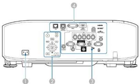
text_image
Diagram of a device rear panel with labeled ports and control panels, showing numbered annotations for identification.| Name Function | ||
| 1 | Power inlet | Connects the power cord to the projector. |
| 2 | Control panel | “Control Panel” p.18 |
| 3 | Security slot | The security slot is compatible with the Microsaver Security System manufactured by Kensington.“Anti Theft/Fall Prevention” p.119 |
| 4 | Connector Ports | “Connector Ports” p.17 |
Connector Ports
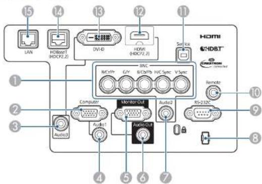
text_image
15 14 13 12 11 LAN HDMI HDXP2.20 一验器图 DV-D HDMI HDXP2.2 Service HDMI HDBT Remote Rs-232C Audio2 Audio1 Audio3 Monitor Out Computer Audio1 Audio Out 1 2 3 4 5 6 7 8 9 10 11| Name Function | ||
| 1 | BNC port | For analog RGB signals from a computer and component video signals from other video sources. |
| 2 | Computer Port | For analog RGB signals from a computer and component video signals from other video sources. |
| 3 | Audio3 port | Inputs audio from equipment connected to the HDMI port or the DVI-D port. |
| 4 | Audio1 port | Inputs audio from equipment connected to the Computer port. |
| 5 | Monitor Out port | Outputs to an external monitor the analog signal from the computer connected to the Computer port or the BNC port. You cannot output signals input from other ports or component video signals. |
| 6 | Audio Out port | Outputs audio from the currently projected image to an external speaker. |
| 7 | Audio2 port | Inputs audio from equipment connected to the BNC port. |
| Name Function | ||
| 8 | Cable holder | Run a commercially available cable tie to secure cables. |
| 9 | RS-232C port | When controlling the projector from a computer, connect it to the computer with an RS-232C cable. This port is for control use and should not normally be used.➤ "ESC/VP21 Commands" p.226 |
| 10 | Remote port | Connects the optional remote control cable set and inputs signals from the remote control. When the remote control cable is plugged into the Remote port, the remote receiver on the projector is disabled.➤ "Optional Accessories and Consumables" p.233 |
| 11 | Service port | This is used for batch settings. This port is for control use and should not normally be used.➤ "Batch Setup" p.164 |
| 12 | HDMI port | Inputs video signals from HDMI compatible video equipment and computers. |
| 13 | DVI-D port | Inputs the computer DVI-D signals. |
| 14 | HDBaseT port | Connects a LAN cable to the optional HDBaseT Transmitter.➤ "Connecting an HDBaseT Transmitter" p.53➤ "Optional Accessories and Consumables" p.233 |
| 15 | LAN port | Connects a LAN cable to connect to a network. |
Base
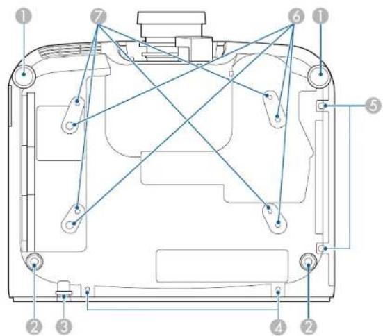
text_image
Technical diagram of a device casing with numbered components and connecting lines indicating assembly or connection points.| Name Function | ||
| 1 | Front feet | When setup on a surface such as a desk, extend and retract the feet to adjust the height or tilt of the image."Adjusting the Height of the Projected Image (for Normal Installment)" p.41"Adjusting the Horizontal Tilt (for Normal Installment)" p.42 |
| 2 | Rear feet | |
| 3 | Security cable Installation point | Pass a commercially available anti-theft wire lock or a wire to prevent the projector from falling through here and lock it in place."Anti Theft/Fall Prevention" p.119 |
flowchart
graph TD
    A["On"] --> B["Standby"]
    C["Menu"] --> D["Exc"]
    E["Enter"] --> F["Lens"]
    G["A/V Mute"] --> H["Home Position (Base)"]
    style A fill:#f9f,stroke:#333
    style B fill:#ccf,stroke:#333
    style C fill:#cfc,stroke:#333
    style D fill:#fcc,stroke:#333
    style E fill:#cff,stroke:#333
    style F fill:#ffc,stroke:#333
    style G fill:#fcc,stroke:#333
    style H fill:#ffc,stroke:#333
| Name Function | ||
| 4 | Screw holes to fix the cable cover | Screw holes to fix the cable cover in place.◆ "Attaching the Cable Cover" p.55 |
| 5 | Air filter cover fixing screw | Screws to fix the air filter cover in place. |
| 6 | Ceiling mount fixing points (ELPMB47/ELPMB48, 4 points) | Attach the optional ceiling mount here when suspending the projector from a ceiling.◆ "Installing the Projector" p.27◆ "Optional Accessories and Consumables" p.233 |
| 7 | Ceiling mount fixing points (ELPMB22, 4 points) | |
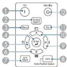
Control Panel
| Name Function | ||
| 1 | [button] | Turns the projector on. |
| 2 | [Source Search] button | Changes to the next input source that is sending an image."Automatically Detecting Input Signals and Changing the Projected Image (Source Search)" p.61 |
| 3 | [Menu] button | Displays and closes the Configuration menu."Configuration Menu Operations" p.136 |
| 4 | [ ]Button | ·When the Configuration menu or the Help screen is displayed, it accepts and enters the current selection and moves to the next level.·If pressed while projecting analog RGB signals from the Computer port or the BNC port, you can automatically optimize Tracking, Sync., and Position. |
| 5 | [ ] Buttons | ·Displays the Control Panel Lock screen allowing you to make settings to lock the control panel buttons. "Restricting Operation" p.117·If pressed when the Configuration menu or the Help screen is displayed, this button selects menu items and setting values. "Configuration Menu Operations" p.136 "Using the Help" p.173 |
| 6 | [ ] Buttons | ·Displays a test pattern. "Displaying the Test Pattern" p.33·If pressed when the Configuration menu or the Help screen is displayed, this button selects menu items and setting values. "Configuration Menu Operations" p.136 "Using the Help" p.173 |
| 7 | [A/V Mute] button | Turns the video and audio on or off. "Hiding the Image and Sound Temporarily (A/V Mute)" p.102 |
| 8 | [Lens] button | Displays the adjustment screens for lens shift, zoom, focus, and distortion in that order each time the button is pressed.If pressed for more than three seconds, the lens position moves to the home position. |
| Name Function | ||
| 9 | [] buttons | Displays the Info menu from the Configuration menu."Info Menu (Display Only)" p.161If pressed when the Configuration menu or the Help screen is displayed, this button selects menu items and setting values."Configuration Menu Operations" p.136"Using the Help" p.173 |
| 10 | [] buttons | Performs screen adjustments using the settings in Geometry Correction from the Configuration menu.Settings - Geometry Correction p.143If pressed when the Configuration menu or the Help screen is displayed, this button selects menu items and setting values."Configuration Menu Operations" p.136"Using the Help" p.173 |
| 11 | [Esc] button | Stops the current function.If pressed when the Configuration menu is displayed, it moves to the previous menu level."Configuration Menu Operations" p.136 |
| 12 | [∅] button | Turns the projector off. |
Remote Control

text_image
On Standby Search HDMI HDBase DVI-D Computer BNC LAN SDI Auto Aspect Lab Note Rest Pattern Freeze Split Lens Shift Zoom Focus Menu Distortion Esc /S uV Mode Default Page Volume E-Zoom i Geometry Memory Word 1 Name: Number 1 2 3 4 5 6 7 8 9 ID 0 Num ID ON O/F Home EPSON Projector| Name Function | ||
| 1 | [1] button | Turns the projector on. |
| 2 | [0] button | Turns the projector off. |
| 3 | Change input buttons | Changes to images from each input port."Switching to the Target Image by Remote Control" p.62The [SDI] button is unavailable. |
| 4 | [Aspect] button | Each time the button is pressed, the aspect mode changes."Changing the Aspect Ratio of the Projected Image" p.80 |
| 5 | [Auto] button | If pressed while projecting analog RGB signals from the Computer port or the BNC port, you can automatically optimize Tracking, Sync., and Position. |
| 6 | [Freeze] button | Images are paused or unpaused."Freezing the Image (Freeze)" p.103 |
| 7 | [Test Pattern] button | Displays a test pattern."Displaying the Test Pattern" p.33 |
| 8 | [Lens Shift] button | Press to adjust the lens shift."Adjusting the Position of the Projected Image (Lens Shift Adjustment)" p.34If pressed for more than three seconds, the lens position moves to the home position. |
| 9 | [Zoom] button | Press to adjust the zoom."Adjusting the Image Size" p.37 |
| 10 | [Menu] button | Displays and closes the Configuration menu."Configuration Menu Operations" p.136 |
| 11 | [ ] [ ] ▶buttons | •Press to adjust focus, zoom, distortion, and lens shift. ◆ "Adjusting the Position of the Projected Image (Lens Shift Adjustment)" p.34 ◆ "Adjusting the Image Size" p.37 ◆ "Correcting the Focus" p.38 •When the Configuration menu or the Help screen is displayed, pressing these buttons selects menu items and setting values. ◆ "Configuration Menu Operations" p.136 |
| 12 | [ ] button | When the Configuration menu or the Help screen is displayed, it accepts and enters the current selection and moves to the next level. ◆ "Configuration Menu Operations" p.136 |
| 13 | [A/V Mute] button | Turns the video and audio on or off. ◆ "Hiding the Image and Sound Temporarily (A/V Mute)" p.102 |
| 14 | [Page] buttons [+] [+] | •Press to change the test pattern while a test pattern is displayed. •Moves to the previous or next image file when projecting images from a computer connected via a network. |
| 15 | [Volume] buttons [+] [<0] | [+] decreases the volume. [+] increases the volume. ◆ "Adjusting the Volume" p.63 |
| 16 | [ ] button | Displays the Info menu from the Configuration menu. ◆ "Info Menu (Display Only)" p.161 |
| 17 | [User1] button [User2] button [User3] button | Select any frequently used item from the Configuration menu items, and assign it to any of these buttons. By pressing the button, the assigned menu item selection/adjustment screen is displayed, allowing you to make one-touch settings/adjustments. ◆ "Settings Menu" p.143 |
| Name Function | ||
| 18 | Numeric buttons | ●Enter the Password.⇨"Setting Password Protection" p.115●Use this button to enter numbers in Network settings from the Configuration menu. |
| 19 | [ID] button | Hold down this button and press the numeric buttons to select the ID for the projector you want to operate using the remote control.⇨"ID Settings" p.42 |
| 20 | [ID] switch | Use this switch to enable (On)/disable (Off) ID settings for the remote control.⇨"ID Settings" p.42 |
| 21 | Remote port | Connects the optional remote control cable set and outputs signals from the remote control.⇨"Optional Accessories" p.233When the remote control cable is plugged into this remote port, the remote control light-emitting is disabled. |
| 22 | [→button | Displays and closes the Home screen.⇨"Home Screen" p.59 |
| 23 | [Num] button | Hold down this button and press the numeric buttons to enter passwords and numbers.⇨"Setting Password Protection" p.115 |
| 24 | [Geometry] button | Corrects distortion in the projected image.⇨"Correcting Distortion in the Projected Image" p.64 |
| 25 | [Memory] button | Performs operations and makes settings for the memory function.⇨"Memory Function" p.110 |
| 26 | [E-Zoom] buttons [⊕][⊖] | Enlarges or reduces the image without changing the projection size.⇨"Enlarging Part of the Image (E-Zoom)" p.104 |
| 27 | [Default] button | Enabled when [Default]: Reset is displayed on the configuration menu guide. The settings being adjusted are returned to their default values.➤ "Configuration Menu Operations" p.136 |
| 28 | [Esc] button | ●Stops the current function.●If pressed when the Configuration menu is displayed, it moves to the previous level.➤ "Configuration Menu Operations" p.136 |
| 29 | [Focus] button | Each time the button is pressed, the adjustment screens for focus and distortion are displayed in that order.➤ "Correcting the Focus" p.38 |
| 30 | [Split] button | Each time the button is pressed, the image changes between projecting two images simultaneously by splitting the projected screen, or projecting one image as normal.➤ "Projecting Two Images Simultaneously (Split Screen)" p.99 |
| 31 | [Color Mode] button | Each time the button is pressed, the Color Mode changes.➤ "Selecting the Projection Quality (Selecting Color Mode)" p.76 |
| 32 | [Search] button | Changes to the next input source that is sending an image.➤ "Automatically Detecting Input Signals and Changing the Projected Image (Source Search)" p.61 |
| 33 | [ ]button | Illuminates the buttons on the remote control for approximately 15 seconds. This is useful when using the remote control in the dark. |
| 34 | Indicator | A light is emitted when outputting remote control signals. |
| 35 | Remote control light-emitting area | Outputs remote control signals. |
Handy remote control operations
You can perform the following operations by simply pressing one of the buttons on the remote control.
| Operation Set | |
| Reverse the projected image vertically.(Switch the Projection between Front and Front/Ceiling)◆ "Changing the direction of the image(projection mode)" p.31 | Hold down the [A/V Mute] button for more than five seconds. |
| Selecting the password security settings.◆ "Managing Users (Password Protection)" p.115 | Hold down the [Freeze] button for more than five seconds. The Password Protection screen is displayed, and you can select various settings. |
| Locking or unlocking some of the operation of the buttons on the remote control.◆ "Remote control button lock" p.118 | Hold down the [▲] button for more than five seconds. |
| Initializing the settings for the Remote Receiver in the Configuration menu.(Enables all Remote receivers for this projector.) | Hold down the [Menu] button for more than 15 seconds. |
Part Names and Functions

| Operation Set | |
| Displaying frequently used Configuration menu items. | Press the [User1], [User2], or [User3] button. You can set the menu item you want to assign to each button in User Button. ⚪ Settings - User Button p.143The following items can be assigned.Light Source Mode, Multi-Projection, Resolution, On-Screen Display, Display the QR Code, Image Enhancement, Frame Interpolation, Link Menu, Content Playback, USBWhen you press the button for which On-Screen Display is assigned, menus or messages are not displayed on the screen. When the same button is pressed, they are displayed again. If On-Screen Display is enabled, you cannot operate the Configuration menu (except to switch the color mode and input source). |
Replacing the remote control batteries
If delays in the responsiveness of the remote control occur or if it does not operate after it has been used for some time, it probably means that the batteries are becoming flat. When this happens, replace them with new batteries. Have two AA size alkaline or manganese batteries ready. You cannot use other batteries except for the AA size alkaline or manganese.
Attention
Make sure you read the following manual before handling the batteries.
Safety Instructions
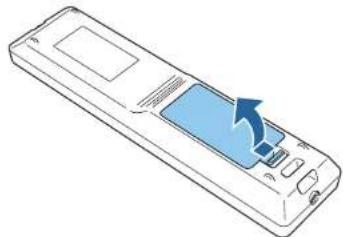
1 Remove the battery cover.
While pushing the battery compartment cover catch, lift the cover up.
natural_image
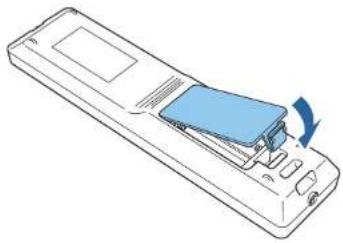
Illustration of a remote control device with a blue scroll and arrow indicating action (no text or symbols)2 Replace the old batteries with new batteries.

natural_image
Line drawing of a remote control casing with battery terminals and internal components (no text or symbols)
Caution
Check the positions of the (+) and (-) marks inside the battery holder to ensure the batteries are inserted the correct way.
If the batteries are not used correctly, they could explode or leak causing a fire, injury, or damage to the product.

Replace the battery cover.
Press the battery compartment cover until it clicks into place.
natural_image
Line drawing of a remote control device with a blue internal component and a blue scroll wheel (no text or symbols)Remote control operating range

text_image
30m 15m 60° 60° 15m 30m 15m 30° 30° 15m 30m 20° 30° 20m 30m 20m 10° 20° 20m 30m
To restrict reception of the operation signals from the remote control, set Remote Receiver.
Settings - Remote Receiver p.143
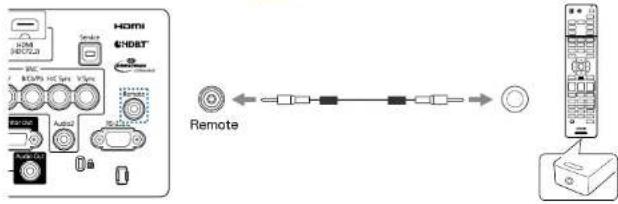
Connecting a cable to the remote control
You can make operations securely with the optional remote control cable set when you use multiple units of this projector in the same place or when there are obstacles around the remote receiver.
"Optional Accessories" p.233
text_image
HDMI 4NDBT Spike B2C M3/MP HD Type V1Type Audio Audio OUT Remote Remote
- When the remote control cable is plugged into the Remote port, the remote receiver on the projector is disabled.
- You can also connect the optional HDBaseT transmitter and remote control with the cable to control the projector.
"Connecting an HDBaseT Transmitter" p.53

Preparing the Projector
This chapter explains how to install the projector and connect projection sources.
Removing and Attaching the Projector Lens Unit

Warning
Make sure you disconnect the power cord from the projector before removing or attaching the lens unit to the projector. Otherwise, it could cause an electric shock.
Attaching
Attention
- Do not attach the lens unit when the projector's lens insertion section is facing up. Dust or dirt could enter the projector.
- Try not to touch the lens section with your hand or fingers. If fingerprints or oils are left on the surface of the lens, projection quality deteriorates.

•The projector supports lens with the following model numbers.
ELPLX01, ELPLX01W, ELPLU03, ELPLU04, ELPLW05, ELPLW06, ELPLW08, ELPLM08, ELPLM09, ELPLM10, ELPLM11, ELPLM15, ELPLL08, ELPLS04, ELPLU02, ELPLR04, ELPLW04, ELPLM06, ELPLM07, ELPLL07
When using the following lens, set the Lens Type in the Configuration menu according to the lens you are using so that distortion correction is performed correctly.
ELPLS04, ELPLU02, ELPLR04, ELPLW04, ELPLM06, ELPLM07, ELPLL07
Extended - Operation - Advanced - Lens Type p.146
- In a normal installation, the image may be tilted depending on your lens. Adjust the tilt of the image using the front and rear feet.
- "Adjusting the Horizontal Tilt (for Normal Installment)"
p.42
- For information on installing ELPLX01/ELPLX01W, see the User's Guide supplied with ELPLX01/ELPLX01W.
1 Pull the lens replacement cover straight out.

natural_image
Illustration of a hand inserting a blue plastic component into a rectangular device (no text or symbols visible)2 Release the lock lever if it is locked.
text_image
ASO Lock3 Pinch the lever, and then move it counter-clockwise.
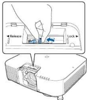
text_image
Release Lock
When using the following lens, attach the supplied lens connector cap to protect the port.
ELPLS04, ELPLU02, ELPLR04, ELPLW04, ELPLM06, ELPLM07, ELPLL07
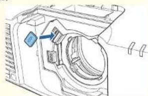
natural_image
Technical line drawing of a mechanical component with no visible text or symbols4 Insert the lens unit straight into the lens insertion section with the white circle on the lens on top.

text_image
Diagram showing a device with a magnified inset of its internal structure, labeled in Chinese.5 While holding the lens unit firmly, pinch the lever and turn it clockwise to lock the lens unit.
Check that the lens cannot be detached.

text_image
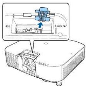
Release Lock6 Secure the lever with the lever lock to make sure it does not come loose.
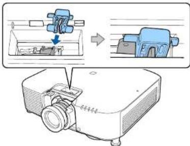
text_image
Diagram illustrating a projector setup with labeled components and process flow, showing mechanical assembly and component positioning.
The lever is secured even without using the lever lock, but this adds an additional measure of safety.
7 Attach the lens replacement cover.
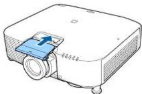
natural_image
Illustration of a projector with a blue cover and cable, no text or symbols present
When projecting down, we recommend securing the front cover with commercially available screws (M3 x 8 mm).

text_image
Technical diagram showing front and side views of a projector with labeled components and cable connectionsLens Calibration
After replacing the lens unit, calibrate the lens so that the projector can correctly acquire the lens position and adjustment range.
After attaching a different lens unit from the previous one, a message is displayed when the projector is turned on.
Select Yes to calibrate the lens.
Lens calibration takes up to about 100 seconds until it is complete. When it is complete, the lens position returns to the position before calibration (ELPLX01/ELPLX01W returns to the standard position).
Attention
If the message "Lens Calibration failed." is displayed, remove the lens unit and then reinstall it. If the message continues to be displayed, stop using the projector, remove the power plug from the electrical outlet, and contact your local dealer or the nearest address provided in the Epson Projector Contact List.
Epson Projector Contact List

- You can perform lens calibration using one of the following methods.
- Press the [Default] button on the remote control for three seconds or more.
- Configuration Menu
Extended - Operation - Lens Calibration p.146
- If no message is displayed after attaching the lens unit, perform lens calibration from the Configuration menu.
- If you do not calibrate the lens, the following functions may not operate correctly.
Focus, Distortion, Zoom, Lens Shift, Memory (Lens Position)
Removing

Caution
Wait for a while after turning off the projector before removing the lens unit (Approx. 30 mins.). Touching the lens unit immediately after projecting or turning off may cause burns.
Attention
If the lens shift has been done, move the lens position to the home position before replacing the lens unit.
"Adjusting the Position of the Projected Image (Lens Shift Adjustment)" p.34

The projector uses a laser as the light source. As a safety measure, the light source turns off when the lens is removed. Attach the lens, and then press the ⑪ button to turn it back on.
1 Pull the lens replacement cover straight out.

natural_image
Diagram of a device with a blue component inserted into a housing, connected to wires (no text or symbols visible)2 If the lock lever has been secured with a stopper, remove the stopper.

text_image
ase Lock3 While holding the lens unit firmly, hold the lock lever and turn it counterclockwise to unlock the lens unit. Pull the lens unit straight out as it is released.

text_image
Release Part Lock ① ②Installation Settings
Changing the direction of the image (projection mode)
You can change the direction of the image using Projection mode from the Configuration menu.
Extended - Projection p.146
When Front is the standard, the image directions for each projection mode are as follows.
Front (default) Front/Ceiling

natural_image
City skyline with modern skyscrapers under a clear blue sky, no visible text or signageRear Rear/Ceiling

natural_image
City skyline with modern high-rise buildings reflected in a clear blue sky (no text or symbols visible)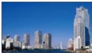
natural_image
City skyline with modern skyscrapers under a clear blue sky (no visible text or signage)
natural_image
Cityscape with modern high-rise buildings reflected in a clear blue sky (no visible text or symbols)
- You can change the setting as follows by pressing down the [A/V Mute] button on the remote control for about five seconds.
Front ↔ Front/Ceiling
Rear Rear/Ceiling
- To rotate the menu display, set OSD Rotation in the Configuration menu.
Extended - Display - OSD Rotation p.146
Screen Settings
Set the Screen Type according to the aspect ratio of the screen being used. The area where the image is displayed matches the shape of the screen.

The settings for the Screen Type at the time of purchase are as follows:
•WUXGA/WXGA projector: 16:10
•XGA projector: 4:3
1 Press the Menu button while projecting. ◆ "Configuration Menu Operations" p.136
2 Select Display from Extended.
3 Select Screen Type from Screen.
4 Select the screen's aspect ratio. The shape of the background test pattern changes depending on the setting.
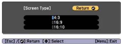
text_image
[Screen Type] 4:3 16:9 16:10 Return [Esc] / [◆]: Return [◆]: Select [Menu]: Exit5 Press the Menu button to finish making settings.

- When you change the Screen Type, adjust the aspect ratio for the projected image as well.
"Changing the Aspect Ratio of the Projected Image" p.80
- The Message Broadcasting function for Epson Projector Management does not support this function.
Adjusting the position of the image on the projected screen
You can adjust the position of the image if there are margins between the edge of the image and the projected screen frame due to the Screen Type setting.
Example: When the Screen Type is set to 4:3 for the WUXGA/WXGA projector

natural_image
Blue square with two white arrows pointing left and right, no text or symbols presentYou can move the image to the left and right.
1 Press the Menu button while projecting.
"Configuration Menu Operations" p.136
2 Select Display from Extended.
3 Select Screen Position from Screen.
4 Use the [▲], [▼], [◀], and [▶] buttons to adjust the position of the image.
You can check the current display position by using the background test pattern.

text_image
[Screen Position] Shift Direction: Top 0Esc:Return [◀◆▶]:Move Menu:Exit
5 Press the Menu button to finish making settings.

The Screen Position cannot be adjusted in the following situations.
- If you are using a WUXGA/WXGA projector and the Screen Type is set to 16:10
- If you are using an XGA projector and the Screen Type is set to 4:3
Displaying the Test Pattern
A test pattern can be displayed to adjust the projection status without connecting video equipment.
The shape of a test pattern is according to the setting of Screen Type. Set Screen Type first.
"Screen Settings" p.32
1 Press the [Test Pattern] button of the remote control or the 📄 button on the control panel while projecting.
2 Press the [◀][▶] buttons on the remote control or the [◀] button on the control panel to change the test pattern.
Using the remote control Using the control panel


text_image
Standard Cross-hatching Cross-hatching B Color Bars V Color Bars H Grayscale Gray Bars V Gray Bars H White Black 4:3 Aspect Frame Cross-hatching R Cross-hatching G Checkerboard 1 Checkerboard 2 16:10 Aspect Frame 16:9 Aspect Frame
- To set menu items that cannot be set while the test pattern is being displayed or to fine-tune the projected image, project an image from the connected device.
- During image adjustment, press the [Page] buttons [↑] [↓] on the remote control to change the test pattern.
- You can also select a test pattern from the Configuration menu.
Settings - Test Pattern p.143

Press the Esc button to close the test pattern.
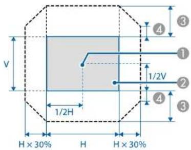
Adjusting the Position of the Projected Image (Lens Shift Adjustment)
The lens can be shifted to adjust the position of the projected image, for example, when the projector cannot be installed directly in front of the screen.
The ranges within which the image can be moved are shown below. The position of the projected image cannot be moved to both the horizontal and vertical maximum values.
EB-L1075U/EB-L1070U/EB-L1065U/EB-L1060U/EB-L1050U/EB-L1070W/EB-L1060W

text_image
V 1/2H H × 30% H H × 30% 1/2V 4 3 ① ② ③ ④1 Center of lens
② Projected image when the lens position is moved to the home position
③ Maximum motion range: V x 67%
4 When the horizontal direction is at the maximum value: V x 19%
EB-L1070
text_image
V 1/2V 1/2H H × 30% H H × 30% ① ② ③ ④① Center of lens
② Projected image when the lens position is moved to the home position
③ Maximum motion range: V x 57%
4 When the horizontal direction is at the maximum value: V x 16%
When using ultra-short focus lens ELPLX01/ELPLX01W
EB-L1075U/EB-L1070U/EB-L1065U/EB-L1060U/EB-L1050U/EB-L1070W/EB-L1060W

text_image
V 1/2H H × 10% H H × 10% ① ② ③① Center of lens
② Projected image for positional reference
③ Maximum motion range: V x 17%
* When the horizontal direction is at the maximum value, the image cannot be moved up.
EB-L1070
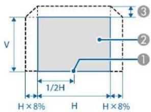
text_image
V 1/2H H × 8% H H × 8% ① ② ③① Center of lens
② Projected image for positional reference
③ Maximum motion range: V x 7%
* When the horizontal direction is at the maximum value, the image cannot be moved up.

- When adjusting the image height with the vertical lens shift, adjust by moving the image from the bottom to the top. If it is adjusted from the top to the bottom, the image position may move down slightly after adjusting.
- We recommend setting the focus, zoom, and lens shift at least 20 minutes after you start the projection. After projecting videos, we recommend waiting for more than 20 minutes to make settings for the Focus/Zoom/Lens Shift.
•The image will be clearest when the lens position is moved to the home position. - If you hold down the [Lens Shift] button on the remote control or the [Lens] button on the control panel for at least three seconds, the lens position moves to the home position.
- If you set A/V Output to Always On, you can move the lens position to the home position even if the projector is in standby mode.
Extended - A/V Settings - A/V Output p.146
- ELPLR04 does not support lens shift.
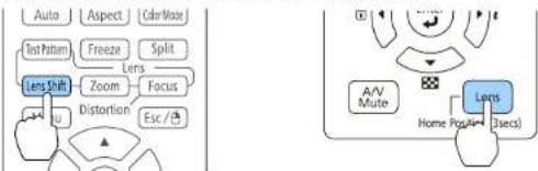
1 Press the [Lens Shift] button on the remote control or the [Lens] button on the control panel.
Repeatedly press the |Lens| button on the control panel until the lens shift adjustment screen is displayed.
Using the remote control Using the control panel
flowchart
graph TD
    A["Auto"] --> B["Aspect"]
    B --> C["Car Mass"]
    D["Text Pattern"] --> E["Freeze"]
    E --> F["Split"]
    G["Lens Shift"] --> H["Zoom"]
    H --> I["Focus"]
    J["EU"] --> K["Distortion"]
    K --> L["Esc /"]
    M["A/V Mute"] --> N["Lens"]
    N --> O["Home Post"]
    N --> P["3secs"]
Installing the Projector

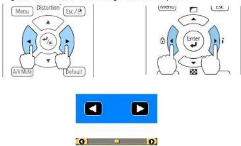
2 Press the [▲][▼][◀][▶] buttons to adjust the position of the projected image.
Using the remote control Using the control panel

flowchart
graph TD
    subgraph LeftPanel
        A["Menu"] --> B["Distortion"]
        B --> C["Esc /"]
        D["A/V Mute"] --> E["Default"]
    end
    subgraph RightPanel
        F["A/V Mute"] --> G["Lens"]
        G --> H["Position (3secs)"]
    end
    I["Video Display"] --> J["0 0 0 0 0 0 0 0 0 0 0 0 0 0 0 0 0 0 0 0 0 0 0 0 0 0 0 0 0 0 0 0 0 0 0 0 0 0 0 0 0 0 0 0 0 0 0 0 0 0 0"]
    end
The displayed screen may differ depending on your lens.
3 Press the Esc button to finish the adjustment.
Adjusting the Image Size

This is not available for ELPLX01, ELPLX01W, and ELPLR04.
1 Press the [Zoom] button on the remote control or the [Lens] button on the control panel.
Repeatedly press the [Lens] button on the control panel until the zoom adjustment screen is displayed.
Using the remote control Using the control panel

text_image
Auto Aspect Color Test Pattern Freeze Split Lens Shift Lens Focus Menu Distribution Esc / A/V Mute Home Page (4+ 2secs)2 Press the [ ][ ] buttons to adjust.
Using the remote control Using the control panel

flowchart
graph TD
    A["Menu"] --> B["Distortion"]
    B --> C["Esc"]
    C --> D["AV"]
    D --> E["Mute"]
    E --> F["Default"]
    G["Enter"] --> H["i"]
    H --> I["Esc"]
The displayed screen may differ depending on your lens.
3 Press the Esc button to finish the adjustment.
Correcting the Focus
1 Press the [Focus] button on the remote control or the [Lens] button on the control panel.
Repeatedly press the [Lens] button on the control panel until the focus adjustment screen is displayed.
Using the remote control Using the control panel

flowchart
graph TD
    A["Auto"] --> B["Aspect"]
    B --> C["ColorMode"]
    D["Info Pattern"] --> E["Freeze"]
    E --> F["Lens"]
    G["Lens Shift"] --> H["Zoom"]
    I["Menu"] --> J["Distortion"]
    K["Focus"] --> L["Link"]
    M["A/V Mute"] --> N["Home Pull-A+ 2secs"]
    O["Lens"] --> P["Home Pull-A+ 2secs"]
2 Press the [◀][▶]buttons to adjust.
Using the remote control Using the control panel
flowchart
graph TD
    A["Menu"] --> B["Distortion"]
    B --> C["Esc/✓"]
    C --> D["A/V Paste"]
    D --> E["Default"]
    F["(menu)"] --> G["Enter"]
    G --> H["i"]
    H --> I["Play Button"]
The displayed screen may differ depending on your lens.

When using the following lens, a message prompting you to adjust the distortion (image warping) is displayed. After adjusting the focus, adjust the distortion.
ELPLX01, ELPLX01W, ELPLU03, ELPLU04, ELPLW05, ELPLW08, ELPLU02
"Correcting Distortion (Image Warping)" p.38
3 Press the Esc button to finish the adjustment.
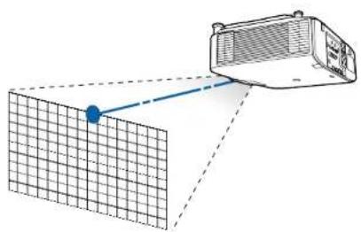
Correcting Distortion (Image Warping)
When using a short throw zoom lens and focusing at the center of the screen, the surrounding image may warp and be out of focus. Follow the steps below to correct the warping.
1 Press the [Focus] button on the remote control or the [Lens] button on the control panel.
Repeatedly press the [Lens] button on the control panel until the focus adjustment screen is displayed.
2 Press the [◀][▶] buttons to focus the image around the center of the lens.
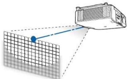
natural_image
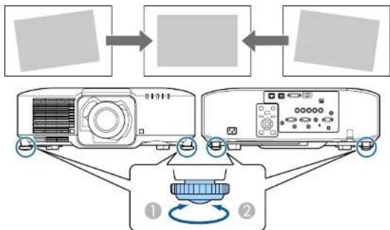
Diagram showing a grid pattern with a blue dot and dashed lines, connected to an air conditioner unit (no text or symbols present)3 Press the [Focus] button on the remote control or the [Lens] button on the control panel again. Repeatedly press the [Lens] button on the control panel until the distortion adjustment screen is displayed.
4 Press the [◀][▶] button to adjust the focus of the surrounding area.
natural_image
Diagram showing a grid plane with a blue dot and a connected air conditioner unit (no text or symbols)
text_image
When using the ELPLU02, a message prompting you to manually adjust the distortion is displayed. Turn the distortion ring counterclockwise, and then adjust the focus. After adjusting the focus, manually turn the distortion ring to correct the image warping.Registering and Loading Lens Adjustment Values
You can register a lens position whose lens shift, zoom, focus, and distortion was adjusted in memory, and load it when necessary. You can register up to 10 values.

- This feature cannot be used if the following lenses are attached. ELPLS04, ELPLU02, ELPLR04, ELPLW04, ELPLM06, ELPLM07, ELPLI07 - If you did not calibrate your lens, a message is displayed when you save a memory. Select Yes to calibrate the lens. - The lens position when a memory is loaded may not completely match the lens position when the memory was saved. - If there is a large discrepancy between the lens position when a memory is loaded and the lens position when the memory was saved, calibrate the lens.
Extended - Operation - Lens Calibration p.146
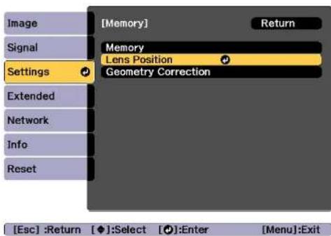
1 Press the [Memory] button while projecting.


You can also operate from the Configuration menu.
Settings - Memory p.143
2 Select Lens Position, and then press the [←] button.
Installing the Projector

text_image
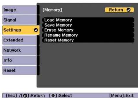
[Memory] Return Signal Settings Lens Position Geometry Correction Extended Network Info Reset [Esc] :Return [◆]:Select [●]:Enter [Menu]:Exit3 Select the function you want to perform, then press the [] button.
text_image
[Memory] Return Load Memory Save Memory Erase Memory Rename Memory Reset Memory Settings Extended Network Info Reset [Esc] / [●]:Return [◆]:Select [Menu]:Exit| Function Explanation | |
| Load Memory | Loads the saved memory. When you select a memory name and press the [←] button, the lens is automatically adjusted according to the settings of the selected memory. |
| Save Memory | Registers current settings in the memory. When you select a memory name and press the [←] button, the settings are saved. |
| Erase Memory | Erases the registered memory. When you select a memory name and press the [←] button, a message is displayed. Select Yes, and then press the [←] button to erase the selected memory. |
| Rename Memory | Changes the memory name. Select the memory name you want to change, and then press the [←] button. Enter the memory name using the soft keyboard. "Soft keyboard operations" p.152When you have finished, move the cursor over Finish, and then press the [←] button. |
Function Explanation
Reset Memory
Resets the name and settings of a saved memory.

If the mark on the left of the memory name is turned blue, it means the memory has already been registered. When you select a registered memory, a message is displayed asking you to confirm that you want to overwrite the memory. If you select Yes, the previous settings are deleted and the current settings are registered.
Adjusting the Height of the Projected Image (for Normal Installment)
Extend or retract the front feet to make adjustments. You can adjust the position of the image by tilting the projector up to 10 degrees.

text_image
Diagram illustrating light refraction and reflection with labeled components and directional arrows① Extend the front feet.
② Retract the front feet.

The larger the angle of tilt, the harder it becomes to focus. Install the projector so that it only needs to be tilted at a small angle.
Adjusting the Horizontal Tilt (for Normal Installment)
Extend and retract the front and rear feet to adjust the projector's horizontal tilt. You can adjust the tilt within a range of ±1.5^ .
flowchart
graph TD
    A["Input"] --> B["Data Input"]
    B --> C["Project Unit"]
    C --> D["Control Unit"]
    D --> E["Output"]
    style A fill:#f9f,stroke:#333
    style B fill:#ccf,stroke:#333
    style C fill:#cfc,stroke:#333
    style D fill:#fcc,stroke:#333
    style E fill:#ffc,stroke:#333
① Extend the front and rear feet.
② Retract the front and rear feet.
Attention
The rear feet are detachable. You can extend the feet by approximately 12 mm before they detach.
ID Settings
When an ID is set for the projector and the remote control, you can use the remote control to operate only the projector with a matching ID. This is very useful when managing multiple projectors. You can set up to 30 IDs.

- Operation using the remote control is possible only for projectors that are within the operating range of the remote control.
"Remote control operating range" p.24 - IDs are ignored when the projector ID is set to Off or the remote control ID is set to 0.
- If you use Epson Web Control, you can operate a specific projector from a mobile device.
"Changing Settings Using a Web Browser (Epson Web Control)" p.215
Set the projector ID
1 Press the Menu button while projecting.
"Configuration Menu Operations" p.136
2 Select Multi-Projection from Extended.
3 Select Projector ID, and then press the [◀] button.
4 Press the [][]buttons to select an ID number.
Installing the Projector


text_image
[Multi-Projection] Projector ID 01 Set [Esc] :Return [◆◆]:Select [Menu]:Exit5 Select Set, and then press the [←] button.
6 Press the Menu button to close the Configuration menu.
Checking the projector ID
During projection, press the [▲ button while holding down the [ID] button.

text_image
Remote control 7 8 9 ID 0 Num 0 Off Home EPSON Projector ID: D2When you press the buttons, the current Projector ID is displayed on the projection screen. It disappears in about three seconds.
Setting the remote control ID
1 Set the remote control [ID] switch to On.

text_image
4 5 6 7 8 9 ID 0 On Off On Off ID On Off2 While holding the [ID] button, press a number button to select a number to match the ID of the projector you want to operate.
"Checking the projector ID" p.43 Enter a two digit number (Example: 01 when the ID is 1).

Once this setting has been made, the projector that can be operated by the remote control is limited.

The remote control ID setting is saved in the remote control. Even if the remote control batteries are removed to replace them and so on, the stored ID setting is retained. However, if the batteries are left out for a long time, it is reset to the default value (ID0).
Setting the Time
You can set the time for the projector. The set time is used for the schedule function.
s "Scheduling Function" p.112

- When you turn on the projector for the first time, the message "Do you want to set the time?" is displayed. When you select Yes, the screen from step 4 is displayed.
- When Schedule Protection is set to On in Password Protection, settings related to the date and time cannot be changed. You can make changes after setting Schedule Protection to Off.
s "Managing Users (Password Protection)" p.115
1 Press the Menu button while projecting.
s "Configuration Menu Operations" p.136
2 Select Operation from Extended.
3 Select Date & Time, and then press the [←] button.
4 Make settings for the date and time.
Use the soft keyboard to enter the date and time.
s "Soft keyboard operations" p.152

text_image
[Date & Time] Return Date & Time Daylight Saving Time Daylight Saving Time Off DST Start DST End DST Adjustment (min) 0 Internet TimeDate & Time
| Submenu Function | |
| Date | Set today's date. |
| Time | Set the current time. |
| Time Difference (UTC) | Set the time difference from Coordinated Universal Time. |
| Set | The settings made in Date & Time are applied. |
Daylight Saving Time
| Submenu Function | |
| Daylight Saving Time | Set whether or not (On/Off) to activate the daylight saving time. DST Adjustment (min) adjusts the time difference between the standard time and daylight saving time. |
| DST Start | Set the date and time to start the daylight saving time. |
| DST End | Set the date and time to end the daylight saving time. |
| Set | The settings made in Daylight Saving Time are applied. |
Internet Time
| Submenu Function | |
| Internet Time | Set to On to update the time automatically through an Internet time server. |
| Internet Time Server | Input the IP address for an Internet time server. |
| Set | The settings made in Internet 'Time are applied. |

When changing settings, make sure you select Settings, and then press the ↻ button.
5 Press the Menu button to finish making settings.
Other Settings
Settings related to basic operations
| Purpose Setting Methods | |
| To start/stop projection by turning on/off the main power or plugging in or unplugging the power plug of the projector. | Set Direct Power On to On. (Default value: Off)Extended - Operation - Direct Power On p.146The projector can be powered off directly by the breaker because it supports the direct shutdown function. |
| To disable the automatic shutdown function. | Set Sleep Mode to Off. (Default value: On)Extended - Operation - Sleep Mode p.146Set A/V Mute Timer to Off.Extended - Operation - A/V Mute Settings - A/V Mute Timer p.146 |
| To disable buzzer beeps generated when the projector is powered on/off. | Set Beep to Off. (Default value: On)Extended - Operation - Advanced - Beep p.146 |
| To operate the projector by communication command even when the power of the projector is off. | Set Standby Mode to Communication On. (Default value: Communication Off)Extended - Standby Modc p.146 |
| To operate the projector by communication command while executing A/V Mute. | Set A/V Mute Release to A/V Mute.Extended - Operation - A/V Mute Settings - A/V Mute Release p.146The default value is Any Button. If you operate the projector while A/V Mute is on, A/V Mute is released. |
| Turn off the power by pressing the [⏻] button once. | Set Standby Confirmation to Off. (Default value: On)Extended - Display - Standby Confirmation p.146 |
Settings related to display
| Purpose Setting Methods | |
| To change the menu position. | Change the settings of Menu Position.➤ Extended - Display - Menu Position p.146 |
| To change the menu direction. | Change the settings of OSD Rotation.➤ Extended - Display - OSD Rotation p.146 |
| To prevent the display of menus, messages, or warnings on the screen. | Use User Button to set On-Screen Display to User Button 1, User Button 2, or User Button 3.➤ Settings - Uscr Button p.143When you press the button for which On-Screen Display is assigned, menus or messages are not displayed on the screen. When the same button is pressed, they are displayed again. If On-Screen Display is enabled, you cannot operate the Configuration menu (except to switch the color mode and input source). |
| To disable the display of the message on the projection screen when switching the source. | Set Messages to Off. (Default value: On)➤ Extended - Display - Messages p.146You can confirm warning by the display of the indicator.➤ "Reading the Indicators" p.175Dialogs related to operations and behaviors, laser warnings, termination of Message Broadcasting for Epson Projector Management, and projector ID are displayed. |
| Purpose Setting Methods | |
| To register and save the settings of the projected image. | Set Memory."Memory Function" p.110You can save the following settings.Memory: Some settings in the Configuration menuLens Position: Adjustment values of the lens shift, zoom, focus, and distortionGeometry Correction: Adjustment value of the geometry correction |
| To change the screen displayed on the background. | Change from Display. You can select from blue, black, and logo. If no logo is registered, the EPSON logo is displayed.Display Background: Set the screen display with no image signal input. (Default value: Blue)Extended - Display - DisplayBackground p.146Startup Screen: Set whether or not (On/Off) to display the user logo when the projector is turned on. (Default value: On)Extended - Display - Startup Screen p.146 |
The port name, location, and connector orientation differ depending on the source being connected.
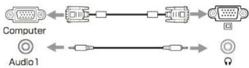
Connecting a Computer
To project images from a computer, connect the computer using one of the following methods.
When using a commercially available computer cable
Connect the computer's display output port to the projector's Computer port.
You can output audio from the Audio Out port on the projector by connecting the audio output port on the computer to the projector's Audio1 port using a commercially available audio cable.
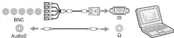
② When using a commercially available 5BNC cable
Connect the computer's display output port to the projector's BNC port.
You can output audio from the Audio Out port on the projector by connecting the audio output port on the computer to the projector's Audio2 port using a commercially available audio cable.
③ When using a commercially available HDMI cable
Connect the HDMI port on the computer to the projector's HDMI port.
You can send the computer's audio with the projected image.
4 When using a commercially available DVI-D cable
Connect the DVI-D port on the computer to the projector's DVI-D port.
You can output audio from the Audio Out port on the projector by connecting the audio output port on the computer to the projector's Audio3 port using a commercially available audio cable.

text_image
LAN HDMI-3 (HDC 2.2) DVI-3 HDMI (HDCPU.2) BNC R/CuPR G/Y BCuPo HC Sync V Sync Service HDMI HDBT Remote Computer Monitor Out Audio1 Audio2 RS-232C Audio3 Audio Out①
text_image
Computer Audio 1②
flowchart
graph LR
    A["BNC"] --> B["Switch"]
    C["Audio2"] --> D["Switch"]
    B --> E["External Connector"]
    D --> E
    E --> F["Laptop with Wave Graph"]
③

flowchart
graph LR
    A["HDMI"] <--> B["HD/UX"]
    B --> C["HDMI OUT"]
    D["DVI-D"] <--> E["HD/UX"]
    E --> F["DVI-D OUT"]
    G["Audio3"] <--> H["HD/UX"]
    H --> I["DVI-D OUT"]
4

- Change the audio output from Audio Settings.
Extended - A/V Settings - Audio Settings p.146 - If audio is not sent using an HDMI cable, connect a commercially available audio cable to the Audio3 port to send the audio. Set HDMI Audio Output to Audio3.
Extended - A/V Settings - Audio Settings - HDMI Audio Output p.146
Connecting Image Sources
To project video images, connect to the projector using one of the following methods.
When using a commercially available component video cable (D-sub/component converter)
Connect the component output port on the image source to the projector's Computer port.
You can output audio from the Audio Out port on the projector by connecting the audio output port on the video equipment to the projector's Audio1 port using a commercially available audio cable.
② When using a commercially available component video cable (RCA) and a BNC/RCA adapter
Connect the component output port on the video equipment to the projector's BNC port (R/Cr/Pr, G/Y, B/Cb/Pb).
You can output audio from the Audio Out port on the projector by connecting the audio output port on the video equipment to the projector's Audio2 port using a commercially available audio cable.
③ When using a commercially available HDMI cable
Connect the HDMI port on the image source to the projector's HDMI port.
You can send the image source's audio with the projected image.

flowchart
graph TD
    A["1: LAN"] --> B["2: HDMI"]
    B --> C["3: HDMI"]
    subgraph Top
        D["1: LAN"] --> E["2: Computer"]
        E --> F["3: Monitor Out"]
        F --> G["4: Audio1"]
        G --> H["5: Audio2"]
        H --> I["6: Audio3"]
        I --> J["7: Audio4"]
        J --> K["8: Audio5"]
        K --> L["9: Audio6"]
        L --> M["10: Audio7"]
        M --> N["11: Audio8"]
        N --> O["12: Audio9"]
        O --> P["13: Audio10"]
        P --> Q["14: Audio11"]
        Q --> R["15: Audio12"]
        R --> S["16: Audio13"]
        S --> T["17: Audio14"]
        T --> U["18: Audio15"]
        U --> V["19: Audio16"]
        V --> W["20: Audio17"]
        W --> X["21: Audio18"]
        X --> Y["22: Audio19"]
        Y --> Z["23: Audio20"]
        Z --> AA["24: Audio21"]
        AA --> AB["25: Audio22"]
        AB --> AC["26: Audio23"]
        AC --> AD["27: Audio24"]
        AD --> AE["28: Audio25"]
        AE --> AF["29: Audio26"]
        AF --> AG["30: Audio27"]
        AG --> AH["31: Audio28"]
        AH --> AI["32: Audio29"]
        AI --> AJ["33: Audio30"]
        AJ --> AK["34: Audio31"]
        AK --> AL["35: Audio32"]
        AL --> AM["36: Audio33"]
        AM --> AN["37: Audio34"]
        AN --> AO["38: Audio35"]
        AO --> AP["39: Audio36"]
        AP --> AQ["40: Audio37"]
        AQ --> AR["41: Audio38"]
        AR --> AS["42: Audio39"]
        AS --> AT["43: Audio40"]
        AT --> AU["44: Audio41"]
        AU --> AV["45: Audio42"]
        AV --> AW["46: Audio43"]
        AW --> AX["47: Audio44"]
        AX --> AY["48: Audio45"]
        AY --> AZ["49: Audio46"]
        AZ --> BA["50: Audio47"]
        BA --> BB["51: Audio48"]
        BB --> BC["52: Audio49"]
        BC --> BD["53: Audio50"]
        BD --> BE["54: Audio51"]
        BE --> BF["55: Audio52"]
        BF --> BG["56: Audio53"]
        BG --> BH["57: Audio54"]
        BH --> BI["58: Audio55"]
        BI --> BJ["59: Audio56"]
        BJ --> BK["60: Audio57"]
        BK --> BL["61: Audio58"]
        BL --> BM["62: Audio59"]
        BM --> BN["63: Audio60"]
        BN --> BO["64: Audio61"]
        BO --> BP["65: Audio62"]
        BP --> BQ["66: Audio63"]
        BQ --> BR["67: Audio64"]
        BR --> BS["68: Audio65"]
        BS --> BT["69: Audio66"]
        BT --> BU["70: Audio67"]
        BU --> BV["71: Audio68"]
        BV --> BW["72: Audio69"]
        BW --> BX["73: Audio70"]
        BX --> BY["74: Audio71"]
        BY --> BZ["HDMI OUT"]
Attention
- If the input source is on when you connect it to the projector, it could cause a malfunction.
- If the orientation or shape of the plug differs, do not try to force it in. The device could be damaged or could malfunction.

- Change the audio output from Audio Settings.
Extended - A/V Settings - Audio Settings p.146
- If audio is not sent using an HDMI cable, connect a commercially available audio cable to the Audio3 port to send the audio. Set HDMI Audio Output to Audio3.
Extended - A/V Settings - Audio Settings - HDMI Audio Output p.146
- If the source you want to connect to has an unusually shaped port, use the cable supplied with the device or an optional cable to connect to the projector.
Connecting External Equipment
You can output images and audio by connecting an external monitor or speaker.
When outputting images to an external monitor
Connect the external monitor to the projector's Monitor Out port using the cable supplied with the external monitor.
② When outputting audio to an external speaker
Connect the external speaker to the projector's Audio Out port using a commercially available audio cable.

text_image
LAN HDBusT HDCP2.2 DX-0 HDMI HXP2.2 Service HDMI HDBT® Connected 3NC 800/91 G/Y B/C/B/Pb H/C Sync V Sync Remote Computer Monitor Out Audio2 RS-232C Audio1 AudioOUT ① Monitor Out D-Sub ② Audio Out Audio IN
- Set A/V Output to Always On to output image even when the projector is in standby mode.
Extended - A/V Settings - A/V Output p.146 - Only analog RGB signals from the Computer port or BNC port can be output to an external monitor. You can set which signals to output in Monitor Out.
Extended - A/V Settings - Monitor Out p.146
Connecting a LAN Cable
Connect a LAN port on network hubs or other equipment to the projector's LAN port with a commercially available 100BASE-TX or 10BASE-T LAN cable.
By connecting a computer to the projector over a network, you can project images and check the status of the projector.
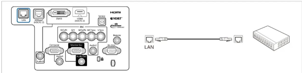
flowchart
graph TD
    subgraph LAN
        A["LAN"] --> B["HDBT HDCF2.2"]
        B --> C["DM-D"]
        C --> D["HDMI HDCF2.2"]
        D --> E["Service"]
        E --> F["HDBT"]
        F --> G["Remote"]
        G --> H["Monitor Out"]
        H --> I["Audio1"]
        H --> J["Audio2"]
        H --> K["Audio3"]
        H --> L["Audio4"]
    end
    subgraph Ethernet
        M["LAN"] <--> N["Internet"]
    end

To prevent malfunctions, use a category 5 or higher shielded LAN cable.
Connecting an HDBaseT Transmitter
Connect the optional HDBaseT Transmitter with a commercially available 100BASE-TX LAN cable.
"Optional Accessories" p.233
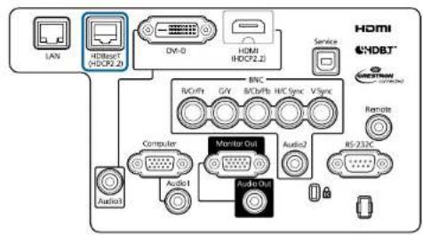
text_image
LAN HD/Base (HDCP2.2) DV-0 HDMI (HDCP2.2) Service HDMI HDBT BNC RVPhi GIV B/CPhi HIC Sync V Sync Computer Monitor Out Audio2 Audio1 Audio1 RS-732K Remote Audio1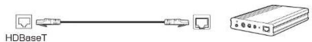
text_image
HDBaseT
- Make sure you read the User's Guide supplied with the HIDBaseT Transmitter carefully before use.
- For the LAN cable, use an HDBaseT' Alliance-recommended STP cable (straight) of category 5c or higher. However, operation is not guaranteed for all input/output devices and environments.
- When connecting or disconnecting the LAN cable, make sure you turn off the power for the projector and the HIDBaseT Transmitter.
- When performing Ethernet communication or serial communication, or when using the wired remote control via HDBaseT port, set Control Communications to On from the Configuration menu.
Extended - HDBaseT - Control Communications p.146
Note that when Control Communications is set to On, the projector's LAN port, RS-232C port, and Remote port are disabled.
- When using the Extron XTP transmitter or switcher, connect to the projector's HDBaseT port. Set Extron XTP to On (Standby Mode and Control Communications are automatically set to On).
Extended - HDBaseT - Extron XTP p.146 - You can check the status of the signal being input to the HDBaseT port in HDBaseT Signal Level.
Info - Projector Info - HDBaseT Signal Level p.161
Installing the Wireless LAN Unit
1 Loosen the fixing screws and open the air filter cover. (You can loosen the screws with your fingers.)
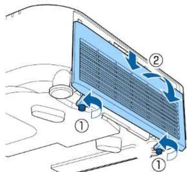
text_image
Diagram showing airflow or ventilation process on a laptop with labeled components and directional arrows2 Use a plus-head screwdriver to loosen and remove the screw from the stopper for the Wireless LAN unit.

text_image
Diagram illustrating a mechanical assembly with labeled parts, showing a component being inserted into a housing and then placed on a platform.3 Install the Wireless LAN unit.

natural_image
Diagram of a refrigerator interior with a blue plastic component inserted, showing no text or symbols4 Secure the stopper with a screw.

natural_image
Diagram showing a computer monitor with an open screen and a magnified view of the screen (no text or symbols present)5 Close the air filter cover and tighten the fixing screws.
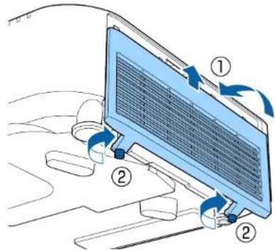
text_image
Diagram showing airflow or ventilation process on a device with numbered annotations indicating steps ① and ②.Attaching the Cable Cover
By attaching the cable cover, you can hide the connected cables giving a nice, clean finish to the projector installation. (The illustrations are of a projector installed on a ceiling.)

Warning
Do not tie the power cord and other connection cables together. Otherwise, it could cause a fire.
Attaching
1 Run a commercially available cable tie through the cable hold and tie the cables together.
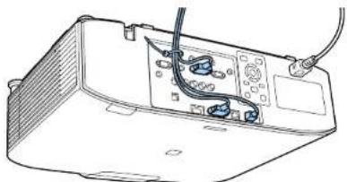
natural_image
Line drawing of an electronic device rear panel with visible ports and wiring (no text or symbols)2 Attach the cable cover to the projector by routing the cables through the grooves in the cable cover.

natural_image
Diagram of a device interior with internal components and directional arrows indicating movement or flow (no text or symbols present)Connecting Equipment

3 Tighten the two screws on the cable cover. (You can tighten the screws with your fingers.)

natural_image
Diagram showing a mechanical assembly with a blue component and a magnified view of the component (no text or symbols present)
Basic Usage
This chapter explains how to project and adjust images.
Turning On the Projector

58
Before turning on the projector, connect your computer or video equipment to the projector.
"Connecting Equipment" p.47
1 Connect the projector to an electrical outlet with the power cord.

natural_image
Diagram showing a cable being inserted into a device with a blue connector (no text or symbols present)The projector's power indicator turns blue (it is in standby mode). This indicates that the projector is receiving power, but is not yet turned on.
2 Press the Ⓐ button on the control panel or remote control to turn on the projector.
The confirmation buzzer beeps and the status indicator flashes blue as the projector warms up. Once the projector is warmed up, the status indicator stops flashing and turns blue.
If the image is not projected, try the following.
- Turn on the connected computer or video equipment.
- When using a laptop computer, change the screen output of the computer.
- Insert media such as a DVD and play it back.
- Press the [Search] button on the control panel or the remote control to detect the input source.
- Press the button for the input source that you want to project by using the remote control.
- If the Home screen is displayed, select the input source that you want to project.

Warning
- Do not look into the projector's lens during projection. Doing so may damage your eyes. Be especially careful if children are present.
- During projection, do not block the light from the projector with a book and so on. If the light from the projector is blocked, the area on which the light shines becomes hot which could cause it to melt, burn, or start a fire. Also, the lens may get hot due to the reflected light which could cause the projector to malfunction. To stop projection, use the A/V Mute function or turn off the projector.

- If Direct Power On is set to On in the Extended menu, the projector automatically turns on when the power cord is connected to it. When the power cord is plugged in, note that the projector turns on automatically in cases such as recovery from a power outage.
Extended - Operation - Direct Power On p.146
- If an image signal from the source selected in Auto Power On is input, the projector automatically turns on.
Extended - Operation - Auto Power On p.146
Home Screen
You can use the Home screen to easily select input sources or frequently used functions. The Home screen is displayed in the following situations.
- When the [↑] button on the remote control is pressed
- When the projector is turned on while Home Screen Auto Disp. is set to On
Extended - Home Screen - Home Screen Auto Disp. p.146
- When there is no signal from the selected input source when the projector is turned on
When the Home screen is displayed, use the | ▲ || | | | buttons on the control panel or remote control to select an item, and then press the [◀] button.
To hide the Home screen, press the [ ] button on the remote control again.
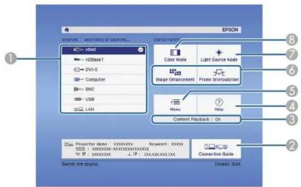
text_image
EPSON Source : searching at source... HDMI HDBase1 DVI-6 Computer BNC USB LAN Userful Hierarchy Color Mode Light Source Mode Image Enhancement Frame Interpolation Menu Help Content Playback : On Projector Name: XXXXXXXX Keyword: XXXXX SSB: XXXXXXXX-XXXXXXXXXXXXX TF IP: XXXXXXXX ↓TF: XXXXXXXXX.XXX Connection Guide Switch the source. [Note]: Exit1 Select the input source that you want to project.
| 2 | Displays the Connection Guide. You can check which wireless connection method to use for your device. |
| 3 | Indicates that the projector is in Content Playback mode. |
| 4 | Displays the Help screen.● "Using the Help" p.173 |
| 5 | Displays the Configuration menu. |
| 6 | Executes the function assigned to Custom Function 1 or Custom Function 2 in the Extended menu.● Extended - Home Screen - Custom Function 1, Custom Function 2 p.146 |
| 7 | Select Light Source Mode.● "Setting the Brightness" p.77 |
| 8 | Select Color Mode.● "Selecting the Projection Quality (Selecting Color Mode)" p.76 |

The Home screen disappears after 10 minutes of inactivity.
Turning Off the Projector


- To ensure a long projector service life, turn off the projector when you are not using it. The light source's operating life varies depending on the Configuration menu settings, environmental conditions, and usage conditions. The brightness of the projected image drops as projection time elapses.
- The projector can be powered off directly by the breaker because it supports the direct shutdown function.
- When the projector is used continuously for more than 24 hours, or when direct shutdown is used regularly, set Light Source Calibration using the scheduling function to adjust the light source periodically. You can also make settings from the Configuration menu.
"Scheduling Function" p.112
Reset - Light Source Calibration p.162
1 Press the [①] button on the control panel or the remote control. The shutdown confirmation screen is displayed.
Power Off?
Yes: Press ⏻ button No : Press any other button
2 Press the [☐] button again. (To cancel, press any other button.) After the buzzer beeps twice, the projected image disappears, and the status indicator turns off.
3 Disconnect the power cord.
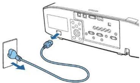
natural_image
Diagram showing a device connected to a cable with blue connectors, no text or symbols presentAutomatically Detecting Input Signals and Changing the Projected Image (Source Search)
Press the [Search] button to project images from the port currently receiving an image.
Using the remote control Using the control panel


When two or more image sources are connected, repeatedly press the [Search] button until the target image is projected.
When your video equipment is connected, start playback before beginning this operation.

- You can set up the projector so that it automatically detects an image signal from another input source and projects the image when there is no image signal from the current input source.
Extended - Operation - Auto Source Search p.146
•The following screen is displayed while no image signals are input.
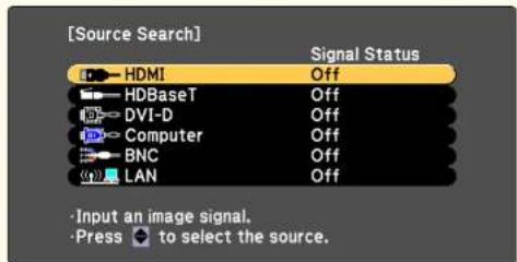
text_image
[Source Search] HDMI Signal Status Off HDBaseT Off DVI-D Off Computer Off BNC Off LAN Off Input an image signal. Press to select the source.
Switching to the Target Image by Remote Control
- Press the button of the input source that you want to project. The input ports for the buttons are shown below.

text_image
Remote control On Standby 0 Search HDMI HDBaseT DVI-D Computer BNC LAN SDI Input Port LAN HDBaseT HDCPZ.20 DV-D DVI-D HDMI HDCPZ.20 Service RxCnPf G/V B/Cb/Pb HCI Sync V/Sync Computer Monitor Out Audio2 RS-232C Audio1 Audio1 Audio2 Remote HDMI HDBT™Changes to images from a computer connected via the network.

When using Content Playback mode, you can switch to the USB source by pressing the User Button assigned to USB.
- Press the [▲ button.

text_image
Remote control 4 5 6 7 8 9 ID 0 Num On Off HomeSelect the input source to be projected, and then press the ↕] button.

text_image
EPSON Sources : Searching all sources... HDN1 HIDaserT DVIL-0 Character BNC USB LAN Useful Functions: Color Mode Light Source Mode Image Enhancement Frame Interpretation Menu Help Content Playback : Or Projector Name: XXXXXXXX Keyword: XXXXX 3510 : XXXXXXXX XXXXXXXXXX IP : XXXXXXXX IP : XXXXXXXX.XXX Network Guide Switch the source. [Down] ExitAdjusting the Volume
You can adjust the volume of the audio from the Audio Out port using one of the following methods.
- Press the [Volume] buttons on the remote control to adjust the volume.
[<0] increases the volume.
[◇] decreases the volume.
Remote control
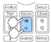
- Adjust the volume from the Configuration menu.
Settings - Volume p.143

Caution
Do not start at high volume.
A sudden excessive volume may cause loss of hearing. Always lower the volume before powering off, so that you can power on and then gradually increase the volume.
Correcting Distortion in the Projected Image
You can correct keystone distortion in projected images using one of the following methods.
•H/V-Keystone
This allows you to correct distortion in the horizontal and vertical directions independently.
"H/V-Keystone" p.65
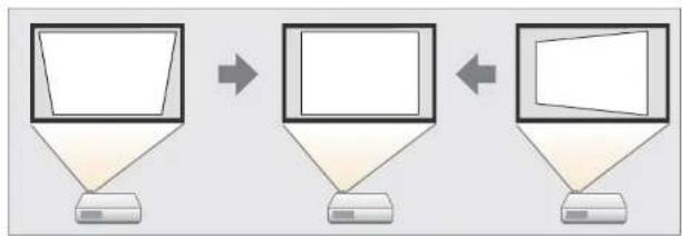
Correct the four corners independently.
"Quick Corner" p.66
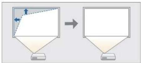
flowchart
graph TD
    A["Computer monitor with left-pointing arrow"] --> B["Computer monitor with right-pointing arrow"]
•Curved Surface
Correct distortion that occurs when projecting on a curved surface, and adjust the amount of expansion and contraction.
"Curved Surface" p.67
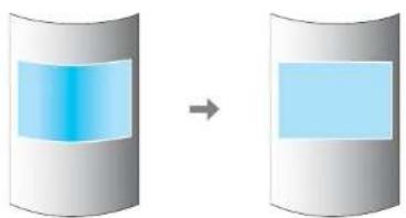
natural_image
Diagram showing a blue rectangular block on the left of a gray cylinder, transitioning to a larger blue rectangle on the right (no text or symbols)•Corner Wall
This allows you to correct distortion that occurs when projecting on a surface with right angles, such as a square pillar or the corner of a room, and adjust the amount of expansion and contraction.
"Corner Wall" p.71

natural_image
Two-step diagram showing a 3D geometric shape transforming into a 2D rectangular prism, with no text or symbols present.- Point Correction
Corrects slight distortion which occurs partially, or adjusts the image position in an overlapping area when projecting from multiple projectors.
"Point Correction" p.74
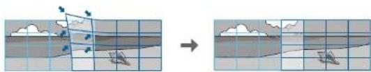
natural_image
Diagram showing a 3D coordinate system with arrows and grid lines, before and after transformation (no text or symbols)
- By pressing the [Geometry] button on the remote control or the [☐] button on the control panel, a screen for selecting the adjustment method is displayed.
- When you want to re-adjust the projection position and so on, if you want to release the correction status temporarily, set the Geometry Correction to Off. Even when it is set to Off, the correction values are saved.
Settings - Geometry Correction p.143 - You can save the geometry correction settings using Memory in Geometry Correction, and load them when needed.
"Memory Function" p.110

text_image
[H/V-Keystone] V-Keystone 0 V-Balance 0 H-Keystone 0 H-Balance 0 ReturnEsc:Return ◆:Select ◆:Adjust Menu:Exit [Default]:Reset
H/V-Keystone
This allows you to correct distortion in the horizontal and vertical directions independently.
Use the following to check the adjustment range for the image.
"H/V-Keystone" p.261
1 Press the Menu button while projecting.
2 Select Geometry Correction from Settings.
3 Select H/V-Keystone, and then press the [◀] button. "If this setting is changed, the image may be distorted." is displayed, press the [◀] button.
4 Use the [▲][▼] buttons to select the correction method, and then use the ▶[]▶ buttons to make the corrections.
Correct the keystone distortion by using V-Keystone and H-Keystone.
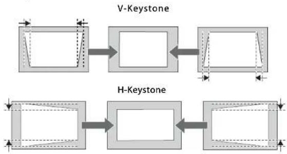
flowchart
graph LR
    A["Rectangular Shape"] --> B["Rectangular Frame"]
    B --> C["Rectangular Frame"]
    D["V-Keystone"] --> E["Rectangular Frame"]
    F["H-Keystone"] --> G["Rectangular Frame"]
    G --> H["Rectangular Frame"]
If the image aspect is incorrect, adjust the image balance by using V-Balance and H-Balance.

flowchart
graph TD
    A["Square Block 1"] <--> B["Square Block 2"]
    C["Square Block 3"] <--> D["Square Block 4"]
    style A fill:#fff,stroke:#000
    style B fill:#fff,stroke:#000
    style C fill:#fff,stroke:#000
    style D fill:#fff,stroke:#000

When you correct keystone distortion, the projected image may be reduced.
5 To complete the corrections, press the Menu button.

You cannot combine with other correction methods.
Quick Corner
This allows you to correct each of the four corners of the projected image independently.
1 Press the Menu button while projecting.
2 Select Geometry Correction from Settings.
3 Select Quick Corner, and then press the [◀] button. "If this setting is changed, the image may be distorted." is displayed, press the [◀] button again.
4 Use the [▲], [▼], [◀], and [▶] buttons to select the corner you want to adjust, and then press the J button.

text_image
[Quick Corner] Select the area.

If the Esc button is pressed for approximately two seconds, the confirm default reset screen is displayed.
Select Yes to reset the result of Quick Corner corrections.
5 Use the [▲], [▼], [◀], and [▶] buttons to correct the position of the corner.
When you press the 📄 button, the screen shown in step 4 that allows you to select the area to be corrected is displayed.
If the message "Cannot adjust any further." is displayed while adjusting, you cannot adjust the shape any further in the direction indicated by the gray triangle.
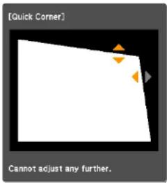
text_image
[Quick Corner] Cannot adjust any further.6 Repeat steps 4 and 5 as needed to adjust any remaining corners.
7 To complete the corrections, press the Menu button.
Curved Surface
This allows you to correct distortion that occurs when projecting on curved surface, and adjust the amount of expansion and contraction.
Face the projector directly opposing the screen with the lens position moved to the home position.
"Adjusting the Position of the Projected Image (Lens Shift Adjustment)" p.34

- Project onto an arc surface with the same radius.
- If a large amount of adjustment is performed, the focus may not be uniform even after making adjustments.
- If 4K Enhancement is enabled, a message is displayed. Select Yes to disable 4K Enhancement. (EB-L1075U/EB-L1070U/EB-L1065U/EB-L1060U/EB-L1050U only)
Image - Image Enhancement - 4K Enhancement p.140
Use the following to check the adjustment range for the image.
"Curved Surface" p.261
1 Press the Menu button while projecting.
2 Select Geometry Correction from Settings.
3 Select Curved Surface, and then press the [←] button.
Adjusting the Projected Images


text_image
[Geometric Correction] Return Off H/V-Keystone Quick Corner Curved Surface Corner Wall Point Correction Memory [Esc]:Return [◆]:Select [●]:Enter [Menu]:Exit"If this setting is changed, the image may be distorted." is displayed, press the |◀| button.
4 Select Curved Surface, and then press the [←] button.
![EPSON EB-L1065UNL - Select Curved Surface, and then press the [←] button. - 1](/content/2026/06/1211104/images/e1f9d6b54ccdb90f7c7624715993ad3d70f3ea5c39ea1f854053e1f69e431e20.jpg)
text_image
[Curved Surface] Return Quick Corner Curved Surface Point Correction Reset [Esc] :Return [◆]:Select [●]:Enter [Menu]:Exit5 Select Correct Shape, and then press the [←] button.
![EPSON EB-L1065UNL - Select Correct Shape, and then press the [←] button. - 1](/content/2026/06/1211104/images/695ef384fdfdb29cd4b076b121079bbd2056e3e97a37cc4bdfbb5c1c81f0f94f.jpg)
text_image
[Curved Surface] Return Correct Shape Horizontal Linearity Vertical Linearity Maintain Aspect Ratio Off [Esc]:Return [◆]:Select [●]:Enter [Menu]:ExitAdjusting the Projected Images

69
6 Use the [▲], [▼], [◀], and [▶] buttons to select the area you want to adjust, and then press the ▶I button.

text_image
[Correct Shape] Select the area.When selecting a corner, you can adjust the two sides next to the corner.

If the Esc button is pressed for approximately two seconds, the confirm default reset screen is displayed.
Select Yes to reset the result of Curved Surface.
7 Use the [▲], [▼], [◀], and [▶] buttons to adjust the shape.
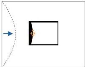
natural_image
Simple diagram showing a dashed arc and a rectangular box with an arrow pointing to it (no text or symbols)If the triangle in the direction you are adjusting the shape turns gray as shown in the screenshot below, you cannot adjust the shape any further in that direction.

natural_image
Simple diagram with a black rectangle and an orange arrow pointing to a white rectangular area (no text or symbols)8 Press the Esc button to return to the previous screen.
9 Repeat steps from 6 to 8 as needed to adjust any remaining parts.
If the image expands or contracts, go to the next step and adjust the linearity.
10 Press the Esc button to display the screen from step 5. Select Horizontal Linearity or Vertical Linearity, and then press the [◀] button.
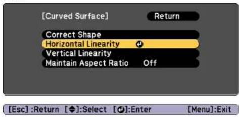
text_image
[Curved Surface] Return Correct Shape Horizontal Linearity Vertical Linearity Maintain Aspect Ratio Off [Esc] :Return [◆]:Select [●]:Enter [Menu]:ExitSelect Horizontal Linearity to adjust the horizontal expansion or contraction, and select Vertical Linearity to adjust the vertical expansion or contraction.

To compensate for expansion or contraction while maintaining the aspect ratio, set Maintain Aspect Ratio to On. You may not be able to perform corrections if you set this to On after correction. In this situation, return the corrections to their initial values, or reduce the amount of correction, and then try again.
11 Select the standard line for the adjustments, and then press the [←] button.
Press the [◀][▶] buttons when selecting Horizontal Linearity, and the [▲][▼] buttons when selecting Vertical Linearity, and then press [◀].
The selected standard line is displayed in flashing orange and white.

Changing the standard line resets the previous settings.
12 Adjust the linearity.
Correct it so that the distance between lines is equal.
When pressing the ▶] button
When Horizontal Linearity is selected When Vertical Linearity is selected
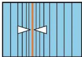
natural_image
Pure diagram of two white arrows pointing inward toward a vertical orange line on a light blue background (no text or symbols)
natural_image
Simple diagram with two white triangles above a horizontal orange line, no text or symbols presentWhen pressing the ▶] button
When Horizontal Linearity is selected When Vertical Linearity is selected

natural_image
Pure geometric diagram with vertical stripes and a central orange line, no text or symbols present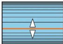
natural_image
Abstract diagram with horizontal lines and two opposing triangles, no text or symbols present13 To complete the corrections, press the Menu button.

You can fine tune the corrected results. Use Quick Corner to adjust the tilt of the image, and then use Point Correction for fine tuning. Select Quick Corner or Point Correction on the screen from step 4.
"Quick Corner" p.66
"Point Correction" p.74
Adjusting the Projected Images

Corner Wall
This allows you to correct distortion that occurs when projecting on a surface with right angles, such as a square pillar or the corner of a room, and adjust the amount of expansion and contraction.
Face the projector directly opposing the screen with the lens position moved to the home position.
"Adjusting the Position of the Projected Image (Lens Shift Adjustment)" p.34

- Project onto a surface with a right angle.
- If a large amount of adjustment is performed, the focus may not be uniform even after making adjustments.
- If 4K Enhancement is enabled, a message is displayed. Select Yes to disable 4K Enhancement. (EB-L1075U/EB-L1070U/EB-L1065U/EB-L1060U/EB-L1050U only)
Image - Image Enhancement - 4K Enhancement p.140
- This is not available for ELPLX01/ELPLX01W.
Use the following to check the adjustment range for the image.
"Corner Wall" p.268
1 Press the Menu button while projecting.
2 Select Geometry Correction from Settings.
3 Select Corner Wall, and then press the [◀] button.

text_image
[Geometric Correction] Return Off H/V-Keystone Quick Corner Curved Surface Corner Wall Point Correction MemoryEsc:Return ◆:Select [●]:Enter Menu:Exit
"If this setting is changed, the image may be distorted." is displayed, press the [◀] button again.
4 Select Corner Wall, and then press the [←] button.

text_image
[Corner Wall] Return Quick Corner Corner Wall Point Correction ResetEsc:Return ◆:Select [●]:Enter Menu:Exit
5 Select Corner Type, and then press the [◀] button.

text_image
[Corner Wall] Return Corner Type ●Horizontal Corner Correct Shape LinearityEsc:Return ◆:Select [●]:Enter Menu:Exit
Adjusting the Projected Images

6 According to the projection area, select Horizontal Corner or Vertical Corner, and then press the button.
When the surfaces line up horizontally:
Select Horizontal Corner.

natural_image
Abstract geometric shape with a vertical dashed line dividing it into two blue rectangles (no text or symbols)When the surfaces line up vertically:
Select Vertical Corner.
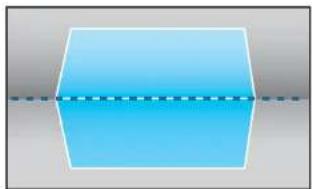
natural_image
Simple geometric shape with a blue hexagon and dashed line, no text or symbols presentFrom here on, steps are explained using Horizontal Corner as an example.
7 Press the Esc button to display the screen from step 5. Select Correct Shape, and then press the button.
8 Adjust the position of the projector and the lens shift so that the line in the center of the screen matches the corner (the point where the two surfaces meet).
"Adjusting the Position of the Projected Image (Lens Shift Adjustment)" p.34

natural_image
Two blue 3D geometric shapes with dashed internal lines, one rotated to form a larger shape (no text or symbols)
Each time you press the [button, you can show or hide the image and the grid.
Adjusting the Projected Images

9 Use the [▲], [▼], [◀], and [▶] buttons to select the area you want to adjust, and then press the J button.

text_image
[Correct Shape] Select the area.Adjustment tips
When Horizontal Corner is selected:
Adjust the upper area based on the lowest point (indicated by the arrow).
Adjust the lower area based on the highest point (indicated by the arrow).
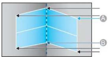
text_image
A BWhen Vertical Corner is selected:
Adjust the left and right based on the point nearest to the vertical line in the center of the screen.

If the Esc button is pressed for approximately two seconds, the confirm default reset screen is displayed. Select Yes to reset the result of Corner Wall.
10 Press the [▲][▼][◀][▶] buttons to adjust the shape.
If the message "Cannot adjust any further." is displayed while adjusting, you cannot adjust the shape any further in the direction indicated by the gray triangle.
11 Repeat steps 9 and 10 as needed to adjust any remaining parts. If the image expands or contracts, go to the next step and adjust the linearity.
12 Press the Esc button to display the screen from step 4. Select Linearity, and then press the I button.

text_image
[Corner Wall] Return Corner Type Horizontal Corner Correct Shape Linearity + [Esc]:Return [◆]:Select [●]:Enter [Menu]:ExitAdjusting the Projected Images


Press the [◀][▶] buttons to adjust the linearity.
Correct it so that the distance between lines is equal.
When pressing the [] button
When Horizontal Corner is selected
When Vertical Corner is selected
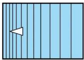
natural_image
Simple diagram with a white triangular shape on a light blue vertical grid background (no text or symbols)
natural_image
Simple diagram with horizontal lines and a small triangle at the top center (no text or symbols)When pressing the ▶] button
When Horizontal Corner is selected
When Vertical Corner is selected
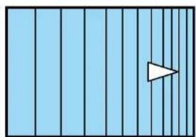
natural_image
Simple diagram with vertical blue bars and a white triangular play button on the right side (no text or symbols)
natural_image
Simple diagram with horizontal lines and a downward-pointing triangle at the bottom (no text or symbols)
To complete the corrections, press the Menu button.

You can fine tune the corrected results. Use Quick Corner to adjust the tilt of the image, and then use Point Correction for fine tuning. Select Quick Corner or Point Correction on the screen from step 4.
"Quick Corner" p.66
"Point Correction" p.74
Point Correction
Divides the projected image by the grid and corrects the distortion by moving the point of intersection from side to side and up and down.

- You can make corrections in 0.5 pixel increments in all directions within the following ranges.
EB-L1075U/EB-L1070U/EB-L1065U/EB-L1060U/EB-L1050U: Vertical and horizontal up to a maximum of 32 pixels.
EB-L1070W/EB-L1060W/EB-L1070: Vertical and horizontal up to a maximum of 20 pixels.
- If 4K Enhancement is enabled, a message is displayed. Select Yes to disable 4K Enhancement. (EB-L1075U/EB-L1070U/EB-L1065U/EB-L1060U/EB-L1050U only)
Image - Image Enhancement - 4K Enhancement p.140

Press the Menu button while projecting.

Select Geometry Correction from Settings.

Select Point Correction, and then press the [←] button.

text_image
[Geometric Correction] Return Off H/V-Keystone Quick Corner Curved Surface Corner Wall Point Correction MemoryEsc:Return ◆:Select [●]:Enter Menu:Exit
Adjusting the Projected Images

"If this setting is changed, the image may be distorted." is displayed, press the [◀] button again.
4 Select Point Correction, and then press the [←] button.

text_image
[Point Correction] Return Quick Corner Point Correction Reset [Esc] :Return [◆]:Select [●]:Enter [Menu]:Exit5 Select Point Correction, and then press the [←] button.

text_image
[Point Correction] Return Point Correction 3x3 Pattern Color White Reset [Esc]:Return [◆]:Select [●]:Enter [Menu]:Exit| Point Correction | Select the point number (3x3, 5x5, 9x9, 17x17), and then make the Point Correction setting. |
| Pattern Color | Select the color of the grid when performing corrections. |
| Reset | Resets all corrections for Point Correction to their default values. |
6 Select the point number (3x3, 5x5, 9x9, or 17x17), and then press the [←] button.

If you reduce the number of points during correction, corrections at the position without a point are reset.
Adjusting the Projected Images

g
Use the [▲], [▼], [◀], and [▶] buttons to move to the point you want to correct, and then press the ◀[ ] button.

natural_image
Illustration of a beach scene with clouds, birds, and a small boat on the water (no text or symbols)h
Use the |▲|, |▼|, |◀|, and |▶| buttons to correct distortion.

natural_image
Diagram showing a mechanical or structural change before and after, with no visible text or symbols.To continue to correct another point, press the Esc button to return to the previous screen, then repeat the steps 7 and 8.

Each time you press the 📁 button, you can show or hide the image and the grid.
i
To complete the corrections, press the Menu button.

You can fine tune the corrected results. Select Quick Corner on the screen from step 4 to adjust the tilt of the image.
"Quick Corner" p.66
Selecting the Projection Quality (Selecting Color Mode)
You can easily obtain the optimum image quality simply by selecting the setting that best corresponds to your surroundings when projecting. The brightness of the image varies depending on the mode selected.
| Mode Application | |
| Dynamic | This is the brightest mode. Ideal for use in a bright room. |
| Presentation | The images are vivid and brought to life. Ideal for making presentations or watching a TV program in a bright room. |
| Natural | Reproduces colors faithfully. Ideal for projecting still pictures such as photos. |
| Cinema | Gives images a natural tone. Ideal for watching films in a dark room. |
| BT.709 | Produces images that conform to the ITU-R BT.709. |
| DICOM SIM | This produces images with clear shadows. Ideal for projecting X-ray photographs and other medical images. The projector is not a medical device and cannot be used for medical diagnosis. |
| Multi-Projection | Minimize the color tone difference between each projected image. Ideal for projecting from multiple projectors. |
Each time you press the |Color Mode| button, the Color Mode name is displayed on the screen and the Color Mode changes.
Remote control


flowchart
graph TD
    A["Presentation"] --> B["Line Chart"]
    B --> C["Output"]

You can set Color Mode from the Configuration menu.
Image - Color Mode p.140
Setting the Brightness
Set the brightness for the light source.
1 Press the Menu button while projecting.
2 Select Brightness Settings from Settings.
3 Select Light Source Mode, and then press the [←] button.
4 Select the item you want to set, and then press the + button.
Normal: Select this if you do not want to decrease the brightness. This makes the light source operation time approximately 20,000 hours.
Medium: Noise from the fan is louder than when Quiet is selected, but it does not decrease the brightness as much. This sets the
brightness at 85%. This makes the light source operation time approximately 20,000 hours.
Quiet: Select this if you are concerned about the noise made by the fan. This sets the brightness at 70%. This makes the light source operation time approximately 20,000 hours.
Extended: Select this to extend the life expectancy of the light source. This sets the brightness at 70%. This makes the light source operation time approximately 30,000 hours.
Custom: Select this to set the Brightness Level manually. When Custom is selected, Constant Brightness is available.
5 When Light Source Mode is set to Custom, select Brightness Level, and then use the ◀||▶ buttons to set the brightness.
6 To maintain a fixed brightness, select Constant Brightness, and set it to On.

- When Constant Brightness is set to On, you cannot change the settings for Light Source Mode and Brightness Level. When you want to change these settings, set Constant Brightness to Off.
- When Constant Brightness is set to Off, the value for Brightness Level changes depending on the current status of the light source.
- There may be a margin of error in the Brightness Level.
- When the projector is used continuously for more than 24 hours, or when direct shutdown is used regularly, set Light Source Calibration using the scheduling function. If this is not set, the Constant Brightness function does not work. You can also make settings from the Configuration menu.
"Scheduling Function" p.112
Reset - Light Source Calibration p.162
Guide to Estimated Remains
When Constant Brightness is set to On, the Estimated Remains is displayed. Estimated Remains indicates the amount of time for which constant brightness can be maintained.
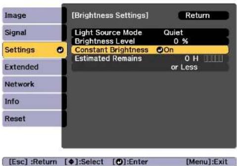
text_image
[Brightness Settings] Return Light Source Mode Quiet Brightness Level 0 % Settings Constant Brightness On Estimated Remains 0 H or Less Extended Network Info Reset [Esc] :Return [◆]:Select [●]:Enter [Menu]:Exit| Display Level Estimated Remains | |
| 10,000 hours or more | |
| 8,000 to 9,999 hours | |
| 6,000 to 7,999 hours | |
| 4,000 to 5,999 hours | |
| 2,000 to 3,999 hours | |
| 0 to 1,999 hours | |

The time displayed on the screen is just a guide. 30,000 hours or more is displayed in units of 10,000; 2,000 to 29,999 hours is displayed in units of 1,000; and up to 1,999 hours is displayed in units of 100.
Relationship between Brightness Level and light source operation time
The following shows the relationship between Brightness Level and the light source operation time.
When Constant Brightness is set to Off
①: Brightness Level
②: Approximate light source operation time until its brightness is reduced by half
| 1 | 2 |
| 100% 20,000 hours | |
| 90% 21,000 hours | |
| 80% 24,000 hours | |
| 70% 30,000 hours | |
| 60% 37,000 hours | |
| 50% 47,000 hours | |
| 40% 61,000 hours | |
| 30% 71,000 hours |
When Constant Brightness is set to On
①: Brightness Level
②: Approximate time for which constant brightness of the light source can be maintained
| 1 | 2 | Illustration |
| 85% 6,000 | hours |  |
| 80% 10,000 | hours | |
| 70% 19,000 | hours | |
| 60% 29,000 | hours | |
| 50% 41,000 | hours | |
| 40% 56,000 | hours | |
| 30% 78,000 | hours |

- This is an approximate guide only and may change depending on the projector's usage and surroundings.
•The times above are the standard hours when using the projector continuously without changing the Brightness Level or Constant Brightness settings and are not guaranteed. - This is an approximate guide only and may change depending on the projector's usage and surroundings. You may need to replace internal parts sooner than the estimated light source operation time.
- When Constant Brightness is set to On, and the approximate constant time has been exceeded, you may not be able to set a high value for Brightness Level.
Setting the Amount of Light of the Projected Image
By automatically setting the luminance according to the brightness of the displayed image, it lets you enjoy deep and rich images. You can also set the light source to turn off automatically.
1 Press the Menu button while projecting.
2 Select Light Source Control from Image, and then press the [←] button.
3 Select Light Source Control, and then press the [←] button.

text_image
[Light Source Control] Return Signal Light Source Control Off Dynamic Contrast Lights-Out Control Settings Extended Network Info Reset [Esc] :Return [◆]:Select [◆]:Enter [Menu]:Exit4 Select the light source operation according to the image signal, and then press the [1] button.

text_image
[Light Source Control] Return Off Dynamic Contrast Lights-Out Control [Esc] / [◆]:Return [◆]:Select [Menu]:Exit- Off: Select if you do not want to control the light source.
- Dynamic Contrast: Automatically adjust the amount of light when projecting according to the brightness of the image.
- Lights-Out Control: Automatically turns off the light after the set time has elapsed at the specified video level.
5 Press the Esc button to return to the previous screen.
6 If you selected Dynamic Contrast in step 4, make the following settings in Dynamic Contrast.
- Response Speed: Select High Speed to adjust the amount of light as soon as the scene changes.
- Black Level: Set the black level when the brightness level of the image signal is zero. When you select 0%, the light source turns off.
7 If you selected Lights-Out Control in step 4, make the following settings in Lights-Out Control.
- Lights-Out Signal Level: Set the brightness level for the video signal being controlled. After turning off automatically when exceeding the specified image level, it turns on immediately.
- Lights-Out Timer: Set the amount of time before automatically turning off the light source.
8 Press the Menu button to finish making settings.
Changing the Aspect Ratio of the Projected Image
You can change the aspect ratio of the projected image to suit the type, the ratio of height and width, and the resolution of the input signals.
Available aspect modes vary depending on the Screen Type currently set.

- Set the Screen Type before changing the aspect ratio.
"Screen Settings" p.32 - This cannot be changed when Scale Mode is set to Zoom
Display.
Signal - Scale - Scale Mode p.142
Changing methods
Each time you press the [Aspect] button on the remote control, the aspect mode name is displayed on the screen and the aspect ratio changes.

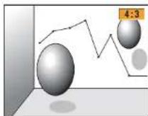
| Aspect Mode Explanation | |
| Auto | Projects in an appropriate aspect ratio based on information from the signal being input. |
| Normal | Projects while retaining the aspect ratio of the input image. |
| 4:3 | Projects at an aspect ratio of 4:3. |
| 16:9 | Projects at an aspect ratio of 16:9. |
Adjusting the Projected Images

| Aspect Mode Explanation | |
| Full | Projects at the full size of the projected screen. |
| H-Zoom | Projects by enlarging the input image to the full width of the projected screen while retaining the aspect ratio. Areas that exceed the edges of the projected screen are not projected. |
| V-Zoom | Projects by enlarging the input image to the full height of the projected screen while retaining the aspect ratio. Areas that exceed the edges of the projected screen are not projected. |
| Native | Projects to the center of the projected screen at the resolution of the input image. Areas that exceed the edges of the projected screen are not projected. |

- The available aspect ratios differ depending on the input signal from the connected device.
- You can also set the aspect ratio from the Configuration menu.
Signal - Aspect p.142
- If parts of the computer image are missing, set the Resolution setting to Wide or Normal from the Configuration menu, according to the resolution of the computer.
Signal - Resolution p.142
Adjusting the Image
Hue, Saturation, and Brightness adjustment
You can adjust the Hue (tint), Saturation (vividness), and Brightness of the six axes R (red), G (green), B (blue), C (cyan), M (magenta), and Y (yellow) according to your preferences.
2 Select Advanced from Image, and then press the [←] button.
3 Select RGBCMY, and then press the [←] button.
4 Use the [▲][▼] buttons to select the color you want to adjust, and then press the ▼ button.

text_image
[RGBCMY] Hue Saturation Return Brightness R 0 0 0 0 G 0 0 0 0 B 0 0 0 0 C 0 0 0 0 M 0 0 0 0 Y 0 0 0 0Esc:Return ◆:Select [○]:Enter Menu:Exit
5 Use the [▲][▼] buttons to select the item, and then use the [◀][▶] buttons to make the adjustments.
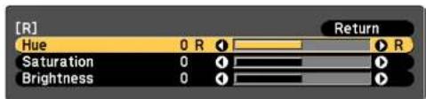
text_image
[R] Hue 0 R Return Saturation 0 Brightness 0Esc:Return ◆:Select [◀]:Adjust Menu:Exit [Default]:Reset [●]:Display
Each time you press the [] button, the adjustment screen changes.
6 To complete the corrections, press the Menu button.
1 Press the Menu button while projecting.
Adjusting the Projected Images

82
Gamma adjustment
You can adjust differences in the halftone brightness that occurs depending on the connected device.

Adjust by projecting a still picture. Gamma cannot be adjusted correctly by using movies.
1 Press the Menu button while projecting.
2 Select Advanced from Image, and then press the [←] button.
3 Select Gamma, and then press the [◀] button.
4 Use the [][] buttons to adjust the value.

text_image
[Gamma] Return Gamma Custom ResetEsc:Return [◀◆▶]:Select [○]:Set Menu:Exit
When a larger value is selected, the dark areas of images become brighter, but the color saturation for lighter areas may become weaker.
When a smaller value is selected, you can reduce the overall brightness of the image to make the image sharper.
If you select DICOM SIM from Color Mode on the Image menu, select the adjustment value according to the projection size.
- If the projection size is 120 inches or less, select a small value. - If the projection size is 120 inches or more, select a large value.

Medical images may not be reproduced correctly according to your installation environment and screen specifications.
5 To make detailed adjustments, select Custom, and then press the [◀] button.
6 Use the [◀][▶] buttons to select the tone that you want to change, and then use the ▶[▶] buttons to make the adjustments. When you have finished making changes, confirm by using the ▶ button.
If you use the ▶ || ▶ buttons to select the tone that you want to change, the image flashes and you can check the tone area of the adjustment target.

text_image
[Gamma] Blinking area is the adjustment target.7 When Do you want to continue adjusting the setting? is displayed, select Yes or No.
To adjust another tone, select Yes, and repeat the procedure from step 6.
Adjusting Image Resolution (Image Enhancement)
You can adjust the resolution of the image using Image Enhancement to reproduce a clear image with an emphatic texture and material feel.
1 Press the Menu button while projecting.
2 Select Image Enhancement from Image, and then press the [←] button.
The following screen is displayed.
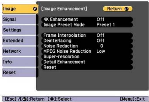
text_image
[Image Enhancement] Signal 4K Enhancement Off Image Preset Mode Preset 1 Settings Frame Interpolation Off Deinterlacing Off Noise Reduction 0 MPEG Noise Reduction Low Super-resolution Detail Enhancement Reset Network Info Reset [Esc] / [●]:Return [◆]:Select [Menu]:Exit4K Enhancement (EB-L1075U/EB-L1070U/EB-L1065U/EB-L1060U/EB-L1050U only)
4K Enhancement is a function that projects an image at a doubled resolution by diagonally shifting 1 pixel in increments of 0.5 pixels.
A high-resolution image signal is projected in fine detail.
1 Select 4K Enhancement from Image Enhancement, and then press the [√] button.
2 Select one of the following, and then press the [] button.
Off: Disables 4K Enhancement. If a signal that exceeds the panel resolution of this projector is input, the image is displayed according to the panel resolution of this projector.
Full HD: If a signal with a resolution of 1080i/1080p/WUXGA or higher is input, 4K Enhancement is enabled.
WUXGA+: If a signal with a resolution that exceeds WUXGA is input, 4K Enhancement is enabled. To project a high-resolution movie, you can project a high-definition image by using this setting with Image Preset Mode.

text_image
[4K Enhancement] Off Full HD WUXGA+ Return- To project from multiple projectors, select Off to unify each image.
- Off is ideal for projecting presentation materials from computers and so on.
- If set to Full HD or WUXGA+, the status corrected using the following function is canceled.
Edge Blending, Scale, Curved Surface, Point Correction, Corner Wall
When 4K Enhancement is set to Off, the settings return to their previous state.
3 Press the Esc button to return to the previous screen.
Image Preset Mode
Select the optimal setting according to the projected image from five presets prepared in advance.
The following settings are saved in the presets.
Frame Interpolation, Deinterlacing, Noise Reduction, MPEG Noise Reduction, Super-resolution, Detail Enhancement

- To minimize delays, set Image Preset Mode to Off.
- If you set Image Preset Mode to Off, you cannot set the other items in Image Enhancement.
1 Select Image Preset Mode from Image Enhancement, and then press the 🔊 button.
2 Select one of the following, and then press the [] button.
Preset 1 to Preset 5: The settings saved in advance are applied to the image.
Off: Select this to turn off presets.
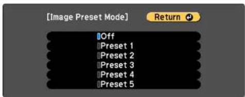
text_image
[Image Preset Mode] Off Preset 1 Preset 2 Preset 3 Preset 4 Preset 5 ReturnEsc / [●]: Return ◆: Select Menu: Exit
Adjusting the Projected Images


- After selecting Preset 1 to Preset 5, you can fine tune each setting individually. The setting after adjustment will be overwritten.
•The setting after adjustment will be overwritten separately when 4K Enhancement is enabled and disabled.

Press the Esc button to return to the previous screen.
Frame Interpolation
The current and previous frames are used to create intermediate frames, interpolating to produce smooth-moving images. You can resolve clumsy-moving images, such as frame skipping when projecting a fast moving image.
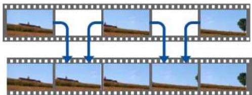
flowchart
graph TD
    A["Top Filmstrip"] --> B["Step 1"]
    B --> C["Step 2"]
    C --> D["Step 3"]
    D --> E["Step 4"]
    E --> F["Final Output"]

You cannot set Frame Interpolation in the following situations.
- When 4K Enhancement is enabled
- When a signal with a resolution that exceeds WUXGA is input
- When Aspect is set to V-Zoom
- When Scale is set to Auto or Manual
- When Edge Blending is set to On

Select Frame Interpolation from Image Enhancement, and then press the [√] button.

Select the level of interpolation from Low, Normal or High. Set to Off if noise occurs after setting them.

text_image
[Frame Interpolation] Return Off Low Normal High [Esc] / [◆]:Return [◆]:Select [Menu]:Exit
Press the Menu button to finish making settings.
Noise Reduction
You can smooth out rough images for softer image quality when inputting progressive signals or progressive interlace signals.

This is disabled in the following cases.
- When 4K Enhancement is enabled
- When a signal with a resolution that exceeds WUXGA is input
1 Select Noise Reduction from Image Enhancement, and then press the [J] button.
2 Use the [◀][▶] buttons to adjust the value.

text_image
[Image Enhancement] Noise Reduction 0 Return [Esc] / [O]:Return [◆]:Select [Menu]:Exit3 Press the Esc button to return to the previous screen.
MPEG Noise Reduction
You can reduce dot and block noise that occurs in outlines when projecting MPEG movies.

This is disabled in the following cases.
- When 4K Enhancement is enabled
- When a signal with a resolution that exceeds WUXGA is input
1 Select MPEG Noise Reduction from Image Enhancement, and then press the ↻ button.
2 Select a level to reduce noise from Low, Normal, or High, and then press the ↻ button.
If Off is selected, MPEG Noise Reduction is disabled.

text_image
[MPEG Noise Reduction] Return Off Low Normal High [Esc] / [●]:Return [◆]:Select [Menu]:Exit3 Press the Esc button to return to the previous screen.
Super-resolution
To display a crisp image, you can reduce the blurring that is created on the edge when the resolution of the image signal is scaled up and projected.
1 Select Super-resolution from Image Enhancement, and then press the [√] button.
2 Use the [▲][▼] buttons to select the item, and then use the [◀][▶] buttons to make the adjustments.
Fine Line Adjust: If this parameter is set to a positive value, details such as hair or fabric patterns will be enhanced.
Soft Focus Detail: If this parameter is set to a positive value, the outline, background, and the other main parts of the objects in the image will be enhanced to show them clearly.
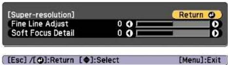
text_image
[Super-resolution] Fine Line Adjust 0 Soft Focus Detail 0 Return [Esc] / [◆]: Return [◆]: Select [Menu]: Exit3 Press the Esc button to return to the previous screen.
Detail Enhancement
You can enhance the contrast in detailed areas of an image to create a more emphatic texture and material feel.
1 Select Detail Enhancement from Image Enhancement, and then press the 🔊 button.
2 Use the [▲][▼] buttons to select the item, and then use the [◀][▶] buttons to make the adjustments.
Strength: The larger the value, the more the contrast is enhanced. Range: The larger the value, the wider the range of detail enhancement becomes.
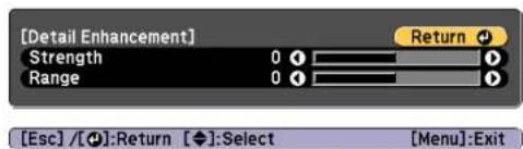
text_image
[Detail Enhancement] Strength 0 Return Range 0 [Esc] / [●]:Return [◆]:Select [Menu]:Exit
text_image
Depending on the image, a highlight may be noticeable at the border between colors. If this bothers you, set a smaller value.3 Press the Esc button to return to the previous screen.
Projecting 3D Images
By using two projectors, you can project passive 3D images. The following are required to project and view 3D images.
•Polarizer
•Passive 3D glasses
- Mount for stacking
Adjusting the Projected Images

•Silver screen for passive 3D

This projector arranges the direction of polarizing projection for R (red), G (green), and B (blue). It is not necessary to inverse left and right eye G (green) image signals.

Useful Functions
This section describes the Multi-Projection, Split Screen, Memory, Schedule, and Security functions.
Multi-Projection Function

You can setup up to 9 projectors to project one large and wide image. You can adjust the difference of brightness and color tone between each projected image to create a seamless screen.

- Set 4K Enhancement to Off. (EB-L1075U/EB-L1070U/EB-L1065U/EB-L1060U/EB-L1050U only)
- We recommend setting the focus, zoom, and lens shift at least 20 minutes after you start the projection, because images are not stable right after turning on the projector.
- If the values for Geometry Correction are large, the image position adjustment for overlapping images becomes difficult.
•The Test Pattern can be displayed to adjust the projection status without connecting video equipment.
"Displaying the Test Pattern" p.33
- If you project a dot by dot image that can be projected without being enlarged or reduced, you can make adjustments precisely.
- When Run Periodically is set to On in Light Source Calibration, calibration is automatically performed, and colors adjusted using multi-projection may change. Set this to Off to maintain the projected image as it is.
Reset - Light Source Calibration - Run Periodically p.162
Adjustment Procedure
Advance preparation
(1) Turn on all projectors.
(2) Set an ID for all projectors and the remote controls.
"Set the projector ID" p.42
Adjusting the projected position
(1) Adjust the position (angle) of the projector.
"Installation Settings" p.31
(2) Adjust the arrangement of the images.
"Tiling" p.90
Adjusting the projected images
(1) Adjust the aspect ratio of the images.
"Screen Settings" p.32
"Changing the Aspect Ratio of the Projected Image" p.80
(2) Adjust the lens shift.
"Adjusting the Position of the Projected Image (Lens Shift Adjustment)" p.34
(3) Adjust the zoom and focus.
"Adjusting the Image Size" p.37
"Correcting the Focus" p.38
(4) Adjust small differences in the images.
"Point Correction" p.74
(5) Adjust the edges of the images.
"Edge Blending" p.91
"Black Level" p.93
(6) Adjust the brightness and tint of the images.
"Color Matching" p.96
(7) Select the sections of the images.
"Displaying a Scaled Image" p.97
Tiling
When using multiple projectors to create one large image, assign a projection position to each projector.

flowchart
graph TD
    A["Input Device"] --> B["Cloud Processing"]
    B --> C["Output Device 1"]
    B --> D["Output Device 2"]
    B --> E["Output Device 3"]
    B --> F["Output Device 4"]

Before performing tiling, adjust the projected image so that it is a rectangle. Also, adjust the size and focus of the images.
"Adjusting the Image Size" p.37
"Correcting the Focus" p.38
1 Press the Menu button while projecting.
2 Select Multi-Projection from Extended, and then press the [◀] button.
3 Select Tiling, and then press the [←] button.
4 Select Layout, and then press the [←] button.
(1) Set the number of projectors in Row and Column.
(2) Select Settings, and then press the [←] button.
5 Repeat steps 1 to 4 for each projector to be used for tiling.
6 Select Location Setup, and then press the [←] button.
(1) Set the positions of the projected images in Row Order and Column Order.
Row Order: Place screens from top to bottom in the order of 1, 2, 3.
Column Order: Place screens from left to right in the order of A, B, C.
| 1A | 1B |
| 2A | 2B |
(2) Select Settings, and then press the [←] button.
7 Repeat step 6 for each projector.
8 Input the image signal to display the image.
"Automatically Detecting Input Signals and Changing the Projected Image (Source Search)" p.61
When tiling is complete, adjust any positional gaps and the tint of the projected images.
"Adjusting the projected images" p.90
Edge Blending
You can fine tune the overlapping areas to make seamless screen.

natural_image
Two rectangular panels: one gradient gray, the other with a dashed rectangle (no text or symbols)
Before performing edge blending to raise the precision of adjustments, press the [Color Mode] button on the remote control, and then Color Mode to Multi-Projection.
set
1 Press the Menu button while projecting.
2 Select Multi-Projection from Extended.
3 Select Edge Blending, and then press the [←] button.
The following screen is displayed.

text_image
[Edge Blending] Return Edge Blending Off Top Edge Off Bottom Edge Off Left Edge Off Right Edge Off Line Guide Off Pattern Guide Off Guide Color Red [Esc] / [◆]:Return [◆]:Select [Menu]:Exit| Submenu Function | |
| Edge Blending | Set to On to activate Edge Blending. Set to Off when not projecting from multiple projectors. |
| Submenu Function | |
| Top Edge/Bottom Edge/Left Edge/Right Edge | Blending: Set to On to activate Edge Blending towards your settings, and the blend range will be shaded.Blend Start Position: Displays blending start position as a red line, and adjusts at the level of one pixel.Blend Range: Adjusts the range to be shaded. Adjustment is possible at the level of one pixel. The maximum range is 45% of the resolution.Blend Curve: Select how to apply shading. |
| Line Guide | Set to On to display a guide on the Edge Blending setting range. |
| Pattern Guide | Set to On to display a lattice pattern to match the position of the Edge Blending setting range. |
| Guide Color | Select a combination of guide colors. |
5 Set Line Guide to On.
(1) Select Line Guide, and then press the [←] button.
(2) Select On, and then press the [←] button.
(3) Press the Esc button.

If the guide is not clear, you can change the color of the guide in Guide Color.
6 Set Pattern Guide to On.
(1) Select Pattern Guide, and then press the [←] button.
(2) Select On, and then press the [←] button.
(3) Press the Esc button.
7 Set Top Edge, Bottom Edge, Left Edge, or Right Edge according to the parts of the image that are overlapped.
The following shows how to set screen (1) as an example.

text_image
① ③ ②In the example above, you need to adjust the Left Edge because you can see the overlapping areas on the left side of the image (1).
(1) Select Left Edge, and then press the [←] button.
(2) Select Blending, and then press the [←] button.
(3) Select On, and then press the [←] button.
(4) Press the Esc button.
(5) In Blend Start Position, align the blending start position with the edge (2) of the image.
(6) Press the Esc button.
(7) In Blend Range, adjust the range (3) to be shaded. The value for when the overlapped range and the guide are in the same position is the best.
(8) In Blend Curve, adjust how to apply shading.
(9) Press the Esc button.
8 After the settings are complete, set Line Guide and Pattern Guide to Off to finish.
Black Level
When a black image is displayed, only areas where the images overlap stands out. The black level function allows you to match the brightness and tone for areas where the images do not overlap with areas where the images overlap, to make the difference less noticeable.
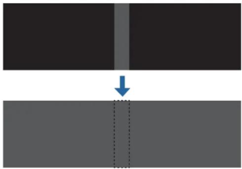
natural_image
Diagram showing a vertical arrow pointing to a dashed rectangular shape, with two dark rectangular blocks above and one gray block below (no text or symbols)
- You cannot adjust the Black Level when a test pattern is displayed.
- If the Geometry Correction value is large, you may not be able to adjust correctly.
- The brightness and tone may differ in areas where the images overlap as well as in other areas even after performing black level adjustment.
- If you change the Top Edge/Bottom Edge/Right Edge/Left Edge setting, the Black Level is returned to its default value. "Edge Blending" p.91
1 Select Black Level from Multi-Projection, and then press the [↓] button.
text_image
Image Signal Settings Extended Network Info Reset [Multi-Projection] Return Projector ID Off Tiling Geometry Correction H/V-Keystone Edge Blending Black Level Scale Photo Color Mode Brightness Settings Color Matching Color Uniformity Reset [Esc]:Return [◆]:Select [●]:Enter [Menu]:Exit2 Select Color Adjustment, and then press the [←] button.
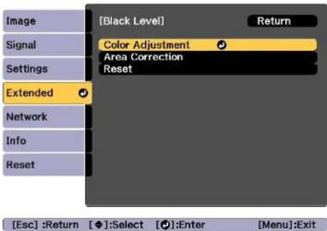
text_image
[Black Level] Return Signal Color Adjustment Area Correction Reset Settings Extended Network Info Reset [Esc] :Return [◆]:Select [●]:Enter [Menu]:ExitThe areas are displayed based on the settings for Top Edge/Bottom Edge/Right Edge/Left Edge.
3 Select the area you want to adjust, and then press the [] button.
The selected area is displayed in orange.

text_image
When multiple screens are overlapping, adjust based on the area with the most overlap (the brightest area). In the illustration below, first align (2) with (1), and then adjust so that (3) aligns with (2). ① ② ② ③4 Adjust the black tone and brightness.
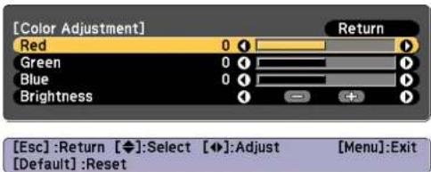
text_image
[Color Adjustment] Red 0 Green 0 Blue 0 Brightness Return [Esc]:Return [◆]:Select [◆]:Adjust [Menu]:Exit [Default]:Reset5 Repeat steps 3 and 4 as needed to adjust any remaining parts.

After this, if the tone for some areas do not match, adjust them by Area Correction.
6 Press the Esc button, to return to the screen displayed in step 2.
7 Select Area Correction, and then press the [←] button.

text_image
[Black Level] Return Color Adjustment Area Correction Reset Settings Extended Network Info Reset [Esc] :Return [◆]:Select [●]:Enter [Menu]:Exit8 Select Start Adjustments, and then press the [←] button.

text_image
[Area Correction] Return Start Adjustments Points 0 Settings Extended Network Info Reset [Esc] :Return [◆]:Select [●]:Enter [Menu]:ExitBoundary lines that indicate areas where images overlap are displayed.
The boundary lines are displayed based on the settings for Top Edge/Bottom Edge/Right Edge/Left Edge.
9 Use the [▲][▼][◀][▶] buttons to select a boundary line of the area you want to adjust.
The selected line is displayed in orange.

natural_image
Simple geometric shape: a black triangle on a gray background with a vertical line and horizontal line (no text or symbols)10 Press the ↓ button to confirm the selection.

11 Use the [▲][▼][◀][▶] buttons to adjust the boundary line positions, and then press the [↓] button.
12 Press the [▲][▼][◀][▶] buttons to select the point you want to move, and then press the◀[ ] button. The selected point is displayed in orange.

13 Press the [▲][▼][◀][▶] buttons to move the point. To continue to move another point, press the |Esc| button to return to step 12, and then repeat steps 12 and 13. To adjust another boundary line, press the Esc button until the screen for selecting a boundary line from step 9 is displayed.

To return Black Level to its default value, press the Esc button to return to the screen from step 7, select [Reset], and then press the ↓ button.
14 To complete the adjustment, press the Menu button.
Color Matching
You can fine tune the color balance and brightness from black to white for each color tone.
1 Select Color Matching from Multi-Projection, and then press the [◀] button.
The following screen is displayed.
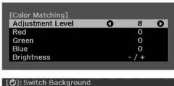
text_image
[Color Matching] Adjustment Level 8 Red 0 Green 0 Blue 0 Brightness - / +Half of the overlapped area is displayed in black so that it is easy to check the edge of the image.

Adjustment Level: There are eight levels from white, through gray, and up to black. You can adjust each level individually. Red, Green, Blue: Adjusts the tone for each color. Brightness: Adjusts the image brightness.

Whenever the 🎨 button is pressed, the screen changes between the projected image and the adjustment screen.
2 Select Adjustment Level, and then use the [◀][▶] buttons to set the adjustment level.
3 Select Red, Green, or Blue, and then press the [◀][▶] buttons to adjust the color tone.
4 Select Brightness, and then use the [◀][▶] buttons to adjust the brightness.
5 Return to step 1 and adjust each level.
6 Press the Esc button to return to the previous screen.
Displaying a Scaled Image
A section of the image is cropped and displayed. This allows you to create one large image by combining images projected from multiple projectors.
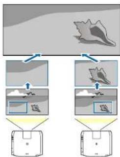
flowchart
graph TD
    A["Input"] --> B["Process 1"]
    A --> C["Process 2"]
    B --> D["Output 1"]
    C --> E["Output 2"]
1 Project the image, and then press the Menu button.
2 Select Multi-Projection from Extended.

You can also perform the same operation from Scale in Signal.
3 Select Scale, and then press the [←] button.
4 Turn on Scale.
(1) Select Scale, and then press the [←] button.
(2) Select Auto or Manual, and then press the [←] button.
Auto: Automatically adjusts the clipped area according to the adjustment values in Edge Blending and Tiling. You do not need to perform any steps after step 6.
Manual: Allows you to adjust the clipped area manually.
(3) Press the Esc button to return to the previous screen.

If auto adjustment does not work for the clipped image, adjust the aspect ratio, and then select Auto.
"Changing the Aspect Ratio of the Projected Image" p.80
5 Set Scale Mode.
(1) Select Scale Mode, and then press the [←] button.
(2) Select Zoom Display or Full Display, and then press the [←] button. Zoom Display: Adjusts according to the image currently displayed.
Enlarge

natural_image
Two-panel image showing a beach scene before and after transformation, with no visible text or symbols.Move

natural_image
Diagram showing a fish jumping from water surface to dark environment, with no visible text or symbolsFull Display: Adjusts according to the projector's panel size (the maximum area in which an image can be displayed).
Enlarge

natural_image
Two-step diagram showing a person standing on water with cloud-like patterns, before and after transformation (no text or symbols)Move

natural_image
Diagram showing a person floating on water with cloud-like patterns, transforming into a dark rectangular frame (no text or symbols)(3) Press the Esc button to return to the previous screen.
6 Adjust the scale.
Select the adjustment method with the [▲][▼]buttons, then adjust using the [■][▶] buttons. (Minimum magnification of 0.5 to maximum magnification of 10)
-+: Enlarges or reduces an image horizontally and vertically at the same time.
Scale Vertically: Enlarges or reduces an image vertically.
Scale Horizontally: Enlarges or reduces an image horizontally.
7 The image is clipped and adjusted.
(1) Select Clip Adjustment, and then press the [◀] button. If you select Clip Range, the range and coordinates of the image that the projector will project is displayed.
(2) Use the [▲], [▼], and [ ] buttons to scroll the image. Adjust the coordinates and size of each image while viewing the screen.
(3) Press the Menu button to finish making settings.

You can check the displayed area after clipping for the entire image from Clip Range.
Projecting Two Images Simultaneously (Split Screen)
You can simultaneously project images from two sources on the right and left of the screen.

bar_line
| Month | Bar Value | Line Value | |---|---|---| | Jan | 10 | 8 | | Feb | 6 | 9 | | Mar | 5 | 7 | | Apr | 7 | 8 | | May | 6 | 7 | | Jun | 4 | 6 | | Jul | 5 | 7 | | Aug | 6 | 8 | | Sep | 5 | 7 | | Oct | 4 | 6 | | Nov | 6 | 7 | | Dec | 7 | 8 |
You cannot use the Split Screen feature in Content Playback mode.
Input Sources for Split Screen Projection
The combinations of input sources that can be projected on a split screen are listed below.
| Left Screen Right Screen | ||||||
| HDMI HDBa-seT | DVI-D Com-puter | BNC LAN | ||||
| HDMI - | √ | √ | √ | √ | √ | |
| HDBaseT - | √ | √ | √ | √ | √ | |
| DVI-D - | √ | √ | √ | √ | √ | |
| Computer - | √ | √ | √ | |||
| BNC | √ | √ | √ | - | - | - |
| LAN | √ | √ | √ | - | - | - |

- Signals with a horizontal resolution that exceeds 1920 are not supported.
- If 4K Enhancement is enabled, a message is displayed. Select Yes to disable 4K Enhancement. (EB-L1075U/EB-L1070U/EB-L1065U/EB-L1060U/EB-L1050U only)
Image - Image Enhancement - 4K Enhancement p.140
Operating procedures
Projecting on a split screen
1 Press the [Split] button on the remote control while projecting. The currently selected input source is projected on the left of the screen.


You can perform the same operations from the configuration menu.
Settings - Split Screen p.143
2 Press the Menu button.
The Split Screen Setup screen is displayed.

text_image
[Split Screen Setup] Screen Size Equal Source Swap Screens Audio Source Auto [Network] Display the QR Code Exit Split Screen
Select
3 Select Source, and then press the [←] button.
4 Select each input source for Left and Right.

text_image
[Source] Return Left Right HDMI HDBaseT DVI-D Computer BNC LAN Execute
/ [+] : Return

You can perform the same operations using the following procedure.
"Automatically Detecting Input Signals and Changing the Projected Image (Source Search)" p.61
"Switching to the Target Image by Remote Control" p.62
5 Select Execute, and then press the [←] button.
To switch the source during split screen projection, start the procedure from step 2.
Projection Functions

101
Switching the left and right screens
Use the following procedure to switch the projected images.
1 Press the Menu button during split screen projection.
2 Select Swap Screens, and then press the [◀] button. The projected images on the left and right are swapped.
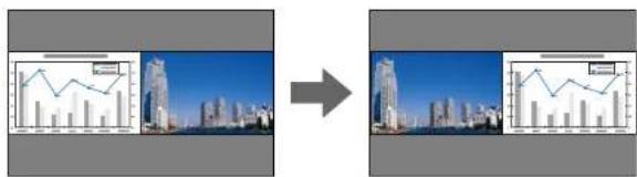
text_image
Comparison image showing two cityscape photos with overlaid line graphs and a magnified inset graph, likely from a photo processing or analysis workflow.Switching the left and right image sizes
1 Press the Menu button during split screen projection.
2 Select the Screen Size, and then press the [←] button.
3 Select the screen size you want to display, and then press the []← button.

text_image
[Screen Size] Return Equal Larger Left Larger RightEsc:Return ◆:Select [●]:Set Menu:Exit
The projected images will appear as shown below after setting the screen size.
Equal Larger Left

line
| Date | Value | |---|---| | 2018-01-01 | 1.0 | | 2018-02-01 | 1.5 | | 2018-03-01 | 2.0 | | 2018-04-01 | 1.8 | | 2018-05-01 | 2.5 | | 2018-06-01 | 2.2 | | 2018-07-01 | 2.8 | | 2018-08-01 | 3.0 | | 2018-09-01 | 2.7 | | 2018-10-01 | 3.5 | | 2018-11-01 | 3.2 | | 2018-12-01 | 3.8 |
bar_line
| Period | Bar Value | Line Value | |---|---|---| | 1 | 0.8 | 0.9 | | 2 | 0.6 | 0.7 | | 3 | 0.7 | 0.8 | | 4 | 0.6 | 0.6 | | 5 | 0.7 | 0.7 | | 6 | 0.8 | 0.6 | | 7 | 0.9 | 0.5 | | 8 | 0.8 | 0.6 | | 9 | 0.9 | 0.7 |Larger Right
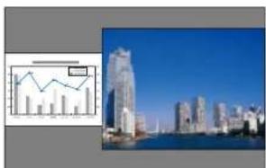
text_image
Composite image showing a line chart and city skyline with skyscrapers, alongside a small inset bar chart.
- You cannot enlarge both the left screen and right screen images at the same time.
- When one image is enlarged, the other image is reduced.
- Depending on the video signals that are input, the images on the left and right may not appear to be the same size even if Equal is set.
Changing the audio
1 Press the Menu button during split screen projection.
2 Select Audio Source, and then press the [◀] button.
Projection Functions

102
3 Select the audio you want to output, and then press the [] button.
When you select Auto, audio is output for the enlarged screen. If the screen sizes are Equal, audio is output for the screen on the left.

text_image
[Audio Source] Return Auto Screen Left Screen Right [Esc] / [O]:Return [◆]:Select [Menu]:ExitEnding the split screen
Press the [Esc] button to end split screen.
The following steps can also be used to end the split screen.
- Press the [Split] button on the remote control.
- Select Exit Split Screen on the Split Screen Setup screen. p.100
Restrictions during split screen projection
Operating restrictions
The following operations cannot be performed during split screen projection.
- Setting the configuration menu
•E-Zoom
•Changing the aspect mode - Using the [User1], [User2], or [User3] button on the remote control
- Help can be displayed only when image signals are not input or when an error or warning notification is displayed.
•The user's logo is not displayed.
Restriction relating to images
- For the image on the right screen, the default values for the Image menu are applied. However, the settings for the image projected on the left screen are applied to the image on the right screen for Color Mode, Color Temp., Frame Interpolation, and Super-resolution.
- Deinterlacing and Noise Reduction are only enabled for the left screen.
Hiding the Image and Sound Temporarily (A/V Mute)
You can use this when you want to focus the audience's attention on what you are saying, or if you do not want to show details such as when you are changing between files during presentations from a computer.

flowchart
graph TD
    A["Input Box"] --> B["Bar Chart 1"]
    B --> C["Bar Chart 2"]
    C --> D["Output Table"]
    D --> E["Next Step"]
    E --> F["Blank Output"]
Each time you press the [A/V Mute] button, A/V Mute turns on or off.
Remote control
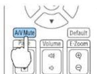

- When A/V Mute is enabled, the light source turns off.
- If you want to fade out or fade in when turning the video on or off, set the desired number of seconds in Fade-out and Fadc-in.
Extended - Operation - A/V Mute Settings - Fade-out, Fade-in p.146
- When A/V mute is activated and no operations are performed for about 2 hours, the projector turns off automatically. If you do not want to turn off the power, set A/V Mute 'Timer to Off.
Extended - Operation - A/V Mute Settings - A/V Mute Timer p.146
- When A/V Mute Release is set to A/V Mute from the configuration menu, the following operations can still be performed without releasing A/V mute.
- Change the source with the change input buttons on the remote control.
- Control the projector from a computer using communication commands.
Extended - Operation - A/V Mute Settings - A/V Mute Release p.146
A/V mute is only released by pressing the [A/V Mute] button, or by sending an A/V mute Off command.
- When projecting moving images, the images and sound continue to be played back while A/V Mute is on. It is not possible to resume projection from the point where A/V Mute was activated.
Freezing the Image (Freeze)
When Freeze is activated on moving images, the frozen image continues to project on the screen, so you can project a moving image one frame at a time like a still photo. Also, you can perform operations such as changing between files during presentations from a computer without projecting any images if the Freeze function is activated beforehand.
Each time you press the |Freeze| button, Freeze turns on or off.
Remote control


•Audio does not stop.
- When projecting moving images, the images continue to be played back while the screen is frozen. It is not possible to resume projection from the point where the screen was frozen.
- If the [Freeze] button is pressed while the Configuration menu or the Help screen is displayed, the menu or the Help screen that is displayed is closed.
- Freeze still works while E-Zoom is being used.
Enlarging Part of the Image (E-Zoom)
This is useful when you want to expand images to see them in greater detail, such as graphs and tables.

bar_line
| Category | Bar Value | Line Value | | -------- | --------- | ---------- | | Top Left | 100 | 100 | | Top Right| 80 | 90 | | Bottom Left| 60 | 70 | | Bottom Right| 50 | 60 | | Bottom Left| 40 | 50 | | Bottom Right| 30 | 40 | | Bottom Left| 20 | 30 | | Bottom Right| 10 | 20 | | Bottom Left| 5 | 10 | | Bottom Right| 0 | 5 |1 Start E-Zoom.
Press the Ⓔ] button to display the Cross

2 Move the Cross ( ) to the area of the image that you want to enlarge.


3 Enlarge.
Remote control

[④] button: Expands the area each time it is pressed. You can expand quickly by holding the button down.
|⊖| button: Reduces images that have been enlarged.
Esc button: Cancels E-Zoom.

- During enlarged projection, press the [▲], [▼], [◀], or [▶] buttons to scroll the image.
- E-Zoom is unavailable when Scale is on. Signal - Scale p.142
- If 4K Enhancement is enabled, a message is displayed. Select Yes to disable 4K Enhancement. (EB-L1075U/EB-L1070U/EB-L1065U/FB-L1060U/FB-L1050U only)
Image - Image Enhancement - 4K Enhancement p.140
Saving a User's Logo
You can save the image that is currently being projected as a User's Logo.

- When User's Logo Protection from Password Protection is set to On, a message is displayed and the User's Logo cannot be changed. Perform operations after setting User's Logo Protection to Off.
"Managing Users (Password Protection)" p.115
- If you use the batch setup function to copy menu settings between multiple projectors, the User's Logo is also copied. Do not set images that you do not want to share across multiple projectors as the User's Logo.
1 Project the image you want to save as the User's Logo, and then press the Menu button.
"Configuration Menu Operations" p.136
2 Select User's Logo from Extended.

When you select User's Logo, settings such as Geometry Correction, E-Zoom, Aspect, Scale, and Screen Type are temporarily disabled.
3 Select Start Setting, and then press the [←] button.
The confirmation screen is displayed.
4 Select Yes, and then press the [←] button.
When the message "Save this image as the User's Logo?" is displayed, select Yes.
The image is saved. After the image has been saved, the message "Completed." is displayed.

Select Reset to delete the image you registered and return to the default settings.
Content Playback Feature

Content Playback mode allows you to project images suitable for digital signage in locations such as museums, showrooms, and stores. You can project playlists of photos and videos stored in an external memory. You can use the effects features to change the color and shape of the projected image.

natural_image
Interior view of a gallery hallway with two people viewing a framed floral artwork on the wall (no text or symbols visible)
The Content Playback feature uses the USB-A port; this means that you cannot use the wireless LAN feature at the same time.
Switching to Content Playback Mode
Switch to Content Playback mode to play a playlist.
1 Press the Menu button while projecting.
2 Select Content Playback from Settings.
3 Select On, and then press the [←] button. A confirmation message is displayed.
4 Restart the projector to enable Content Playback mode.
5 Press the [button on the control panel or the remote control. The Home screen is displayed.
6 Check that Content Playback mode is enabled.

text_image
EPSON Sources : Switching at sources... HDME HDBaseT DVI-0 Computer BNC USB LAN Userful functions Color Mode Light Source Mode Image Enhancement Frame Interpolation Menu Help Constant Playback : On Projector Value: XXXXXXXX Keyword: XXXXX $50 : XXXXXXXX-XXXXXXXXXX IP : XXXXXXXX IP : XXXXXXXX.XXX Connective Guide Switch the source. Close) ExitPlaying a Playlist
Content Playback mode allows you to project photos and videos that have been saved as playlists.

flowchart
graph LR
    A["Laptop with icons"] --> B["USB"]
    B --> C["Monitor displaying a PNG file with 'Playoff 1', 'Playoff 2', 'Playoff 3', 'Playoff 4', 'Playoff 5', 'Playoff 6', 'Playoff 7', 'Playoff 8'"]

-
You need to assign USB to a User Button in advance. Settings - User Button p.143
•The USB flash drive must meet the following requirements. -
Formatted as FAT 16/32
- Only one partition
- No security features enabled
- Do not use a multi-card reader or USB hub
- Total length of USB flash drive is 6 cm or less
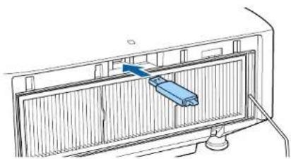
natural_image
Diagram of a device inside a rack with a blue component inserted, showing no text or symbols
Press the user button assigned to USB on the remote control. The first playlist or the scheduled playlist is played.

- Press the numeric buttons while holding down the [Num] button to play a playlist that has been registered to you favorites. You can register favorites using Epson Projector Content Manager.
- To select a playlist to play from the list, select USB Viewer from the Settings menu, and then use the up, down, left, and right buttons to select your file.
Settings - Content Playback - USB Viewer p.143
1 Create a playlist using Epson Projector Content Manager and save it to a USB flash device.

See the "Epson Projector Content Manager Operation Guide" for details.
2 Connect the USB flash drive to the projector's USB-A port (the wireless LAN module installation section) while Content Playback mode is enabled.
"Installing the Wireless LAN Unit" p.54
Adding Effects to Images (Effect Feature)
In Content Playback mode, you can change the color and shape of the image you are projecting.

natural_image
Two circular images showing a floral arrangement with pink roses and white flowers, no text or symbols visible.
When using the Effect feature, you need to run Refresh Mode periodically.
Reset - Refresh Mode p.162
1 Press the Menu button while Content Playback mode is enabled, select [Settings], and then press the◀] button.
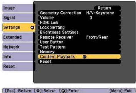
text_image
Image Signal Settings Extended Network Info Reset Geometry Correction H/V-Keystone Volume 0 HDMI Link Lock Setting Brightness Settings Remote Receiver Front/Rear User Button Test Pattern Memory Content Playback Reset [Esc] .Return [◆].Select [●].Enter [Menu].Exit2 Select Overlay Effect from Content Playback, and then press the [◀] button.
3 Set Overlay Effect to On, and then press the [←] button.

text_image
[Overlay Effect] Overlay Effect Off Shape Filter Off Color Filter Off Lightness 0 [◆]:Select [◆]:Enter [Menu]:Exit4 Select Shape Filter, and then press the [◀] button.
5 Adjust the following items as necessary.
- Shape: Select the shape of the effect from Circle, Square, or Custom.

You can register your favorite images to Custom using Epson Projector Content Manager. See the "Epson Projector Content Manager Operation Guide" for details.
- Filter Effect: Select whether to mask the inside or the outside of the selected shape.
•Size: Set the size of the selected shape. - Position: Set the display position of the selected shape.
6 Select Color Filter, and then press the [←] button.
7 Adjust the following items as necessary.
•Color Filter: Select the color of the effect.
- Custom: Adjust the Red, Green, and Blue.
8 Select Lightness to set the brightness of the effect.
9 Press the Menu button to finish making settings.
Restrictions on Content Playback Mode
Operating restrictions
You cannot change the following operations or settings in Content Playback mode.
Content Playback Feature

• Color Temp. (when Warm White or Cool White is selected as the Color Filter)
- Blanking
- Split Screen
- Display Background
•Screen
•Auto Source Search
- Remote Password
-Edge Blending
- Log Save Destination
Also, you cannot use Epson Projector Professional Tool in Content Playback mode.
Memory Function

The settings for the image currently displayed and values for geometry correction are saved as a memory, allowing you to load them when necessary.
Saving/Loading/Erasing/Resetting the Memory
1 Press the [Memory] button while projecting.
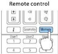

You can also operate from the Configuration menu.
Settings - Memory p.143
2 Select a memory type, and then press the [] button.

text_image
[Memory] Return Settings Memory Lens Position Geometry Correction Extended Network Info Reset [Esc] /[●]:Return [◆]:Select [Menu]:ExitMemory: Settings for the following menu items are saved in the memory. You can register up to 10 values.
| Top Menu Submenu | |
| Image | All setting items |
| Signal | Scale |
| Settings | Brightness Settings |
| Extended | Edge BlendingBlack LevelColor Matching |
Lens Position: Registers the position of the lens adjusted using lens shift, zoom, focus, and distortion. You can register up to 10 values. "Registering and Loading Lens Adjustment Values" p.39
Geometry Correction: Adjustment value of the geometry correction is saved. You can register up to 3 values.
3 Select the function you want to perform, then press the [] button.

text_image
[Memory] Return Load Memory Save Memory Erase Memory Rename Memory Reset Memory Settings Extended Network Info Reset [Esc] / [●]: Return [◆]: Select [Menu]: Exit| Function Explanation | |
| Load Memory | Loads the saved memory. When you select a memory and press the [←] button, the settings applied to the current image are replaced with the settings from the memory. |
| Save Memory | Registers current settings in the memory. When you select a memory name and press the [←] button, the settings are saved. |
| Erase Memory | Erases the registered memory. When you select a memory name and press the [←] button, a message is displayed. Select Yes, and then press the [←] button to erase the selected memory. |
| Rename Memory | Changes the memory name. Select the memory name you want to change, and then press the [←] button. Enter the memory name using the soft keyboard. "Soft keyboard operations" p.152When you have finished, move the cursor over Finish, and then press the [←] button. |
| Function Explanation | |
| Reset Memory | Resets the name and settings of a saved memory.To reset all memories saved in Memory, Lcns Position, and Geometry Correction, use Reset All Memories.◆ Reset - Reset All Memories p.162 |

If the mark on the left of the memory name is turned blue, it means the memory has already been registered. When you select a registered memory, a message is displayed asking you to confirm that you want to overwrite the memory. If you select Yes, the previous settings are deleted and the current settings are registered.
Scheduling Function

You can schedule turning the projector power on/off and switching the input source, as events in the schedule. Registered events are executed automatically at the specified time on the specified dates or weekly. You can register up to 30 events in Schedule, and one event in Extended Schedule.
Saving an Event
Setting an Event
1 Press the Menu button while projecting. "Configuration Menu Operations" p.136
2 Select Schedule Settings from Extended. 3 Select Add New from Schedule.
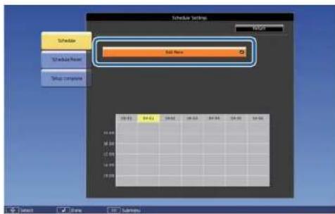
text_image
Schedule Settings Start Now End Now 10:00 24:00 30:00 36:00 42:00 48:00 54:00 60:00 66:00 72:00 78:00 84:00 90:00 96:00 102:00 108:00 114:00 120:00 126:00 132:00 138:00 144:00 150:00 156:00 162:00 168:00 174:00 180:00 186:00 192:00 198:00 204:00 210:00 216:00 222:00 228:00 234:00 240:00 246:00 252:00 258:00 264:00 270:00 276:00 282:00 288:00 294:00 300:00 306:00 312:00 318:00 324:00 330:00 336:00 342:00 348:00 354:00 360:00 366:00 372:00 378:00 384:00 390:00 396:00 402:00 408:00 414:00 420:00 426:00 432:00 438:00 444:00 450:00 456:00 462:00 468:00 474:00 480:00 486:00 492:00 498:00 504:00 510:00 516:00 522:00 528:00 534:00 540:00 546:00 552:00 558:00 564:00 570:00 576:00 582:00 588:00 594: 1 2 3 4 5 6 7 8 9 1 1 1 1 1 1 1 1 1 1 1 1 1 1 1 1 1 1 1 1 1 1 1 1 1 1 1 1 1 1 1 1 1 14 Set the schedule.
| Submenu Name Function | |
| Event Settings | Select an operation of the projector when the event is executed. Select No Change for items that you do not want to change when the event occurs.You can set the following item operations.SchedulePowerSourceLight Source ModeA/V MuteLight Source CalibrationRefresh ModeVolume |
| Date / Time Settings | Set the date, day of the week, and time to execute the event. You can set up to four weeks later. Use the soft keyboard to enter the date and time."Soft keyboard operations" p.152 |
5 Select Save, and then press the [←] button.
To register additional events, repeat steps 3 to 5.
6 Select Setup complete, and then select Yes to finish saving.

- Light Source Calibration does not start automatically when the projector is used continuously for more than 24 hours, or when direct shutdown is used regularly. Set Light Source Calibration to enable this function after every 100 hours of usage. - When Light Source Calibration is enabled, turn on the projector at least 20 minutes before the event.
Scheduling Function

Checking an Event
This section explains how to check a Schedule event.
1 Press the Menu button while projecting.
2 Select Schedule Settings from Extended.
3 Press the [◀][▶] buttons to highlight the date you want to check. The details of the events registered on the selected date are displayed. The indicator turns on when an event is saved.

text_image
Schedule Settings Add Noise 08:00 / Sandy/Communication (0) 13:00P / Power Consumption (DCI) 15:00P / Service (SIC) 17:00P / Power Consumption (Normal) 04:00 04:00 04:00 04:00 04:00 Select Show Latency Latency(Blue): Enabled event
(Gray): Disabled event
: Regular event
(Aqua): Single event
(Orange): Regular event
(Green): Communication monitoring On/Off
= (Gray): Disabled event
Editing an Event
1 Press the Menu button while projecting.
"Configuration Menu Operations" p.136
Scheduling Function

2 Select Schedule Settings from Extended.
3 Use the [◀][▶] buttons to highlight the date containing the event you want to edit.
4 Highlight the event you want to edit, and then press the Esc button.
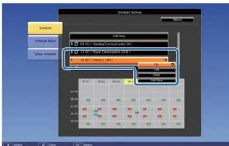
text_image
Schedule Settings Add Time 08:00 / ScanRay/Communication (0) 13:00 / Filter Communication (5) 15:00 / Save (1.0M) 0.0 0.0 0.0 0.0 0.0 0.0 0.0 0.0 0.0 0.0 0.0 0.0 0.0 0.0 0.0 0.0 0.0 0.0 0.0 0.0 0.0 0.0 0.0 0.0 0.0 0.05 Edit the event.
| Submenu Name Function | |
| On/Disabled | Enable or disable the selected event. |
| Edit | Edits the content of the selected event. Select Save, and then press the [←] button to complete the editing. |
| Clear | Deletes the selected event. |
| Add New | Saves a new event. Select Save, and then press the [←] button to complete registering. |
6 Select Setup complete, and then select Yes to finish editing.

text_image
Schedule Settings Back to Configuration Setup menu Show Show Event Setup console Set the schedule settings? Yes Cancel
To delete all registered events, select Schedule Reset, and then select Yes. Select Setup complete, and then select Yes to delete the events.
The projector has the following enhanced security functions.
- Password Protection
You can limit who can use the projector.
•Control Panel Lock/Remote Control Button Lock
You can prevent people changing the settings on the projector without permission.
"Restricting Operation" p.117
•Anti-Theft Lock
The projector is equipped with the following anti-theft security device.
"Anti Theft/Fall Prevention" p.119
Managing Users (Password Protection)
When Password Protection is activated, people who do not know the password cannot use the projector to project images even if the projector power is on. Furthermore, the user's logo that is displayed when you turn on the projector cannot be changed. This acts as an anti-theft function as the projector cannot be used even if it is stolen. At the time of purchase, Password Protection is not activated.
Kinds of Password Protection
The following four kinds of Password Protect settings can be made according to how the projector is being used.
•Power On Protection
When Power On Protection is On, you need to enter a preset password after the projector is plugged in and turned on (this also applies to Direct Power On). If the correct password is not entered, projection does not start.
-User's Logo Protection
Even if someone tries to change the User's Logo set by the owner of the projector, it cannot be changed. When User's Logo Protection is set to On, the following setting changes for the User's Logo are prohibited.
•Capturing a User's Logo
- Setting Display Background or Startup Screen from Display
Extended - Display p.146
•Network Protection
When Network Protection is set to On, changing the settings for Network is prohibited.
"Network Menu" p.151
•Schedule Protection
When Schedule Protection is set to On, changing settings for the projector's system time or schedules is prohibited.
Setting Password Protection
Use the following procedure to set Password Protect.
1 During projection, hold down the [Freeze] button for about five seconds.
The Password Protection setting menu is displayed.
Remote control


If Password Protection is already activated, you must enter the password.
If the password is entered correctly, the Password Protection setting menu is displayed.
"Entering the password" p.116
2 Select the type of Password Protect you want to set, and then press the 📄 button.

text_image
[Password Protection] Power On Protection Off User's Logo Protection Off Network Protection Off Schedule Protection Off Password [◆]:Select [●]:Enter [Menu]:Exit3 Select On, and then press the [←] button.
Press the Esc button to display the screen from step 2.
4 Set the password.
(1) Select Password, and then press the [←] button.
(2) When the message "Change the password?" is displayed, select Yes and then press the [◀] button. The default password is set to "0000". Change this to your own desired password. If you select No, the screen displayed in step 2 is displayed again.
(3) While holding down the [Num] button, enter a four digit number using the numeric buttons. The number entered is displayed as "****". When you enter the fourth digit, the confirmation screen is displayed.

(4) Re-enter the password.
"Password accepted." is displayed.
If you enter the password incorrectly, a message is displayed prompting you to re-enter the password.
Entering the password
When the password entry screen is displayed, enter the password using the remote control.
While holding down the [Num] button, enter the password by pressing the numeric buttons.

text_image
[Password] Enter the password. See your documentation for more information. [0-9] :EnterWhen you enter the correct password, Password Protect is temporarily released.
Attention
- If an incorrect password is entered three times in succession, the message "The projector's operation will be locked." is displayed for approximately five minutes, and then the projector switches to standby mode. If this happens, disconnect the power plug from the electrical outlet and then reinsert it and turn the projector's power back on. The projector displays the password entry screen again so that you can enter the correct password.
- If you have forgotten the password, make a note of the "Request Code: xxxxx" number that appears on the screen and contact the nearest address provided in the Epson Projector Contact List.
Epson Projector Contact List
- If you continue to repeat the above operation and input the wrong password thirty times in succession, the following message is displayed and the projector does not accept any more password entries. "The projector's operation will be locked. Contact your nearest Epson service center."
Epson Projector Contact List
Restricting Operation
The following three kinds of operation restriction functions are available with the projector.
•Control Panel Lock
This is useful at events or shows when you want to deactivate all buttons during projection or at schools when you want to limit button operation.
- Lens Lock
This function deactivates all buttons on the remote control related to the lens operation to prevent improper lens adjustment after it is properly adjusted.
- Remote control button lock
This function deactivates buttons except for main buttons needed for basic remote control operation, to prevent mistakes in operations.
Control Panel Lock
Perform one of the following to lock the operation buttons on the control panel. Even if the control panel is locked, you can still use the remote control as usual.
•Full Lock
All of the buttons on the control panel are locked. You cannot perform any operations from the control panel, including turning the power on or off.
- Partial Lock
All of the buttons on the control panel, except for the button, are locked.
1 Press the ⏻ button on the control panel during projection to display the Control Panel Lock screen.

You can also make settings in Control Panel Lock from the configuration menu.
Settings - Lock Setting - Control Panel Lock p.143
2 Select either Full Lock or Partial Lock according to your purpose.

text_image
[Control Panel Lock] Return Full Lock Partial Lock OffEsc:Return ◆:Select [●]:Set Menu:Exit
3 Select Yes when the confirmation message is displayed.
The control panel buttons are locked according to the setting you chose.

You can release the control panel lock by one of the following two methods.
- Use the remote control to set Control Panel Lock to Off from the configuration menu.
Settings - Lock Setting - Control Panel Lock p.143
- Press and hold down the ↓ button on the control panel for about seven seconds, a message is displayed and the lock is released.
Lens Lock
This function locks the following buttons on the remote control related to the lens operation.

Set the Lens Lock to On in the Configuration menu.
Settings - Lock Setting - Lens Lock p.143
Remote control button lock
This function locks the following buttons on the remote control.

flowchart
graph TD
    A["Auto"] --> B["Aspect"]
    B --> C["Color Mode"]
    D["Jet Pattern"] --> E["Freeze"]
    E --> F["Split"]
    G["Lens Shift"] --> H["Zoom"]
    H --> I["Focus"]
    J["Menu"] --> K["Instortion"]
    K --> L["Esc /"]
    M["A/V Mate"] --> N["Page"]
    N --> O["Volume"]
    O --> P["I-Zoom"]
    Q["Geometry"] --> R["Memory"]
    S["User1"] --> T["User2"]
    U["1"] --> V["2"]
    W["4"] --> X["5"]
    Y["7"] --> Z["8"]
    AA["ID"] --> AB["0"]
    AC["On Off"] --> AD["Home"]
Each time the ⏻ button is pressed for approximately 5 seconds, the remote control button lock turns on or off.

text_image
Remote control 4 5 6 7 8 9 ID 0 Num On Off Home
Even if the remote control button lock is on, the following operations are possible.
- Resetting default for the Remote Receiver setting
●Releasing the remote control button lock
Anti Theft/Fall Prevention
The projector is equipped with the following types of anti-theft security devices.
•Security slot
The security slot is compatible with the Microsaver Security System manufactured by Kensington.
See the following for more details on the Microsaver Security System.
http://www.kensington.com/
•Security cable installation point
A commercially available theft-prevention wire lock can be passed through the installation point to secure the projector to a desk or pillar. See the documentation supplied with the wire lock for locking instructions.
You can also attach a safety wire to secure the projector and the ceiling mount to prevent it from falling.

Using the Projector on a Network
Follow the instructions in these sections to set up your projector for use on a network.
Wired Network Projection

You can send images to your projector through a wired network. To do this, connect the projector to your network, and then set up your projector and computer for network projection.
After connecting and setting up the projector, install Epson iProjection from the EPSON Projector Software CD-ROM (if available) or Web site.
Epson iProjection software sets up your computer for network projection. It also allows you to hold interactive meetings by projecting user's computer screens over a network. See the "Epson iProjection Operation Guide (Windows/Mac)" for instructions.
Selecting Wired Network Settings
Before you can project from computers on your network, you need to select network settings on the projector.

Make sure you already connected the projector to your wired network using the LAN port.
"Connecting a LAN Cable" p.52
1 Press the Menu button on the control panel or remote control.
2 Select the Network menu and press [Enter].
3 Select Network Configuration and press [Enter].
4 Select the Basic menu and press [Enter].
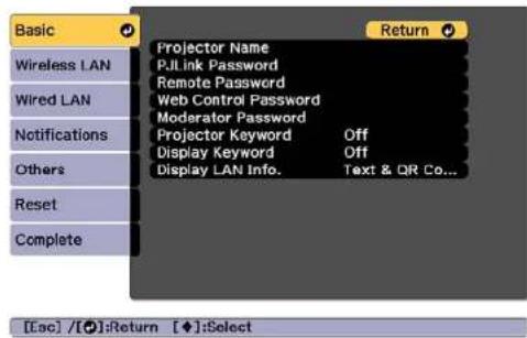
text_image
Basic Wireless LAN Wired LAN Notifications Others Reset Complete Projector Name P.JLink Password Remote Password Web Control Password Moderator Password Projector Keyword Off Display Keyword Off Display LAN Info. Text & QR Co... Return [[sc] /[●]:Return [◆]:Select5 Select the basic options as necessary.
- Projector Name: Enter the projector name used to identify the projector over a network. You can enter up to 16 single-byte alphanumeric characters.
- PJLink Password: Lets you set a password for using the PJLink protocol for projector control. You can enter up to 32 single-byte alphanumeric characters.
- Remote Password: Allows you to set an authentication password for using the Remote function in Epson Web Control when setting or controlling the projector. You can enter up to 8 single-byte alphanumeric characters. (The user name is EPSONREMOTE; the default password is guest.)
- Web Control Password: Allows you to set an authentication password for using Web Control in Epson Web Control when setting or controlling the projector. You can enter up to 8 single-byte alphanumeric characters. (The user name is EPSONWEB; the default password is admin.)
Wired Network Projection

- Moderator Password: Allows you to set an authentication password for using Epson iProjection when connecting to the projector as a moderator. Enter four digits for the password. (There is no default password.)
- Projector Keyword: Lets you turn on a security password to prevent access to the projector by anyone not in the room with it. You must enter a displayed keyword using Epson iProjection to project images and send or receive data.
- Display Keyword: Lets you display a projector keyword on the projection screen when connecting to the projector using Epson iProjection.
- Display LAN Info. lets you set the display format for the projector's network information.

Use the displayed keyboard to enter the name, passwords and keyword. Press [▲][▼][▼] buttons on the remote control to highlight characters and press [Enter] to select them.

Select the Wired LAN menu and press [Enter].
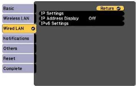
text_image
Basic Wireless LAN Wired LAN Notifications Others Reset Complete IP Settings IP Address Display Off IPv6 Settings ReturnAssign the IP settings for your network as necessary.
- If your network assigns addresses automatically, select IP Settings to set the DHCP setting to On.
- If you must set addresses manually, select IP Settings to set the DHCP setting to Off, and then enter the projector's IP Address, Subnet Mask, and Gateway Address as necessary.
- If you want to connect the projector to the network using IPv6, select IPv6 Settings.
"Wired LAN menu" p.157

Press the [▲][▼][◀][▶] buttons on the remote control, and then select the number you want to enter on the soft keyboard displayed. Press the [Enter] button to confirm.

To prevent the IP address from being displayed on the LAN standby screen and Home screen, set the IP Address Display setting to Off.

If you have finished making settings, select Setup complete. Follow the on-screen instructions to save the settings and close the menu.
Wired Network Projection

10 Press the [LAN] button on the remote control.
The wired network settings complete when you see the correct IP address on the LAN standby screen.
[LAN]
Projector Name :
SSID :
IP Address ↓ :
IP Address (q)
Keyword :
Event ID :
Wireless Network Projection

You can send images to your projector through a wireless network.
To do this, you must install the Epson 802.11b/g/n wireless LAN module, and then set up your projector and computer for wireless projection.
"Installing the Wireless LAN Unit" p.54
You can connect the projector to your wireless network by configuring the connection manually using the projector's Network menus.
Set the projector's time before configuring the Network menu. If the time is not set, the wireless LAN may not be configured correctly.
"Setting the 'Time' p.44
After installing the wireless LAN module and setting up the projector, install the network software from the EPSON Projector Software CD-ROM (if available) or download the software, as necessary. Use the following software and documentation to set up and control wireless projection:
- Epson iProjection (Windows/Mac) software allows you to hold interactive meetings by projecting the computer screens of users over a network. See the "Epson iProjection Operation Guide (Windows/Mac)" for instructions.
- Epson iProjection (iOS/Android) app allows you to project from iOS or Android mobile devices.
You can download Epson iProjection (iOS/Android) for free from App Store or Google Play. Any fees incurred when communicating with the App Store or Google Play are the responsibility of the customer.
- Epson iProjection (Chromebook) allows you to project images from a Chromebook.
You can download Epson iProjection (Chromebook) for free from the Chrome Web Store. Any fees incurred when communicating with the Chrome Web Store are the responsibility of the customer.
Selecting Wireless Network Settings Manually
Before you can project from your wireless network, you need to select network settings for the projector.
1 Press the Menu button on the control panel or remote control.
2 Select the Network menu and press [Enter].

text_image
Image Signal Settings Extended Network Info Reset Return Wireless Mode Wireless LAN... Net. Info. - Wireless LAN Net. Info. - Wired LAN Display the QR Code Network Configuration Wireless LAN Diagnosis [Esc] / [●]: Return [◆]: Select [Menu]: Exit3 Set Wireless Mode to Wireless LAN On.
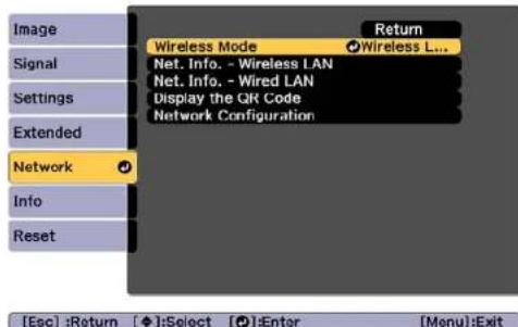
text_image
Image Signal Settings Extended Network Info Reset Return Wireless Mode Wireless L... Net. Info. - Wireless LAN Net. Info. - Wired LAN Display the QR Code Network Configuration [Esc] :Return [◆]:Select [●]:Enter [Menu]:Exit4 Select Network Configuration and press [Enter].
5 Select the Basic menu and press [Enter].
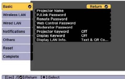
text_image
Basic Wireless LAN Wired LAN Notifications Others Reset Complete Projector Name P&Link Password Remote Password Web Control Password Moderator Password Projector Keyword Off Display Keyword Off Display LAN Info. Text & QR Co... Return [Esc] / [O]:Return [◆]:Select6 Select the basic options as necessary.
- Projector Name: Enter the projector name used to identify the projector over a network. You can enter up to 16 single-byte alphanumeric characters.
- PJLink Password: Lets you set a password for using the PJLink protocol for projector control. You can enter up to 32 single-byte alphanumeric characters.
- Remote Password: Allows you to set an authentication password for using the Remote function in Epson Web Control when setting or controlling the projector. You can enter up to 8 single-byte alphanumeric characters. (The user name is EPSONREMOTE; the default password is guest.)
-
Web Control Password: Allows you to set an authentication password for using Web Control in Epson Web Control when setting or controlling the projector. You can enter up to 8 single-byte alphanumeric characters. (The user name is EPSONWEB; the default password is admin.)
-
Moderator Password: Allows you to set an authentication password for using Epson iProjection when connecting to the projector as a moderator. Enter four digits for the password. (There is no default password.)
- Projector Keyword: Lets you turn on a security password to prevent access to the projector by anyone not in the room with it. Turn on "Projector Keyword" when using thumbnail display or the send function between the projector and connected devices.
- Display Keyword: Lets you display a projector keyword on the projection screen when connecting to the projector using Epson iProjection.
- Display LAN Info. lets you set the display format for the projector's network information.

Use the displayed keyboard to enter the name and password. Press [▲][▼] [▲] buttons on the remote control to highlight characters and press [Enter] to select them.
7 Select the Wireless LAN menu and press [Enter].

text_image
Basic Wireless LAN Wireed LAN Notifications Others Reset Complete Connection Mode Quick SSID Security Open Passphrase Channel 1ch SSID Display Off IP Address Display Off IPv6 Settings Return8 Select the Connection Mode setting.
- Quick lets you connect to multiple smartphones, tablets, or computers directly using wireless communication.
- Advanced: Lets you connect to a smartphone, tablet, or computer over a wireless LAN access point.
9 If you selected the Advanced connection mode, select Search Access Point to select the access point you want to connect to.

If you need to assign the SSID manually, select SSID to enter the SSID.
10 For the Advanced connection mode, assign the IP settings for your network as necessary.
- If your network assigns addresses automatically, select IP Settings to set the DHCP setting to On.
- If you must set addresses manually, select IP Settings to set the DHCP setting to Off, and then enter the projector's IP Address, Subnet Mask, and Gateway Address as necessary.
- If you want to connect the projector to the network using IPv6, select IPv6 Settings.
"Wireless LAN menu" p.154
11 To prevent the SSID or IP address from being displayed on the LAN standby screen and Home screen, set the SSID Display setting or the IP Address Display setting to Off.
12 If you have finished making settings, select Setup complete. Follow the on-screen instructions to save the settings and close the menu.
13 Press the [LAN] button on the remote control.
The wired network settings complete when you see the correct IP address on the LAN standby screen.

text_image
[LAN] Projector Name : SSID : IP Address ↓ IP Address (f) Keyword : Event ID :When you have finished making wireless settings for your projector, you need to select the wireless network on your computer. Then start the network software to send images to your projector through a wireless network.
Selecting Wireless Network Settings in Windows
Before connecting to the projector, select the correct wireless network on your computer.
1 To access your wireless utility software, double-click the network icon on the Windows taskbar.
2 When connecting in Advanced connection mode, select the network name (SSID) of the network the projector is connecting to.
3 Click Connect.
Selecting Wireless Network Settings in Mac
Before connecting to the projector, select the correct wireless network on your computer.
1 Click the AirPort icon on the menu bar at the top of the screen.
2 When connecting in Advanced connection mode, make sure AirPort is turned on and select the network name (SSID) of the network the projector is connecting to.
Setting Up Wireless Network Security
You can set up security for your projector to use on a wireless network. Set up one of the following security options to match the settings used on your network:
•WPA2-PSK security
•WPA2-EAP security *
•WPA/WPA2-PSK security *
•WPA/WPA2-EAP security *
* Only available for the Advanced connection mode.

Contact your network administrator for guidance on entering the correct information.
1 If you want to set up the WPA2-EAP or WPA/WPA2-EAP security, make sure your digital certificate file is compatible with projector registration and placed directly on the USB storage device.
"Supported Client and CA Certificates" p.129
2 Press the Menu button on the control panel or remote control.
3 Select the Network menu and press [Enter].
4 Select Network Configuration and press [Enter].
5 Select the Wireless LAN menu and press [Enter].

text_image
Basic Wireless LAN Wired LAN Notifications Others Reset Complete Return Connection Mode Advanced Search Access Point SSID Security Open Passphrase EAP Method IP Settings SSID Display Off IP Address Display Off IPv6 Settings [Esc] / [●]:Return [◆]:Select6 Select the Security setting and press [Enter].
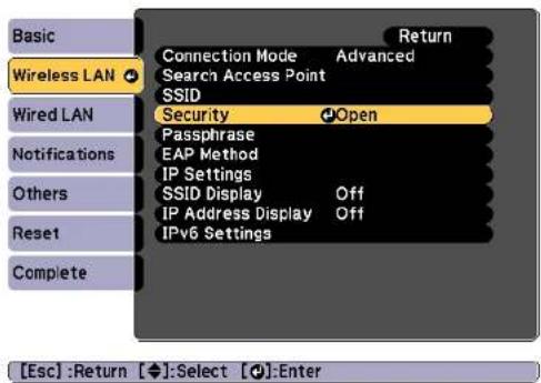
text_image
Basic Wireless LAN Wired LAN Notifications Others Reset Complete Return Connection Mode Advanced Search Access Point SSID Security Open Passphrase EAP Method IP Settings SSID Display Off IP Address Display Off IPv6 Settings [Esc] :Return [◆]:Select [●]:Enter7 Select the security settings to match your network settings.
•WPA2-PSK, WPA/WPA2-PSK:
Select Setup complete. Follow the on-screen instructions to save the settings and close the menu.
•WPA2-EAP, WPA/WPA2-EAP:
Select EAP Method and press [Enter].
8 Select the protocol for authentication as the EAP Type setting.
9 To import your certificate, select the certificate type and press [Enter].
- Client Certificate for the PEAP-TLS or EAP-TLS type
- CA certificate for the PEAP, PEAP-TLS, EAP-TLS, or EAP-FAST type

You can also register the digital certificates from your Web browser. However, be sure to register just once or the certificate may not install correctly.
"Setting a certificate using a Web browser" p.133
10 Select Register and press [Enter].
11 Connect a USB storage device to the projector's USB-A port (the wireless LAN module installation section).
If the wireless LAN module is already installed in the projector, remove it.
"Installing the Wireless LAN Unit" p.54
12 Press [Enter] to display the certificate list.
13 Select the certificate to import using the displayed list. A message is displayed prompting you to enter the password for the certificate.
14 Enter a password and press [Enter].
The certificate is imported and a completion message appears.
15 Select your EAP settings as necessary.

text_image
[EAP Method] Return Wireless LAN EAP Type PEAP User name Password Client Certificate Verify Server Cert. Off CA certificate RADIUS Serv.Name [Esc] / [◆]:Return [◆]:Select- User Name: Enter the user name. You can enter up to 64 single-byte alphanumeric characters. When entering more than 32 characters, use your Web browser to enter the text. When importing a client certificate, the name the certificate was issued to is automatically set.
- Password: Enter the password used for authentication in PEAP, EAP-FAST, and LEAP. You can enter up to 64 single-byte alphanumeric characters. When entering more than 32 characters, use your Web browser to enter the text.
- Verify Server Cert. lets you select whether or not to verify the server certificate when a CA certificate has been set.
- RADIUS Serv.Name lets you enter the server name to be verified.
16 If you have finished making settings, select Setup complete.
Follow the on-screen instructions to save the settings and close the menu.
Supported Client and CA Certificates
You can register these types of digital certificates.
Client Certificate (PEAP-TLS/EAP-TLS)
| Item Explanation | |
| Format | PKCS#12 |
| Extension | PFX, P12 |
| Encryption | RSA |
| Hashes | MD5/SHA-1/SHA-256/SHA-384/SHA-512 |
| Key length | 512/1024/2048/4096 bit |
| Password * | You need to setup a password. Up to 32 single-byte alphanumeric characters |
CA Certificate (PEAP/PEAP-TLS/EAP-TLS/EAP-FAST)
| Item Explanation | |
| Format | X509v3 |
| Extension | DER/CER/PEM |
| Encryption | RSA |
| Hashes | MD5/SHA-1/SHA-256/SHA-384/SHA-512 |
| Key length | 512/1024/2048/4096 bit |
| Encoding | BASE64/Binary |
* You can set a password using up to 64 alphanumeric characters. When entering more than 32 characters, use your Web browser to enter the text.
"Changing Settings Using a Web Browser (Epson Web Control)" p.215
Using a QR Code to Connect a Mobile Device
After making the wireless network settings for your projector, you can display a QR code on the screen and use it to connect a mobile device using the Epson iProjection (iOS/Android) app.

- Make sure you have installed the latest version of Epson iProjection on your device (Epson iProjection V1.3.0 or later supports this feature).
- You can download Epson iProjection for free from the App Store or Google Play. Any fees incurred when communicating with the App Store or Google Play are the responsibility of the customer.
- When using Epson iProjection in Quick connection mode, we recommend making security settings.

Press the [LAN] button on the remote control.
The QR code is displayed on the projected surface.

- If you do not see the QR code, set the Display LAN Info. setting to Text & QR Code in the projector's Network menu.
Network - Network Configuration - Display LAN Info. p.153
•To hide the QR code, press the Esc button.
- When the QR code is hidden, press the [Enter] button to display the code.
- You can also display the QR code by selecting the icon on the Home screen.

Start Epson iProjection on your mobile device.

Read the projected QR code using Epson iProjection to connect it to the projector.

To correctly read the QR code, make sure you face the screen squarely and closely enough so that the projected code fits into the guide of the mobile device's QR code reader. If you are too far from the screen, the code may not be read.
When a connection is established, select Contents menu from , and then select the file you want to project.
Using a USB Key to Connect a Windows Computer
You can set up your USB flash drive as a USB key to quickly connect the projector to a wireless LAN supported Windows computer. The USB key allows you to automatically select a computer's wireless network settings and project your presentation wirelessly.
1 Set up the USB key using Epson iProjection (Windows). See the "Epson iProjection Operation Guide (Windows/Mac)" for instructions.
2 Make sure the wireless LAN module is installed.
3 Turn on the projector.
4 Press the [LAN] button on the remote control.
The LAN standby screen is displayed. Verify that an SSID and IP address are displayed.
5 Remove the wireless LAN module from the projector and insert the USB key into the same port used for the wireless LAN module.
"Installing the Wireless LAN Unit" p.54
You see a projected message that the network information update is complete.
6 Remove the USB key.
Reinsert the wireless LAN module into the projector.
7 Connect the USB key to a USB port on your computer.
8 Follow the on-screen instructions to install the necessary application.

- If the Windows Firewall message is displayed, click Yes to disable the firewall.
- You need administrator authority to install the software.
- If it is not installed automatically, double-click MPPLaunch.exe in the USB key.
After a few minutes, your computer image is displayed by the projector. If it does not appear, press the [LAN] button on your projector's remote control or restart your computer.
9 Run your presentation.
10 When you have finished projecting wirelessly, select the Safely Remove Hardware option in the Windows taskbar, and then remove the USB key from your computer.

You may need to restart your computer to reactivate your wireless LAN connection.
Secure HTTP

You can use the HTTPS protocol to increase security between the projector and a Web browser communicating with it. To do this, you create a server certificate, install it on the projector, and turn on the Secure HTTP setting in the projector menus to verify the reliability of the Web browser.
Network - Network Configuration - Others - Secure HTTP p.159
Even if you do not install a server certificate, the projector automatically creates a self-signed certificate and allows communication. However, because the self-signed certificate cannot verify reliability from a Web browser, you see a warning about the server's reliability when you access the projector from a Web browser. This warning does not prevent communication.
Importing a Web Server Certificate Using the Menus
You can create your Web server certificate, and import it using the projector menus and a USB flash drive.

You can also register the digital certificates from your Web browser. However, be sure to register just once or the certificate may not install correctly.
p.133
1 If you want to set up the WPA2-EAP or WPA/WPA2-EAP security, make sure your digital certificate file is compatible with projector registration and placed directly on the USB storage device.
"Supported Web Server Certificates" p.133
2 Press the Menu button on the control panel or remote control.
3 Select the Network menu and press [Enter].
4 Select Network Configuration and press [Enter].
5 Select the Others menu and press [Enter].

text_image
Basic Wireless LAN Wired LAN Notifications Others Reset Complete Secure HTTP Off Web Server Cert. Priority Gateway Wired LAN AMX Device Discovery Off Crestron Connected Off Message Broadcasting Off Return [Esc] / [◆]: Return [◆]: Select6 Select On as the Secure HTTP setting.
7 Select Web Server Cert. and press [Enter].
8 Select Register and press [Enter].
9 Connect a USB storage device to the projector's USB-A port (the wireless LAN module installation section).
If the wireless LAN module is already installed in the projector, remove it.
"Installing the Wireless LAN Unit" p.54
10 Press [Enter] to display the certificate list.
11 Select the certificate to import using the displayed list. A message is displayed prompting you to enter the password for the certificate.
12 Enter a password and press [Enter].
The certificate is imported and a completion message appears.
Supported Web Server Certificates
You can register these types of digital certificates.
Web Server Certificate (Secure HTTP)
| Item Explanation | |
| Format | PKCS#12 |
| Extension | PFX, P12 |
| Encryption | RSA |
| Hashes | MD5/SHA-1/SHA-256/SHA-384/SHA-512 |
| Key length | 512/1024/2048/4096 bit |
| Common Name | Network IHost Name |
| Organization | Optional |
| Password * | You need to setup a password. Up to 32 single-byte alphanumeric characters |
* You can set a password using up to 64 alphanumeric characters. When entering more than 32 characters, use your Web browser to enter the text.
"Setting a certificate using a Web browser" p.133
Setting a certificate using a Web browser
You can use an electronic certificate as the projector's security settings.

You can install the electronic certificate from the projector's Network menu. However, be sure to register just once or the certificate may not install correctly.
"Setting Up Wireless Network Security" p.127
1 Prepare a certificate that is supported by the projector.
2 Make sure the projector is turned on.
3 Launch the Web browser on the computer or mobile device connected to the network.
4 Enter the IP address of the projector in the address input box of the browser to connect to the Epson Web Control screen. The Epson Web Control screen is displayed.
5 Select Advanced.

You need to login to display the Advanced screen. When the login screen is displayed, enter your user name and password. (The user name is EPSONWEB; the default password is admin.)
6 Select Certificate from Network.
7 Click the Choose File button, select the certificate file.
8 Enter the password in the Password box, and then click Send.
9 When the settings are complete, click the Apply.

Configuration Menu
This chapter explains how to use the Configuration menu and its functions.
Configuration Menu Operations

This section explains how to use the Configuration menu.
Although steps are explained using the remote control as an example, you can perform the same operations from the control panel. Check the guide under the menu for the available buttons and their operations.
1 Display the Configuration menu screen.


text_image
Image Signal Settings Extended Network Info Reset Color Mode Photo Brightness 0 Contrast 0 Color Saturation 0 Tint 0 Sharpness White Balance Image Enhancement Advanced Light Source Control Off Reset ReturnEsc / [●]: Return [●]: Select Menu: Exit
2 Select a top menu item.
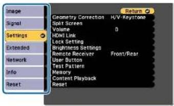
text_image
Image Signal Settings Extended Network Info Reset Geometry Correction H/V Keystone Spot Screen Volume 0 HDMI Link Lock Setting Brightness Settings Remote Receiver Front/Rear User-Button Test Pattern Memory Content Playback Reset ReturnEsc / [●]: Return ◆: Select Menu: Exit
3 Select a submenu item.

text_image
Geometry Correction H/V-Keystone Split Screen Volume 0 HDMI Link Lock Setting Brightness Settings Front/Rear Remote Receiver User Button Test Pattern Memory Content Playback Reset [Esc]:Return Select Enter [Menu]:Exit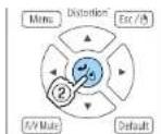
4 Change settings.


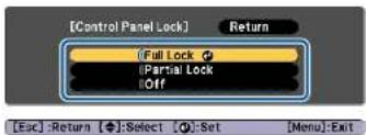
text_image
[Control Panel Lock] Return (Full Lock) (Partial Lock) Off [Esc]:Return [◆]:Select [O]:Set [Menu]:Exit
When "[Default]: Reset" is displayed on the guide under the menu, pressing the [Default] button on the remote control returns the settings being adjusted to their default values.
5 Press the [Menu] button to finish making settings.
Configuration Menu Table
Settable items vary depending on the model being used and the image signal and source being projected.
| Top Menu Name Submenu Name Items or Setting Values | |
| Image menup.140 | Color Mode Dynamic, Presentation, Natural,Cinema, B'1.709, DICOM SIM,Multi-Projection |
| Brightness 0 to 100 | |
| Contrast 0 to 100 | |
| Color Saturation 0 to 100 | |
| Tint 0 to 100 | |
| Sharpness Standard, Thin Line Enhancement,Thick Line Enhancement | |
| White Balance Color Temp., G-M Correction,Offset R, Offset G, Offset B, Gain R,Gain G, Gain B | |
| Image Enhancement 4K Enhancement, Image PresetMode, Frame Interpolation,Deinterlacing, Noise Reduction,MPEG Noise Reduction, Super-resolution, Detail Enhancement,Reset | |
| Advanced Gamma, RGB CMY | |
| Light Source Control Light Source Control, DynamicContrast, Lights-Out Control | |
| Signal menup.142 | Resolution Auto, Wide, Normal, and Manual |
| Aspect Auto, Normal, 4:3, 16:9, Full, H-Zoom, V-Zoom, Native | |
| Tracking - | |
| Sync. 0 to 31 | |
| Top Menu Name Submenu Name Items or Setting Values | ||
| Position | -128 to 127 | |
| Auto Setup | On, Off | |
| Overscan | Auto, Off, 4%, and 8% | |
| Blanking | Top, Bottom, Left, and Right | |
| Advanced Video Range, Input Signal, BNC Sync Termination, EDID, DDC Buffer | ||
| Scale | Scale, Scale Mode, Scale Vertically, Scale Horizontally, Clip Adjustment, Clip Range | |
| Settings menup.143 | Geometry Correction | Off, H/V-Keystone, Quick Corner, Curved Surface, Corner Wall, Point Correction, Memory |
| Split Screen | - | |
| Volume | 0 to 20 | |
| HDMI Link | Device Connections, HDMI Link, Audio Out Device, Power On Link, Power Off Link, Link Buffer | |
| Lock Setting | Control Panel Lock, Lens Lock | |
| Brightness Settings | Light Source Modc, Brightness Level, Constant Brightness, Estimated Remains | |
| Remote Receiver | Front/Rear, Front, Rear, and Off | |
| User Button User Button | 1, User Button 2, and User Button 3 | |
| Test Pattern Standard, Cross-hatching, Cross-hatching R, Cross-hatching G, Cross-hatching B, Color Bars V, Color Bars H, Grayscale, Gray Bars V, Gray Bars H, Checkerboard 1, Checkerboard 2, White, Black, Aspect Frame | ||
| Memory Memory, Lens Position, Geometry Correction | ||
| Content Playback Content Playback, Overlay Effect, USB Viewer | ||
| Extended menu p.146 | Home Screen Home Screen Auto Disp., Custom Function 1, Custom Function 2 | |
| Display Menu Position, Message Position, Messages, Display Background, Startup Screen, Standby Confirmation, Air Filter Notice, Screen, Panel Alignment, Color Uniformity, OSD Rotation | ||
| User's Logo Start Setting, Reset | ||
| Projection Front, Front/Ceiling, Rear, and Rear/Ceiling | ||
| Operation Direct Power On, Sleep Mode, Sleep Mode Timer, High Altitude Mode, Auto Source Search, Auto Power On, Startup Source, A/V Mute Settings, Advanced, Date & Time, Lens Calibration | ||
| A/V Settings A/V Output, Monitor Out, and Audio Settings | ||
| Standby Mode Communication On and Communication Off | ||
| HDBaseT Control Communications, Extron XTP | ||
| Multi-Projection Projector ID, Tiling, Geometry Correction, Edge Blending, Black Level, Scale, Color Mode, Brightness Settings, Color Matching, Color Uniformity, Reset | ||
| Schedule Settings - | ||
| Top Menu Name Submenu Name Items or Setting Values | ||
| Language | 27 languages | |
| Info menu p.161 | Projector Info | Total Op. Time, Operation Hours, Source, Input Signal, Resolution, Refresh Rate, Sync Info, Status, Serial Number, Lens Type, Event ID, HDBaseT Signal Level |
| Light Source Info Light Source Hours, Estimated Remains | ||
| Version | Main, Video2, Sub, Sub2, HDMI, IIDBaseT, IIDBaseT2 | |
| Status Information | Status Information, Source, Signal Information, Network Wired, Network Wireless, Maintenance, Version | |
| Temp Warning Info | - | |
| Power On/Off History | - | |
| Reset menu p.162 | Reset All Memories | - |
| Refresh Mode | Timer, Messages, Start | |
| Light Source Calibration | Run Now, Run Periodically, Schedule Settings, Last Run | |
| Reset All Config | - | |
| Reset All (Factory Default) | Reset All (Factory Default), Password | |
Network menu
| Top Menu Name | Submenu Name | Items or Setting Values |
| Basic menu p.153 | Projector Name | - |
| PJLink Password | - | |
| Remote Password | - | |
| Top Menu Name Sub menu Name Items or Setting Values | ||
| Web Control Password - | ||
| Moderator Password - | ||
| Projector Keyword On, Off | ||
| Display Keyword On, Off | ||
| Display LAN Info. Text & QR Code, Text | ||
| Wireless LAN menu p.154 | Connection Mode Quick, Advanced | |
| Search Access Point - | ||
| SSID - | ||
| Security Open, WPA2-PSK, WPA/WPA2-PSK, WPA2-EAP, WPA/WPA2-EAP | ||
| Passphrase - | ||
| EAP Method EAP Type, User name, Password, Client Certificate, Verify Server Cert., CA certificate, RADIUS Serv.Name | ||
| Channel 1ch, 6ch, and 11ch | ||
| IP Settings | DHCP, IP Address, Subnet Mask, Gateway Address | |
| SSID Display | On, Off | |
| IP Address Display | On, Off | |
| IPv6 Settings IPv6, Auto Configuration, Use Temporary Address | ||
| Wired LAN menu p.157 | IP Settings | DHCP, IP Address, Subnet Mask, Gateway Address |
| IP Address Display | On, Off | |
| Top Menu Name | Submenu Name | Items or Setting Values |
| IPv6 Settings IPv6, Auto Configuration, Use Temporary Address | ||
| Notifications menu p.159 | Mail Notification | On, Off |
| SMTP Server | - | |
| Port Number | - | |
| From | - | |
| Address 1 Setting, Address 2 Setting, Address 3 Setting | Email Address, No Signal, System Error, Laser Error, High Temp Error, Air Filter Error, Laser Warning, High Temp Warning, Air Filter Warning, Air Filter Notice, Constant Bright. End | |
| SNMP | On, Off | |
| Trap IP Address 1, Trap IP Address 2 | - | |
| Community Name | - | |
| PJLink Notification | On, Off | |
| Notified IP Address | - | |
| Others menu p.159 | Secure HTTP | On, Off |
| Web Server Cert. | - | |
| Priority Gateway | Wired LAN, Wireless LAN | |
| AMX Device Discovery | On, Off | |
| Crestron Connected | On, Off | |
| Message Broadcasting | On, Off | |
Image Menu
Settable items vary depending on the image signal and source currently being projected. Setting details are saved for each color mode.
"Automatically Detecting Input Signals and Changing the Projected Image (Source Search)" p.61
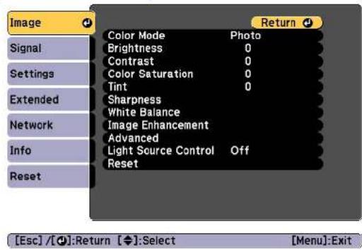
text_image
Image Signal Settings Extended Network Info Reset Color Mode Photo Brightness 0 Contrast 0 Color Saturation 0 Tint 0 Sharpness White Balance Image Enhancement Advanced Light Source Control Off Reset [Esc] / [◆]:Return [◆]:Select [Menu]:Exit| Submenu Function | |
| Color Mode | You can select the quality of the image to suit your surroundings. "Selecting the Projection Quality (Selecting Color Mode)" p.76 |
| Brightness | Adjusts the image brightness. |
| Contrast | Adjusts the difference between light and shade in the images. |
| Color Saturation | Adjusts the color saturation for the images. |
| Tint | You can adjust the image tint. |
| Submenu Function | |
| Sharpness | Standard: You can adjust the image sharpness. Thin Line Enhancement: If this parameter is set to a positive value, details such as hair or fabric patterns will be enhanced. Thick Line Enhancement: If this parameter is set to a positive value, the outline, background, and the other main parts of the objects in the image will be enhanced to show them clearly. |
| White Balance | You can adjust the overall tint of the image. Color Temp.: You can adjust the overall tint of the image within a range from 3200K to 10000K. The image is tinted blue when a high value is selected and tinted red who low value is selected. When Color Mode is set to Dynamic, the set Color Temp. may differ from the actual Color Temp. of the light from the projector. Use this menu as a guide G-M Correction: The color tone is tinted red when set to a negative value, and tinted green when set to a positive value. Offset R/G/B, Gain R/G/B: You can adjust the offset and gain of each color R (red), G (green), and B (blue) individually. |
| Submenu Function | |
| Image Enhancement | You can adjust the image resolution.◆ "Adjusting Image Resolution (Image Enhancement)" p.834K Enhancement*: (FB-L1075U/EB-L1070U/FB-L1065U/FB-L1060U/EB-L1050U only) You can project at a doubled resolution.Image Preset Mode: You can select the optimal setting according to the projected image from five presets prepared in advance.Frame Interpolation: You can play fast moving images smoothly by producing intermediate frames between the original frames.Deinterlacing: (Only when the input signal is 480i, 576i, or 1080i) You can convert interlace signals into progressive signals. (IP conversion)Off is ideal for images with a large amount of movementVideo for general video images, and Film/Auto for movie films, computer graphics, and animation.Noise Reduction: You can smooth out the roughness in progressive images.MPEG Noise Reduction: You can reduce dot and block noise that occurs in outlines when projecting MPEG movies.Super-resolution: To display a crisp image, you can reduce the blurring that is created on the edge when the resolution of the image signal is scaled up and projected.Detail Enhancement: You can enhance the contrast of details in an image.Reset: Returns the selected preset to its defaults. |
| Advanced | You can make adjustments by choosing the following items.Gamma: You can adjust the coloring by selecting one of the gamma correction values, or referring to the projected graph.RGBCMY: You can adjust the hue, saturation, and brightness of each color R (red), G (green), B (blue), C (cyan), M (magenta), Y (yellow) individually. |
| Submenu Function | |
| Light Source Control | Light Source Control: Select the light source operations according to the image signal.➤ "Setting the Amount of Light of the Projected Image p.79Dynamic Contrast: (This can only be set if Light Source Control is set to Dynamic Contrast) Automatically adjusts the amount of light when projecting according to the brightness of the image.Lights-Out Control: (This can only be set if Light Source Control is set to Lights-Out Control) Automatically turns off the light after the set time has elapsed at the specified video level. |
| Reset | You can reset all adjustment values for the Image menu to their default settings. See the following to return all menu items to their default settings.➤ "Reset Menu" p.162 |
* This cannot be set when Aspect is set to Native.
Signal Menu
Settable items vary depending on the image signal and source currently being projected. Setting details are saved for each image signal.

text_image
Image Signal Settings Extended Network Info Reset Resolution Auto Aspect 4:3 Tracking 0 Sync. 0 Position Auto Setup Off Blanking Advanced Scale Reset [Esc] / [●]:Return [◆]:Select [Menu]:Exit| Submenu Function | |
| Resolution | (Only available when an analog RGB computer signal is being input.)Set toAutoto automatically identify the resolution of the input signal. If images are not projected correctly when set toAuto, for example if some of the image is missing, set toWidefor wide screens, or set toNormalfor 4:3 or 5:4 screens depending on the connected computer.Manual allows you to specify theresolution. This is ideal when connected computer is fixed. |
| Aspect | You can set the Aspect Ratio for projected images."Changing the Aspect Ratio of the Projected Image" p.80 |
| Tracking | (Only available when an analog RGB computer signal is being input.)You can adjust computer images when vertical stripes appear in the images. |
| Submenu Function | |
| Sync. | (Only available when an analog RGB computer signal is being input.)You can adjust computer images when flickering, fuzziness, or interference appear in the images. |
| Position | You can adjust the display position up, down, left, and right when a part of the image is missing so that the whole image is projected. |
| Auto Setup | (Only available when an analog RGB computer signal is being input.)Set to On to automatically adjust Tracking, Sync., and Position to the optimum state when the input signal changes. |
| Overscan | Changes the output image ratio (the range of the projected image). You can set the cropping range to 4% or 8%. When set to Auto, this is automatically adjusted according to the input signal. |
| Blanking | You can hide images in the set area. Use the [◀]▶buttons to adjust the area. You can adjust by using a combination of Top, Bottom, Left, and Right. You can hide up to half of the projected image in each direction (except for one pixel). |
| Advanced | You can set by choosing the following items.Video Range: Select the video range for the input signal from the HDMI port, DVI-D port, or HDBaseT port. If the brightness range is 16 to 235, select Limited (16-235), if it is 0 to 255, select Full (0-255).Input Signal: Select an input signal from the Computer port or BNC port. If set to Auto, the input signal is set automatically according to the connected equipment. If colors do not appear correctly when set to Auto, select the appropriate signal according to the connected equipment.BNC Sync Termination: Set the end process for signals from the BNC In port. This should usually be set to Off. Set to On when analog (75Ω) termination such as for switchers is necessary.EDID: (Displayed when the current source is HDMI, HDBaseT, or DVI-D) Make settings related to EDID. Even in setups with multiple displays with different resolutions, you can switch the EDID of the current source and unify the EDID across the displays by setting the same EDID as the standard display.Preset EDID: Select the optimal setting from the presets prepared in advance. Change the preset sub menu settings for Resolution, Refresh Rate, and Color Depth if necessary. Select Settings, and then press the [←] button.Resolution: Select from the resolutions displayed.Refresh Rate: Select from the refresh rates displayed.Color Depth: Select the maximum color depth limit supported by the projector. When you select 12bit, the projected images support signals up to 12 bits.Reset: You can reset all adjustment values for EDID to their default values.DDC Buffer: (Displayed when the current source is HDMI or DVI-D) Setting this to On can sometimes improve images that are not displayed correctly from devices connected using an HDMI or DVI extension cable. |
| Scale | When using multiple projectors to project one image, adjust the range of the image displayed by each projector."Displaying a Scaled Image" p.97 |
| Submenu Function | |
| Reset | You can reset all adjustment values on the Signal menu to their default settings, except for Input Signal and EDID.See the following to return all menu items to their default settings."Reset Menu" p.162 |
Settings Menu
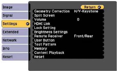
text_image
Image Signal Settings Geometry Correction H/V-Keystone Spit Screen Volume 0 HDMI Link Lock Setting Brightness Settings Remote Receiver Front/Rear User Button Test Pattern Memory Content Playback ResetEsc / [●]: Return ◆: Select Menu: Exit
| Submenu Function | |
| Geometry Correction | You can correct distortion.➤ "Correcting Distortion in the Projected Image" p.64➤Off:Temporarily cancels the geometry correction.➤H/V-Keystone:Adjust V-Keystone, V-Balance, H-Keystone, and H-Balance to correct vertical and horizontal keystone distortion.➤Quick Corner:Select and correct the four corners of the projected image.➤Curved Surface:Corrects distortion that occurs when projecting on a curved surface.➤Corner Wall:Corrects distortion that occurs when projecting on a surface with right angles.➤Point Correction:Divides the projected image into a grid and corrects the distortion by moving the selected point of intersection from side to side and up and down.➤Memory:You can save the adjustment value of the geometry correction and load it when needed.➤ "Memory Function" p.110 |
| Split Screen | You can split the screen into two screens.➤ "Projecting Two Images Simultaneously (Split Screen)" p.99 |
| Volume | You can adjust the volume. Setting values are saved for each source. |
| Submenu Function | |
| HDMI Link | Sets HDMI Link.Device Connections:Displays a list of the devices connected to the HDMI port.HDMI LinkEnables or disables HDMI Link.Audio Out Device:When the projector is connected to an AV amplifier, select whether to output audio from the external speakers connected to the projector or to output audio from the AV amplifier's speakers.Power On Link:Set the operation to perform when turning on the projector or a connected device.Bidirectional:Turns on the connected device when the projector is turned on, or turns on the projector when the connected device is turned on-connected Device→PJ:Turns on the projector when the connected device is turned on.PJ→Connected Device:Turns on the connected device when the projector is turned on.Power Off Link:Set whether or not to turn off the connected device when the projector is turned off.Link Buffer:If HDMI Link is not working properly, changing this setting may improve linking operations. |
| Lock Setting | Control Panel Lock:You can use this to restrict operation of the projector's control panel."Control Panel Lock" p.117Lens Lock:When set to On,[Lens Shift],[Zoom], and [Focus] button operations on the remote control are disabled."Lens Lock" p.118 |
| Submenu Function | Submenu Function | ||
| Brightness Set- tings | Light Source Mode: Set the brightness for the light source.Normal: Select this if you do not want to decrease the brightness. This makes the light source operation time approximately 20,000 hours.Medium: Noise from the fan is louder than when Quiet is selected, but it does not decrease the brightness as much. This sets the brightness at 85%. This makes the light source operation time approximately 20,000 hours.Quiet: Select this if you are concerned about the noise made by the fan. This sets the brightness at 70%. This makes the light source operation time approximately 20,000 hours.Extended: Select this to extend the life expectancy of the light source. This sets the brightness at 70%. This makes the light source operation time approximately 30,000 hours.Custom: Select this to set the brightness level within a range of 30 to 100%.Brightness Level: (Only available when Light Source Mode is set to Custom) Sets the brightness for the light source. Constant Brightness: (Only available when Light Source Mode is set to Custom) When set to On, the brightness of the light source set in Brightness Levld is maintained as it is. When Constant Brightness is set to On, you cannot change the settings for Light Source Mode and Brightness Level."Setting the Brightness" p.77Estimated Remains: When Constant Brightness is set to On, this indicates the amount of time for which constant brightness can be maintained."Guide to Estimated Remains" p.78 | Remote Receiver | You can limit the reception of the operation signal from the remote control.When set to Off, you cannot perform any operations from the remote control. If you want to make operations from the remote control, hold down the [Menu] button on the remote control for at least 15 seconds to reset the setting to its default value. |
| User Button | Select the items in the Configuration menu that you want to assign to the [User1], [User2], and [User3] buttons on the remote control. The following items can be assigned.Light Source Mode, Multi-Projection, Resolution, On-Screen Display, Display the QR Code, Image Enhancement, Frame Interpolation, Link Menu, Content Playback, USB(USB is only enabled when Content Playback is set to On.) | ||
| Test Pattern | You can display a test pattern to adjust the projection without connecting other equipment when you set up the projector."Displaying the Test Pattern" p.33 | ||
| Memory | Perform operations and make settings for the memory function."Memory Function" p.110 | ||
| Content Play-back | Content Playback: When this is set to On, you can play playlists created in Epson Projector Content Manager. Overlay Effect: Adds color and shape decorations to the image. (This is only enabled when Content Playback is set to On.)USB Viewer: Plays playlists stored on a USB flash device. (This is only enabled when Content Playback is set to On.) | ||
| Submenu Function | |
| Reset | You can reset all adjustment values on the Settings menu to their default settings, except for Audio Out Device, Power On Link, Power Off Link, Link Buffer, User Button, Memory, Content Playback.See the following to return all menu items to their default settings."Reset Menu" p.162 |
* This cannot be set when Edge Blending is set to On
Extended Menu
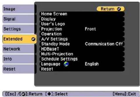
text_image
Image Signal Settings Extended Network Info Reset Home Screen Display User's Logo Projection Front Operation A/V Settings Standby Mode Communication Off HDBaseT Multi-Projection Schedule Settings Language English Reset Return [Esc] / [◆]: Return [◆]: Select [Menu]: Exit| Submenu Function | |
| Home Screen | Home Screen Auto Disp.: When set to On, the Home screen is displayed when the projector turns on. The Home screen is not displayed when the selected source has an image signal when the projector turns on.Custom Function 1, Custom Function 2: Select functions to be assigned to the Home screen from the following five functions. Network Settings, Info, Image Enhancement, Frame Interpolation, Split Screen |
| Display | You can make settings related to the projector's display.Menu Position: Select the position to display the menu on the projected screen.Message Position: Select the position to display the message on the projected screen.Messages: When set to Off, the following items will not be displayed.Item names when the Source, Color Mode, or Aspect is changed, messages when no signal is being input, and warnings such as High Temp Warning.Display Background: You can set the screen background to Black, Blue, or Logo when no image signal is available.Startup Screen*: Set to On to display the User's Logo when you start projecting.Standby Confirmation: If it is set to Off, you can turn off the power simply by pressing the [O] button once.Air Filter Notice: You can set whether or not (On/Off) to enable Air Filter Notice. When this is set to On and a clog in the air filter is detected, the message is displayed on the screen.Screen: (This is unavailable when projecting images from a computer over a network.) Set the aspect ratio and position of the projected screen according to the screen being used."Screen Settings" p.32Panel Alignment: Corrects color misalignments (red and blue) in the screen."Panel Alignment" p.210Color Uniformity: Adjusts the color tone balance for the whole screen."Color Uniformity" p.212OSD Rotation: Rotates the menu direction by 90° degrees. |
| User's Logo * | You can change the user's logo that is displayed as a background during Display Background, A/V Mute, and so on."Saving a User's Logo" p.104 |
| Submenu Function | |
| Projection | Select from one of the following projection methods depending on how the projector is installed.Front, Front/Ceiling, Rear, Rear/CeilingYou can change the setting as follows by pressing down the [A/V Mute] button for about five seconds.Front ↔ Front/CeilingRear ↔ Rear/Ceiling |
Submenu Function
| Operation | Direct Power On: Set to On to turn on the projector simply by plugging it in.When the power cord is plugged in, note that the projector turns on automatically in cases such as a power outage being restored.Sleep Mode: When set to On, this automatically stops projection when no image signal is being input and no operations are carried out.Sleep Mode Timer: When Sleep Mode is set to On, you can set the time before the projector automatically turns off within a range of 1 to 30 minutes.High Altitude Modc: Set this to On if you are using the projector above an altitude of 1,500 meters.Auto Source Search: Set to On to automatically detect an image signal from another source and project the image when there is no image signal from the current source.Auto Power On: If it is set to Computer or BNC, the projector is turned on when the signals are received from the Computer port or BNC port, even when the projector is in standby status.Startup Source: Select the source you want to project when the projector is turned on in Content Playback mode.A/V Mute Settings: Perform settings related to A/V mute.Fadc-in: Specify the number of seconds for fade-in when displaying an image.Fade-out: Specify the number of seconds for fade-out when hiding an image.A/V Mute Timer: When it is set to On, if no operations are performed for about 2 hours after A/V mute is activated, the projector turns off automatically.A/V Mute Release: When it is set to A/V Mute, you can release A/V mute only by pressing the [A/V Mute] button (or by sending an A/V mute Off command).When set to Any Button, A/V mute is released when any operation is performed on the projector. |
Submenu Function
| ◆ "Hiding the Image and Sound Temporarily (A/V Mutc)" p.102Advanced: The following items can be set.● Beep: When this is set to On, the confirmation buzzer beeps to notify you that the power turns on or off, cooling down is finished.● Indicators: When set to Off, the projector's indicators are turned off, except for abnormality or warning.● Log Save Destination: Set where you want to save the operation logs for the projector. Select USB and Internal Memory to save the logs to the USB flash drive connected to the projector's USB-A port. Logs are saved as text files (.log) on the USB flash drive.The following logs are saved.- Error information- Laser information- Temperature logs- Operation logs● Batch Setup Range: Select All to copy all of the menu settings using the batch setting function. Select Limited if you do not want to copy the following settings.- EDID from the Signal menu- Network menu● Lens Type: When using the following lens, select the model number of the lens.ELPLS04, ELPLU02, ELPLR04, ELPLW04, ELPLM06, ELPLM07, ELPLL07Date & Time: Make system time settings for the projector.◆ "Setting the Time" p.44Lens Calibration: Acquires the information of the lens installed on the projector. | |
| Submenu Function | |
| A/V Settings | A/V Output: Set this to Always On if you want to output audio and images to an external device even when the projector is in standby status.Monitor Out: Select the image source output to an external monitor when the projector is in standby status. When set to Auto, analog RGB signals from the Computer port or the BNC port are output depending on which source was selected when the projector was turned off.Audio Settings: Performs the following audio related settings.·Audio Output: Select the audio to be output when projecting images from the Computer port, BNC port, or DVI-D port. When set to Auto, audio is output from the audio input port corresponding to each image input port. "Connecting Equipment" p.47·HDMI Audio Output: Select the audio source when projecting images from the HDMI port. If you select HDMI, audio for the image is output as it is. If you select Audio3, audio is output from the Audio3 port. |
| Standby Mode | If you set Communication On, you can perform the following operations even if the projector is in standby mode.·Monitor and control the projector over a network.·Output audio and images to an external device. (Only when A/V Output is set to Always On.)·Communication from the HDBaseT port is enabled. (Only when Control Communications is set to On.)When monitoring or controlling the projector using wireless LAN, set Connection Mode to Advanced.Network - Wireless LAN - Connection Mode p.154 |
| Submenu Function | |
| HDBaseT | Control Communications: (This cannot be set when Extron XTP is set to On.) When set to On, Ethernet communication, serial communication, and the wired remote control through the HDBaseT Transmitter connected to the HDBaseT port are all enabled.Extron XTP: Set to On when you connect the Extron XTP transmitter or switcher to the HDBaseT port. See the following Extron Web site for more details on the XTT system.http://www.extron.com/ ·When Control Communications or Ex-tron XTP is set to On, Standby Mode is automatically set to Communication On, ·When Control Communications or Ex-tron XTP is On, the projector's LAN port, RS-232 port, and Remote port are disabled. ·When Extron XTP is set to On, the fan may rotate in standby mode but this is not abnormal. ·When Control Communications or Ex-tron XTP is set to On, Standby Mode is automatically set to Communication On, ·When Control Communications or Ex-tron XTP is On, the projector's LAN port, RS-232 port, and Remote port are disabled. ·When Extron XTP is set to On, the fan may rotate in standby mode but this is not abnormal. |
| Submenu Function | |
| Multi-Projection | Make settings when projecting from multiple projectors. "Multi-Projection Function" p.90Projector ID: Set the ID from 01 to 30. Off indicates that no ID is set. "ID Settings" p.42Tiling: Set the number of split screens and positions of each projected image. "Tiling" p.90Geometry Correction: Corrects distortion in the projected image. "Correcting Distortion in the Projected Image" p.61Edge Blending: Corrects a border between multiple images to create a seamless screen. "Edge Blending" p.91Black Level: Adjusts the differences in brightness and tone for areas where images overlap and areas where the images do not overlap. "Black Level" p.93Scale: When using multiple projectors to project one image, adjust the range of the image displayed by each projector. "Displaying a Scaled Image" p.97Color Mode: Select the appropriate color mode according to the type of image and the surroundings. Select the same color mode for all projectors.Brightness Settings: Set the brightness for the light source. "Setting the Brightness" p.77Color Matching: Corrects the differences in the tint and brightness between images. "Color Matching" p.96Color Uniformity: Adjusts the color tone balance for the whole screen. "Color Uniformity" p.212Reset: You can reset all adjustment values for the Multi-Projection menu to their default settings. |
| Submenu Function | |
| Schedule Settings | You can set the projector's schedule so that it perform specific operation at a pre-scheduled time. "Scheduling Function" p.112 |
| Language | You can set the language for messages and menus. |
| Reset | You can reset all adjustment values for the Extended menu to their default settings. However, the following items not reset.Screen Type, Screen Position, Panel Alignment, Color Uniformity, Projection, High Altitude Mode, Auto Source Search, A/V Mutc Release, Lens Type, Date & Time, Lens Calibration, A/V Output, Monitor Out, Standby Mode, Control Communications, Extron XTP, Projector ID, Tiling, Edge Blending, Black Level, Scale, Color Modc, Brightness Settings, Color Matching, LanguageSee the following to return all menu items to their defa settings."Reset Menu" p.162 |
* When User's Logo Protection is set to On in Password Protection, you cannot change settings related to user's logo. You can make changes after setting User's Logo Protection to Off.
"Managing Users (Password Protection)" p.115
Network Menu
When Network Protection is set to On in Password Protection, a message is displayed and the network settings cannot be changed. Set Network Protection to Off and then configure the network.
"Setting Password Protection" p.115

text_image
Image Signal Settings Extended Network Info Reset Wireless Mode Net. Info. - Wireless LAN Net. Info. - Wired LAN Display the QR Code Network Configuration Return Wireless L... [Esc] / [◆]:Return [◆]:Select [Menu]:Exit| Submenu Function | |
| Wireless Mode | Set this to Wireless LAN On when connecting the projector and a computer via a wireless LAN. If you do not want to connect via wireless LAN, turn it Off to prevent unauthorized access by others. |
| Submenu Function | |
| Net. Info. - Wireless LAN | Displays the following network setting status information.•Connection Mode•Wireless LAN system•Antenna Level•Projector Name•SSID•DHCP•IP Address•Subnet Mask•Gateway Address•MAC Address•Region CodeWhen IPv6 is selected, the following information is displayed.•IPv6 Address (Manual):IPv6 Address, Prefix Length, Gateway Address•IPv6 Address (Auto):Temporary Address, Link-local Address, Stateless Address, Stateful Address |
| Net. Info. - Wired LAN | Displays the following network setting status information.•Projector Name•DHCP•IP Address•Subnet Mask•Gateway Address•MAC Address•IPv6 Address (Manual):IPv6 Address, Prefix Length, Gateway Address•IPv6 Address (Auto):Temporary Address, Link-local Address, Stateless Address, Stateful Address |
| Display the QR Code | When connecting iOS or Android devices using Epson iProjection, read the QR code displayed. |
Submenu Function
Network Configuration
The following menus are available for setting Network items. Basic, Wireless LAN, Wired LAN, Notifications, Others, Reset
Notes on operating the Network menu
Selecting from the top menu and sub menus, and changing selected items is the same as making operations from the Configuration menu.
When done, make sure you go to the Complete menu, and select Yes, No, or Cancel. When you select Yes or No, you are returned to the Configuration menu.
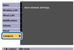
text_image
Basic Wireless LAN Wired LAN Notifications Others Reset Complete 5 Save network settings. Select Enter
Yes: Saves the settings and exits the Network menu.
No: Does not save the settings and exits the Network menu.
Cancel: Continues displaying the Network menu.
Soft keyboard operations
The Network menu contains items that require input of alphanumeric during setup. In this case, the following software keyboard is displayed. Use [▲]||▼||▼ buttons to move the cursor to the desired key, and then press the [▼] button to enter the selected character. Enter figures by holding down the [Num] button on the remote control, and pressing the
numeric buttons. After inputting, press Finish on the keyboard to confirm your input. Press Cancel on the keyboard to cancel your input.

text_image
[SSID] 1 2 3 4 5 6 7 8 9 0 ! " # S A B C D E F G H I 2 & K I M N O P Q R S 0 + CAPS T U V W X Y Z / . SYN2 Backsp Del ← Space AllDel Cancel Finish• Each time the CAPS key is selected and the [◀] button is pressed, it sets and changes between upper case and lower case letters.
• Each time the SYM1/2 key is selected and the [◀] button is pressed, it sets and changes the symbol keys for the section enclosed by the frame.
The following types of character can be entered.
| Numbers | 0123456789 |
| Letters | ABCDEFGHIJKLMNOPQRSTUVWXYZ abcdefghijklmnopqrstuvwxyz |
| Symbols | !" # $ % & ' () * +, - / ;; <= > ? @ [ \ ] ^ _ ' { | } - |
Basic menu

text_image
Basic Wireless LAN Wired LAN Notifications Others Reset Complete Projector Name PJLink Password Remote Password Web Control Password Moderator Password Projector Keyword Off Display Keyword Off Display LAN Info. Text & QR Co... [Esc] /[●]:Return [◆]:Select| Submenu Function | |
| Projector Name | Enter the projector name used to identify the projector over a network.When editing, you can enter up to 16 single-byte alphanumeric characters. (" * + , / : ; <= > ? [ \ ] ' | and spaces cannot be used.) |
| PJLink Password | Set a password to use when you access the projector using compatible PJLink software.You can enter up to 32 single-byte alphanumeric characters.(Spaces and symbols cannot be used.)● "About PJLink" p.227 |
| Remote Pass-word | Set a password to use Remote in Epson Web Control. You can enter up to 8 single-byte alphanumeric characters. (*: and spaces cannot be used.) The default user name is "EPSONREMOTE" and the default password is "guest".● "Changing Settings Using a Web Browser (Epson Web Control)" p.215 |
| Submenu Function | |
| Web Control Password | Set a password for authentication to use when making settings and controlling the projector using Web Control in Epson Web Control. You can enter up to eight single-byte alphanumeric characters (* : and spaces cannot be used). The default user name is "EPSONWEB" and the default password is "admin". ➕ "Changing Settings Using a Web Browser (Epson Web Control)" p.215 |
| Moderator Pass-word | Enter the four digit authentication password for using Epson iProjection when connecting to the projector as a moderator. (There is no default password.) |
| Projector Key-word | Set this to On to enable a security password to prevent other users from accidentally projecting images. When projecting images from a computer or mobile device, you need to enter the keyword displayed on the projection screen in Epson iProjection. |
| Display Keyword | When this is set to On and when connecting to the projector using Epson iProjection, the projector keyword is displayed on the projection screen. This is only enabled when Projector Keyword is set to On. |
| Display LAN Info. | Set the display format for the projector's network information. If you display the QR code, you can connect to a network just by reading the QR code in Epson iProjection. Text & QR Code is set by default. |
Wireless LAN menu
To connect the projector to a computer using a wireless LAN, install the Wireless LAN unit (ELPAP10).
"Installing the Wireless LAN Unit" p.54

text_image
Basic Wireless LAN Wired LAN Notifications Others Reset Complete Connection Mode Advanced Search Access Point SSID Security Open Passphrase EAP Method IP Settings SSID Display Off IP Address Display Off IPv6 Settings Return [Esc] / [●]: Return [◆]: Select| Submenu Function | |
| Connection Mode | Set the connection mode to use when connecting the projector and a computer via a wireless LAN.Quick:Lets you directly connect to a smartphone, tablet, or computer via a wireless LAN.Advanced:Lets you connect to a smartphone, tablet, or computer over a wireless LAN access point. The connection is established in infrastructure mode. |
| Search Access Point | When Connection Mode is set toAdvanced,you can search for surrounding access points, and set the SSID to be connected from those access points. Depending on the access point settings, they may not be displayed in the list."Search Access Point screen"p.156 |
| Submenu Function | |
| SSID | Enter an SSID. When an SSID is provided for the wireless LAN system in which the projector participates, enter the SSID.You can enter up to 32 single-byte alphanumeric characters. |
| Security | Select the security type according to the wireless LAN settings.Open: Security is not set.WPA2-PSK: Communication is performed using WPA2 security. Uses AES method for encryption. When establishing a connection from a computer to the projector enter the value set in the passphrase.WPA/WPA2-PSK*: Connects in WPA personal mode.Encryption method is selected automatically according to the access point settings. Set a passphrase which is the same for the access point.WPA2-EAP*: Communication is performed using WPA2 security. Uses AES method for encryption.WPA/WPA2-EAP*: Connects in WPA enterprise mode.Encryption method is selected automatically according to the access point settings. |
| Passphrase | Enter a passphrase used to connect to the network when Security is set to WPA2-PSK or WPA/WPA2-PSK.You can enter at least 8 and up to 63 single-byte alphanumeric characters.You can enter up to 32 characters on the Configuration menu. When entering more than 32 characters, use your Web browser to enter the text."Changing Settings Using a Web Browser (Epson Web Control)" p.215When Connection Mode is set to Quick, the initial passphrase is set. |
| EAP Method | Set protocols for WPA2-EAP and WPA/WPA2-EAP authentication.EAP Type: Select the certification protocol.PEAP: Authentication protocol widely used in Windows Server.PEAP-TLS: Authentication protocol used in Windows Server. Select when using a client certificate.EAP-TLS: Authentication protocol widely used to use a client certificate.EAP-FAST, LEAP: Select this when these authentication protocols are used.User name: Enter a user name to be used for authentication. You can enter up to 64 single-byte alphanumeric characters.You can enter up to 32 characters on the Configuration menu. When entering more than 32 characters, use your Web browser to enter the text."Changing Settings Using a Web Browser (Epson Web Control)" p.215If you also need to enter a domain name, add the domain name before the user name separated by a backslash (domain name\user name).Password: Enter the password used for authentication in PEAP, EAP-FAST, and LEAP. You can enter up to 64 single-byte alphanumeric characters. You can enter up to 32 characters on the Configuration menu. When entering more than 32 characters, use your Web browser to enter the text."Changing Settings Using a Web Browser (Epson Web Control)" p.215When the password is entered andFinishis selected, the value is set and displayed as an asterisk (*).Client Certificate: Imports client certificates for use in PEAP-TLS and EAP-TLS. |
| Submenu Function | |
| Verify Server Cert.: Set to On to perform verification for the certificate of the certification server. To verify a server certificate, you need to set CA certificate.CA certificate: Imports CA certificates for use in PEAP, PEAP-TLS, EAP-TLS, and EAP-FAST.RADIUS Serv.Name: Specify the name of the certification server. You can enter up to 32 single-byte alphanumeric characters. | |
| Channel | You can select the channels used to connect in Quick mode. If interference from other signals occurs, use a different channel. |
| IP Settings | Perform network settings.DHCP: Set to On to configure the network using DHCP. If this is set to On, you cannot set any more addresses.IP Address: Enter the IP address assigned to the projector. You can enter a number from 0 to 255 in each field of the address. However, the following IP addresses cannot be used.0.0.0.0, 127.x.x.x, 224.0.0.0 to 255.255.255.255 (where x is a number from 0 to 255)Subnet Mask: Enter the projector's subnet mask. You can enter a number from 0 to 255 in each field of the address. However, the following subnet masks cannot be used.0.0.0.0, 255.255.255.255Gateway Address: Enter the IP address for the gateway for the projector. You can enter a number from 0 to 255 in each field of the address. However, the following Gateway Address cannot be used.0.0.0.0, 127.x.x.x, 224.0.0.0 to 255.255.255.255 (where x is a number from 0 to 255) |
| SSID Display | To prevent the SSID from being displayed on the LAN Standby screen, set this to Off. |
| IP Address Dis-play | To prevent the IP address from being displayed on the LAN Standby screen, set this to Off. |
Submenu Function
IPv6 Settings
Perform settings to use the IPv6 protocols.

•The following functions support IPv6 protocols.
- Epson Web Control - PJLink
- When setting the IPv6 address manually, make settings in Advanced from Epson Web Control.
"Changing Settings Using a Web Browser (Epson Web Control)" p.215
IPv6: Set this to On when using IPv6 protocols. Make sure one link local address is set when using IPv6. This is composed of the interface ID created from fe80:: and the projector's MAC address.
Auto Configuration: Set this to On to automatically acquire an IPv6 address from RA (Router Advertisement). The address is composed as shown below.
- Stateless Address (0 to 6): Created automatically by combining the prefix acquired from the RA (Router Advertisement) and the interface ID created from the projector's MAC address.
- Stateful Address (0 to 1): Created automatically from the DHCP server using DHCPv6.
Use Temporary Address: Set this to On to temporarily validate the IPv6 address (0 to 1) when Auto Configuration is On.
* This can only be selected when Connection Mode is set to Advanced.
Type of security
When the optional wireless LAN unit is attached and being used in Advanced connection mode, it is strongly recommended that you set security.
WPA is an encryption standard that improves the security for wireless networks. The projector supports TKIP and AES encryption methods.
WPA also includes user authentication functions. WPA authentication provides two methods: using an authentication server, or authenticating between a computer and an access point without using a server. This projector supports the latter method, without a server.

For setting details, follow the instructions from your network administrator.
Search Access Point screen
Detected access points are displayed in a list.
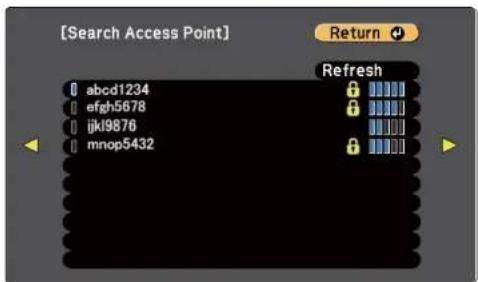
text_image
[Search Access Point] abcd1234 efgh5678 ijkl9876 mnop5432 Return + Refresh| Submenu Function | |
| Refresh | Searches for the access point again. |
| Indicates an already set access point. | |
Submenu Function

Indicates the access points where security is set.
If you select an access point where security has not been set, the Wireless LAN menu is displayed.
If you select an access point where security has been set, the Security menu is displayed. Select a type of security according to the security settings for the access point.
Wired LAN menu

text_image
Basic Wireless LAN Wired LAN Notifications Others Reset Complete IP Settings IP Address Display Off IPv6 Settings Return [Esc] /[●]:Return [◆]:SelectSubmenu Function
IP Settings
You can make settings related to the following addresses.
DHCP: Set to On to configure the network using DHCP. If this is set to On, you cannot set any more addresses.
IP Address: Enter the IP address assigned to the projector. You can enter a number from 0 to 255 in each field of the address. However, the following IP addresses cannot be used.
0.0.0.0, 127.x.x.x, 224.0.0.0 to 255.255.255.255 (where x is a number from 0 to 255)
Subnet Mask: Enter the projector's subnet mask. You can enter a number from 0 to 255 in each field of the address. However, the following subnet masks cannot be used.
0.0.0.0, 255.255.255.255
Gateway Address: Enter the IP address for the gateway for the projector. You can enter a number from 0 to 255 in each field of the address. However, the following Gateway Address cannot be used.
0.0.0.0, 127.x.x.x, 224.0.0.0 to 255.255.255.255 (where x is a number from 0 to 255)
| Submenu Function | |
| IP Address Display | To prevent the IP address from being displayed on the LAN Standby screen, set this to Off. |
| IPv6 Settings | Perform settings to use the IPv6 protocols. The following functions support IPv6 protocols.- Epson Web Control- PJLinkWhen setting the IPv6 address manually, make settings in Advanced from Epson Web Control."Changing Settings Using a Web Browser (Epson Web Control)" p.215IPv6: Set this to On when using IPv6 protocols. Make sure one link local address is set when using IPv6. This is composed of the interface ID created from fe80:: and the projector's MAC address.Auto Configuration: Set this to On to automatically acquire an IPv6 address from RA (Router Advertisement). The address is composed as shown below.Stateless Address (0 to 6): Created automatically by combining the prefix acquired from the RA (Router Advertisement) and the interface ID created from the projector's MAC address.Stateful Address (0 to 1): Created automatically from the DHCP server using DHCPv6.Use Temporary Address: Set this to On to temporarily validate the IPv6 address (0 to 1) when Auto Configuration is On. The following functions support IPv6 protocols.- Epson Web Control- PJLinkWhen setting the IPv6 address manually, make settings in Advanced from Epson Web Control."Changing Settings Using a Web Browser (Epson Web Control)" p.215IPv6: Set this to On when using IPv6 protocols. Make sure one link local address is set when using IPv6. This is composed of the interface ID created from fe80:: and the projector's MAC address.Auto Configuration: Set this to On to automatically acquire an IPv6 address from RA (Router Advertisement). The address is composed as shown below.Stateless Address (0 to 6): Created automatically by combining the prefix acquired from the RA (Router Advertisement) and the interface ID created from the projector's MAC address.Stateful Address (0 to 1): Created automatically from the DHCP server using DHCPv6.Use Temporary Address: Set this to On to temporarily validate the IPv6 address (0 to 1) when Auto Configuration is On. |
Notifications menu
When this is set, you receive an email notification if a problem or warning occurs in the projector.
"Reading error notification mail" p.225

text_image
Basic Wireless LAN Wired LAN Notifications Others Reset Complete Mail Notification Off SMTP Server 0. 0. 0. 0 Port Number 0 From Address 1 Setting Address 2 Setting Address 3 Setting SNMP Off Trap IP Address 1 0. 0. 0. 0 Trap IP Address 2 0. 0. 0. 0 Community Name PJLink Notification Off Notified IP Address 0. 0. 0. 0 Return| Submenu Function | |
| Mail Notification | Set to On to send an email to the preset addresses when a problem or warning occurs with a projector. |
| SMTP Server | You can input the IP Address for the SMTP server for the projector.You can enter a number from 0 to 255 in each field of the address. However, the following IP addresses cannot be used.L27.x.x.x,224.0.0.0 to 255.255.255.255 (where x is a number from 0 to 255) |
| Port Number | You can input the port number for the SMTP server. The default value is 25. You can input numbers between 1 to 65535. |
| From | Enter the email address of the sender. You can enter up to 64 single-byte alphanumeric characters. You can enter up to 32 characters on the Configuration menu. When entering more than 32 characters, use your Web browser to enter the text. (" ( ) , : ; < > | \ ] and spaces cannot be used.)● "Changing Settings Using a Web Browser (Epson Web Control)" p.215 |
| Address 1 Setting/ Address 2 Setting/ Address 3 Setting | Set the destination email addresses for the notification email, and the notification content. You can register up to three destinations. You can enter up to 64 single-byte alphanumeric characters. You can enter up to 32 characters on the Configuration menu. When entering more than 32 characters, use your Web browser to enter the text. (" ( ), :; < > [ \ ] and spaces cannot be used.)● "Changing Settings Using a Web Browser (Epson Web Control)" p.215 |
| SNMP | Set to On to monitor the projector using SNMP. To monitor the projector, you need to install the SNMP manager program on your computer. SNMP should be managed by a network administrator. The default value is Off. |
| Trap IP Address 1/ Trap IP Address 2 | You can register up to two IP addresses for the SNMP trap notification destination.You can enter a number from 0 to 255 in each field of the address. However, the following IP addresses cannot be used.127.x.x.x, 224.0.0.0 to 255.255.255.255 (where x is a number from 0 to 255) |
| Community Name | Set the community name of SNMP. You can enter up to 32 single-byte alphanumeric characters. (Spaces and symbols cannot be used.) |
| PJLink Notification | Set this to On to use the PJLink notification function. |
| Notified IP Address | Enter the IP address of the computer to which you want to send notifications of the projector's operating status using the PJLink notification function.You can enter a number from 0 to 255 in each field of the address. However, the following IP addresses cannot be used.127.x.x.x, 224.0.0.0 to 255.255.255.255 (where x is a number from 0 to 255) |
Others menu

text_image
Basic Wireless LAN Wired LAN Notifications Others Reset Complete Secure HTTP Web Server Cert. Priority Gateway AMX Device Discovery Crestron Connected Message Broadcasting Return Off Wired LAN Off Off Off [Esc] / [◆]: Return [◆]: Select| Submenu Function | |
| Secure HTTP | To strengthen security, communication between the projector and computer in Epson Web Control is encrypted. When setting security with Epson Web Control, we recommend setting this to On. |
| Web Server Cert. | Imports the Web server certificate used in Secure HTTP. |
| Priority Gateway | For the priority gateway, select either Wired or Wireless. |
| AMX Device Discovery | When you want to allow the projector to be detected by AMX Device Discovery, set this to On. Set this to Off if you are not connected to an environment controlled by a controller from AMX or AMX Device Discovery. |
| Crestron Connected | Set this to On only when monitoring or controlling the projector over the network using Crestron Connected®. Otherwise, set this to Off."About Crestron Connected®" p.228Changes in projector settings take effect upon restarting.When this is set to On, you cannot use the Message Broadcasting feature in Epson Projector Management. |
| Message Broadcasting | Set this to On to receive information sent by the Message Broadcasting feature in the Epson Projector Management software.Download software and User's Guides from the following Web site.http://www.epson.com |
Reset menu
Resets all of the network settings.

text_image
Reset network settings. Basic Wireless LAN Wired LAN Notifications Others Reset Complete [◆]:Select [●]:Enter| Submenu Function | |
| Reset network settings. | To reset all of the Network settings, select Yes. |
Info Menu (Display Only)
Lets you check the status of the image signals being projected and the status of the projector. Items that can be displayed vary depending on the source currently being projected.

text_image
Image Signal Settings Extended Network Info Reset Projector Info Light Source Info Version Status Information Temp Warning Info Power On/Off History Return [Esc] /[●]:Return [◆]:Select [Menu]:Exit| Submenu Function | ||
| Projector Info O | Operation Hours* | Displays the operation time after turning on the projector. |
| Source | You can display the source name for the connected equipment currently being projected. | |
| Input Signal | You can display the content of Input Signal set in the Signal menu according to the source. | |
| Resolution | You can display the resolution. | |
| Refresh Rate | You can display the Refresh Rate. | |
| Submenu Function | ||
| Sync Info | You can display the image signal information.This information may be needed if service is required. | |
| Status | This is information about errors that have occurred on the projector.This information may be needed if service is required. | |
| Serial Number | Displays the projector's serial number. | |
| Lens Type | Displays the model number of your lens. | |
| Event ID | When problems occur when the projector and computer are connected through the network, information on the problem is displayed using an Event ID. See the following page for information on interpreting the Event ID."About Event ID" p.201 | |
| HDBaseT Signal Level | Displays the level for the image signal being input from the HDBaseT port. When this is displayed in yellow, the strength of the signal level is reduced. We recommend the following signal levels.•1080p: 16dB or more•4K: 18dB or more | |
| Light Source Info | Light Source Hours | Displays the operating time for the light source according to the light source mode. |
| Estimated Remains | When Constant Brightness is set to On, this displays the amount of time for which the brightness of the light source can be maintained. | |
| Version Main | Video2SubSub2HDMIHDBaseTHDBaseT2 | Displays the projector's firmware version information. |
| Status Information | Displays the projector's status."Reading the Status Display" p.182 | |
| Temp Warning Info | Displays a high temperature warning. When you selectDetailwhen a Warning or Error is displayed, you can check detailed logs for before and after the error was detected. | |
| Power On/Off History | Displays the power on/off logs. | |
* The cumulative use time is displayed as "0H" for the first 10 hours. 10 hours and above is displayed as "10H", "11H", and so on.
Reset Menu

text_image
Image Signal Settings Extended Network Info Reset Return Reset All Memories Refresh Mode Light Source Calibration Reset All Config Reset All (Factory Default) Reset [Esc] / [◆]: Return [◆]: Select [Menu]: Exit| Submenu Function | |
| Reset All Memories | Resets all names and settings saved in Memory, Lens Position, and Geometry Correction.➤ "Memory Function" p.110 |
| Refresh Mode | Make settings related to the Refresh Mode.Timer: Select when to run Refresh Mode.Messages: Select whether or not to display messages during refresh operations.Start: Removes any afterimages (screen burn-in) that remain in the projected image. The projector turns off once the set time has elapsed. When you press any button on the control panel or remote control, a message is displayed asking if you want to continue using Refresh Mode. |
| Light Source Calibration | Make settings related to Light Source Calibration. When performing Light Source Calibration, the difference between the white balance and the brightness level for the light source is corrected. We recommend running this function periodically.●Run Now: Starts Light Source Calibration.This cannot be started in the following cases.- Within 20 minutes of turning on the projector.- If the surrounding temperature gets too high, and the brightness has been automatically dimmed.● Run Periodically: When this is set to On, Light Source Calibration is performed every 100 hours of use. When Off is selected to maintain the projected image that has been adjusted using Multi-Projection, perform corrections using Run Now or set the scheduling function to perform Light Source Calibration periodically.● Schedule Settings: Displays the schedule settings screen. Set Light Source Calibration to run periodically.● Last Run: Displays the last date and time Light Source Calibration was performed. |
| Reset All Config | You can reset all items in the Configuration menu to their default settings.The following items are not reset to their defaults: Input Signal, EDID, Memory, Content Playback, User's Logo, all items for Network menus, Language, Date & Time, Panel Alignment, Color Uniformity, Lens Calibration, Color Matching, Light Source Info, and Operation Hours. |
| Reset All (Factory Default) | Resets all of the projector's settings. However, Date & Time, Operation Hours, Light Source Info, Password Protection items and their passwords are not reset. You need to enter a password to perform a reset. The default password is set to "0000". Change this to your own desired password. |
Once the Configuration menu content has been set for one projector, you can use it to perform batch setup for multiple projectors (batch setup function). The batch setup function is only for projectors with the same model number.
Use one of the following methods.
- Setup using a USB flash drive.
- Setup by connecting the computer and projector with a USB cable.
- Set through Epson Projector Management.
This manual explains the USB flash drive and the USB cable methods.

- The content for Light Source Info and Status Information from the Info menu is not reflected by the batch setup function.
- Perform batch setup before adjusting the projected image. Adjustment values for the projected image, such as Geometry Correction are reflected by the batch setup function. If batch setup is performed after adjusting the projected image, the adjustments you made may change.
- By using the batch setup function, the registered User's Logo is set for the other projectors. Do not register confidential information and so on as the User's Logo.
- If you do not want to copy the following settings, set Batch Setup Range to Limited.
- EDID from the Signal menu
- Network menu (except for the Notifications menu and the Others menu)
Extended - Operation - Advanced - Batch Setup Range p.146
- Items for which Password Protection is set are not copied.

Caution
Performing batch setup is the customers responsibility. If batch setup fails due to a power failure, communication error, and so on, the customer is responsible for any repair costs incurred.
Setup Using a USB Flash Drive
This section explains how to perform batch setup using a USB flash drive.

- Use a FAT format USB flash drive.
- The batch setup function cannot be used by USB flash drives that incorporate security functions. Use a USB flash drive that does not incorporate security functions.
•The batch setup function cannot be used by USB card readers or USB hard disks.
Saving settings to the USB flash drive
1 Disconnect the power cord from the projector, and check that all of the projector's indicators have turned off.
2 Connect a USB flash drive to the projector's USB-A port (the wireless LAN module installation section).
"Installing the Wireless LAN Unit" p.54

natural_image
Diagram of a refrigerator interior with a blue plastic component inserted, showing no text or symbols
- Connect the USB flash drive directly to the projector. If the USB flash drive is connected to the projector through a USB hub, the settings may not be saved correctly.
- Connect an empty USB flash drive. If the USB flash drive contains data other than the batch setup file, the settings may not be saved correctly.
- If you have saved a batch setup file from another projector to the USB flash drive, delete the file or change the file name. The batch setup function cannot overwrite a batch setup file.
- The file name for the batch setup file is PJCONFDATA.bin. If you need to change the file name, add text after PJCONFDATA. If you change the file name in any other way, the projector may not be able to recognize the file correctly.
- You can only use single-byte characters for the file name

While holding down the Esc button on the remote control or the control panel, connect the power cord to the projector.

text_image
Menu Enter +Batch Setup

When the projector's indicators turn on as follows, release the Esc button.
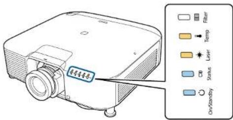
text_image
投影器 On/Standby Filter Temp Laser StatusPower supply Status Laser Temp
Blue - On Blue - On Orange - On Orange - On
When all of the indicators start flashing, the batch setup file is being written.

Caution
- Do not disconnect the power cord from the projector while the file is being written. If the power cord is disconnected, the projector may not start correctly.
- Do not disconnect the USB flash drive from the projector while the file is being written. If the USB flash drive is disconnected, the projector may not start correctly.
When writing completes normally, the projector enters standby status.

text_image
光盘参考器 On/Standby Fiber Temp Laser StatusPower
Blue - On
When the projector is in standby status, remove the USB flash drive.
Reflecting saved settings to other projectors
1 Disconnect the power cord from the projector, and check that all of the projector's indicators have turned off.
2 Connect the USB flash drive on which the settings are saved to the projector's USB-A port (the wireless LAN module installation section).

natural_image
Diagram of a refrigerator interior with a blue plastic component inserted, showing no text or symbols
- When the USB flash drive contains 1 to 3 types of batch setup files, the file is reflected to the projector with the same model number. If there are multiple files for a projector with the same model number, the settings may not be reflected correctly.
- When there are four or more types of batch setup files on the USB flash drive, the settings may not be reflected correctly.
- Do not store any data except for the batch setup file on the USB flash drive. If the USB flash drive contains data other than the batch setup file, the settings may not be reflected correctly.
3 While holding down the Menu on the remote control or the control panel, connect the power cord to the projector.

text_image
Menu Enter i +When the projector's indicators turn on as follows, release the Menu button.
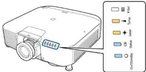
text_image
Filter Spring Laser Status On/StandbyPower supply Status Laser Temp
Blue - On Blue - On Orange - On Orange - On
The indicators remain on for about 75 seconds.
When all of the indicators start flashing, the settings are being written.

Caution
- Do not disconnect the power cord from the projector while the settings are being written. If the power cord is disconnected, the projector may not start correctly.
- Do not disconnect the USB flash drive from the projector while the settings are being written. If the USB flash drive is disconnected, the projector may not start correctly.
4 When writing completes normally, the projector enters standby status.

text_image
Fiber Temp Laser Status OvSandyPower Blue - On
When the projector is in standby status, remove the USB flash drive.
Setup by Connecting the Computer and Projector with a USB Cable

The following operating systems support the batch setup function
•Windows Vista or later
•Mac OS X 10.7.x or later
Saving settings to a computer
1 Disconnect the power cord from the projector, and check that all of the projector's indicators have turned off.
2 Connect the computer's USB port to the projector's Service port with a USB cable.
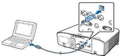
natural_image
Diagram showing a laptop connected to an oscilloscope with a device and signal output (no text or symbols present)3 While holding down the Esc button on the remote control or the control panel, connect the power cord to the projector.

text_image
Menu Enter +Batch Setup

When the projector's indicators turn on as follows, release the Esc button.
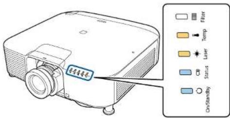
text_image
Filter Temp Laser Status OloStandbyPower supply Status Laser Temp
Blue - On Blue - On Orange - On Orange - On
The projector is recognized as a removable disk by the computer.
4 Open the removable disk, and save the batch setup file (PJCONFDATA.bin) to the computer.

If you need to change the name of the batch setup file, add text after PJCONFDATA. If you change the file name, the projector may not be able to recognize the file correctly.
5 Perform "Remove USB device" on your computer, and then disconnect the USB cable.

When using Mac, perform "Remove EPSON_PJ".
The projector enters standby status.
Reflecting saved settings to other projectors
1 Disconnect the power cord from the projector, and check that all of the projector's indicators have turned off.
2 Connect the computer's USB port to the projector's Service port with a USB cable.

text_image
Diagram showing a laptop connected to an oscilloscope with an attached device, illustrating the connection and display setup.Batch Setup

3 While holding down the Menu on the remote control or the control panel, connect the power cord to the projector.

text_image
Diagram showing a hand gesture with 'Menu' and 'Esc' labels, a plus sign, and an attached USB port with blue arrow indicating connection.When the projector's indicators turn on as follows, release the Menu button.

text_image
Filter Temp Laser Status On/StandbyPower supply Status Laser Temp
Blue - On Blue - On Orange - On Orange - On
The projector is recognized as a removable disk by the computer.
4 Copy the batch setup file (PJCONFDATA.bin) that you saved to your computer to the top level folder of the removable disk.

Do not copy any files or folders other than the batch setup file to the removable disk.
5 Perform "Remove USB device" on your computer, and then disconnect the USB cable.

When using Mac, perform "Remove EPSON_PJ".
When all of the indicators start flashing, the settings are being written.

Caution
Do not disconnect the power cord from the projector while the settings are being written. If the power cord is disconnected, the projector may not start correctly.
When writing completes normally, the projector enters standby status.
When Setup Fails
The Indicators notify you if an error occurs. Check the status of the indicators.
| Status of the Indicators Remedy | |
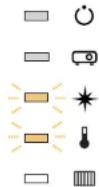 Laser: Orange - flashing fastTemp: Orange - flashing fast Laser: Orange - flashing fastTemp: Orange - flashing fast | The batch setup file may be corrupt, or the USB flash drive may not be connected correctly.Disconnect the USB flash drive, unplug and then plug in the projector's power cord, and then try again. |
 Power: Blue - flashing fastStatus: Blue - flashing fastLaser: Orange - flashing fastTemp: Orange - flashing fast Power: Blue - flashing fastStatus: Blue - flashing fastLaser: Orange - flashing fastTemp: Orange - flashing fast | Writing the settings may have failed and an error may have occurred in the projector's firmware.Stop using the projector, remove the power plug from the electrical outlet, and contact your local dealer or the nearest address provided in the Epson Projector Contact List.Epson Projector Contact List |

Troubleshooting
This chapter explains how to identify problems and what to do if a problem is found.
Using the Help

If a problem occurs with the projector, you can display the Help screen to assist you. You can also set the projector to an appropriate state by answering the questions.
1 Press the [ ] button.
The Home screen is displayed.
![EPSON EB-L1065UNL - Press the [ ] button. - 1](/content/2026/06/1211104/images/e9092354b8c3fbdf33b93b1c32254680e1b74dc8435bbf050c2eab15fe9d6264.jpg)
text_image
Remote control 4 5 6 7 8 9 ID 0 Num ID On Off Home2 Select Help, and then press the [] button.
![EPSON EB-L1065UNL - Select Help, and then press the [] button. - 1](/content/2026/06/1211104/images/dfd8d78c2bca208d71ea52d58318c81066303ac2828753da76351241ec373906.jpg)
text_image
EPSON Sources - Searching at Source... HDNI HDBase T DVI-0 Computer BNC USB LAN Username Function: Color Mode Light Source Mode Image Enhancement Frame Interpolation Menu Help Content Playback : On Projector Name: xxxxxxxxx Keyword: xxxxx SSD: xxxxxxxxx-xxxxxxxxxxxxxxxxx IP: xxxxxxxxx IP: xxxxxxxxx.xx Connection Guide Submit the source. [Home] ExitThe Help screen is displayed.
![EPSON EB-L1065UNL - Select Help, and then press the [] button. - 2](/content/2026/06/1211104/images/1b9bfa0932b9d2b7b53c972891ccb4177828605b22dca8edcbd2c89315886ece.jpg)
text_image
[Help] The image is small. The image is distorted. The color tone is unusual. There is no audio or it is too low.3 Select a menu item.

4 Confirm the selection.

Questions and solutions are displayed as shown on the screen below. Press the Menu button to exit Help.
The image is small.
Is zoom set to minimum?
- Press the [Zoom] button to change the size of the image.
Is the projector too close to the screen? Move the projector away from the screen.

See the following if the Help function does not provide a solution to the problem.
"Reading the Indicators" p.175
This projector has the following five indicators to indicate the projector's status.

text_image
① On/Standby ② Status ③ Laser ④ Temp ⑤ Filter① Power indicator
Indicates the projector's status.
② Status indicator
Indicates the projector's status.
③ Laser indicator
Indicates the light source status.
4 Temp indicator
Indicates the internal temperature status. This is normally turned off.
⑤ Filter indicator
Indicates the air filter status. This is normally turned off.
The following indicator status are used during regular operation.
"Status varies" indicates that the indicators turn on, off, or flash depending on the status of the projector.
| Indicator Projector's Sta- | tus | Explanation | ||||
| Power supply | Status Laser Temp | Filter | ||||
| Blue - On | Off Off Off | Off | Off | Off | Standby condition | Power is being supplied to the projector. In this status, you can start projecting by pressing the [1] button on the remote control or control panel.(Sometimes, when the power cord is unplugged, the power indicator remains lit for a short period, but this is not a fault.) |
| Network monitor-ing status | The projector is being monitored and controlled over a network (when Standby Mode is set to Communication On).If the power cord is disconnected and then reconnected in this status, the power indicator flashes blue. | |||||
| Blue - On | Blue - Flashing | Status varies | Off Off | Off | Warm-up status | This is the status immediately after turning on the projector. Warm-up takes approximately 30 seconds after the light source turns on.The [O] button is disabled during warm-up. |
| Blue - On | Blue - On Status varies | Off Off | Off Off | 0 | Projecting The projector is projecting. | |
| Blue - On | Blue - Flashing | Off Off | Off | 0 | Cool down status | This is the status immediately after turning off the power. In this status, all buttons are disabled. |
| Blue - Flashing | Off Off | Off Off | 0 | 0 | Preparing Network monitoring | Preparing to monitor and control this projector over a network.During network monitoring preparation, all button operations are disabled. |
| Blue - On | Blue - On | Blue - Flashing | Off Off | 0 | A/V Mute activated | A/V Mute is active. |
| Status varies | Blue - Flashing | Orange - Flashing | Status varies | Status varies | Refresh Mode activated | Refresh Mode is active.Reset - Refresh Mode p.162 |
When an error has occurred in the projector, the error status is indicated by the indicator's color and combination of flashing or lit.
Refer to the following table to see what the indicators mean and how to remedy problems that they indicate.
| Indicator Cause Remedy or Status | ||||||
| Power supply | Status Laser Temp | Filter | ||||
| Off | [08T5]Blue - Flashing |  Orange - Flashing Orange - Flashing | [26T6]Off Off | Off | Internal Error | Stop using the projector, remove the power plug from the electrical outlet, and contact your local dealer or the nearest address provided in the Epson Projector Contact List.Epson Projector Contact List |
| Off | [DTAB]Blue - Flashing | Off |  Orange - Flashing Orange - Flashing | Off | Fan ErrorSensor Error | Stop using the projector, remove the power plug from the electrical outlet, and contact your local dealer or the nearest address provided in the Epson Projector Contact List.Epson Projector Contact List |
| Off |  Blue - Flashing Blue - Flashing | Off | Orange - On | Off | High Temp Error(Overheating) | The light source turns off automatically and projection stops. Wait for about five minutes. After about five minutes, the projector switches to standby mode, so check the following three points.Check that the air filter, air exhaust vent, and air intake vent are clear, and that the projector is not positioned against a wall.Check if the temperature around the air intake is too high.If the air filter are clogged, remove the power cord from the electrical outlet, and then clean or replace them."Cleaning the Air Filter and Air Intake Vent" p.204"Replacing the Air Filter" p.208If the error continues after checking the points above, stop using the projector, remove the power plug from the electrical outlet, and contact your local dealer or the nearest address provided in the Epson Projector Contact List.Epson Projector Contact List |
| When using at an altitude of 1500 m or more, set High Altitude Mode to On.Extended - Operation - High Altitude Mode p.146 | ||||||
| Off | Blue - Flashing | Orange - On | Off Off | Off | Laser Error Retardation Plate Error | Stop using the projector, remove the power plug from the electrical outlet, and contact your local dealer or the nearest address provided in the Epson Projector Contact List.Epson Projector Contact List |
| Off | Blue - Flashing | Off Off | Off Off | Orange - On | Filter Airflow Error | Check the following two points.Check that the air filter and air exhaust vents are clear, and that the projector is not positioned against a wall.If the air filter is clogged, turn off the power, remove the power cord from the electrical outlet, and then clean or replace them."Cleaning the Air Filter and Air Intake Vent" p.204"Replacing the Air Filter" p.208After checking, connect the power cord to the electrical outlet.If the error continues after checking the points above, stop using the projector, remove the power plug from the electrical outlet, and contact your local dealer or the nearest address provided in the Epson Projector Contact List.Epson Projector Contact List |
| Off | Blue - Flashing | Orange - On | Orange - On | Off | Lens Shift Error | Stop using the projector, remove the power plug from the electrical outlet, and contact your local dealer or the nearest address provided in the Epson Projector Contact List.Epson Projector Contact List |
| Off[22CD]Blue - Flashing | Blue - FlashingStatus varies | Orange - On[2860]Status varies | Orange - On[7D0Z]Orange - Flashing | Off[03KO]Status varies | Lens Error No LensHigh Temp Warning | Install the lens unit. If the lens unit is already installed, remove it and then reinstall it. If the error continues after checking the points above, stop using the projector, remove the power plug from the electrical outlet, and contact your local dealer or the nearest address provided in the Epson Projector Contact List.Epson Projector Contact ListThis is not an error. However, if the temperature rises too high again, projection stops automatically. Check the following three points.Check that the air filter, air exhaust vent, and air intake vent are clear, and that the projector is not positioned against a wall.Check if the temperature around the air intake is too high.If the air filter is clogged, turn off the power, remove the power cord from the electrical outlet, and then clean or replace them."Cleaning the Air Filter and Air Intake Vent" p.204"Replacing the Air Filter" p.208 |
| - [24XA]Blue - Flashing | Status varies |  Orange - Flashing Orange - Flashing |  Status varies Status varies | [CKBD]Status varies | Laser Warning | Stop using the projector, remove the power plug from the electrical outlet, and contact your local dealer or the nearest address provided in the Epson Projector Contact List.Epson Projector Contact List |
| [6460]Blue - Flashing[120] | Status variesStatus varies |  Orange - FlashingStatus varies Orange - FlashingStatus varies |  Status variesStatus varies Status variesStatus varies |  Status variesOrange - On Status variesOrange - On | Lens Warning An unsupported lens is attached. Use a supported lens."Optional Accessories and Consumables" p.233Low Air Flow | This is not an error. However, projection stops automatically if the airflow falls any further.The message "The air filter is clogged. Clean or replace the air filter." is displayed. Check the following two points.Check that the air filter and air exhaust vents are clear, and that the projector is not positioned against a wall.If the air filter is clogged, turn off the power, remove the power cord from the electrical outlet, and then clean or replace them."Cleaning the Air Filter and Air Intake Vent" p.204"Replacing the Air Filter" p.208If the error continues after checking the points above, stop using the projector, remove the power plug from the electrical outlet, and contact your local dealer or the nearest address provided in the Epson Projector Contact List.Epson Projector Contact List |
| [120] | Status varies | Status varies | Status varies | Orange - Flashing | Air Filter Notice | "Time to clean the air filter. Clean or replace the air filter." is displayed.Turn off the projector's power, unplug the power cord from the electrical outlet, and then clean the air filter."Cleaning the Air Filter and Air Intake Vent" p.204The indicators or messages regarding air filter notice are displayed only when Air Filter Notice is set to On in the Configuration menu.Extended - Display - Air Filter Notice p.146 |
| [120] | Status varies | Status varies | Status varies | Status varics | ||
| [120] | Status varies | Orange - Flashing | Status varies | Status varics | Constant Brightness End | Ends the Constant Brightness mode in Brightness Settings."Setting the Brightness" p.77 |


text_image
dir Pow supl Blu Flash Stat vari Stat vari


- See the following if the projector is not operating properly, even though the indicators are all showing normal.
"Problem Solving" p.190 - If the indicators are in a state not shown in this table, stop using the projector, remove the power plug from the electrical outlet, and contact your local dealer or the nearest address provided in the Epson Projector Contact List.
Epson Projector Contact List
Reading the Status Display

You can display the operating status of the projector on the projected image. You can check the detailed status of the projector by using button operations.
1 Press the [] button while projecting.

text_image
Remote control Control panel Geometry Memory User2 User3 2 3 4 5 6 A/V Mate Lens2 Select Status Information, and then press the [←] button.

text_image
Image Signal Settings Extended Network Info Reset Return Projector Info Light Source Info Version Status Information Temp Warning Info Power On/Off History [Esc] :Return [◆]:Select [●]:Enter [Menu]:Exit
text_image
You can also operate from the Configuration menu. Info - Status Information p.1613 Use the [◀][▶] buttons or the [▲][▼] buttons to select a category.

text_image
[Status Information] 1/7 Return [Status Information] System Source Computer On-ScreenDisplay On A/V Note On Intake Air Temp Internal Temp LV L Laser Status On Info Reset [Esc] / [●]:Return [◀●]:Select [Menu]:ExitEach display category contains the following information.
Status Information : Operating status of the projector
Source : Input signal information
Signal Information : Input digital signal information
Network Wired: Wired LAN settings
Network Wireless : Wireless LAN settings
Maintenance : Operating time for the projector and light source
Version : Projector's firmware version
Explanations of the Display Content
| Category Item Status Display Explanation | |||
| Status Information | System | Displays the projector's status. See the following for more information on how to remedy the errors and warnings. "Reading the Indicators" p.175 | |
| OK The projector is | in normal status. | ||
| Warm-Up The projector | is warming up. | ||
| Standby The projector is | in standby status. | ||
| Cool Down The projector | is in cool down status. | ||
| Temp Error A high temp error has occurred. | |||
| Fan Error A fan error | has occurred. | ||
| Sensor Error A sensor error has occurred. | |||
| Power Error A power error (Ballast) has occurred. | |||
| Internal Error | An internal error has occurred. | ||
| Airflow Error | A filter airflow error has occurred. | ||
| Temp Warning | A high temp warning has occurred. | ||
| Internal Warning | A warning about the internal system has occurred. | ||
| Airflow Decline | A low air flow error has occurred. | ||
| Power Warning | A power warning (Ballast) has occurred. | ||
| Clean Filter | An air filter notice has occurred. | ||
| Lens Error | A lens error has occurred. | ||
| Laser Error | A laser error has occurred. | ||
| Laser Warning | A laser warning has occurred. | ||
| Temp Error FE | A laser error has occurred because the laser temperature is too high. | ||
| Temp Warning FE | A laser warning has occurred because the laser temperature is too high. | ||
| Status Information | Source | HDMI | Displays the source name for the connected equipment currently being projected. |
| HDBascT | |||
| DVI-D | |||
| Computer | |||
| BNC | |||
| USB | |||
| LAN | |||
| On-Screen Display | On | Displays the settings for the On-Screen Display. When set to Off, the menus or messages are not displayed on the projected images. | |
| Off | |||
| A/V Mute On Displays | the operating status of A/V mute. | ||
| Off | |||
| Intake Air Temp - Displays the air intake temperature. | |||
| Internal Temp Lv - Displays the projector's internal temperature. | |||
| Laser Status | On Displays the operating status of the light source. | ||
| Off | |||
| Source | Source | HDMI | Displays the source name for the connected equipment currently being projected. |
| HDBascT | |||
| DVI-D | |||
| Computer | |||
| BNC | |||
| USB | |||
| LAN | |||
| Resolution - Displays the resolution of the current input signal. | |||
| Source Color Space RGB | Displays the color space | of the current input signal. | |
| YCbCr | |||
| YPbPr | |||
| H-Frequency - Displays | the horizontal frequency | of the current input signal. | |
| V-Frequency - Displays | the vertical frequency of | the current input signal. | |
| Sync Polarity H:Posi / V | V:Posi Displays the Sync | polarity. | |
| II:Posi / V:Nega | |||
| II:Nega / V:Posi | |||
| H:Nega / V:Nega | |||
| Sync Mode Composite Sync | Displays the | sync type. | |
| Separate Sync | |||
| Sync On Green | |||
| Detected Mode | - | Displays the discriminant resolution of the current input signal. | |
| Transport | Interlace | Displays the scanning method. | |
| Progressive | |||
| Video Range | Auto(Limited) | Displays the video level of the projector. | |
| Auto(Full) | |||
| Limited(16-235) | |||
| Full(0-255) | |||

Items displayed for source vary depending on the model being used and the image signal and source being projected.
| Category Item Status Display Explanation | |||
| Signal Information 5V Detect Detected Displays the detection results of 5V signals. | |||
| Not Detect | |||
| TMDS Clock - Displays the TMDS frequency of the current input signal. | |||
| H-Frequency - Displays the horizontal frequency of the current input signal. | |||
| V-Frequency - Displays the vertical frequency of the current input signal. | |||
| DetChg 5CFHMP123 - Displays the factors of signal changes. | |||
| Stable Time - Displays the operating time since the input source is determined. | |||
| IIDCP Status | Non-IIDCP Displays the IIDCP status. | ||
| Passed | |||
| Failed | |||
| HDCP Ri | - | ||
| HDCP AKSV | - | ||
| HDCP An | - | ||
| HDCP Ver | - Displays the HDCP version. | ||
| AVI VIC | - Displays the VIC information (AVI) of the current input signal. | ||
| AVI Checksum | OK Displays the checksum result for AVI. | ||
| NG | |||
| AVI Sampling Str | RGB4:4:4 Displays color sampling for AVI. | ||
| YCbCr4:4:4 | |||
| YCbCr4:2:2 | |||
| YCbCr4:2:0 | |||
| Signal Mode HDMI | Displays the signal mode. | ||
| DVI | |||
| EDID Mode | - Displays the EDID mode. | ||
| HDBascT Level | - You can display the image signal information from the HDBascT port. | ||
Reading the Status Display


Items displayed for Signal Information vary depending on the model being used and the image signal and source being projected.
| Category Item Status Display Explanation | ||||
| Network Wired | Projector Name | - | Displays the projector name used to identify the projector when connected to a network. | |
| Connection Mode HDBaseT Displays the connection path for LAN. | ||||
| LAN | ||||
| DHCP On Displays the | DHCP settings. | |||
| Off | ||||
| IP Display On Displays | the IP address display settings. | |||
| Off | ||||
| IP Address - Displays the IP address. | ||||
| MAC Address | - Displays the MAC address. | |||
| Network Wireless | Projector Name | - | Displays the projector name used to identify the projector when connected to a network. | |
| Connection Mode | Quick | Displays the connection mode to use when connecting the projector and a computer over a wireless LAN. | ||
| Advanced | ||||
| SSID Display | On Displays the SSID | display settings. | ||
| Off | ||||
| IP Display On Displays | the IP address display settings. | |||
| Off | ||||
| SSID | - Displays the SSID. | |||
| IP Address - Displays the IP address. | ||||
| DUCP On Displays the | DUCP settings. | |||
| Off | ||||
| MAC Address | - Displays the MAC address. | |||
| Security | No | Displays the security settings. | ||
| WPA2-PSK | ||||
| WPA/WPA2-PSK | ||||
| Antenna Level | LEVEL 0-5 | Displays the reception status for Wi-Fi. | ||
| Maintenance Operation Time - Displays the total operation time of the projector. | ||||
| Laser Op.Time | - | Displays the laser operating time for each setting in Light Source Mode. | ||
| Version Serial No. - Displays the projector's serial number. | ||||
If any of the following problems occur and the indicators do not offer a solution, refer to the pages given for each problem.
Problems Relating to Images
| No images appearProjection does not start, the projection area is completely black, or the projection area is completely blue. | p.191 |
| Moving images are not displayedVideos played back on a computer are black or no image is projected, or the video is not played back on the computer. | p.191 |
| Projection stops automatically | p.192 |
| The message "Not supported" is displayed | p.192 |
| “No Signal” is displayed | p.192 |
| Images are fuzzy, out of focus, or distorted | p.193 |
| Interference or distortion appear in images | p.193 |
| The image is truncated (large) or small, the aspect ratio is not suitable, or the image has been reversedOnly part of the image is displayed, the height and width ratios of the image are not correct, or the image may appear reversed from top to bottom or left to right. | p.194 |
| Image colors are not rightThe whole image appears purplish or greenish, images are black & white, or colors appear dull. | p.195 |
| Images appear dark p.195 |
Problems when Projection Starts
| • 'The projector does not turn on | p.196 |
Problems with Content Playback Mode
| Cannot play the playlist | p.197 |
Other Problems
| • There are afterimages (screen burn-in) in the projected image | p.197 |
| • No sound can be heard or the sound is faint | p.198 |
| • The remote control does not work | p.198 |
| • Nothing appears on the external monitor | p.199 |
| • I want to change the language for messages and menus | p.199 |
| • Email is not received even if a problem occurs in the projector | p.200 |
| • “The battery that saves your clock settings is running low.” is displayed | p.200 |
Problems Relating to Images
No images appear
| Check Remedy | |
| Did you press the [ ⏻ ] button on the remote control or control panel? | Press the [ Ⓑ button to turn on the power. |
| Are the indicators switched off? | The power cord is not connected correctly or power is not being supplied.Connect the projector's power cord correctly.Check that your electrical outlet or power source is functioning correctly. |
| Is A/V Mute active? Press the [A/V Mute] button to release A/V Mute. | "Hiding the Image and Sound Temporarily (A/V Mute)" p.102 |
| Are the Configuration menu settings correct? Reset all of the settings. | Reset - Reset All Config p.162 |
| Is the image to be projected completely black?(Only when projecting computer images) | Some input images, such as screen savers, may be completely black. |
| Is Windows Media Center displayed in full screen?(Only during network connection) | When Windows Media Center is displayed at full screen, you cannot project using a network connection. Reduce the screen size. |
| Is an application using the Windows DirectX function displayed?(Only during network connection) | Applications using the Windows DirectX function may not display images correctly. |
Moving images are not displayed
| Check Remedy | |
| Is the computer's image signal being output to the LCD and the monitor?(Only when projecting images from a laptop computer or a computer with a built-in LCD screen) | Change the image signal from the computer to external output only. Check your computer's documentation, or contact the computer's manufacturer. |
| Are the contents of the moving image you are trying to project copyright protected? | The projector may not be able to project copyright protected moving images that are being played back on a computer. For more details, see the user's guide supplied with the player. |
Projection stops automatically
| Check Remedy | |
| Is Sleep Mode set to On? | Press the [ ⏻ ] button to turn on the power. If you do not want to use Sleep Mode, change the setting to Off. ➕ Extended - Operation - Sleep Mode p.146 |
"Not supported" is displayed
| Check Remedy | |
| Do the image signal resolution and the refresh rate correspond to the mode?(Only when projecting computer images) | Refer to the computer's documentation for how to change the image signal resolution and the refresh rate output from the computer.■ "Supported Monitor Displays" p.274 |
"No Signal" is displayed
| Check Remedy | |
| Are the cables connected correctly? | Check that all the cables required for projection are securely connected.Check that no cables are disconnected and that there are no poor contacts in the cables. |
| Is the correct port selected? Change the image by pressing the [Search] button. | "Automatically Detecting Input Signals and Changing the Projected Image (Source Search)" p.61 |
| Is the power for the computer or video source turned on? Turn the power on for the equipment. | |
| Are the image signals being output to the projector?(Only when projecting images from a laptop computer or a computer with a built-in LCD screen) | If the image signals are only being output to the computer's LCD monitor or to the accessory monitor, you need to change the output to an external destination as well as the computer's own monitor. For some computer models, when the image signals are output externally, they no longer appear on the LCD monitor or accessory monitor.If the connection is made while the power of the projector or computer is already turned on, the Fn key (Function key) that changes the computer's image signal to external output may not work. Turn the power for the computer and the projector off and then back on again.Computer's documentation |
Images are fuzzy, out of focus, or distorted
| Check Remedy | |
| Is the focus adjusted correctly? | Make sure that at least 20 minutes has passed after the projection starts, and press the [Focus] button on the remote control to adjust the focus.■ "Correcting the Focus" p.38 |
| Is the projector at the correct distance? | Is it projecting outside of the recommended projection distance range?Setup within the recommended range.■ "Screen Size and Projection Distance" p.234 |
| I has condensation formed on the lens? | If the projector is suddenly taken from a cold environment to a warm environment, or if sudden ambient temperature changes occur, condensation may form on the surface of the lens, and this may cause the images to appear fuzzy. Set the projector up in the room about one hour before it is used. If condensation forms on the lens, turn the projector off and wait for the condensation to disappear. |
Interference or distortion appear in images
| Check Remedy | |
| Are the cables connected correctly? | Check that all the cables required for projection are securely connected.⇨ "Connecting Equipment" p.47 |
| Is an extension cable being used? | If an extension cable is used, electrical interference may affect the signals. |
| Is the correct resolution selected?(Only when projecting computer images) | Set the computer so that the signals being output are compatible with the projector.⇨ "Supported Monitor Displays" p.274⇨ Computer's documentation |
| Is the Sync./Tracking adjusted correctly?(Only when projecting computer images) | Press the [Auto] button on the Remote Control or the [ ↺ ] button on the Control panel to perform automatic adjustment. If the images are not adjusted correctly even after performing automatic adjustment, you can also make adjustments from the Configuration menu.⇨ Signal - 'Tracking, Sync. p.142 |
| Is the Resolution set to anything other than Auto?(Only when projecting on a split screen) | The image may be collapsed if the Resolution on the Configuration menu and the resolution of the projected image are not the same.If the image is collapsed, set the Resolution to Auto.⇨ Signal - Resolution p.142 |
The image is truncated (large) or small, the aspect is not suitable, or the image has been reversed
| Check Remedy | |
| Have theScreenbeen set correctly? | Make the appropriateScreenfor the screen being used.⇨ "Screen Settings" p.32 |
| Is the aspect adjusted correctly? | Press the [Aspect] button to select an aspect suitable for the input source.⇨ "Changing the Aspect Ratio of the Projected Image" p.80 |
| Is a wide panel computer image being projected?(Only when projecting computer images) | Change the setting according to the signal for the connected equipment.⇨ Signal - Resolution p.142 |
| Is the image still being enlarged by E-Zoom? | Press the [Esc] button on the remote control to cancel E-Zoom.⇨ "Enlarging Part of the Image (E-Zoom)" p.104 |
| IsScaleturned on? | SetScalcto Offon the configuration menu.⇨ Signal - Scale - Scaled p.142 |
| Is the display range restricted byBlanking? | Appropriately setBlankingin the configuration menu.⇨ Signal - Blanking p.142 |
| Is the image position adjusted correctly? | (Only when projecting analog RGB signals input from the Computer port)Press the [Auto] button on the remote control or the [←] button on the control panel to adjust the position.You can also adjust the position from the Configuration menu.⇨ Signal - Position p.142 |
| Is the computer set for dual display?(Only when projecting computer images) | If dual display is activated in theDisplay Propertiesof the computer’s Control Panel, only about half of the image on the computer screen is projected. To display the entire image on the computer screen, turn off the dual display setting.⇨ Computer video driver documentation |
| Is the correct resolution selected?(Only when projecting computer images) | Set the computer so that the signals being output are compatible with the projector.⇨ "Supported Monitor Displays" p.274⇨ Computer’s documentation |
| Is the image direction correct? | Make the correct settings inProjectionfrom the Configuration menu.⇨ "Installation Settings" p.31 |
Image colors are not right
| Check Remedy | |
| Do the input signal settings match the signals from the connected device? | Change the setting according to the signal for the connected equipment.■ Signal - Advanced - Input Signal p.142 |
| Is the image brightness adjusted correctly? | Adjust the Brightness setting from the Configuration menu.■ Image - Brightness p.140 |
| Are the cables connected correctly? | Check that all the cables required for projection are securely connected.Check that no cables are disconnected and that there are no poor contacts in the cables.■ "Connecting Equipment" p.47 |
| Is the Contrast adjusted correctly? | Adjust the Contrast setting from the Configuration menu.■ Image - Contrast p.140 |
| Is the color adjustment set correctly? | Adjust the Gamma or RGBCMY setting from the Configuration menu.■ Image - Advanced p.140■ "Adjusting the Image" p.81 |
| Are the color saturation and tint adjusted correctly? | Adjust the Color Saturation and Tint settings from the Configuration menu.■ Image - Color Saturation, Tint p.140 |
| Are you projecting from multiple projectors at the same time? | Make sure that Light Source Calibration from the Reset menu is set correctly for all of the projectors. If Light Source Calibration is only executed for some of the projectors, there may be differences in the White Balance or the Brightness Level between projectors.If there are still differences in the color, set Light Source Calibration to Off. |
Images appear dark
| Check Remedy | |
| Is the image brightness set correctly? | Check theBrightnessandBrightness Settingsvalues from the Configuration menu.➤ Image - Brightness p.140➤ Settings - Brightness Settings p.143 |
| Is the Contrast adjusted correctly? | Adjust theContrastsetting from the Configuration menu.➤ Image - Contrast p.140 |
| Is only one projector being used? Check if the following item is set to dark. | Extended - Multi-Projection- Brightness Settings p.146 |
Problems when Projection Starts
The projector does not turn on
| Check Remedy | |
| Did you press the [ ⏻ ] button on the remote control or control panel? | Press the [ ⏻ button to turn on the power. |
| Are the indicators switched off? | The power cord is not connected correctly or power is not being supplied.Disconnect and then reconnect the power cord.Check that your electrical outlet or power source is functioning correctly. |
| Do the indicators turn on and off when the power cord is touched? | There is probably a poor contact in the power cable, or the power cable may be defective. Reinsert the power cable. If this does not solve the problem, stop using the projector, disconnect the power cable from the electrical outlet, and contact your local dealer or the nearest address provided in the Epson Projector Contact List.Epson Projector Contact List |
| Is the Control Panel Lock set to Full Lock? | Press the [ ⏻ ] button on the remote control. If you do not want to use Control Panel Lock, change the setting to Off."Control Panel Lock" p.117 |
| Is the correct setting for the remote receiver selected? | Check the Remote Receiver from the Configuration menu.Settings - Remote Receiver p.143 |
| Was the power cord plugged back in or was the breaker turned on immediately after direct power off? | If the operation described in the column on the left is performed when Direct Power On is set to On, the power may not turn back on. Press the [ ⏻ ] button to turn on the power. |
| Is the [ID] switch on the remote control set to On? | When the switch is set to On, you can use the remote control to operate only a projector with a matching ID. Set the [ID] switch to Off."Setting the remote control ID" p.43 |
Problems with Content Playback Mode
Cannot play the playlist
| Check Remedy | |
| Is Content Playback set to On? | Set Content Playback to On, and then restart the projector. You can only play playlists on USB flash drives in Content Playback mode.Settings - Content Playback - Content Playback p.143 |
| Are there any playlists on the USB flash drive? | Make sure the USB flash drive contains a playlist. See the "Epson Projector Content Manager Operation Guide" for details on creating playlists. |
| Is the USB flash drive connected to the projector? | Make sure the USB flash drive is connected directly to the projector. Do not use a multicard reader or a USB hub. |
| Is the USB flash drive partitioned? | If the USB flash drive is partitioned, you may not be able to play back playlists. Delete all of the partitions before saving the playlists on the USB flash drive. |
| Are you playing the same playlist on projectors with different resolutions? | Do not share a playlist between projectors that are different in resolution. Color and shape effects added by using Overlay Effect may not be reproduced correctly.Settings - Content Playback - Overlay Effect p.143 |
Other Problems
There are afterimages (screen burn-in) in the projected image
| Check Remedy | |
| Are you using Refresh Mode? | You can remove afterimages (screen burn-in) from the projected image by using Refresh Mode. Select Start from Refresh Mode in the Reset menu.→ Reset - Refresh Mode p.162 |
No sound can be heard or the sound is faint
| Check Remedy | |
| Check that the audio/video cable is securely attached to both the projector and audio source. | Disconnect the cable from the Audio port, and then reconnect the cable. |
| Is the projector volume set to the minimum? Adjust the volume so that sound can be heard.Settings - Volume p.143"Adjusting the Volume" p.63 | |
| Is the volume for the computer or from the image source set to the minimum? | Adjust the volume so that sound can be heard. |
| Is A/V Mute active? Press the [A/V Mute] button to release A/V Mute."Hiding the Image and Sound Temporarily (A/V Mute)" p.102 | |
| Is the audio cable's specification "No resistance"? | When using a commercially available audio cable, make sure it is labeled "No resistance". |
| Is it connected with an HDMI cable? | If no audio is output when connecting via an HDMI cable, set the connected equipment to PCM output. |
| Is the correct audio input selected? | Check the Audio Settings from the configuration menu.Extended - A/V Settings - Audio Settings p.146 |
The remote control does not work
| Check Remedy | |
| Is the remote control light-emitting area pointing towards the remote receiver on the projector during operation? | Point the remote control towards the remote receiver.⇨ "Remote control operating range" p.24 |
| Is the remote control too far from the projector? Check the operating range.⇨ "Remote control operating range" p.24 | |
| Is direct sunlight or strong light from fluorescent lamps shining onto the remote receiver? | Set the projector up in a location where strong light does not shine onto the remote receiver. |
| Is the correct setting for the Remote Receiver selected? | Check the Remote Receiver from the Configuration menu.⇨ Settings - Remote Receiver p.143 |
| Are the batteries dead or have the batteries been inserted correctly? | Make sure the batteries are inserted correctly or replace the batteries with new ones if necessary.⇨ "Replacing the remote control batteries" p.23 |
Problem Solving

199
| Check Remedy | |
| Are the remote control ID and the projector ID matched? | Make sure the ID for the projector you want to operate and the ID for the remote control match. To operate all projectors by remote control regardless of the ID setting, set the [ID] switch on the remote control to Off."ID Settings" p.42 |
| Is the optional remote control cable connected to the projector's Remote port? | When the remote control cable is connected, the projector's remote receiver is disabled. When not using the remote control cable set, disconnect it from the Remote port. |
| Is Control Communications or Extron XTP set to On? | The Remote port is disabled. When using the optional remote control cable set, set Control Communications or Extron XTP to Off.Extended - HDBaseT p.146 |
| Is the remote control button lock set? | When the remote control button lock is set, buttons except for those needed for basic remote control operations are deactivated. 1Hold down the [ ↑ ] button to cancel the remote control button lock."Remote control button lock" p.118 |
Nothing appears on the external monitor
| Check Remedy | |
| Are images input from a port other than the Computer port or BNC port? | Only RGB signals from the Computer port or the BNC port can be displayed on an external monitor. |
| Are you projecting a split screen? | Only RGB signals projected on the left screen from the Computer port or the BNC port can be displayed on an external monitor.◆ "Projecting Two Images Simultaneously (Split Screen)" p.99 |
| Is the projector in standby status? | Check that Standby Modc, A/V Output, and Monitor Out from the Configuration menu are set correctly.◆ Extended - Standby Modc, A/V Settings p.146 |
I want to change the language for messages and menus
| Check Remedy | |
| Change the Language setting. | Adjust the Language setting from the Configuration menu. ➕ Extended - Language p.146 |
Email is not received even if a problem occurs in the projector
| Check Remedy | |
| Is Standby Mode set to Communication On? | To use the Mail Notification function when the projector is in standby, set Communication On in Standby Mode from the Configuration menu. ➕ Extended - Standby Mode p.146 |
| Is power being supplied to the projector? | Check that your electrical outlet or power source is functioning correctly. |
| Is the Mail Notification function set correctly in the Configuration menu? | An error notification email is sent according to the Notifications settings in the Configuration menu. Check if it is set correctly. ➕ "Notifications menu" p.158 |
"The battery that saves your clock settings is running low." is displayed
| Check Remedy | |
| The internal power supply that saves your clock settings is running low. | Contact your local dealer or the nearest address provided in the Epson Projector Contact List. 📄 Epson Projector Contact List |
Check the numbers and then apply the following countermeasures. If you cannot resolve the problem, contact your network administrator, or contact your local dealer or the nearest address provided in the Epson Projector Contact List.
Epson Projector Contact List
| Event ID Cause | Remedy | |
| 04320435 | Failed to start the network software. Restart the projector. | |
| 0434048104820485 | Network communication is unstable. | Check the network communication status, and reconnect after waiting for a while. |
| 0433 Cannot play transferred images. Restart the network software. | ||
| 0484 Communication was disconnected from the computer. | ||
| 048304FE | The network software ended unexpectedly. | Check the status of network communications. Restart the projector. |
| 047904FF | A system error occurred in the projector. Restart the projector. | |
| 0891 | Cannot find an access point with the same SSID. | Set the computer, the access point, and the projector to the same SSID. |
| 0892 | The WPA/WPA2 authentication type does not match. | Check that the wireless LAN security settings are correct. |
| 0893 The TKIP/AES encryption types do not match. | Network - Wireless LAN p.154 | |
| 0894 Communication was disconnected because the projector connected to an unauthorized access point. | Contact your network administrator for more information. | |
| 0898 | Failed to acquire DIICP. | Check that the DIICP server is operating correctly. If you are not using DIICP, turn off the DIICP setting. |
| 0899 | Other communication errors | If restarting the projector or network software does not solve the problem, contact your local dealer or the nearest address provided in the Epson Projector Contact List.Epson Projector Contact List |
| 089A | The EAP authentication type is not the same. | Check that the wireless LAN security settings are correct. Also, check if the certificate is installed correctly. |
| 089B | EAP server authentication failed. | |
| 089C | EAP client authentication failed. | Network - Wireless LAN p.154 |
About Event ID

202
| Event ID Cause Remedy | |
| 089D Key exchange failed. | |
| 0920 The internal power supply that saves your clock settings is running low. | Contact your local dealer or the nearest address provided in the Epson Projector Contact List.Epson Projector Contact List |

Maintenance
This chapter provides information on maintenance procedures to ensure the best level of performance from the projector for a long time to come.
Cleaning the Parts

204
You should clean the projector if it becomes dirty or if the quality of projected images starts to deteriorate.

Caution
When cleaning, unplug the power cable from the electric outlet. Otherwise, it could cause an electric shock.
Cleaning the Projector
Clean the projector's surface by wiping it gently with a soft cloth. If the projector is particularly dirty, moisten the cloth with water and firmly wring it out before wiping, and then finish with a dry cloth.
Attention
Do not use volatile substances such as wax, benzene, or thinner, or kitchen detergent to clean the projector's surface. The quality of the case may change or become discolored.
Cleaning the Lens
Use a commercially available cloth for cleaning glasses to gently wipe the lens.

Warning
Do not use sprays that contain flammable gas to remove dust and lint from the lens. The projector may catch fire due to the high internal temperature.
Use a vacuum cleaner or a hand-held air blower to remove any dust and lint attached to the lens.
Attention
Do not rub the lens with harsh materials or subject the lens to shocks, as it can easily become damaged.
Cleaning the Air Filter and Air Intake Vent
When the following message is displayed and the filter indicator flashes orange, clean the air filter and the air intake vent.
"Time to clean the air filter. Clean or replace the air filter."
"The projector is overheating. Make sure nothing is blocking the air vent, and clean or replace the air filter."
"The air filter is clogged. Clean or replace the air filter."

Warning
Do not use sprays that contain flammable gas to remove dust and lint from the filter.
The projector may catch fire due to the high internal temperature. Use a vacuum cleaner or a hand-held air blower to remove any dust and lint attached to the air filter and so on.
Attention
- If dust collects on the air filter, it can cause the internal temperature of the projector to rise, and this can lead to problems with operation and shorten the optical engine's service life. Clean the air filter immediately when the message is displayed.
- Do not rinse the air filter in water. Do not use detergents or solvents.
- When using a brush for cleaning, use one with long soft bristles, and brush it lightly. If it is brushed too strongly, dust will be ground into the air filter and cannot be removed.
Cleaning the Parts

205
Cleaning the air filter
The air filter can be replaced even when the projector is suspended from a ceiling.
1 After you turn off the projector's power and the confirmation buzzer beeps, disconnect the power cord.
2 Loosen the fixing screws and open the air filter cover.

text_image
Diagram showing airflow or ventilation process on a computer monitor with numbered annotations3 Remove the air filter. Grip the tab of the air filter, and pull it straight out.
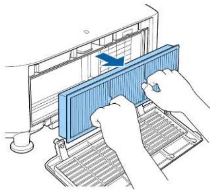
natural_image
Illustration of hands installing a blue filter component on a computer keyboard (no text or symbols visible)4 With the front (the side with tabs) of the air filter facing down, tap the air filter four or five times to shake off the dust. Turn it over and tap the other side in the same way.
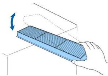
natural_image
Illustration of a hand holding a blue rectangular object with a rotating arrow, no text or symbols presentAttention
If the air filter is hit too hard, it may become unusable due to deformities and cracks.
5 Remove any dust remaining on the air filter by using a vacuum cleaner from the front side.

natural_image
Line drawing of a pipette dispensing liquid into a grid-lined rectangular container (no text or symbols)6 Replace the air filter.

natural_image
Diagram of a computer monitor with a blue rack and ventilation panel, showing airflow direction (no text or symbols)7 Close the air filter cover and tighten the fixing screws.

text_image
Diagram showing airflow or ventilation process on a device with numbered annotations indicating steps ① and ②.
- If a message is frequently displayed, even after cleaning, it is time to replace the air filter. Replace it with a new air filter.
"Replacing the Air Filter" p.208 - It is recommended that you clean the air filter every 20,000 hours. Clean it more often than this if using the projector in a particularly dusty environment.
- The indicators or messages regarding Air Filter Notice are displayed only when Air Filter Notice is set to On from the Configuration menu.
Extended - Display - Air Filter Notice p.146
Cleaning the air intake vent
1 After you turn off the projector's power and the confirmation buzzer beeps, disconnect the power cord.
2 Use a vacuum cleaner or a soft brush to carefully remove the dust.

natural_image
Line drawing of a projector with a magnified inset showing a screen (no text or symbols)Replacing Consumables

208
This section explains how to replace the air filter.
Replacing the Air Filter
Air filter replacement period
If the message is displayed frequently even though the air filter has been cleaned, replace the air filter.
Replacing the air filter
The air filter can be replaced even when the projector is suspended from a ceiling.
1 After you turn off the projector's power and the confirmation buzzer beeps, disconnect the power cord.
2 Loosen the fixing screws and open the air filter cover.
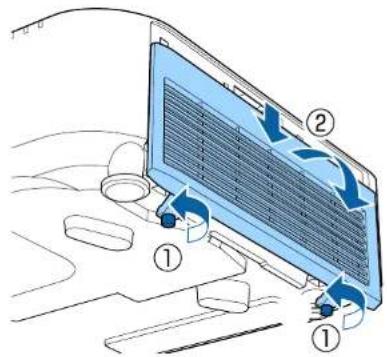
text_image
Diagram showing airflow or ventilation process on a computer monitor with labeled components ① and ②3 Remove the air filter.
Grip the tab of the air filter, and pull it straight out.

natural_image
Illustration of hands installing a blue filter component on a computer monitor (no text or symbols visible)4 Install the new air filter.

natural_image
Diagram of a blue heat exchanger mounted on a metal rack, with no visible text or symbols5 Close the air filter cover and tighten the fixing screws.

text_image
Diagram showing airflow or ventilation process on a device with numbered annotations indicating steps ① and ②.
Dispose of used air filters properly in accordance with your local regulations.
Material of the frame part: Polypropylene
Material of the filter part: Polypropylene
Panel Alignment
Adjusts the pixel color shift for the LCD panel. You can adjust the pixels horizontally and vertically by 0.125 pixels within a range of ±3 pixels.

- Image quality may decline after performing LCD alignment.
- Images for pixels that extend beyond the edge of the projected screen are not displayed.
1 Press the Menu button while projecting.
2 Select Display from Extended.
3 Select Panel Alignment, and then press the [←] button.

text_image
[Display] Return Menu Position Message Position Top Messages Off Display Background Off Startup Screen Off Standby Confirmation Off Air Filter Notice Off Screen Panel Alignment Color Uniformity OSD Rotation Off [Esc] :Return [◆]:Select [●]:Enter [Menu]:Exit4 Enable Panel Alignment.
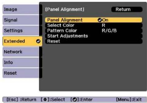
text_image
[Panel Alignment] Return Signal Settings Extended Select Color R Pattern Color R/G/B Start Adjustments Reset Network Info Reset [Esc] :Return [◆]:Select [●]:Enter [Menu]:Exit(1) Select Panel Alignment, and then press the [←] button.
(2) Select On, and then press the [←] button.
(3) Press the Esc button to return to the previous screen.
5 Select the color you want to adjust.
(1) Select Select Color, and then press the [←] button.
(2) Select R (red) or B (blue), and then press the [←] button.
(3) Press the Esc button to return to the previous screen.
6 Select the grid color displayed when making adjustments from Pattern Color.
(1) Select Pattern Color, and then press the [←] button.
Image Maintenance

(2) Select a combination of R (red), G (green), and B (blue) for the grid color.
R/G/B: Displays a combination all three colors; red, green and blue. The actual color of the grid is white.
R/G: This is available when R is selected from Select Color. Displays a combination of two colors; red and green. The actual color of the grid is yellow.
G/B: This is available when B is selected from Select Color. Displays a combination of two colors; green and blue. The actual color of the grid is cyan.
(3) Press the Esc button to return to the previous screen.
7 Select Start Adjustments, and then press the [◀] button. First, select Shift the whole panel to adjust the entire LCD panel. When the start confirmation message is displayed, press the◀] button to start adjustment.

The image may become distorted while adjusting. The image is restored once adjustments are complete.
8 Use the [▲][▼][◀][▶] buttons to make adjustments, and then press the ⏻ button.
9 To perform more detailed adjustments, select Adjust the four corners, and then press the button to confirm.
10 Use the [▲], [▼], [◀], and [▶] buttons to make adjustments, and then press the [◀] button to move to the next adjustment point.
11 When you have adjusted all four corners, select Exit, and then press the 📁 button.
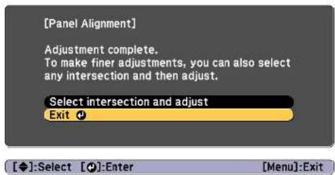
text_image
[Panel Alignment] Adjustment complete. To make finer adjustments, you can also select any intersection and then adjust. Select intersection and adjust Exit ⚙ [◆]:Select [●]:Enter [Menu]:ExitIf you feel you still need to make adjustments after correcting all four points, select Select intersection and adjust and then continue making adjustments.
Color Uniformity
Adjusts the color tone for the whole screen.

The color tone may not be uniform even after performing color uniformity.
1 Press the Menu button while projecting.
2 Select Display from Extended.
3 Select Color Uniformity, and then press the [←] button. The following screen is displayed.
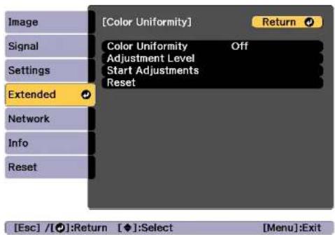
text_image
[Color Uniformity] Return Color Uniformity Off Adjustment Level Start Adjustments Reset Extended Network Info Reset [Esc] /[●]:Return [◆]:Select [Menu]:ExitColor Uniformity: Turns color uniformity on or off.
Adjustment Level: There are eight levels from white, through gray, and up to black. You can adjust each level individually.
Start Adjustments: Starts adjusting color uniformity.
Reset: Resets all adjustments and settings for Color Uniformity to their default values.

The image may become distorted while adjusting Color Uniformity. The image is restored once adjustments are complete.
4 Select Color Uniformity, and then press the [←] button.
5 Set to On, and then press the Esc button.
6 Select Adjustment Level, and then press the [←] button.
7 Use the [ ][ ] buttons to set the adjustment level.
8 Press the Esc button to return to the previous screen.
9 Select Start Adjustments, and then press the [←] button.
10 Select the area you want to adjust, and then press the [] button.
Adjust the outer areas first, and then adjust the whole screen.
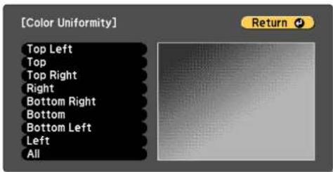
text_image
[Color Uniformity] Top Left Top Top Right Right Bottom Right Bottom Bottom Left Left All Return11 Use the [▲][▼] buttons to select the color you want to adjust, and then use the ⬆[▶]buttons to adjust.
Press the [◀] button to weaken the color tone. Press the [ ] button to strengthen the color tone.

text_image
[Color Uniformity] All Adjustment Level Red 0 Green 0 Blue 0[Default] :Reset [○]:Switch Background
12 Return to step 6 and adjust each level.
13 To complete the adjustment, press the Menu button.

Appendix
Epson Projector Management
Epson Projector Management lets you carry out operations such as checking the status of multiple Epson projectors that are connected to a network at a computer monitor, and controlling the projectors from the computer.
Download the Epson Projector Management software from the following website.
http://www.epson.com
Changing Settings Using a Web Browser (Epson Web Control)
By using a Web browser of a computer or mobile device connected to the projector on a network, you can set functions and control the projector. This function allows you to perform setup and control operations remotely.
You can use the following Web browsers.
- Internet Explorer 11.0 or later (except for Metro) (Windows)
- Microsoft Edge (Windows)
•Safari (Mac) - Chrome (Android)

If you set Standby Mode to Communication On, you can use the Web browser to make settings and perform control even if the projector is in standby mode (when the power is off).
Extended - Standby Mode p.146
Displaying the Epson Web Control Screen
Use the following procedure to display the Epson Web Control screer. Make sure your device and projector are ready for the network connection.

If your Web browser is set up to connect via a proxy server, the Epson Web Control screen cannot be displayed. To display Web Control, you need to make settings so that a proxy server is not used for a connection.
1 Connect your device to the same network as the connected projector.
The connection method varies depending on the device. See the manual supplied with your device for details. When using a mobile device, check the Wi-Fi settings.
2 Start the Web browser on your device.
3 Connect by entering the address of the connected projector in the URL field of the Web browser.
The Home screen is displayed.
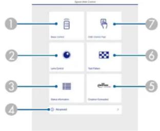
text_image
1 2 3 4 5 6 7 Read Control Data Source Path Lyme Control Text Patterns Text Information Designer Connected Arrayset1 Basic Control
"Basic Control Screen" p.216
② Lens Control
"Lens Control Screen" p.218
③ Status Information
"Status Information Screen" p.220
4 Advanced
You are moved to the Advanced screen.
⑤ Crestron Connected
"About Crestron Connected®" p.228
6 Test Pattern
"Test Pattern Operation Screen" p.219
7 OSD Control Pad
"OSD Control Pad Screen" p.217

- When performing the functions from the Home screen, you may be prompted to enter the user name and password. When the login screen is displayed, enter your user name and password. (The user name is EPSONWEB; the default password is admin.)
- You cannot change the user name. You can change the password in the Network menu from the Configuration menu.
Network - Basic - Web Control Password p.153
- You must enter the user name for Web Control Password even when the password is disabled.
- You can only set the following items from the Advanced screen.
Monitor Password (up to 16 single-byte alphanumeric characters)
Network - Basic - Monitor Password p.153
IPv6 Settings (Manual)
Network - IPv6 Settings p.154, p.157
Add HTTP port (for the port number used for Web control, use anything except for 80 (default), 843, 3620, 3621, 3625, 3629, 4352, 4649, 5357, 10000, 10001, 41794)
Network - Others p.159
Basic Control Screen
You can perform basic projector operations.
When the login screen is displayed, enter your user name and password.
(The user name is EPSONREMOTE; the default password is guest.)
Monitoring and Controlling


text_image
① ② ③ ④ HDMI HDMI HDBT DVI-D BNC① Moves to the Home screen.
② Turns the projector on.
③ Switches to the target image.
4 Turns the video and audio on or off.
⑤ Automatically detects the input signal.
6 Turns the projector off.
OSD Control Pad Screen
You can operate the Configuration menu of the projector.

text_image
1 2 3 4 5 6 QSO Control Panel 7 8 9 10 11 12 13 14 15 16 17 18 19 20 21 22 23 24 25 26 27 28 29 30 31 32 33 34 35 36 37 38 39 40① Moves to the Home screen.
② Displays and closes the Configuration menu.
③ You can operate the Configuration menu using your finger or mouse. Flick to select an item, and tap to confirm the selection.
4 Enabled when Default: Reset is displayed on the Configuration menu guide. The settings being adjusted are returned to their default values.
⑤ Returns to the previous menu level in the Configuration menu.
6 Displays information on using the OSD Control Pad.

Items in the Configuration menu that cannot be set in Epson Control are listed below.
- Image menu - Advanced - Gamma - Custom
- Signal menu - Advanced - BNC Sync Termination, EDID, DDC Buffer
- Settings menu - HDMI Link, User Button, Content Playback
•Extended menu - Display - Message Position
•Extended menu - User's Logo - Extended menu - Operation - Advanced - Lens Type
- Extended menu - Operation - Lens Calibration
•Extended menu - Language
•Network menu - Search Access Point, Crestron Connected
The settings for items on each menu are the same as the projector's Configuration menu.
"Configuration Menu" p.135
Lens Control Screen
You can operate the lens of the projector.
Focus/Distortion Operation Screen

text_image
1 2 3 4 5 Laser Sensitive - + - + - Project Function Screw Lens Shell Tool Trigger Memory 6 7 8 9 10① Moves to the Home screen.
② Move the slider to adjust the focus.
③ Press the buttons to adjust the focus.
4 Move the slider to adjust image warping.
⑤ Press the buttons to adjust image warping.
6 Displays the Focus / Distortion operation screen.
⑦ Displays the Zoom operation screen.
⑧ Displays the Lens Shift operation screen.
9 Displays the Test Pattern operation screen.
⑩ Displays the Memory operation screen.
* This is not available for ELPLU02.
Zoom Operation Screen
This is not available for ELPLX01, ELPLX01W, and ELPLR04.
Monitoring and Controlling


text_image
① ② T W Focal Diameter Size Left Shift Top Shift None① Move the slider to adjust the zoom.
② Press the buttons to adjust the zoom.
Lens Shift Operation Screen

text_image
C Hense Laser Shift ① ② V-Shift D H-Shift D ③ < 3 4 Penset / Subset Zoom Lock Shift Text Pattern Sensor① Displays the position of the image as a blue square. When you move the image position, a red square is displayed at the destination.
② Displays the vertical image position. You can directly specify the position by tapping it and entering a number.
③ Moves the image position up, down, left, or right.
4 Moves the lens position to the home position if you press the OK button in the confirmation screen.
⑤ Displays the horizontal image position. You can directly specify the position by tapping it and entering a number.
Test Pattern Operation Screen

text_image
C Name Test Pattern Check ① ② 1 2 3 4 5 6 7 8 9 10 11 12 13 14 15 16 17 18 19 20 21 22 23 24 25 26 27 28 29 30 31 32 33 34 35 36 37 38 39 40 41 42 43 44 45 46 47 48 49 50 51 52 53 54 55 56 57 58 59 60 61 62 63 64 65 66 67 68 69 70 71 72 73 74 75 76 77 78 79 80 81 82 83 84 85 86 87 88 89 90 91 92 93 94 95 96 97 98 99 100① Displays a test pattern.
② Closes the test pattern.
Memory Operation Screen
See the following for memory function details.
"Memory Function" p.110
Monitoring and Controlling

220

text_image
1 2 3 4 5 6 7 8 9 10 11 12 13 14 15 16 17 18 19 20 21 22 23 24 25 26 27 28 29 30 31 32 33 34 35 36 37 38 39 40 41 42 43 44 45 46 47 48 49 50 51 52 53 54 55 56 57 58 59 60 61 62 63 64 65 66 67 68 69 70 71 72 73 74 75 76 77 78 79 80 81 82 83 84 85 86 87 88 89 90 91 92 93 94 95 96 97 98 99 100① Loads a memory.
② Saves a memory.
③ Displays a list of memories.
4 Erases a memory.
⑤ Changes a memory name.
Status Information Screen
You can check the projector's status. See the following for display details.
"Reading the Status Display" p.182

text_image
① ② ③ ④ Data Information Data To Print/Export Auto Tools Auto Tools Auto Tools Auto Tools1 Moves to the Home screen.
② Displays the item name.
③ Displays the status of each item.
4 Selects a category from the following.
Status Information, Source, Signal Information, Network Wired, Network Wireless, Maintenance, Version, Air Temp Info
Changing Settings Using a Web Browser (Content Playback Mode)
In Content Playback mode, you can use a Web browser to set and control network projectors, and edit playlists.

You can also control projectors using a Web browser from Epson iProjection (iOS/Android).
Attention
Do not remove the USB flash drive from the projector or unplug the power cord in the following situations. Otherwise, data on the USB flash drive may be corrupted.
●While viewing the Playlist screen
●While viewing the USB flash drive screen
1 Make sure that the projector is in Content Playback mode.
2 Connect your device to the same network as the connected projector.
3 Start the Web browser on your device. Enter the IP address of the projector in the address input box of the browser to connect to the Epson Web Control screen. When entering an IPv6 address, enclose the address in square brackets [].
The Epson Web Control screen is displayed.

flowchart
graph TD
    A["1"] --> B["Remote"]
    B --> C["Playlists"]
    C --> D["USB Memory Device"]
    E["2"] --> F["Time Table"]
    F --> G["OSD Control Pad"]
    G --> H["Lens Control"]
    I["3"] --> J["Test Patterns"]
    J --> K["Status Information"]
    K --> L["Creation Connected"]
    M["4"] --> N["Advanced"]
    O["5"] --> P["Developer's Menu"]
    Q["6"] --> R["Developer's Menu"]
    S["7"] --> T["Developer's Menu"]
    U["8"] --> V["Developer's Menu"]
    W["9"] --> X["Developer's Menu"]
    Y["10"] --> Z["Developer's Menu"]
① You can use this to operate the projector remotely.
② Edit the playlist you want to play in Content Playback mode.
③ Displays the Timetable screen.
4 Operate the Configuration menus using your finger or mouse.
⑤ Displays a test pattern.
6 Displays the projector's status.
⑦ Make advanced settings for the projector.
⑧ Displays the Crestron Connected operation screen. This is only enabled when using Crestron Connected.
9 Operate the lens of the projector.
⑩ Save the data for your playlists to a USB flash drive.
4 Select the item you want to use.

You may need to login to set options on the Epson Web Control screen. When the login screen is displayed, enter your user name and password.
(The user name is EPSONWEB; the default password is admin.)
- You can change the password in Web Control Password from the Network.
Network - Network Configuration - Basic - Web Control Password p.153
- You can only set the following items from Advanced. - Monitor Password (up to 16 single-byte alphanumeric characters)
- IPv6 Settings (Manual)
- Add HTTP port (for the port number used for Web control, use anything except for 0 (default), 843, 3620, 3621, 3625, 3629, 4352, 4649, 5357, 10000, 10001, 41794)
Remote

text_image
Home Remote Source Select HDMI HDBaseT DVI-D Computer BNC USB LAN A/V Note Volume - + Overlay Effect Favorite Playlists① Moves to the Epson Web Control home screen.
② Turns the projector on or off.
③ Selects the input source.
Turns the video and audio on or off temporarily.
⑤ Selects your favorite playlist.
6 Turns Overlay Effect on or off.
⑦ Adjusts the volume for the speakers.
Monitoring and Controlling

Playlists

text_image
Home Playlists Add New 1 2 3 4 playlist A 1 ... playlist B 2 ... playlist C 3 ... playlist D 4 ...① Moves to the Epson Web Control home screen.
② Controls playback of the playlist.
③ Edits the playlist.
4 Creates a new playlist.
USB Memory Device

text_image
Home USB Memory Device Free Space on USB Memory Device Upload Data Delete Data Uploaded Data① Moves to the Epson Web Control home screen.
② Saves photos and videos you want to add to your playlists to the USB flash drive.
③ Deletes photos and videos from the USB flash drive.
Time Table

text_image
Home Time Table Time Table Time Table (20:18:00:19) 07:00-12:00 1 playtot A 12:00-18:00 2 playtot B 18:00-21:30 3 playtot C playtot B1 Moves to the Epson Web Control home screen.
② Turns the timetable on or off.

The timetable feature in Epson Projector Content Manager to specify when the playlist will be played.
See the "Epson Projector Content Manager Operation Guide" for details.
OSD Control Pad
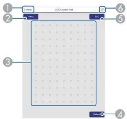
text_image
1 2 Name GSD Control Pad 3 BSS 6 5 4 Default① Moves to the Epson Web Control home screen.
② Displays the Configuration menu.
③ Operate the menus using your finger or mouse.
4 Enabled when Default: Reset is displayed on the menu guide. The settings being adjusted are returned to their default values.
⑤ Returns to the previous menu.
Displays the help topics.

See the following for items in the Configuration menu that cannot be set in Epson Web Control.
"OSD Control Pad Screen" p.217
Using the Mail Notification Function to Report Problems
When you set Mail Notification, notification messages are sent to the preset email addresses when a problem or warning occurs with a projector. This will enable the operator to be notified of problems with projectors even at locations away from the projectors.
Network - Notifications - Mail Notification p.158

- Up to a maximum of three notification destinations (addresses) can be registered, and notification messages can be sent to all three destinations at once.
- If a projector develops a critical problem and suddenly stops working, it may not be able to send a message notifying an operator of the problem.
- If you set Standby Mode to Communication On, you can control the projector even if it is in standby mode (when the power is off).
Extended - Standby Mode p.146
Reading error notification mail
When the Mail Notification function is set to On and a problem or warning occurs in the projector, the following email will be sent.
Sender: The email address set in From
Subject: EPSON Projector
Line 1: The projector name where the problem has occurred
Line 2: The IP address set for the projector where the problem has occurred.
Line 3 and on: Details of the problem
The details of the problem are listed line by line. The main message contents are listed below.
- Clean Air Filter
- Constant brightness expired (Constant Bright. End)
- Internal error
- Fan related error
- Sensor error
- Laser error (Laser Error/Laser Does Not Turn On)
- Laser warning
•Retardation Plate Error - Internal temperature error
•High-speed cooling in progress - Low Air Flow
- Low Air Flow Error
- No-signal
No Signal is input to the projector. Check the connection status or check that the power for the signal source is turned on.
- Lens shift error
- No lens
See the following to deal with problems or warnings.
"Reading the Indicators" p.175
Management Using SNMP
By setting SNMP to On in the Configuration menu, notification messages are sent to the specified computer when a problem or warning occurs. This allows you to check for problems with projectors even at locations away from the projectors.
Network Notifications SNMP p.158

•SNMP should be managed by a network administrator or someone who is familiar with the network.
•To use the SNMP function to monitor the projector, you need to install the SNMP manager program on your computer.
•The SNMP Agent for this projector complies with version 1 (SNMPv1).
•The managing function using SNMP cannot be used over wireless LAN in Quick connection mode.
•Up to two destination IP addresses can be saved.
ESC/VP21 Commands
You can control the projector from an external device using ESC/VP21.
Command list
When the power ON command is transmitted to the projector, the power turns on and it enters warm-up mode. When the projector's power has turned on, a colon ":" (3Ah) is returned.
When a command is input, the projector executes the command and returns a ":", and then accepts the next command.
If the command being processed terminates abnormally, an error message is output and a ":" is returned.
The main contents are listed below.
| Item Command | |||
| Power ON/OFF | On PWR ON | ||
| Off PWR OFF | |||
| Signal selection | Computer Auto SOURCE | RCE 1F | |
| RGB SOURCE 11 | |||
| Component SOURCE 14 | |||
| BNC Auto SOURCE | BF | ||
| RGB SOURCE B1 | |||
| Component SOURCE B4 | |||
| HDMI SOURCE 30 | |||
| USB | SOURCE 52 | ||
| LAN | SOURCE 53 | ||
| DVI-D | SOURCE A0 | ||
| IIDBaseT | SOURCE 80 | ||
| A/V Mute On/Off | On MUTE ON | ||
| Off MUTE OFF | |||
Add a Carriage Return (CR) code (0Dh) to the end of each command and transmit.
For more details, contact your local dealer or the nearest address provided in the Epson Projector Contact List.
Epson Projector Contact List
Cable layouts
Serial connection
- Connector shape: D-Sub 9-pin (male)
-Projector input port name: RS-232C
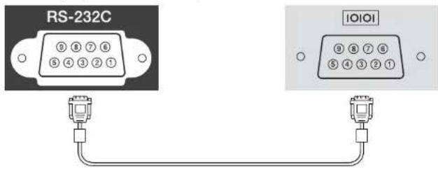
text_image
RS-232C IOIOI| GND | 5 | 5 | GND | |
| TD | 3 | 3 | TD | |
| RD | 2 | 2 | RD |
| Signal Name Function | |
| GND | Signal wire ground |
| TD | Transmit data |
| RD | Receive data |
Communications protocol
- Default baud rate setting: 9600 bps
•Data length: 8 bit - Parity: None
-Stop-bit: 1 bit - Flow control: None
About PJLink
PJLink was established by the JBMIA (Japan Business Machine and Information System Industries Association) as a standard protocol for controlling network-compatible projector's as part of their efforts to standardize projector control protocols.
The projector complies with the PJLink Class2 standard established by the JBMLA.
The port number used by the PJLink search function is 4352 (UDP).
You need to make network settings before you can use PJLink. See the following for more information on network settings.
"Network Menu" p.151
It complies with all commands except for the following commands defined by PJLink Class2, and agreement was confirmed by the PJLink standard adaptability verification.
URL: http://pjlink.jbmia.or.jp/english/
•Non-compatible commands
| Function PJLink Command | ||
| Mute settings Image | muting set AVMT 11 | |
| Audio muting set AVMT 21 | ||
- Input ports and corresponding input source number
| Input Port Name Input Source Number | |
| Computer 11 | |
| BNC 13 | |
| DVI-D | 31 |
| HDMI | 32 |
| USB 41 | |
| LAN 52 | |
| HDBaseT 56 | |
- Manufacturer name displayed for "Manufacture name information query" EPSON
- Model name displayed for "Product name information query" EPSON L1075U/L1070U
EPSON L1065U/L1060U
EPSON L1050U
EPSON L1070W
EPSON L1060W
EPSON L1070
About Crestron Connected®
Crestron Connected ^® is an integrated control system provided by Crestron ^® . It can be used to monitor and control multiple devices connected on a network.
The projector supports the control protocol, and can therefore be used in a system built with Crestron Connected
Visit the Crestron® Web site for details on Crestron Connected. (Only English-language displays are supported.)
https://www.crestron.com/products/line/crestron-connected
The following provides an overview of Crestron Connected
- Remote operation using a Web browser
You can operate a projector from your computer just like using a remote control.
•Monitoring and control with application software
You can use Crestron RoomView® Express/Crestron Fusion® provided by Crestron® to monitor devices in the system, to communicate with the help desk, and to send emergency messages.
This manual describes how to perform operations on your computer using a Web browser.

- You can only enter single-byte alphanumeric characters and symbols.
- The Message Broadcasting feature for Epson Projector Management is unavailable while using Crestron Connected
- If you set Standby Mode to Communication On, you can control the projector even if it is in standby mode (when the power is off).
Extended - Standby Mode p.146
Operating a projector from your computer
Displaying the operation window
Check the following before carrying out any operations.
- Make sure the computer and projector are connected to the network.
- Set Crestron Connected to On from the Network menu.
Network - Others - Crestron Connected p.159
1 Start the Web browser on the computer.
Monitoring and Controlling

229
2 Enter the IP address of the projector in the address field of the Web browser, and press the Enter key on the keyboard.
The Epson Web Control home screen is displayed.
3 Press Crestron Connected.
The operation window is displayed.
Using the operation window
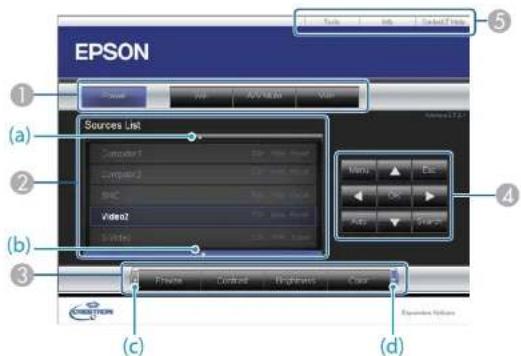
text_image
EPSON (a) (b) (c) (d) Sources List Computer1 Computer2 SBC Video2 SMTM Menu Esc Go Add Delete Expenses Options① You can perform the following operations when you click the buttons.
| Button Function | |
| Power Turns the projector | power on or off. |
| Vol-/Vol+ Adjusts the volume. | |
| Button Function | |
| A/V Mute Turns the video | and audio on or off. "Hiding the Image and Sound Temporarily (A/V Mute)" p.102 |
② Switch to the image from the selected input source. To display input sources that are not shown in Source List, click (a) or (b) to scroll up or down. The current video signal input source is displayed in blue.
You can change the source name if necessary.
3 You can perform the following operations when you click the buttons. To display buttons that are not shown in Source List, click (c) or (d) to scroll left or right.
| Button Function | |
| Freeze Images are paused or unpaused. | "Freezing the Image (Freeze)" p.103 |
| Contrast Adjusts the difference between light and shade in the images. | |
| Brightness Adjusts the image brightness. | |
| Color Adjusts the color saturation for the images. | |
| Sharpness Adjusts the image sharpness. | |
| Zoom | Click the [∅] button to enlarge the image without changing the projection size. Click the [∅] button to reduce the image that was enlarged with the [∅] button. Click the [▲] [▼] [▼buttons to change the position of an enlarged image. "Enlarging Part of the Image (E-Zoom)" p.104 |
④ The [▲] [▼] [◀] [▶] buttons perform the same operations as the [▲] [▼] [◀] [▶] buttons on the remote control. You can perform the following operations when you click the other buttons.
Monitoring and Controlling

| Button Function | |
| OK | Performs the same operation as the [ ↙] button on the remote control.⇨ "Remote Control" p.20 |
| Menu Displays and closes the Configuration menu. | |
| Auto | If clicked while projecting analog RGB signals from the Computer port, you can automatically optimize Tracking, Sync., and Position. |
| Search Changes to the next input source that is sending an image.⇨ "Automatically Detecting Input Signals and Changing the Projected Image (Source Search)" p.61 | |
| Esc Performs the same operation as the [Esc] button on the remote control.⇨ "Remote Control" p.20 | |
5 You can perform the following operations when you click the tabs.
| Tab Function | |
| Help Displays the Help Desk | window. Used to send messages to, and receive messages from, the administrator using Crestron Connected®. |
| Info Displays information | on the projector that is currently connected. |
| Tools Changes settings in | the projector that is currently connected. See the next section. |
Using the tools window
The following window is displayed when you click the Tools tab on the operation window. You can use this window to change settings in the projector that is currently connected.

text_image
EPSON Creation Control Projector User Password P Address: 182.1664.0 Projector Name: E80001.54 Location: EPSON Added To: 2008 Add To: New Password C:\Users\Password C:\Users\Password C:\Users\Password C:\Users\Password C:\Users\Password C:\Users\Password C:\Users\Password C:\Users\Password C:\Users\Password C:\Users\Password C:\Users\Password C:\Users\Password C:\Users\Password C:\Users\Password C:\Users\Password C:\Users\Password C:\Users\Password C:\Items\Password C:\Items\Password C:\Items\Password C:\Items\Password C:\Items\Password C:\Items\Password C:\Items\Password C:\Items\Password C:\Items\Password C:\Items\Password C:\Items\Password C:\Items\Password C:\Items\Password C:\Items\Password C:\Items\Password C:\Items\Password C:\Items\Password D:\Users\Password D:\Items\Password D:\Items\Password D:\Items\Password D:\Items\Password D:\Items\Password D:\Items\Password D:\Items\Password D:\Items\Password D:\Items\Password D:\Items\Password D:\Items\Password D:\Items\Password D:\Items\Password D:\Items\Password D:\Items\Password D:\Items\Password D:\Items\Password E361 Crestron Control
Make settings for Crestron ^® central controllers.
② Projector
The following items can be set.
| Item Function | |
| Projector Name | Enter a name to differentiate the projector that is currently connected from other projectors on the network. (The name can contain up to 15 single-byte alphanumeric characters.) |
| Location Enter an installation location name for the projector that is currently connected on the network. (The name can contain up to 32 single-byte alphanumeric characters and symbols.) | |
| Assigned To | Enter a user name for the projector. (The name can contain up to 32 single-byte alphanumeric characters and symbols.) |
Monitoring and Controlling

231
| Item Function | |
| DHCP Select the Enabled | check box to use DHCP. You cannot enter an IP address if DHCP is enabled. |
| IP Address | Enter the IP address to assign to the currently connected projector. |
| Subnet Mask Enter a subnet | mask for the currently connected projector. |
| Default Gateway Enter the gateway address for the currently connected projector. | |
| Scnd Click this button to confirm the changes made to the Projector. | |
3 Admin Password
Select the Enabled check box to require a password to open the Tools window. The following items can be set.
| Item Function | |
| New Password Enter the new password when changing the password to open the Tools window. (The name can contain up to 26 single-byte alphanumeric characters.) | |
| Confirm | Enter the same password as you entered in New Password. If the passwords are not the same, an error is displayed. |
| Scnd Click this button to confirm the changes made to the Admin Password. | |
4 User Password
Select the Enabled check box to require a password to open the operation window on the computer. The following items can be set.
| Item Function | |
| New Password Enter the new password when changing the password to open the operation window. (The name can contain up to 26 single-byte alphanumeric characters.) | |
| Confirm Enter the same password as you entered in New Password. If the passwords are not the same, an error is displayed. | |
| Send Click this button to confirm the changes made to the User Password. | |
About Web API
You can use Web API to operate the projector when Content Playback mode is enabled.
You can enable Web API from a Web browser.

You can apply API authentication (Digest authentication) to Web API communications.
The user name for API authentication is EPSONWEB; the password is the Web Control Password.
1 Open the Epson Web Control home screen in your Web browser.
2 Press Developer's Menu.
3 Set Enable API to On.
"Changing Settings Using a Web Browser (Epson Web Control)" p.215
The following Web API commands are supported by the projector.
| URL Supported methods Explanation | ||
| http://api/v01/contentmgr/remote/power/on | GET/POST/PUT | Turns on the projector.It takes a while for the Web API to respond. |
| http://api/v01/contentmgr/remote/power/off | GET/POST/PUT | Turns off the projector. |
| http://api/v01/contentmgr/playlist/play/:id | GET/POST/PUT | Plays the playlist with the specified ID.Enter the playlist ID in :id. You can check the playlist ID from the Developer's Menu on the home screen. |
| http://api/v01/contentmgr/playlist/stop | GET/POST/PUT | Stops the playlist. |
Enter the projector's IP address in
For example, the following URL commands the projector with the IP address 192.168.0.2 to play the playlist with the ID 3.
http://192.168.0.2/api/v01/contentmgr/playlist/play/3
If secure HTTP is enabled, change the http in the URL to https.
Optional Accessories and Consumables

The following optional accessories and consumables are available. Please purchase these products as and when needed. The following list of optional accessories and consumables is current as of: June 2019. Details of accessories are subject to change without notice and availability may vary depending on the country of purchase.
Optional Accessories
| Lens unitELPLX01, ELPLX01W, ELPLU03, ELPLU04, ELPLW05, ELPLW06, ELPLW08, ELPLM08, ELPLM10, ELPLM11, ELPLM15, ELPLL08See the following for more information on the projection distance lens."Screen Size and Projection Distance" p.234 |
| Computer cable ELPKC02(1.8 m - for mini D-Sub15-pin/mini D-Sub 15pin) |
| Computer cable ELPKC09(3 m - for mini D-Sub15-pin/mini D-Sub 15pin)Computer cable ELPKC10(20 m - for mini D-Sub15-pin/mini D-Sub 15pin) |
| Remote control cable set ELPKC28(10 m 2 piece set)Use this to guarantee operation from the remote control from a distance. |
| HDBaseT Transmitter ELPHD01This transmitter performs long distance transmissions for HDMI signals an control signals for one LAN cable. Based on the HDBaseT standard. (HDCP 2.2 is not supported.) |
| Wireless LAN unit ELPAP10Use when connecting the projector to a computer wirelessly and projecting (Frequency band: 2.4 GHz) |
Polarizer ELPPL01
Use this when stacking two projectors and projecting 3D images.
Passive 3D Glasses (standard five piece set) ELPGS02A
Passive 3D Glasses (five piece set for children) ELPGS02B
Passive polarized 3D glasses. Use these when viewing 3D images with two projectors.
Document Camera ELPDC13, ELPDC21
Use when projecting images such as books, OHP documents, or slides.
Pipe 450 (450 mm) ^* ELPFP13
Pipe 700 (700 mm) ^* ELPFP14
Use when installing the projector on a high ceiling.
Ceiling mount\* ELPMB22
Low ceiling mount* ELPMB47
High ceiling mount* ELPMB48
Use when installing the projector on a ceiling. Do not use for any other purpose.
* Special techniques are required to suspend the projector from a ceiling. Contact your local dealer or the nearest address provided in the Epson Projector Contact List.
Epson Projector Contact List
Consumables
Air filters ELPAF46
Use as a replacement for used air filters.
Projection Distances for EB-L1075U/EB-L1070U/EB-L1065U/EB-L1060U/EB-L1050U/EB-L1070W/EB-L1060W

text_image
Diagram illustrating a geometric or optical setup with labeled components and measurement lines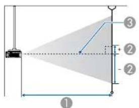
text_image
Diagram showing a geometric setup with labeled components and shaded triangular region, likely illustrating a perspective or projection system.① Projection distance
② is the distance from the center of the lens to the base of the screen. This changes depending on the setting for vertical lens shift.
③ Center of lens

If the screen is larger than 300 inches, fine text and images may not be displayed clearly.
ELPLM08
This section shows the projection distances for models equipped with standard lenses.
Unit: cm
| 4:3 Screen Size | 1 | 2 | |
| Minimum (Wide) to Maximum (Tele) | Vertical lens shift Bottom to Top | ||
| 45" 100x75 156 to 253 -81 to +12 | |||
| 50" 102x76 174 to 281 -90 to +13 | |||
| 60" 122x91 210 to 338 -108 to +16 | |||
| 80" 163x122 281 to 453 -143 to +22 | |||
| 100" 203x152 353 to 567 -179 to +27 | |||
| 120" 244x183 424 to 681 -215 to +32 | |||
| 150" 305x229 532 to 853 -269 to +40 | |||
| 200" 406x305 711 to 1139 -359 to +54 | |||
| 250" 508x381 890 to 1424 -448 to +67 | |||
| 300" 610x457 1069 to 1710 -538 to +81 | |||
| 500" 1016x762 | 1785 to 2853 | -896 to +134 | |
| 800" | 1626x1219 | 2858 to 4568 | -1434 to +215 |
| 1000" | 2032x1524 | 3574 to 5711 | -1793 to +269 |
Unit: cm
| 16:9 Screen Size | 1 | 2 | |
| Minimum (Wide) to Maximum (Tele) | Vertical lens shift Bottom to Top | ||
| 49" 108x61 | 154 to 250 -76 | to +15 | |
| 50" 111x62 | 157 to 255 -78 | to +16 | |
| 60" 133x75 | 190 to 307 -94 | to +19 | |
Screen Size and Projection Distance

235
| 16:9 Screen Size | 1 | 2 | |
| Minimum (Wide) to Maximum (Tele) | Vertical lens shift Bottom to Top | ||
| 80" 177x | 100 255 to 411 -125 to +25 | ||
| 100" 221x | 125 320 to 514 -156 to +31 | ||
| 120" 266x | 149 385 to 618 -187 to +38 | ||
| 150" 332x | 187 482 to 774 -234 to +47 | ||
| 200" 413x | 249 645 to 1033 -312 to +63 | ||
| 250" 553x | 311 807 to 1293 -390 to +78 | ||
| 300" 664x | 374 970 to 1552 -468 to +94 | ||
| 500" 1107x | 623 1620 to 2590 -779 to +157 | ||
| 800" 177x | 996 2595 to 4147 -1247 to +251 | ||
| 1000" 221x | 1245 3244 to 5185 -1559 to +313 | ||
Unit: cm
| 16:10 Screen Size | 1 | 2 | |
| Minimum (Wide) to Maximum (Tele) | Vertical lens shift Bottom to Top | ||
| 50" | 108x67 | 153 to 248 | -79 to +12 |
| 60" | 130x81 | 185 to 298 | -95 to +14 |
| 80" 172x | 108 248 to 399 -127 to +19 | ||
| 100" 215x | 135 311 to 500 -158 to +24 | ||
| 120" 258x | 162 374 to 601 -190 to +29 | ||
| 150" 323x | 202 469 to 753 -238 to +36 | ||
| 200" 431x | 269 627 to 1005 -317 to +48 | ||
| 250" 538x | 337 785 to 1258 -396 to +59 | ||
| 300" 646x | 404 943 to 1510 -475 to +71 | ||
| 500" 1077x | 673 1576 to 2520 -792 to +119 | ||
| 16:10 Screen Size | 1 | 2 | |
| Minimum (Wide) to Maximum (Tele) | Vertical lens shift Bottom to Top | ||
| 800" | 1723x1077 2524 to 4035 -1267 to +190 | ||
| 1000" 2154x1346 3157 to 5044 -1584 to +238 | |||
ELPLX01/ELPLX01W
Zoom is not supported.
Unit: cm
| 4:3 Screen Size | 1 | 2 | |
| Vertical lens shiftBottom to Top | |||
| 89" 181x | 136 | 74 | 0 to +24 |
| 100" 203x | 152 | 84 | 0 to +27 |
| 120" 244x | 183 102 | 0 to +32 | |
| 150" 305x | 229 129 | 0 to +40 | |
| 200" 406x | 305 173 | 0 to +54 | |
| 250" 508x | 381 218 | 0 to +67 | |
| 300" 610x | 457 262 | 0 to +81 | |
| 350" 711x | 533 307 | 0 to +94 | |
| 500" 1016x | 762 440 | 0 to +134 | |
| 800" | 1626x1219 | 708 | 0 to +205 |
Unit: cm
| 16:9 Screen Size | 1 | 2 |
| Vertical lens shiftBottom to Top | ||
| 98" 217x122 | 74 | +7 to +31 |
| 16:9 Screen Size | 1 | 2 | |
| Vertical lens shiftBottom to Top | |||
| 100" 221x | 125 76 +7 to +31 | ||
| 120" 266x | 149 92 +8 to +38 | ||
| 150" 332x | 187 116 +10 to +47 | ||
| 200" 443x | 249 157 +14 to +63 | ||
| 250" 553x | 311 197 +17 to +78 | ||
| 300" 664x | 374 238 +21 to +94 | ||
| 350" 775x | 436 278 +24 to +110 | ||
| 500" 1107x | 623 399 +35 to +157 | ||
| 800" 1771x | 996 642 +55 to +251 | ||
Unit: cm
| 16:10 Screen Size | 1 | 2 | |
| Vertical lens shiftBottom to Top | |||
| 100" 215x135 74 0 to +24 | |||
| 120" 258x162 89 0 to +29 | |||
| 150" 323x202 113 0 to +36 | |||
| 200" 431x269 152 0 to +48 | |||
| 250" 538x337 192 0 to +59 | |||
| 300" 646x404 231 0 to +71 | |||
| 350" 754x471 270 0 to +83 | |||
| 400" 862x538 310 0 to +95 | |||
| 500" 1077x673 388 0 to +119 | |||
| 800" 1723x1077 625 0 to +190 | |||
| 1000" | 2154x1346 782 0 to +238 | ||
ELPLU03
Unit: cm
| 4:3 Screen Size | 1 | 2 | |
| Minimum (Wide) to Maximum (Tele) | Vertical lens shift Bottom to Top | ||
| 71" | 144x108 | 112 to 135 -127 to +19 | |
| 80" | 163x122 | 126 to 152 -143 to +22 | |
| 100" 203x152 | 159 to 191 -179 to +27 | ||
| 120" 244x183 | 191 to 230 -215 to +32 | ||
| 150" 305x229 | 240 to 289 -269 to +40 | ||
| 200" 406x305 | 321 to 386 -359 to +54 | ||
| 250" 508x381 | 403 to 483 -448 to +67 | ||
| 300" 610x457 | 484 to 581 -538 to +81 | ||
| 500" 1016x762 | 809 to 971 -896 to +134 | ||
| 800" 1626x1219 | 1297 to 1555 | -1434 to +215 | |
Unit: cm
| 16:9 Screen Size | 1 | 2 | |
| Minimum (Wide) to Maximum (Tele) | Vertical lens shift Bottom to Top | ||
| 78" | 173x97 | 111 to 134 -122 to +24 | |
| 80" | 177x100 | 114 to 138 -125 to +25 | |
| 100" 221x125 | 144 to 173 -156 to +31 | ||
| 120" 266x149 | 173 to 209 -187 to +38 | ||
| 150" 332x187 | 218 to 262 -234 to +47 | ||
| 200" 443x249 | 291 to 350 -312 to +63 | ||
| 250" 553x311 | 365 to 439 -390 to +78 | ||
| 300" 664x374 | 439 to 527 -468 to +94 | ||
| 500" 1107 | x623 734 to 881 | -779 to +157 | |
| 800° 1771 | x996 1177 to 1412 | -1247 to +251 | |
Unit: cm
| 16:10 Screen Size | 1 | 2 | |
| Minimum (Wide) to Maximum (Tele) | Vertical lens shift Bottom to Top | ||
| 80" 172x | 108 111 to 134 -127 to +19 | ||
| 100" 215x | 135 140 to 168 -158 to +24 | ||
| 120" 258x | 162 169 to 203 -190 to +29 | ||
| 150" 323x | 202 212 to 255 -238 to +36 | ||
| 200" 431x | 269 283 to 341 -317 to +48 | ||
| 250" 538x | 337 355 to 427 -396 to +59 | ||
| 300" 646x | 404 427 to 513 -475 to +71 | ||
| 500" 1077 | x673 714 to 857 -792 to +119 | ||
| 800" 1723 | x1077 1145 to 1373 -1267 to +190 | ||
| 1000" 2154 | x1346 1432 to 1717 -1584 to +238 | ||
ELPLU04/ELPLU02
Unit: cm
| 4:3 Screen Size | 1 | 2 | |
| Minimum (Wide) to Maximum (Tele) | Vertical lens shift Bottom to Top | ||
| 45" | 100x75 | 93 to 113 | -81 to +12 |
| 50" | 102x76 | 104 to 126 | -90 to +13 |
| 4:3 Screen Size | 1 | 2 | |
| Minimum (Wide) to Maximum (Tele) | Vertical lens shift Bottom to Top | ||
| 60" | 122x91 | 126 to 153 -108 to +16 | |
| 80" 163x | 122 170 to 205 -143 to +22 | ||
| 100" 203x | 152 214 to 258 -179 to +27 | ||
| 120" 244x | 183 258 to 311 -215 to +32 | ||
| 150" 305x | 229 324 to 390 -269 to +40 | ||
| 200" 406x | 305 434 to 522 -359 to +54 | ||
| 250" 508x | 381 543 to 654 -448 to +67 | ||
| 300" 610x | 457 653 to 786 -538 to +81 | ||
| 500" 1016x | 762 1092 to 1313 | -896 to +134 | |
| 800" 1626x | 1219 1751 to 2105 -1434 to +215 | ||
Unit: cm
| 16:9 Screen Size | 1 | 2 | |
| Minimum (Wide) to Maximum (Tele) | Vertical lens shift Bottom to Top | ||
| 49" | 108x61 | 92 to 112 | -76 to +15 |
| 50" | 111x62 | 94 to 114 | -78 to +16 |
| 60" | 133x75 | 114 to 138 | -94 to +19 |
| 80" 177x | 100 154 to 186 -125 to +25 | ||
| 100" 221x | 125 194 to 234 -156 to +31 | ||
| 120" 266x | 149 234 to 282 -187 to +38 | ||
| 150" 332x | 187 293 to 354 -234 to +47 | ||
| 200" 443x | 249 393 to 473 -312 to +63 | ||
| 250" 553x | 311 493 to 593 -390 to +78 | ||
| 300" 664x | 374 592 to 713 -468 to +94 | ||
| 500" 1107 | x623 991 to 1192 | -779 to +157 | |
| 800" 1771 | x996 1589 to 1910 | -1247 to +251 | |
Unit: cm
| 16:10 Screen Size | 1 | 2 | |
| Minimum (Wide) to Maximum (Tele) | Vertical lens shift Bottom to Top | ||
| 50" 108x | 57 91 to 111 -79 to +12 | ||
| 60" 130x | 81 111 to 134 -95 to +14 | ||
| 80" 172x | 108 149 to 181 | -127 to +19 | |
| 100" | 215x135 188 to 227 | -158 | to +24 |
| 120" | 258x162 227 to 274 | -190 | to +29 |
| 150" | 323x202 285 to 344 | -238 | to +36 |
| 200" | 431x269 382 to 460 | -317 | to +48 |
| 250" | 538x337 479 to 577 | -396 | to +59 |
| 300" | 646x404 576 to 693 | -475 | to +71 |
| 500" 1077 | x673 964 to 1159 | -792 to +119 | |
| 800" | 1723x1077 | 1546 to 1858 | -1267 to +190 |
| 1000" | 2154x1346 | 1934 to 2324 | -1584 to +238 |
ELPLW05
Unit: cm
| 4:3 Screen Size | 1 | 2 | |
| Minimum (Wide) to Maximum (Tele) | Vertical lens shift Bottom to Top | ||
| 45" 100x | 75 111 to 158 -81 to +12 | ||
| 50" 102x | 76 124 to 176 -90 to +13 | ||
| 60" 122x | 91 150 to 212 | -108 to +16 | |
| 80" 163x | 122 203 to 285 | -143 to +22 | |
| 100" | 203x152 255 to 357 | -179 to +27 | |
| 120" | 244x183 308 to 430 | -215 to +32 | |
| 150" | 305x229 387 to 539 | -269 to +40 | |
| 200" | 406x305 519 to 720 | -359 to +54 | |
| 250" | 508x381 650 to 902 | -448 to +67 | |
| 300" | 610x457 | 782 to 1083 | -538 to +81 |
| 500" 1016x | 762 1308 to 1809 | -896 to +134 | |
| 800" | 1626x1219 | 2097 to 2898 -1434 to +215 | |
Unit: cm
| 16:9 Screen Size | 1 | 2 | |
| Minimum (Wide) to Maximum (Tele) | Vertical lens shift Bottom to Top | ||
| 49" 108x61 | 109 to 156 -76 | to +15 | |
| 50" 111x62 | 112 to 159 -78 | to +16 | |
| 60" 133x75 | 136 to 192 -94 | to +19 | |
| 80" 177x100 | 183 to 258 | -125 to +25 | |
| 100" | 221x125 231 | to 324 | -156 to +31 |
| 120" | 266x149 279 | to 390 | -187 to +38 |
| 150" 332x | 187 351 to 489 -2 | 34 to +47 | |
| 200" 443x | 249 470 to 653 -3 | 12 to +63 | |
| 250" 553x | 311 590 to 818 -3 | 90 to +78 | |
| 300" 664x | 374 709 to 983 -4 | 68 to +94 | |
| 500" 1107x | 623 1187 to 164 | -779 to +157 | |
| 800" 1771x | 996 1903 to 263 | -1247 to +251 | |
Unit: cm
| 16:10 Screen Size | 1 | 2 | |
| Minimum (Wide) to Maximum (Tele) | Vertical lens shift Bottom to Top | ||
| 50" 108x | 67 109 to 155 -79 to +12 | ||
| 60" 130x | 81 132 to 187 -95 to +14 | ||
| 80" 172x | 108 178 to 251 -127 to +19 | ||
| 100" 215x | 135 225 to 315 -158 to +24 | ||
| 120" 258x | 162 271 to 379 -190 to +29 | ||
| 150" 323x | 202 341 to 475 -238 to +36 | ||
| 200" 431x | 269 457 to 636 -317 to +48 | ||
| 250" 538x | 337 573 to 796 -396 to +59 | ||
| 300" 646x | 404 690 to 956 -475 to +71 | ||
| 500" 1077 | x673 1154 to 1597 -792 to +119 | ||
| 800" 1723 | x1077 | 1852 to 2559 -1267 to +190 | |
| 1000" | 2154x1346 | 2317 to 3201 -1584 to +238 | |
ELPLW06/ELPLW04
Unit: cm
| 4:3 Screen Size | 1 | 2 | |
| Minimum (Wide) to Maximum (Tele) | Vertical lens shift Bottom to Top | ||
| 45" | 97x61 | 175 to 240 -81 to +12 | |
| 50" 102x | 76 195 to 267 -90 to +13 | ||
| 60" 122x | 91 236 to 322 -108 to +16 | ||
| 80" 163x | 122 317 to 432 -143 to +22 | ||
| 100" 203x | 152 398 to 543 -179 to +27 | ||
| 120" 244x | 183 479 to 653 -215 to +32 | ||
| 150" 305x | 229 600 to 818 -269 to +40 | ||
| 200" 406x | 305 803 to 1094 | -359 to +54 | |
| 250" 508x | 381 1005 to 1369 | -448 to +67 | |
| 300" 610x | 457 1207 to 1645 | -538 to +81 | |
| 500" 1016x | 762 2017 to 2747 -896 to +134 | ||
| 800" 1626x | 1219 3232 to 4400 -1434 to +215 | ||
Unit: cm
| 16:9 Screen Size | 1 | 2 | |
| Minimum (Wide) to Maximum (Tele) | Vertical lens shift Bottom to Top | ||
| 49" 108x61 | 173 to 237 -76 to +15 | ||
| 50" 111x62 | 176 to 242 -78 to +16 | ||
| 60" 133x75 | 213 to 292 -94 to +19 | ||
| 80" 177x100 | 287 to 392 -125 to +25 | ||
| 100" 221x125 | 360 to 492 -156 to +31 | ||
| 120" 266x149 | 434 to 592 -187 to +38 | ||
| 150" 332x | 187 544 to 742 -2 | 34 to +47 | |
| 200" 443x | 249 728 to 992 -3 | 12 to +63 | |
| 250" 553x | 311 912 to 1242 - | 390 to +78 | |
| 300" 664x | 374 1096 to 1492 | -468 to +94 | |
| 500" 1107x | 623 1831 to 2493 | -779 to +157 | |
| 800" 1771x | 996 2934 to 3994 | -1247 to +251 | |
Unit: cm
| 16:10 Screen Size | 1 | 2 | |
| Minimum (Wide) to Maximum (Tele) | Vertical lens shift Bottom to Top | ||
| 50" 108x67 | 172 to 235 | -79 to +12 | |
| 60" 130x81 | 207 to 284 | -95 to +14 | |
| 80" | 172x108 279 to 381 -127 to +19 | ||
| 100" 215x135 350 to 478 -158 to +24 | |||
| 120" 258x162 422 to 576 -190 to +29 | |||
| 150" 323x202 529 to 722 -238 to +36 | |||
| 200" 431x269 708 to 965 -317 to +48 | |||
| 250" 538x337 887 to 1208 -396 to +59 | |||
| 300" 646x404 1066 to 1452 -475 to +71 | |||
| 500" 1077x673 1781 to 2425 -792 to +119 | |||
| 800" | 1723x1077 | 2854 to 3885 -1267 to +190 | |
| 1000" | 2154x1346 | 3569 to 4859 -1584 to +238 | |
ELPLW08
Unit: cm
| 4:3 Screen Size | 1 | 2 | |
| Minimum (Wide) to Maximum (Tele) | Vertical lens shift Bottom to Top | ||
| 45" 100x75 | 127 to 179 | -81 to +12 | |
| 60" 122x91 | 171 to 240 -108 to +16 | ||
| 80" | 163x122 229 to 322 -143 to +22 | ||
| 100" 203x152 288 to 404 -179 to +27 | |||
| 120" 244x183 346 to 486 -215 to +32 | |||
| 150" 305x229 434 to 609 -269 to +40 | |||
| 200" 406x305 580 to 813 -359 to +54 | |||
| 250" 508x381 726 to 1018 -448 to +67 | |||
| 300" 610x457 872 to 1223 -538 to +81 | |||
| 500" 1016x762 1457 to 2042 -896 to +134 | |||
| 800" | 1626x1219 | 2334 to 3270 -1434 to +215 | |
Unit: cm
| 16:9 Screen Size | 1 | 2 | |
| Minimum (Wide) to Maximum (Tele) | Vertical lens shift Bottom to Top | ||
| 49" 108x61 | 125 to 177 | -76 to +15 | |
| 60" 133x75 | 154 to 218 | -94 to +19 | |
| 80" | 177x100 208 to 292 -125 to +25 | ||
| 100" 221x125 261 to 366 -156 to +31 | |||
| 120" 266x149 314 to 441 -187 to +38 | |||
| 150" 332x187 393 to 552 -234 to +47 | |||
| 200" 443x249 526 to 738 -312 to +63 | |||
| 250" 553x | 311 659 to 924 -3 | 90 to +78 | |
| 300" 664x | 374 792 to 1110 - | 468 to +94 | |
| 500" 1107x | 623 1323 to 1853 - | -779 to +157 | |
| 800" 1771x | 996 2119 to 2969 - | -1247 to +251 | |
Unit: cm
| 16:10 Screen Size | 1 | 2 | |
| Minimum (Wide) to Maximum (Tele) | Vertical lens shift Bottom to Top | ||
| 50" 108x | 67 124 to 175 -79 | to +12 | |
| 60" 130x | 81 150 to 212 -95 | to +14 | |
| 80" | 172x108 202 | to 284 -127 to +19 | |
| 100" 215x | 135 253 to 356 -1 | 58 to +24 | |
| 120" 258x | 162 305 to 429 -1 | 90 to +29 | |
| 150" 323x | 202 383 to 537 -2 | 38 to +36 | |
| 200" 431x | 269 512 to 718 -3 | 17 to +48 | |
| 250" 538x | 337 641 to 899 -3 | 96 to +59 | |
| 300" 646x | 404 770 to 1080 - | 475 to +71 | |
| 500" 1077 | x673 1287 to 1803 | -792 to +119 | |
| 800" | 1723x1077 | 2061 to 2888 -1267 to +190 | |
| 1000" | 2154x1346 | 2578 to 3611 -1584 to +238 | |
ELPLM15/ELPLM09/ELPLS04
Unit: cm
| 4:3 Screen Size | 1 | 2 | |
| Minimum (Wide) to Maximum (Tele) | Vertical lens shift Bottom to Top | ||
| 45" 100x75 233 to 379 -81 to +12 | |||
| 50" 102x76 260 to 422 -90 to +13 | |||
| 60" 122x91 313 to 508 -108 to +16 | |||
| 80" | 163x122 420 to 679 -143 to +22 | ||
| 100" 203x152 527 to 851 -179 to +27 | |||
| 120" 244x183 635 to 1023 -215 to +32 | |||
| 150" 305x229 795 to 1281 -269 to +40 | |||
| 200" 406x305 | 1063 to 1711 | -359 to +54 | |
| 250" 508x381 | 1331 to 2140 | -448 to +67 | |
| 300" 610x457 | 1598 to 2570 | -538 to +81 | |
| 500" 1016x762 2669 to 4288 -896 to +134 | |||
| 800" | 1626x1219 | 4276 to 6866 -1434 to +215 | |
Unit: cm
| 16:9 Screen Size | 1 | 2 | |
| Minimum (Wide) to Maximum (Tele) | Vertical lens shift Bottom to Top | ||
| 49" 108x61 230 to 374 -76 to +15 | |||
| 50" 111x62 235 to 382 -78 to +16 | |||
| 60" 133x75 284 to 460 -94 to +19 | |||
| 80" | 177x100 381 to 616 -125 to +25 | ||
| 100" 221x125 478 to 772 -156 to +31 | |||
| 120" 266x149 575 to 928 -187 to +38 | |||
| 150" 332x | 187 721 to 1162 | -234 to +47 | |
| 200" 443x | 249 964 to 1552 | -312 to +63 | |
| 250" 553x | 311 1207 to 1942 | -390 to +78 | |
| 300" 664x | 374 1450 to 2332 | -468 to +94 | |
| 500" 1107x | 623 2423 to 3893 | -779 to +157 | |
| 800" 1771x | 996 3881 to 6233 | -1247 to +251 | |
Unit: cm
| 16:10 Screen Size | 1 | 2 | |
| Minimum (Wide) to Maximum (Tele) | Vertical lens shift Bottom to Top | ||
| 50" 108x | 67 229 to 372 -79 to +12 | ||
| 60" 130x | 81 276 to 447 -95 to +14 | ||
| 80" | 172x108 | 370 to 599 | -127 to +19 |
| 100" 215x | 135 | 465 to 751 | -158 to +24 |
| 120" 258x | 162 | 560 to 903 | -190 to +29 |
| 150" 323x | 202 702 to 1131 | -238 to +36 | |
| 200" 431x | 269 938 to 1510 | -317 to +48 | |
| 250" 538x | 337 1175 to 1890 | -396 to +59 | |
| 300" 646x | 404 1411 to 2269 | -475 to +71 | |
| 500" 1077 | x673 2357 to 3787 | -792 to +119 | |
| 800" | 1723x1077 | 3776 to 6064 -1267 to +190 | |
| 1000" | 2154x1346 | 4722 to 7582 -1584 to +238 | |
ELPLM10/ELPLM06
Unit: cm
| 4:3 Screen Size | 1 | 2 | |
| Minimum (Wide) to Maximum (Tele) | Vertical lens shift Bottom to Top | ||
| 45" 100x | 75 359 to 549 -81 to +12 | ||
| 50" 102x | 76 400 to 611 -90 to +13 | ||
| 60" 122x | 91 483 to 736 | -108 to +16 | |
| 80" | 163x122 | 648 to 986 | -143 to +22 |
| 100" 203x | 152 813 to 1236 -179 to +27 | ||
| 120" 244x | 183 979 to 1485 -215 to +32 | ||
| 150" 305x | 229 1227 to 1860 -269 to +40 | ||
| 200" 406x | 305 1640 to 2484 -359 to +54 | ||
| 250" 508x | 381 2053 to 3109 -448 to +67 | ||
| 300" 610x | 457 2466 to 3733 -538 to +81 | ||
| 500" 1016x | 762 4119 to 6230 -896 to +134 | ||
| 800" | 1626x1219 | 6598 to 9976 -1434 to +215 | |
Unit: cm
| 16:9 Screen Size | 1 | 2 | |
| Minimum (Wide) to Maximum (Tele) | Vertical lens shift Bottom to Top | ||
| 49" 108x61 | 355 to 542 -76 to +15 | ||
| 50" 111x62 | 362 to 554 -78 to +16 | ||
| 60" 133x75 | 437 to 667 -94 to +19 | ||
| 80" | 177x100 | 587 to 894 | -125 to +25 |
| 100" 221x125 | 737 to 1121 -156 to +31 | ||
| 120" 266x149 | 887 to 1347 -187 to +38 | ||
| 150" 332x | 187 1112 to 1687 | -234 to +47 | |
| 200" 443x | 249 1488 to 2254 | -312 to +63 | |
| 250" 553x | 311 1863 to 2821 | -390 to +78 | |
| 300" 664x | 374 2238 to 3388 | -468 to +94 | |
| 500" 1107x | 623 3738 to 565 | -779 to +157 | |
| 800" 1771x | 996 5989 to 905 | -1247 to +251 | |
Unit: cm
| 16:10 Screen Size | 1 | 2 | |
| Minimum (Wide) to Maximum (Tele) | Vertical lens shift Bottom to Top | ||
| 50" 108x | 67 352 to 538 -79 to +12 | ||
| 60" 130x | 81 425 to 649 -95 to +14 | ||
| 80" 172x | 108 571 to 869 | -127 to +19 | |
| 100" 215x | 135 717 to 1090 | -158 to +24 | |
| 120" 258x | 162 863 to 1311 | -190 to +29 | |
| 150" 323x | 202 1082 to 1641 -238 to +36 | ||
| 200" 431x | 269 1447 to 2193 -317 to +48 | ||
| 250" 538x | 337 1812 to 2744 -396 to +59 | ||
| 300" 646x | 404 2177 to 3296 -475 to +71 | ||
| 500" 1077 | x673 3637 to 5502 -792 to +119 | ||
| 800" | 1723x1077 | 5827 to 8811 -1267 to +190 | |
| 1000" | 2154x1346 | 7287 to 11017 | -1584 to +238 |
ELPLM11/ELPLM07
Unit: cm
| 4:3 Screen Size | 1 | 2 | |
| Minimum (Wide) to Maximum (Tele) | Vertical lens shift Bottom to Top | ||
| 45" 100x | 75 521 to 799 -81 to +12 | ||
| 50" 102x | 76 582 to 890 -90 to +13 | ||
| 60" 122x | 91 703 to 1073 | -108 to +16 | |
| 80" 163x | 122 945 to 1438 | -143 to +22 | |
| 100" 203x | 152 1188 to 1804 | -179 to +27 | |
| 120" 244x | 183 1430 to 2169 | -215 to +32 | |
| 150" 305x | 229 1793 to 2717 | -269 to +40 | |
| 200" 406x | 305 2399 to 3631 | -359 to +54 | |
| 250" 508x | 381 3005 to 4544 | -448 to +67 | |
| 300" 610x | 457 3610 to 5458 | -538 to +81 | |
| 500" 1016x | 762 6033 to 9112 | -896 to +134 | |
| 800" | 1626x1219 | 9667 to 14594 | -1434 to +215 |
Unit: cm
| 16:9 Screen Size | 1 | 2 | |
| Minimum (Wide) to Maximum (Tele) | Vertical lens shift Bottom to Top | ||
| 49" 108x61 | 515 to 789 -76 | to +15 | |
| 50" 111x62 | 526 to 806 -78 | to +16 | |
| 60" 133x75 | 636 to 972 -94 | to +19 | |
| 80" 177x100 | 856 to 1304 | -125 to +25 | |
| 100" 221x125 | 1076 to 1635 | -156 to +31 | |
| 120" 266x149 | 1296 to 1967 | -187 to +38 | |
| 150" 332x | 187 1626 to 2465 | -234 to +47 | |
| 200" 443x | 249 2176 to 3294 | -312 to +63 | |
| 250" 553x | 311 2726 to 4124 | -390 to +78 | |
| 300" 664x | 374 3276 to 4953 | -468 to +94 | |
| 500" 1107x | 623 5475 to 827 | -779 to +157 | |
| 800" 1771x | 996 8774 to 132 | 48 -1247 to +251 | |
Unit: cm
| 16:10 Screen Size | 1 | 2 | |
| Minimum (Wide) to Maximum (Tele) | Vertical lens shift Bottom to Top | ||
| 50" 108x | 67 511 to 784 -79 to +12 | ||
| 60" 130x | 81 618 to 945 -95 to +14 | ||
| 80" 172x | 108 832 to 1268 | -127 to +19 | |
| 100" 215x | 135 1046 to 1591 | -158 to +24 | |
| 120" 258x | 162 1260 to 1913 | -190 to +29 | |
| 150" 323x | 202 1581 to 2398 | -238 to +36 | |
| 200" 431x | 269 2116 to 3205 | -317 to +48 | |
| 250" 538x | 337 2651 to 4012 | -396 to +59 | |
| 300" 646x | 404 3186 to 4819 | -475 to +71 | |
| 500" 1077 | x673 5326 to 8047 | -792 to +119 | |
| 800" | 1723x1077 | 8536 to 12889 -1267 to +190 | |
| 1000" | 2154x1346 | 10676 to 16117 | -1584 to +238 |
ELPLL08/ELPLL07
Unit: cm
| 4:3 Screen Size | 1 | 2 | |
| Minimum (Wide) to Maximum (Tele) | Vertical lens shift Bottom to Top | ||
| 45" 100x75 | 776 to 1095 | -81 to +12 | |
| 50" 102x76 | 866 to 1220 | -90 to +13 | |
| 60" 122x91 | 1046 to 1470 -108 to +16 | ||
| 80" 163x122 1405 to 1971 | -143 to +22 | ||
| 100" 203x152 1764 to 2472 | -179 to +27 | ||
| 120" 244x183 2124 to 2972 | -215 to +32 | ||
| 150" 305x229 2662 to 3724 | -269 to +40 | ||
| 200" 406x305 3561 to 4975 | -359 to +54 | ||
| 250" 508x381 4459 to 6227 | -448 to +67 | ||
| 300" 610x457 5357 to 7479 | -538 to +81 | ||
| 500" 1016x762 8949 to 12485 | -896 to +134 | ||
| 800" | 1626x1219 | 14338 to 19996 | -1434 to +215 |
Unit: cm
| 16:9 Screen Size | 1 | 2 | |
| Minimum (Wide) to Maximum (Tele) | Vertical lens shift Bottom to Top | ||
| 49" 108x61 | 767 to 1082 | -76 to +15 | |
| 50" 111x62 | 784 to 1105 | -78 to +16 | |
| 60" 133x75 | 947 to 1332 | -94 to +19 | |
| 80" 177x100 | 125 to +25 | ||
| 100" 221x125 | 1599 to 2241 | -156 to +31 | |
| 120" 266x149 | 1925 to 2696 | -187 to +38 | |
| 150" 332x | 187 2414 to 3378 | -234 to +47 | |
| 200" 443x | 249 3230 to 4514 | -312 to +63 | |
| 250" 553x | 311 4045 to 5650 | -390 to +78 | |
| 300" 664x | 374 4860 to 6787 | -468 to +94 | |
| 500" 1107x | 623 8122 to 113 | 33 -779 to +157 | |
| 800" 1771x | 996 13014 to 18 | 151 -1247 to +251 | |
Unit: cm
| 16:10 Screen Size | 1 | 2 | |
| Minimum (Wide) to Maximum (Tele) | Vertical lens shift Bottom to Top | ||
| 50" 108x | 67 761 to 1074 -79 to +12 | ||
| 60" 130x | 81 920 to 1295 -95 to +14 | ||
| 80" 172x | 108 1237 to 1737 -127 to +19 | ||
| 100" 215x | 135 1555 to 2180 -158 to +24 | ||
| 120" 258x | 162 1872 to 2622 -190 to +29 | ||
| 150" 323x | 202 2348 to 3285 -238 to +36 | ||
| 200" 431x | 269 3141 to 4391 -317 to +48 | ||
| 250" 538x | 337 3935 to 5497 -396 to +59 | ||
| 300" 646x | 404 4728 to 6602 -475 to +71 | ||
| 500" 1077 | x673 7901 to 110 25 -792 to +119 | ||
| 800" | 1723x1077 | 12661 to 17659 -1267 to +190 | |
| 1000" | 2154x1346 | 15834 to 22082 -1584 to +238 | |
ELPLR04
Zoom and lens shift are not supported.
Unit: cm
| 4:3 Screen Size | 1 | 2 | |
| 45" | 91x69 | 102 | -34 |
| 50" | 102x76 | 114 | -38 |
| 60" | 122x91 | 138 | -46 |
| 80" | 163x122 | 186 | -61 |
| 100" | 203x152 | 234 | -76 |
| 120" | 244x183 | 282 | -91 |
| 150" | 305x229 | 354 | -114 |
| 200" | 406x305 | 473 | -152 |
| 250" | 508x381 | 593 | -191 |
| 300" | 610x457 | 713 | -229 |
| 500" | 1016x762 | 1193 | -381 |
| 800" | 1626x1219 | 1912 | -610 |
Unit: cm
| 16:9 Screen Size | 1 | 2 | |
| 49" | 108x61 | 101 | -30 |
| 50" | 111x62 | 103 | -31 |
| 60" | 133x75 | 124 | -37 |
| 80" | 177x100 | 168 | -50 |
| 100" | 221x125 | 212 | -62 |
| 120" | 266x149 | 255 | -75 |
| 150" | 332x187 | 320 | -93 |
| 200" | 443x249 | 429 | -125 |
| 250" 553x311 538 -156 | |||
| 300" 664x374 647 -187 | |||
| 500" 1107x623 1082 -311 | |||
| 800" 1771x996 1735 -498 | |||
Unit: cm
| 16:10 Screen Size | 1 | 2 | |
| 50" 108x67 100 -34 | |||
| 60" 130x81 121 -40 | |||
| 80" 172x108 163 -54 | |||
| 100" 215x135 206 -67 | |||
| 120" 258x162 248 -81 | |||
| 150" 323x202 312 -101 | |||
| 200" 431x269 417 -135 | |||
| 250" 538x337 523 -168 | |||
| 300" 646x404 629 -202 | |||
| 500" 1077x673 1053 -337 | |||
| 800" 1723x1077 1688 -538 | |||
| 1000" 2154x1346 2112 -673 | |||
Projection Distances for EB-L1070
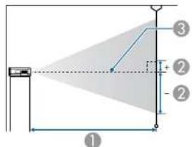
text_image
① ② ③
text_image
Diagram showing a geometric setup with labeled components and shaded triangular region, likely illustrating a physics or engineering concept.1 Projection distance
② is the distance from the center of the lens to the base of the screen. This changes depending on the setting for vertical lens shift.
③ Center of lens

If the screen is larger than 300 inches, fine text and images may not be displayed clearly.
ELPLM08
This section shows the projection distances for models equipped with standard lenses.
Unit: cm
| 4:3 Screen Size | 1 | 2 | |
| Minimum (Wide) to Maximum (Tele) | Vertical lens shift Bottom to Top | ||
| 50" 102x76 147 to 239 -82 to +6 | |||
| 60" 122x91 178 to 288 -98 to +7 | |||
| 80" 163x122 239 to 385 -131 to +9 | |||
| 100" 203x152 299 to 482 -164 to +12 | |||
| 120" 244x183 360 to 580 -197 to +14 | |||
| 150" 305x229 452 to 726 -246 to +17 | |||
| 200" 406x305 604 to 969 -328 to +23 | |||
| 250" 508x381 756 to 1213 -410 to +29 | |||
| 300" 610x457 908 to 1456 -492 to +35 | |||
| 500" 1016x762 | 1517 to 2430 | -820 to +58 | |
| 800" | 1626x1219 | 2431 to 3891 | -1312 to +93 |
| 1000" | 2032x1524 | 3040 to 4865 | -1640 to +116 |
Unit: cm
| 16:9 Screen Size | 1 | 2 |
| Minimum (Wide) to Maximum (Tele) | Vertical lens shift Bottom to Top | |
| 46" 102x57 148 to 240 -73 to +15 | ||
| 50" 111x62 161 to 261 -79 to +17 | ||
| 60" 133x75 194 to 314 -95 to +20 | ||
| 80" 177x100 260 to 420 -126 to +27 | ||
| 100" 221x125 327 to 526 -158 to +33 | ||
| 120" 266x149 393 to 632 -189 to +40 | ||
| 150" 332x187 493 to 791 -237 to +50 |
| 16:9 Screen Size | 1 | 2 | |
| Minimum (Wide) to Maximum (Tele) | Vertical lens shift Bottom to Top | ||
| 200" 443x | 249 658 to 1057 | -316 to +67 | |
| 250" 553x | 311 824 to 1322 | -395 to +83 | |
| 300" 664x | 374 990 to 1587 | -474 to +100 | |
| 500" 1107 | x623 1654 to 2648 | -789 to +167 | |
| 800" 1771 | x996 2649 to 4240 | -1263 to +267 | |
| 1000" 2214 | x1245 3312 to 5301 | -1579 to +334 | |
Unit: cm
| 16:10 Screen Size | 1 | 2 | |
| Minimum (Wide) to Maximum (Tele) | Vertical lens shift Bottom to Top | ||
| 48" 103x | 65 150 to 243 | -77 to +12 | |
| 50" 108x | 67 156 to 254 | -80 to +13 | |
| 60" 130x | 81 189 to 305 | -96 to +15 | |
| 80" | 172x108 | 253 to 408 | -128 to +21 |
| 100" 215x | 135 | 318 to 512 | -160 to +26 |
| 120" 258x | 162 | 382 to 615 | -192 to +31 |
| 150" 323x | 202 | 479 to 770 | -241 to +39 |
| 200" 431x | 269 640 to 1028 | 321 to +51 | |
| 250" 538x | 337 802 to 1286 | 401 to +64 | |
| 300" 646x | 404 963 to 1544 | 481 to +77 | |
| 500" 1077x | 673 1609 to 2576 | -802 to +129 | |
| 800" | 1723x1077 2577 | to 4125 -1283 to +206 | |
| 1000" 215x | 1x1346 3223 to 51 | 57 -1603 to +257 | |
ELPLX01/ELPLX01W
Zoom is not supported.
| 4:3 Screen Size | 1 | 2 | |
| Vertical lens shiftBottom to Top | |||
| 100" 203x152 | 71 | 0 to +12 | |
| 120" 244x183 | 86 | 0 to +14 | |
| 150" 305x229 | 109 | 0 to +17 | |
| 200" 406x305 | 147 | 0 to +23 | |
| 250" 508x381 | 185 | 0 to +29 | |
| 300" 610x457 | 223 | 0 to +35 | |
| 350" 711x533 | 261 | 0 to +40 | |
| 400" 813x610 | 299 | 0 to +46 | |
| 500" 1016x762 375 | 0 to +58 | ||
| 800" | 1626x1219 603 | 0 to +93 | |
| 1000" 203x1524 755 | 0 to +116 | ||
Unit: cm
| 16:9 Screen Size | 1 | 2 | |
| Vertical lens shiftBottom to Top | |||
| 92" | 204x115 | 71 | +19 to +31 |
| 100" 221x125 | 77 | +21 to +33 | |
| 120" 266x149 | 94 | +25 to +40 | |
| 150" 332x187 | 119 | +31 to +50 | |
| 200" 443x249 | 160 | +42 to +67 | |
| 250" 553x311 | 202 | +52 to +83 | |
| 300" 664x374 | 243 | +62 to +100 | |
| 350" 775x436 285 +73 to +117 | |||
| 500" 1107x623 409 +104 to +167 | |||
| 800" 1771x996 657 +166 to +267 | |||
Unit: cm
| 16:10 Screen Size | 1 | 2 | |
| Vertical lens shiftBottom to Top | |||
| 95" 205x | 128 71 +13 to +24 | ||
| 100" 215x | 135 75 +13 to +26 | ||
| 120" 258x | 162 91 +16 to +31 | ||
| 150" 323x | 202 116 +20 to +39 | ||
| 200" 431x | 269 156 +27 to +51 | ||
| 250" 538x | 337 196 +34 to +64 | ||
| 300" 646x | 404 236 +40 to +77 | ||
| 350" 754x | 471 277 +47 to +90 | ||
| 500" 1077x | 673 398 +67 to +129 | ||
| 800" 1723x | 1077 639 +108 to +206 | ||
ELPLU03
Unit: cm
| 4:3 Screen Size | 1 | 2 | |
| Minimum (Wide) to Maximum (Tele) | Vertical lens shift Bottom to Top | ||
| 80" 163x | 122 107 to 129 -131 to +9 | ||
| 4:3 Screen Size | 1 | 2 | |
| Minimum (Wide) to Maximum (Tele) | Vertical lens shift Bottom to Top | ||
| 100" 203x | 152 134 to 162 -1 | 64 to +12 | |
| 120" 244x | 183 162 to 196 -1 | 97 to +14 | |
| 150" 305x | 229 204 to 245 -2 | 46 to +17 | |
| 200" 406x | 305 273 to 328 -3 | 28 to +23 | |
| 250" 508x | 381 342 to 411 -4 | 10 to +29 | |
| 300" 610x | 457 411 to 494 -4 | 92 to +35 | |
| 500" 1016x | 762 | 687 to 826 -820 to +58 | |
| 800" 1626x | 1219 | 1101 to 1323 | -1312 to +93 |
| 1000" | 2032x1524 | 1377 to 1655 | -1640 to +116 |
Unit: cm
| 16:9 Screen Size | 1 | 2 | |
| Minimum (Wide) to Maximum (Tele) | Vertical lens shift Bottom to Top | ||
| 74" | 164x92 | 108 to 130 -117 to +25 | |
| 80" 177x | 100 117 to 141 -126 to +27 | ||
| 100" 221x | 125 147 to 177 -158 to +33 | ||
| 120" 266x | 149 177 to 213 -189 to +40 | ||
| 150" 332x | 187 222 to 268 -237 to +50 | ||
| 200" 443x | 249 297 to 358 -316 to +67 | ||
| 250" 553x | 311 373 to 448 -395 to +83 | ||
| 300" 664x | 374 448 to 539 -474 to +100 | ||
| 500" 1107x | 623 | 749 to 900 -789 to +167 | |
| 800" 1771x | 996 | 1200 to 1442 | -1263 to +267 |
Unit: cm
| 16:10 Screen Size | 1 | 2 | |
| Minimum (Wide) to Maximum (Tele) | Vertical lens shift Bottom to Top | ||
| 76" 164x | 102 108 to 130 -12 | 2 to +20 | |
| 80" 172x | 108 113 to 137 -12 | 8 to +21 | |
| 100" 215x | 135 143 to 172 -1 | 60 to +26 | |
| 120" 258x | 162 172 to 208 -1 | 92 to +31 | |
| 150" 323x | 202 216 to 260 -2 | 41 to +39 | |
| 200" 431x | 269 289 to 348 -3 | 21 to +51 | |
| 250" 538x | 337 362 to 436 -4 | 01 to +64 | |
| 300" 646x | 404 436 to 524 -4 | 81 to +77 | |
| 500" 1077 | x673 728 to 876 | 802 to +129 | |
| 800" 1723 | x1077 1168 to 14 | 03 -1283 to +206 | |
ELPLU04/ELPLU02
Unit: cm
| 4:3 Screen Size | 1 | 2 | |
| Minimum (Wide) to Maximum (Tele) | Vertical lens shift Bottom to Top | ||
| 50" 102x | 76 88 to 107 -82 to +6 | ||
| 60" 122x | 91 107 to 129 | -98 to +7 | |
| 80" 163x | 122 144 to 174 | -131 to +9 | |
| 100" 203x | 152 181 to 219 -164 to +12 | ||
| 120" 244x | 183 219 to 264 -197 to +14 | ||
| 150" 305x | 229 275 to 332 -246 to +17 | ||
| 200" 406x | 305 368 to 444 -328 to +23 | ||
| 250" 508x | 381 462 to 557 -410 to +29 | ||
| 4:3 Screen Size | 1 | 2 | |
| Minimum (Wide) to Maximum (Tele) | Vertical lens shift Bottom to Top | ||
| 300" 610x457 555 to 669 -492 to +35 | |||
| 500" 1016x762 | 929 to 1119 -820 to +58 | ||
| 800" 1626x1219 1490 to 1794 | -1312 to +93 | ||
| 1000" | 2032x1524 1864 to 2244 -1640 to +116 | ||
Unit: cm
| 16:9 Screen Size | 1 | 2 | |
| Minimum (Wide) to Maximum (Tele) | Vertical lens shift Bottom to Top | ||
| 46" 102x57 88 to 107 | -73 to +15 | ||
| 50" 111x62 96 to 117 | -79 to +17 | ||
| 60" 133x75 | 117 to 141 | -95 to +20 | |
| 80" 177x100 157 to 191 -126 to +27 | |||
| 100" 221x125 198 to 240 -158 to +33 | |||
| 120" 266x149 239 to 289 -189 to +40 | |||
| 150" 332x187 300 to 362 -237 to +50 | |||
| 200" 443x249 402 to 485 -316 to +67 | |||
| 250" 553x311 504 to 607 -395 to +83 | |||
| 300" 664x374 606 to 730 -474 to +100 | |||
| 500" 1107x623 | 1013 to 1220 | -789 to +167 | |
| 800" 1771x996 | 1624 to 1955 -1263 to +267 | ||
Unit: cm
| 16:10 Screen Size | 1 | 2 | |
| Minimum (Wide) to Maximum (Tele) | Vertical lens shift Bottom to Top | ||
| 48" 103x | 65 90 to 109 -77 to +12 | ||
| 50" 108x | 67 93 to 114 -80 to +13 | ||
| 60" 130x | 81 113 to 138 -96 to +15 | ||
| 80" 172x | 108 153 to 185 -128 to +21 | ||
| 100" 215x | 135 193 to 233 -160 to +26 | ||
| 120" 258x | 162 232 to 281 -192 to +31 | ||
| 150" 323x | 202 292 to 352 -241 to +39 | ||
| 200" 431x | 269 391 to 471 -321 to +51 | ||
| 250" 538x | 337 490 to 591 -401 to +64 | ||
| 300" 646x | 404 589 to 710 -481 to +77 | ||
| 500" 1077 | x673 985 to 1187 -802 to +129 | ||
| 800" 1723 | x1077 1580 to 1902 -1283 to +206 | ||
ELPLW05
Unit: cm
| 4:3 Screen Size | 1 | 2 | |
| Minimum (Wide) to Maximum (Tele) | Vertical lens shift Bottom to Top | ||
| 50" 102x | 76 104 to 149 -82 to +6 | ||
| 60" 122x | 91 127 to 180 -98 to +7 | ||
| 80" 163x | 122 171 to 242 -131 to +9 | ||
| 100" 203x | 152 216 to 303 -164 to +12 | ||
| 120" 244x | 183 261 to 365 -197 to +14 | ||
| 150" 305x | 229 328 to 458 -246 to +17 | ||
| 4:3 Screen Size | 1 | 2 | |
| Minimum (Wide) to Maximum (Tele) | Vertical lens shift Bottom to Top | ||
| 200" 406x | 305 440 to 612 -3 | 28 to +23 | |
| 250" 508x | 381 552 to 767 -4 | 10 to +29 | |
| 300" 610x | 457 664 to 922 -4 | 92 to +35 | |
| 500" 1016x | 762 | 112 to 1540 -820 to +58 | |
| 800" 1626x | 1219 | 1784 to 2467 | -1312 to +93 |
| 1000" | 2032x1524 | 2232 to 3086 | -1640 to +116 |
Unit: cm
| 16:9 Screen Size | 1 | 2 | |
| Minimum (Wide) to Maximum (Tele) | Vertical lens shift Bottom to Top | ||
| 46" 102x57 104 to 149 -73 to +15 | |||
| 50" 111x62 114 to 163 -79 to +17 | |||
| 60" 133x75 139 to 196 -95 to +20 | |||
| 80" 177x100 187 to 264 -126 to +27 | |||
| 100" 221x125 236 to 331 -158 to +33 | |||
| 120" 266x149 285 to 398 -189 to +40 | |||
| 150" 332x187 358 to 499 -237 to +50 | |||
| 200" 443x249 480 to 668 -316 to +67 | |||
| 250" 553x311 602 to 836 -395 to +83 | |||
| 300" 664x374 | 724 to 1005 -474 to +100 | ||
| 500" 1107x623 | 1212 to 1678 | -789 to +167 | |
| 800" 1771x996 | 1944 to 2689 | -1263 to +267 | |
Unit: cm
| 16:10 Screen Size | 1 | 2 | |
| Minimum (Wide) to Maximum (Tele) | Vertical lens shift Bottom to Top | ||
| 48" 103x | 65 106 to 151 -77 | to +12 | |
| 50" 108x | 67 111 to 158 -80 | to +13 | |
| 60" 130x | 81 135 to 191 -96 | to +15 | |
| 80" 172x | 108 182 to 256 -128 | to +21 | |
| 100" 215x | 135 230 to 322 -160 | to +26 | |
| 120" 258x | 162 277 to 387 -192 | to +31 | |
| 150" 323x | 202 348 to 486 -241 | to +39 | |
| 200" 431x | 269 467 to 650 -321 | to +51 | |
| 250" 538x | 337 586 to 813 -401 | to +64 | |
| 300" 646x | 404 704 to 977 -481 | to +77 | |
| 500" 1077 | x673 1179 to 1633 | -802 to +129 | |
| 800" 1723 | x1077 1891 to 2616 | -1283 to +206 | |
ELPLW06/ELPLW04
Unit: cm
| 4:3 Screen Size | 1 | 2 | |
| Minimum (Wide) to Maximum (Tele) | Vertical lens shift Bottom to Top | ||
| 50" 102x | 76 165 to 227 | -82 to +6 | |
| 60" 122x | 91 199 to 274 | -98 to +7 | |
| 80" 163x | 122 268 to 368 -131 to +9 | ||
| 100" 203x | 152 337 to 461 -164 to +12 | ||
| 120" 244x | 183 406 to 555 -197 to +14 | ||
| 150" 305x | 229 509 to 696 -246 to +17 | ||
| 4:3 Screen Size | 1 | 2 | |
| Minimum (Wide) to Maximum (Tele) | Vertical lens shift Bottom to Top | ||
| 200" 406x305 682 to 930 -328 to +23 | |||
| 250" 508x381 | 854 to 1164 | -410 to +29 | |
| 300" 610x457 | 1026 to 1398 | -492 to +35 | |
| 500" 1016x762 1715 to 2336 | -820 to +58 | ||
| 800" 1626x1219 2749 to 3741 -1312 to +93 | |||
| 1000" | 2032x1524 3438 to 4678 -1640 to +116 | ||
Unit: cm
| 16:9 Screen Size | 1 | 2 | |
| Minimum (Wide) to Maximum (Tele) | Vertical lens shift Bottom to Top | ||
| 46" 102x57 165 to 228 -73 to +15 | |||
| 50" 111x62 180 to 248 -79 to +17 | |||
| 60" 133x75 218 to 299 -95 to +20 | |||
| 80" 177x100 293 to 401 -126 to +27 | |||
| 100" 221x125 368 to 503 -158 to +33 | |||
| 120" 266x149 443 to 605 -189 to +40 | |||
| 150" 332x187 556 to 759 -237 to +50 | |||
| 200" 443x249 | 743 to 1014 | -316 to +67 | |
| 250" 553x311 | 931 to 1269 | -395 to +83 | |
| 300" 664x374 | 1119 to 1524 -474 to +100 | ||
| 500" 1107x623 1869 to 2545 -789 to +167 | |||
| 800" 1771x996 2995 to 4076 -1263 to +267 | |||
Unit: cm
| 16:10 Screen Size | 1 | 2 | |
| Minimum (Wide) to Maximum (Tele) | Vertical lens shift Bottom to Top | ||
| 48" 98x73 | 168 to 231 -77 to +12 | ||
| 50" 108x67 | 175 to 241 -80 to +13 | ||
| 60" 130x81 | 212 to 291 -96 to +15 | ||
| 80" 172x108 | 285 to 390 -128 to +21 | ||
| 100" 215x135 | 358 to 489 -160 to +26 | ||
| 120" 258x162 | 431 to 589 -192 to +31 | ||
| 150" 323x202 | 540 to 738 -241 to +39 | ||
| 200" 431x269 | 723 to 986 -321 to +51 | ||
| 250" 538x337 | 906 to 1234 -401 to +64 | ||
| 300" 646x404 | 1088 to 1483 -481 to +77 | ||
| 500" | 1077x673 | 1818 to 2476 | -802 to +129 |
| 800" | 1723x1077 | 2914 to 3966 | -1283 to +206 |
ELPLW08
Unit: cm
| 4:3 Screen Size | 1 | 2 | |
| Minimum (Wide) to Maximum (Tele) | Vertical lens shift Bottom to Top | ||
| 50" 102x | 76 120 to 169 | -82 to +6 | |
| 60" 122x | 91 145 to 204 | -98 to +7 | |
| 80" 163x | 122 194 to 273 -131 to +9 | ||
| 100" 203x | 152 244 to 343 -164 to +12 | ||
| 120" 244x | 183 294 to 413 -197 to +14 | ||
| 150" 305x | 229 368 to 517 -246 to +17 | ||
| 4:3 Screen Size | 1 | 2 | |
| Minimum (Wide) to Maximum (Tele) | Vertical lens shift Bottom to Top | ||
| 200" 406x | 305 493 to 692 -3 | 28 to +23 | |
| 250" 508x | 381 617 to 866 -4 | 10 to +29 | |
| 300" 610x | 457 741 to 1040 -4 | 92 to +35 | |
| 500" | 1016x762 | 1238 to 1737 -820 to +58 | |
| 800" | 1626x1219 | 1984 to 2782 | -1312 to +93 |
| 1000" | 2032x1524 | 2481 to 3479 | -1640 to +116 |
Unit: cm
| 16:9 Screen Size | 1 | 2 | |
| Minimum (Wide) to Maximum (Tele) | Vertical lens shift Bottom to Top | ||
| 46" 102x | 57 120 to 169 -73 to +15 | ||
| 60" 133x | 75 158 to 222 -95 to +20 | ||
| 80" 177x | 100 212 to 298 -126 to +27 | ||
| 100" 221x | 125 266 to 374 -158 to +33 | ||
| 120" 266x | 149 320 to 450 -189 to +40 | ||
| 150" 332x | 187 402 to 564 -237 to +50 | ||
| 200" 443x | 249 537 to 754 -316 to +67 | ||
| 250" 553x | 311 672 to 944 -395 to +83 | ||
| 300" 664x | 374 808 to 1134 -474 to +100 | ||
| 500" | 1107x623 | 1349 to 1893 | -789 to +167 |
| 800" | 1771x996 | 2162 to 3032 | -1263 to +267 |
Unit: cm
| 16:10 Screen Size | 1 | 2 | |
| Minimum (Wide) to Maximum (Tele) | Vertical lens shift Bottom to Top | ||
| 48" 103x | 65 122 to 172 -77 | to +12 | |
| 60" 130x | 81 154 to 216 -96 | to +15 | |
| 80" 172x | 108 206 to 290 -12 | 8 to +21 | |
| 100" 215x | 135 259 to 364 -1 | 60 to +26 | |
| 120" 258x | 162 312 to 438 -1 | 92 to +31 | |
| 150" 323x | 202 391 to 549 -2 | 41 to +39 | |
| 200" 431x | 269 522 to 733 -3 | 21 to +51 | |
| 250" 538x | 337 654 to 918 -4 | 01 to +64 | |
| 300" 646x | 404 786 to 1103 | 481 to +77 | |
| 500" 1077 | x673 1313 to 184 | -802 to +129 | |
| 800" 1723 | x1077 | 2103 to 2950 | -1283 to +206 |
ELPLM15/ELPLM09/ELPLS04
Unit: cm
| 4:3 Screen Size | 1 | 2 | |
| Minimum (Wide) to Maximum (Tele) | Vertical lens shift Bottom to Top | ||
| 50" 102x | 76 219 to 358 | -82 to +6 | |
| 60" 122x | 91 265 to 431 | -98 to +7 | |
| 80" 163x | 122 356 to 578 -131 to +9 | ||
| 100" 203x | 152 447 to 724 -164 to +12 | ||
| 120" 244x | 183 538 to 870 -197 to +14 | ||
| 150" 305x | 229 674 to 1090 -246 to +17 | ||
| 200" 406x | 305 902 to 1456 -328 to +23 | ||
| 4:3 Screen Size | 1 | 2 | |
| Minimum (Wide) to Maximum (Tele) | Vertical lens shift Bottom to Top | ||
| 250" 508x381 | 1 | 29 to 1822 | 410 to +29 |
| 300" 610x457 | 1 | 357 to 2188 | 492 to +35 |
| 500" 1016x762 2267 to 3652 | -820 to +58 | ||
| 800" 1626x1219 | 3632 to 5848 -1312 to +93 | ||
| 1000" | 2032x1524 | 4542 to 7312 | -1640 to +116 |
Unit: cm
| 16:9 Screen Size | 1 | 2 | |
| Minimum (Wide) to Maximum (Tele) | Vertical lens shift Bottom to Top | ||
| 46" 102x57 220 to 359 -73 to +15 | |||
| 50" 111x62 240 to 391 -79 to +17 | |||
| 60" 133x75 289 to 471 -95 to +20 | |||
| 80" 177x100 389 to 630 -126 to +27 | |||
| 100" 221x125 488 to 790 -158 to +33 | |||
| 120" 266x149 587 to 949 -189 to +40 | |||
| 150" 332x187 736 to 1188 -237 to +50 | |||
| 200" 443x249 983 to 1587 -316 to +67 | |||
| 250" 553x311 1231 to 1986 -395 to +83 | |||
| 300" 664x374 1479 to 2385 -474 to +100 | |||
| 500" 1107x623 2471 to 3980 -789 to +167 | |||
| 800" 1771x996 3958 to 6372 -1263 to +267 | |||
Unit: cm
| 16:10 Screen Size | 1 | 2 | |
| Minimum (Wide) to Maximum (Tele) | Vertical lens shift Bottom to Top | ||
| 48" 103x | 65 223 to 364 -77 | to +12 | |
| 50" 108x | 67 233 to 380 -80 | to +13 | |
| 60" 130x | 81 281 to 458 -96 | to +15 | |
| 80" 172x | 108 378 to 613 -128 | to +21 | |
| 100" 215x | 135 474 to 768 -160 | to +26 | |
| 120" 258x | 162 571 to 923 -192 | to +31 | |
| 150" 323x | 202 715 to 1156 -241 | to +39 | |
| 200" 431x | 269 957 to 1544 -321 | to +51 | |
| 250" 538x | 337 1198 to 1932 -401 | to +64 | |
| 300" 646x | 404 1439 to 2320 -481 | to +77 | |
| 500" 1077 | x673 2403 to 3872 | -802 to +129 | |
| 800" | 1723x1077 | 3850 to 6199 | -1283 to +206 |
ELPLM10/ELPLM06
Unit: cm
| 4:3 Screen Size | 1 | 2 | |
| Minimum (Wide) to Maximum (Tele) | Vertical lens shift Bottom to Top | ||
| 50" 102x | 76 338 to 519 | -82 to +6 | |
| 60" 122x | 91 409 to 625 | -98 to +7 | |
| 80" 163x | 122 549 to 838 -131 to +9 | ||
| 100" 203x | 152 690 to 1051 -164 to +12 | ||
| 120" 244x | 183 831 to 1264 -197 to +14 | ||
| 150" 305x | 229 1041 to 1583 -246 to +17 | ||
| 4:3 Screen Size | 1 | 2 | |
| Minimum (Wide) to Maximum (Tele) | Vertical lens shift Bottom to Top | ||
| 200" 406x | 305 1393 to 2115 | -328 to +23 | |
| 250" 508x | 381 1744 to 2647 | -410 to +29 | |
| 300" 610x | 457 2096 to 3179 | -492 to +35 | |
| 500" 1016x | 762 3502 to 5307 | -820 to +58 | |
| 800" | 1626x1219 | 5611 to 8499 | -1312 to +93 |
| 1000" | 2032x1524 | 7017 to 10627 | -1640 to +116 |
Unit: cm
| 16:9 Screen Size | 1 | 2 | |
| Minimum (Wide) to Maximum (Tele) | Vertical lens shift Bottom to Top | ||
| 46" 102x57 339 to 520 -73 to +15 | |||
| 50" 111x62 370 to 567 -79 to +17 | |||
| 60" 133x75 446 to 682 -95 to +20 | |||
| 80" 177x100 600 to 914 -126 to +27 | |||
| 100" 221x125 753 to 1146 -158 to +33 | |||
| 120" 266x149 906 to 1378 -189 to +40 | |||
| 150" 332x187 1136 to 1726 -237 to +50 | |||
| 200" 443x249 1519 to 2305 -316 to +67 | |||
| 250" 553x311 1902 to 2885 -395 to +83 | |||
| 300" 664x374 2285 to 3465 | -474 to +100 | ||
| 500" 1107x623 3816 to 5783 | -789 to +167 | ||
| 800" 1771x996 6114 to 9261 | -1263 to +267 | ||
Unit: cm
| 16:10 Screen Size | 1 | 2 | |
| Minimum (Wide) to Maximum (Tele) | Vertical lens shift Bottom to Top | ||
| 48" 103x | 65 345 to 528 -77 | to +12 | |
| 50" 108x | 67 360 to 551 -80 | to +13 | |
| 60" 130x | 81 434 to 664 -96 | to +15 | |
| 80" 172x | 108 583 to 889 -128 | to +21 | |
| 100" 215x | 135 732 to 1115 | -160 to +26 | |
| 120" 258x | 162 881 to 1340 | -192 to +31 | |
| 150" 323x | 202 1105 to 1679 | -241 to +39 | |
| 200" 431x | 269 1477 to 2243 | -321 to +51 | |
| 250" 538x | 337 1850 to 2807 | -401 to +64 | |
| 300" 646x | 404 2222 to 3370 | -481 to +77 | |
| 500" 1077 | x673 3713 to 5626 | -802 to +129 | |
| 800" | 1723x1077 | 5948 to 9010 | -1283 to +206 |
ELPLM11/ELPLM07
Unit: cm
| 4:3 Screen Size | 1 | 2 | |
| Minimum (Wide) to Maximum (Tele) | Vertical lens shift Bottom to Top | ||
| 50" 102x | 76 492 to 755 | -82 to +6 | |
| 60" 122x | 91 595 to 910 | -98 to +7 | |
| 80" 163x | 122 801 to 1221 | -131 to +9 | |
| 100" 203x | 152 1007 to 1533 | -164 to +12 | |
| 120" 244x | 183 1213 to 1844 | -197 to +14 | |
| 150" 305x | 229 1523 to 2311 | -246 to +17 | |
| 4:3 Screen Size | 1 | 2 | |
| Minimum (Wide) to Maximum (Tele) | Vertical lens shift Bottom to Top | ||
| 200" 406x | 305 2038 to 3089 | -328 to +23 | |
| 250" 508x | 381 2554 to 3867 | -410 to +29 | |
| 300" 610x | 457 3069 to 4645 | -492 to +35 | |
| 500" 1016x | 762 5131 to 7757 | -820 to +58 | |
| 800" | 1626x1219 | 8224 to 12425 | -1312 to +93 |
| 1000" | 2032x1524 | 10286 to 15537 | -1640 to +116 |
Unit: cm
| 16:9 Screen Size | 1 | 2 | |
| Minimum (Wide) to Maximum (Tele) | Vertical lens shift Bottom to Top | ||
| 46" 102x57 493 to 756 -73 to +15 | |||
| 50" 111x62 538 to 824 -79 to +17 | |||
| 60" 133x75 650 to 994 -95 to +20 | |||
| 80" 177x100 875 to 1333 -126 to +27 | |||
| 100" 221x125 1100 to 1672 -158 to +33 | |||
| 120" 266x149 1324 to 2011 -189 to +40 | |||
| 150" 332x187 1661 to 2519 -237 to +50 | |||
| 200" 443x249 2223 to 3367 -316 to +67 | |||
| 250" 553x311 2784 to 4215 -395 to +83 | |||
| 300" 664x374 3346 to 5062 -474 to +100 | |||
| 500" 1107x623 5592 to 8453 -789 to +167 | |||
| 800" 1771x996 8962 to 13538 -1263 to +267 | |||
Unit: cm
| 16:10 Screen Size | 1 | 2 | |
| Minimum (Wide) to Maximum (Tele) | Vertical lens shift Bottom to Top | ||
| 48" 103x | 65 501 to 768 -77 | to +12 | |
| 50" 108x | 67 523 to 801 -80 | to +13 | |
| 60" 130x | 81 632 to 966 -96 | to +15 | |
| 80" 172x | 108 851 to 1296 - | 128 to +21 | |
| 100" 215x | 135 1069 to 1626 | -160 to +26 | |
| 120" 258x | 162 1288 to 1956 | -192 to +31 | |
| 150" 323x | 202 1616 to 2451 | -241 to +39 | |
| 200" 431x | 269 2162 to 3275 | -321 to +51 | |
| 250" 538x | 337 2708 to 4100 | -401 to +64 | |
| 300" 646x | 404 3255 to 4925 | -481 to +77 | |
| 500" 1077 | x673 5441 to 822 | -802 to +129 | |
| 800" 1723 | x1077 | 8719 to 13171 | -1283 to +206 |
ELPLL08/ELPLL07
Unit: cm
| 4:3 Screen Size | 1 | 2 | ||
| Minimum (Wide) to Maximum (Tele) | Vertical lens shift Bottom to Top | |||
| 50" 102x | 76 | 732 to 1034 -82 to +6 | ||
| 60" 122x | 91 | 885 to 1247 -98 to +7 | ||
| 80" 163x | 122 | 1191 to 1674 -131 to +9 | ||
| 100" 203x | 152 | 1497 to 2100 -164 to +12 | ||
| 120" 244x | 183 | 1802 to 2527 -197 to +14 | ||
| 150" 305x | 229 | 2261 to 3166 -246 to +17 | ||
| 4:3 Screen Size | 1 | 2 | |
| Minimum (Wide) to Maximum (Tele) | Vertical lens shift Bottom to Top | ||
| 200" 406x | 305 3025 to 4232 | -328 to +23 | |
| 250" 508x | 381 3790 to 5298 | -410 to +29 | |
| 300" 610x | 457 4554 to 6364 | -492 to +35 | |
| 500" 1016x | 762 | 7611 to 10627 -820 to +58 | |
| 800" 1626x | 1219 | 12197 to 17023 | -1312 to +93 |
| 1000" | 2032x1524 | 15255 to 21287 | -1640 to +116 |
Unit: cm
| 16:9 Screen Size | 1 | 2 | |
| Minimum (Wide) to Maximum (Tele) | Vertical lens shift Bottom to Top | ||
| 46" 102x57 | 734 to 1037 | -73 to +15 | |
| 50" 111x62 | 801 to 1130 | -79 to +17 | |
| 60" 133x75 | 967 to 1362 | -95 to +20 | |
| 80" 177x100 | 1300 to 1826 | -126 to +27 | |
| 100" 221x125 | 1633 to 2291 | -158 to +33 | |
| 120" 266x149 | 1967 to 2755 | -189 to +40 | |
| 150" 332x187 | 2466 to 3452 | -237 to +50 | |
| 200" 443x249 | 3299 to 4613 | -316 to +67 | |
| 250" 553x311 | 4132 to 5775 | -395 to +83 | |
| 300" 664x374 | 4964 to 6939 | -474 to +100 | |
| 500" 1107x623 | 8295 to 11581 | -789 to +167 | |
| 800" 1771x996 | 13292 to 18549 | -1263 to +267 | |
Unit: cm
| 16:10 Screen Size | 1 | 2 | |
| Minimum (Wide) to Maximum (Tele) | Vertical lens shift Bottom to Top | ||
| 48" 103x | 65 746 to 1053 -77 to +12 | ||
| 50" 108x | 67 778 to 1098 -80 to +13 | ||
| 60" 130x | 81 940 to 1324 -96 to +15 | ||
| 80" 172x | 108 1264 to 1776 -128 to +21 | ||
| 100" 215x | 135 1588 to 2228 -160 to +26 | ||
| 120" 258x | 162 1913 to 2680 -192 to +31 | ||
| 150" 323x | 202 2399 to 3358 -241 to +39 | ||
| 200" 431x | 269 3209 to 4488 -321 to +51 | ||
| 250" 538x | 337 4019 to 5618 -401 to +64 | ||
| 300" 646x | 404 4829 to 6748 -481 to +77 | ||
| 500" 1077 | x673 8070 to 11267 -802 to +129 | ||
| 800" 1723 | x1077 12931 to 18046 -1283 to +206 | ||
ELPLR04
Zoom and lens shift are not supported.
Unit: cm
| 4:3 Screen Size | 1 | 2 | |
| 50" | 102x76 | 96 | -38 |
| 60" | 122x91 | 116 | -46 |
| 80" | 163x122 | 157 | -61 |
| 100" | 203x152 | 198 | -76 |
| 120" | 244x183 | 239 | -91 |
| 150" | 305x229 | 300 | -114 |
| 4:3 Screen Size | 1 | 2 | |
| 200" | 406x305 | 402 | -152 |
| 250" | 508x381 | 504 | -191 |
| 300" | 610x457 | 606 | -229 |
| 500" | 1016x762 | 1015 | -381 |
| 800" | 1626x1219 | 1627 | -610 |
| 1000" | 2032x1524 | 2035 | -762 |
Unit: cm
| 16:9 Screen Size | 1 | 2 | |
| 46" | 102x57 | 96 | -29 |
| 50" | 111x62 | 105 | -31 |
| 60" | 133x75 | 127 | -37 |
| 80" | 177x100 | 172 | -50 |
| 100" | 221x125 | 216 | -62 |
| 120" | 266x149 | 261 | -75 |
| 150" | 332x187 | 327 | -93 |
| 200" | 443x249 | 439 | -125 |
| 250" | 553x311 | 550 | -156 |
| 300" | 664x374 | 661 | -187 |
| 500" | 1107x623 | 1106 | -311 |
| 800" | 1771x996 | 1773 | -498 |
Unit: cm
| 16:10 Screen Size | 1 | 2 | |
| 48" | 103x65 | 98 | -32 |
| 50" | 108x67 | 102 | -34 |
| 60" | 130x81 | 124 | -40 |
| 16:10 Screen Size | 1 | 2 |
| 80" 172x108 167 -54 | ||
| 100" 215x135 210 -67 | ||
| 120" 258x162 254 -81 | ||
| 150" 323x202 318 -101 | ||
| 200" 431x269 427 -135 | ||
| 250" 538x337 535 -168 | ||
| 300" 646x404 643 -202 | ||
| 500" 1077x673 1076 -337 | ||
| 800" 1723x1077 1725 -538 |
Polarizer (ELPPL01) Installation Distance

text_image
① ② ③ ④① Possible installation range of the polarizer
② Shortest distance from the projection lens to the polarizer
③ Longest distance from the projection lens to the polarizer
4 Polarizer (EI.PPI.01)
EB-L1075U/EB-L1070U/EB-L1065U/EB-L1060U/EB-L1050U
Units: mm
| Lens type | 1 | |
| 2 | 3 | |
| ELPLM08 140 170 | ||
| ELPLW06/ELPLW04 120 170 | ||
| ELPLW08 100 130 | ||
| ELPLM15/ELPLM09/ELPLS04 | 180 240 | |
| ELPLM10/ELPLM06 | 260 340 | |
EB-L1070W/EB-L1060W
Units: mm
| Lens type | 1 | |
| 2 | 3 | |
| ELPLM08 150 170 | ||
| ELPLW06/ELPLW04 120 170 | ||
| ELPLW08 100 130 | ||
| ELPLM15/ELPLM09/ELPLS04 | 200 240 | |
| ELPLM10/ELPLM06 | 300 340 | |
EB-L1070
Units: mm
| Lens type | 1 | |
| 2 | 3 | |
| ELPLM08 130 170 | ||
| ELPLW06/ELPLW04 120 170 | ||
Screen Size and Projection Distance

260
| Lens type | 1 | |
| 2 | 3 | |
| ELPLW08 100 130 | ||
| ELPLM15/ELPLM09/ELPLS04 | 170 240 | |
| ELPLM10/ELPLM06 230 | 340 | |
Adjustment Range for Projected Images

H/V-Keystone
"H/V-Keystone" p.65
| Lens type Vertical Horizontal | |
| ELPLM08 -45° to 45° -30° to 30° | |
| ELPLX01/ELPLX01W -16° to 16° -16° to 16° | |
| ELPLU03 -28° to 28° -28° to 28° | |
| ELPLU04/ELPLU02 -35° to 35° -30° to 30° | |
| ELPLR04 -34° to 34° -30° to 30° | |
| ELPLW05 -40° to 40° -30° to 30° | |
| ELPLW06/ELPLW04 -45° to 45° -30° to 30° | |
| ELPLW08 -40° to 40° -30° to 30° | |
| ELPLM15/ELPLM09/ELPLS04 | -45° to 45° -30° to 30° |
| ELPLM10/ELPLM06 -45° to 45° -30° to 30° | |
| ELPLM11/ELPLM07 -45° to 45° -30° to 30° | |
| ELPLL08/ELPLL07 -45° to 45° -30° to 30° |
Curved Surface
"Curved Surface" p.67
The values in the table are the minimum values for R/L in the illustration. (Approximate value when projecting at maximum zoom. ELPLR04 does not support lens shift.)
EB-L1075U/EB-L1070U/EB-L1065U/EB-L1060U/EB-L1050U/EB-L1070W/EB-L1060W
Horizontally curved surface (concave)
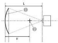
1 Screen
② Center of the circle of which the curved surface is an arc
L Projection distance
R Radius of the circle of which the curved surface is an arc
Top view
Lens type Vertical lens shift: 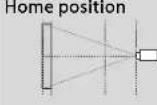 Side view Side view | Vertical lens shift: Top  Side view Side view | |
| ELPLM08 | 0.29 | 0.30 |
| ELPLX01/ELPLX01W - | 2.74 | |
| ELPLU03 | 0.45 | 0.56 |
| ELPLU04/ELPLU02 | 0.39 | 0.40 |
| ELPLR04 | 0.37 | - |
| ELPLW05 | 0.35 | 0.37 |
| ELPLW06/ELPLW04 | 0.26 | 0.27 |
| ELPLW08 | 0.33 | 0.34 |
| ELPI.M15/ELPI.M09/ ELPLS04 | 0.21 | 0.22 |
| ELPLM10/ELPLM06 | 0.15 | 0.15 |
Adjustment Range for Projected Images

262
Lens type Vertical lens shift:Home position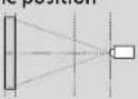 Side view Side view | Vertical lens shift: Top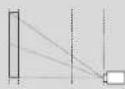 Side view Side view |
| ELPLM11/ELPLM07 0.11 0.11 | |
| ELPLL08/ELPLL07 0.08 0.08 |
Horizontally curved surface (convex)

Screen
② Center of the circle of which the curved surface is an arc
I. Projection distance
R Radius of the circle of which the curved surface is an arc
Top view
Lens type Vertical lens shift:Home position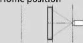 Side view Side view | Vertical lens shift: Top Side view Side view | |
| ELPLM08 0.58 0.62 | ||
| ELPLX01/ELPLX01W - 3.52 | ||
| ELPLU03 2.13 2.31 | ||
| ELPLU04/ELPLU02 | 1.27 1.37 | |
| ELPLR04 | 1.10 - | |
| ELPLW05 | 0.95 1.01 | |
| ELPLW06/ELPLW04 | 0.49 0.52 | |
| ELPLW08 | 0.79 0.84 | |
| ELPLM15/ELPLM09/ELPLS04 | 0.33 0.35 | |
| ELPLM10/ELPLM06 | 0.20 0.20 | |
| ELPLM11/ELPLM07 | 0.13 0.13 | |
| ELPLL08/ELPLL07 | 0.09 0.09 | |
Adjustment Range for Projected Images

Vertically curved surface (concave)

1 Screen
② Center of the circle of which the curved surface is an arc
I. Projection distance
R Radius of the circle of which the curved surface is an arc
Side view
Lens type Vertical lens shift:Home position Side view Side view | Vertical lens shift: Top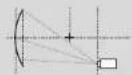 Side view Side view |
| ELPLL08/ELPLL07 | 0.06 0.06 |
Lens type Vertical lens shift:Home position Side view Side view | Vertical lens shift: Top Side view Side view | |
| ELPLM08 0.21 0.25 | ||
| ELPLX01/ELPLX01W - 1.98 | ||
| ELPLU03 0.37 0.67 | ||
| ELPLU04/ELPLU02 0.31 0.43 | ||
| ELPLR04 0.29 | ||
| ELPLW05 0.27 0.35 | ||
| ELPLW06/ELPLW04 0.19 0.22 | ||
| ELPLW08 0.25 0.31 | ||
| ELPLM15/ELPLM09/ELPLS04 | 0.15 0.17 | |
| ELPLM10/ELPLM06 | 0.11 0.11 | |
| ELPLM11/ELPLM07 | 0.08 0.08 | |
Vertically curved surface (convex)

① Screen
② Center of the circle of which the curved surface is an arc
I. Projection distance
R Radius of the circle of which the curved surface is an arc
Side view
Lens type Vertical lens shift:Home position Side view Side view | Vertical lens shift: Top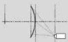 Side view Side view |
| ELPLL08/ELPLL07 | 0.06 0.06 |
Lens type Vertical lens shift:Home position Side view Side view | Vertical lens shift: Top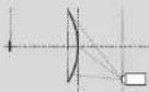 Side view Side view | |
| ELPLM08 0.31 0.37 | ||
| ELPLX01/ELPLX01W - 3.52 | ||
| ELPLU03 1.07 1.29 | ||
| ELPLU04/ELPLU02 0.65 0.79 | ||
| ELPLR04 0.57 | ||
| ELPLW05 0.49 0.59 | ||
| ELPLW06/ELPLW04 0.26 0.32 | ||
| ELPLW08 0.42 0.50 | ||
| ELPLM15/ELPLM09/ELPLS04 | 0.18 0.22 | |
| ELPLM10/ELPLM06 | 0.12 0.13 | |
| ELPLM11/ELPLM07 | 0.08 0.09 | |
Adjustment Range for Projected Images

EB-L1070
Horizontally curved surface (concave)

① Screen
② Center of the circle of which the curved surface is an arc
L Projection distance
R Radius of the circle of which the curved surface is an arc
Top view
Lens type Vertical lens shift:Home position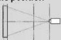 Side view Side view | Vertical lens shift: Top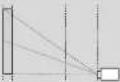 Side view Side view | |
| ELPLM08 0.27 0.27 | ||
| ELPLX01/ELPLX01W - 1.66 | ||
| ELPLU03 0.44 0.60 | ||
| ELPLU04/ELPLU02 0.37 0.40 | ||
| ELPLR04 0.35 - | ||
| ELPLW05 0.33 0.34 | ||
| ELPLW06/ELPLW04 0.25 0.25 | ||
| ELPLW08 0.31 0.32 | ||
| ELPLM15/ELPLM09/ELPLS04 | 0.20 0.20 | |
| ELPLM10/ELPLM06 | 0.14 0.14 | |
| ELPLM11/ELPLM07 | 0.11 0.11 | |
Horizontally curved surface (convex)
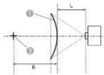
Top view
1 Screen
② Center of the circle of which the curved surface is an arc
I. Projection distance
R Radius of the circle of which the curved surface is an arc
Vertically curved surface (concave)

Side view
Screen
② Center of the circle of which the curved surface is an arc
I. Projection distance
R Radius of the circle of which the curved surface is an arc
Lens type Vertical lens shift:Home position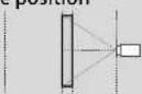 Side view Side view | Vertical lens shift: Top Side view Side view | |
| ELPLM08 0.52 0.54 | ||
| FLPLX01/ELPLX01W - 3.52 | ||
| ELPLU03 1.81 1.88 | ||
| ELPLU04/ELPLU02 1.10 1.14 | ||
| ELPLR04 0.95 - | ||
| ELPLW05 0.83 0.86 | ||
| FLPLW06/ELPLW04 0.44 0.45 | ||
| ELPLW08 0.70 0.72 | ||
| ELPLM15/ELPLM09/FLPLS04 | 0.31 0.31 | |
| ELPLM10/ELPLM06 | 0.19 0.19 | |
| ELPLM11/ELPLM07 | 0.13 0.13 | |
| ELPLL08/ELPLL07 | 0.09 0.09 | |
Lens type Vertical lens shift:Home position Side view Side view | Vertical lens shift: Top Side view Side view | |
| ELPLM08 0.22 0.28 | ||
| ELPLX01/ELPLX01W - 1.73 | ||
| ELPLU03 0.37 0.65 | ||
| ELPLU04/ELPLU02 0.32 | 0.46 | |
| ELPLR04 | -0.30 | |
| ELPLW05 0.28 | 0.38 | |
| ELPLW06/ELPLW04 0.20 | 0.25 | |
| ELPLW08 0.26 | 0.34 | |
| ELPLM15/ELPLM09/ELPLS04 | 0.16 | 0.19 |
| ELPLM10/ELPLM06 | 0.11 | 0.13 |
| ELPLM11/ELPLM07 | 0.08 | 0.09 |
Adjustment Range for Projected Images

Lens type Vertical lens shift:Home position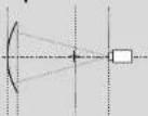 Side view Side view | Vertical lens shift: Top Side view Side view |
| ELPLL08/ELPLL07 0.06 0.07 |
Vertically curved surface (convex)
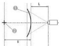
Screen
② Center of the circle of which the curved surface is an arc
I. Projection distance
R Radius of the circle of which the curved surface is an arc
Side view
Lens type Vertical lens shift:Home position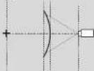 Side view Side view | Vertical lens shift: Top Side view Side view | |
| ELPLM08 0.34 0.44 | ||
| ELPLX01/ELPLX01W - 3.52 | ||
| ELPLU03 1.08 1.57 | ||
| ELPLU04/ELPLU02 0.66 0.94 | ||
| ELPLR04 0.57 - | ||
| ELPLW05 0.50 0.71 | ||
| ELPLW06/ELPLW04 | 0.29 0.37 | |
| ELPLW08 0.43 0.59 | ||
| ELPLM15/ELPLM09/ELPLS04 | 0.21 0.26 | |
| ELPLM10/ELPLM06 | 0.14 0.15 | |
| ELPLM11/ELPLM07 | 0.10 0.10 | |
Adjustment Range for Projected Images

268
Lens type Vertical lens shift:Home position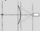 Side view Side view | Vertical lens shift: Top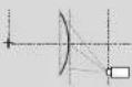 Side view Side view |
| ELPLL08/ELPLL07 0.07 0.07 |
Corner Wall
"Corner Wall" p.71
The in the figure is the maximum angle in which the projector can move. See the table below for detailed values. (Approximate value when projecting at maximum zoom. ELPLR04 does not support lens shift.)
EB-L1075U/EB-L1070U/EB-L1065U/EB-L1060U/EB-L1050U/EB-L1070W/EB-L1060W
Concave horizontal corner correction (correction to bilateral symmetry by using corners as the center line)

1 Screen
a Angle of possible projector motion
Top view
| Lens type Vertical lens shift: | Vertical lens shift: Top | |
Hom 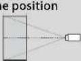 Side view Side view |  Side view Side view | |
| ELPLM08 31° 23° | ||
| ELPLX01/ELPLX01W - - | ||
| ELPLU03 29° 9" | ||
| ELPLU04/ELPLU02 31° 14" | ||
| ELPLR04 | 32° | - |
| ELPLW05 | 33° 18° | |
| ELPLW06/ELPLW04 | 31° 25° | |
| ELPLW08 | 32° 20° | |
| ELPLM15/ELPLM09/ ELPLS04 | 30° 29° | |
| ELPLM10/ELPLM06 29° 29° | ||
Adjustment Range for Projected Images

Lens type Vertical lens shift:Home position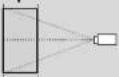 Side view Side view | Vertical lens shift: Top Side view Side view |
| ELPLM11/ELPLM07 29° 28° | |
| ELPLL08/ELPLL07 28° 28° |
Convex horizontal corner correction (correction to bilateral symmetry by using corners as the center line)

Top view
① Screen
α Angle of possible projector motion
| Lens type Vertical lens | shift:Home position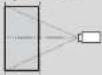 Side view Side view | Vertical lens shift: Top  Side view Side view |
| ELPLM08 14' 13' | ||
| ELPLX01/ELPLX01W -- | ||
| ELPLU03 0° * | ||
| ELPLU04/ELPLU02 6' 4' |
| Lens type Vertical lens | shift:Home position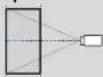 Side view Side view | Vertical lens shift: Top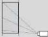 Side view Side view |
| ELPLR04 | 8° | |
| ELPLW05 | 9° 8° | |
| ELPLW06/ELPLW04 | 16° 15° | |
| ELPLW08 | 11° 10° | |
| ELPLM15/ELPLM09/ELPLS04 | 18° 18° | |
| ELPLM10/ELPLM06 22° 21° | ||
| ELPLM11/ELPLM07 23° 23° | ||
| ELPLL08/ELPLL07 24° | 24° |
*Cannot be corrected accurately. Move the lens position to the home position.
Concave vertical corner correction (correction to horizontal symmetry by using corners as the center line)

1 Screen
a Angle of possible projector motion
Side view
| Lens type Vertical lens | shift: Hom 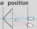 Side view Side view | Vertical lens shift: Top  Side view Side view |
| ELPLM08 30° 12' | ||
| ELPLX01/ELPLX01W - - | ||
| ELPLU03 33° * | ||
| ELPLU04/ELPLU02 31° 6' | ||
| ELPLR04 31° - | ||
| ELPLW05 | 31° 10° | |
| ELPLW06/ELPLW04 | 28° 13° | |
| ELPLW08 | 31° 11° | |
| ELPLM15/ELPLM09/ ELPLS04 | 26° | 14° |
| ELPLM10/ELPLM06 24' | 16° | |
| ELPLM11/ELPLM07 23° | 18° | |
| ELPLL08/ELPLL07 | 23° 19° |
^* Cannot be corrected accurately. Move the lens position to the home position.
Convex vertical corner correction (correction to horizontal symmetry by using corners as the center line)

① Screen
α Angle of possible projector motion
Side view
| Lens type Vertical lens | shift:Home position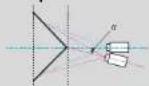 Side view Side view | Vertical lens shift: Top Side view Side view |
| ELPLM08 19° 5° | ||
| ELPLX01/ELPLX01W - - | ||
| ELPLU03 | 9° | * |
| ELPLU04/ELPLU02 14° * | ||
| ELPLR04 15° - | ||
| ELPLW05 | 16° * | |
| ELPLW06/ELPLW04 | 20° 7° | |
| ELPLW08 | 17° 1° | |
| ELPLM15/ELPLM09/ELPLS04 | 22° | 12° |
| ELPLM10/ELPLM06 22° | 15° | |
| ELPLM11/ELPLM07 22° | 17° | |
| ELPLL08/ELPLL07 | 22° | 18° |
*Cannot be corrected accurately. Move the lens position to the home position.
EB-L1070
Concave horizontal corner correction (correction to bilateral symmetry by using corners as the center line)


Screen
α Angle of possible projector motion
Top view
Lens type Vertical lens shift:Home position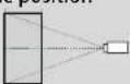 Side view Side view | Vertical lens shift: Top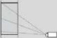 Side view Side view | |
| ELPLM08 31° 21' | ||
| ELPLX01/ELPLX01W - - | ||
| ELPLU03 26° 7' | ||
| ELPLU04/ELPLU02 29° 13' | ||
| ELPLR04 30° - | ||
| ELPLW05 31° 16' | ||
| ELPLW06/ELPLW04 31° 23" | ||
| ELPLW08 32° 18' | ||
| ELPLM15/ELPLM09/ELPLS04 | 30° | 27° |
| ELPLM10/ELPLM06 29' | 29° | |
| ELPLM11/ELPLM07 29' | 29° | |
Lens type Vertical lens shift:Home position Side view Side view | Vertical lens shift: Top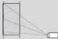 Side view Side view |
| ELPLL08/ELPLL07 | 28' |
Convex horizontal corner correction (correction to bilateral symmetry by using corners as the center line)
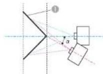

Screen
a Angle of possible projector motion
Top view
| Lens type | Vertical lens shift: Home position Side view Side view | Vertical lens shift: Top Side view Side view |
| ELPLM08 14° | 14" | |
| ELPLX01/ELPLX01W -- | ||
| ELPLU03 | 0° | * |
| ELPLU04/ELPLU02 | 6° | 2° |
| ELPLR04 | 8° | - |
Adjustment Range for Projected Images

| Lens type Vertical lens | shift:Home position Side view Side view | Vertical lens shift: Top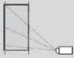 Side view Side view |
| ELPLW05 10° 7° | ||
| ELPLW06/ELPLW04 16° 16° | ||
| ELPLW08 12° 10° | ||
| ELPLM15/ELPLM09/ELPLS04 | 19° 18° | |
| ELPLM10/ELPLM06 22° 21° | ||
| ELPLM11/ELPLM07 23° 23° | ||
| ELPLL08/ELPLL07 24° 24° |
*Cannot be corrected accurately. Move the lens position to the home position.
Concave vertical corner correction (correction to horizontal symmetry by using corners as the center line)

Side view
① Screen
α Angle of possible projector motion
| Lens type Vertical lens | shift:Home position Side view Side view | Vertical lens shift: Top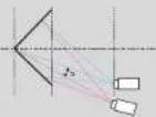 Side view Side view |
| ELPLM08 31° 14° | ||
| ELPLX01/ELPLX01W - | - | |
| ELPLU03 | 33° | * |
| ELPLU04/ELPLU02 | 32° 7° | |
| ELPLR04 | 32° | - |
| ELPI.W05 31° 10° | ||
| ELPLW06/ELPLW04 | 30° 16° | |
| ELPI.W08 31° 12° | ||
| ELPI.M15/ELPI.M09/ELPLS04 | 29° 17° | |
| ELPLM10/ELPLM06 27° 19° | ||
| ELPLM11/ELPLM07 26° 21° | ||
| ELPLL08/ELPLL07 26° 22° |
*Cannot be corrected accurately. Move the lens position to the home position.
Convex vertical corner correction (correction to horizontal symmetry by using corners as the center line)

1 Screen
a Angle of possible projector motion
Side view
| Lens type Vertical lens | shift:Home position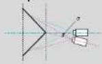 Side view Side view | Vertical lens shift: Top Side view Side view |
| ELPLM08 18° 4° | ||
| ELPLX01/ELPLX01W - - | ||
| ELPLU03 6° * | ||
| ELPLU04/ELPLU02 12° * | ||
| ELPLR04 13° - | ||
| ELPLW05 | 14° * | |
| ELPLW06/ELPLW04 | 19° 6° | |
| ELPLW08 | 16° 0° | |
| ELPLM15/ELPLM09/ELPLS04 | 21° | 11° |
| ELPLM10/ELPLM06 23° | 16° | |
| ELPLM11/ELPLM07 24° | 19° | |
| ELPLL08/ELPLL07 | 25° | 21" |
*Cannot be corrected accurately. Move the lens position to the home position.
Supported Monitor Displays
When the resolution of the input signals is larger than the projector's panel resolution, the image quality may decline. Signals with a check mark are supported.
PC
| Signal Format | Resolution (Dot) | V Sync (Hz) | Computer/BNC HDMI/HDBaseT DVI-D | ||||||||||||||||||
| RGB YCbCr RGB YCbCr RGB YCbCr | |||||||||||||||||||||
| 4:4:4 4:2:2 4:2:0 4:4:4 4:2:2 | |||||||||||||||||||||
| 8 | 10 | 12 | 8 | 10 | 12 | 8 | 10 | 12 | 8 | 10 | 12 | 8 | 8 | 8 | |||||||
| VGA | 640 | 480 | 60 | ✓ | ✓ | ✓ | |||||||||||||||
| 72 | ✓ | ||||||||||||||||||||
| 75 | ✓ | ||||||||||||||||||||
| 85 | ✓ | ||||||||||||||||||||
| SVGA | 800 | 600 | 60 | ✓ | ✓ | ✓ | |||||||||||||||
| 72 | ✓ | ||||||||||||||||||||
| 75 | ✓ | ||||||||||||||||||||
| 85 | ✓ | ||||||||||||||||||||
| XGA | 1024 | 768 | 60 | ✓ | ✓ | ✓ | |||||||||||||||
| 70 | ✓ | ||||||||||||||||||||
| 75 | ✓ | ||||||||||||||||||||
| 85 | ✓ | ||||||||||||||||||||
| WXGA | 1280 | 768 | 60 | ✓ | |||||||||||||||||
| 1280 | 800 | 60 | ✓ | ✓ | ✓ | ||||||||||||||||
| 75 | ✓ | ||||||||||||||||||||
| 85 | ✓ | ||||||||||||||||||||
| 1366 | 768 | 60 | ✓ | ✓ | ✓ | ||||||||||||||||
| Signal Format | Resolution (Dot) | V Sync (Hz) | Computer/BNC HDMI/HDBaseT DVI-D | ||||||||||||||||||
| RGB YCbCr RGB YCbCr RGB YCbCr | |||||||||||||||||||||
| 4:4:4 4:2:2 4:2:0 4:4:4 4:2:2 | |||||||||||||||||||||
| 8 | 1 | 0 | 1 | 2 | 8 | 1 | 0 | 1 | 2 | 8 | 1 | 0 | |||||||||
| WXGA+ | 1440 | 900 | 60 | ✓ | ✓ | ✓ | |||||||||||||||
| 75 | ✓ | ||||||||||||||||||||
| 85 | ✓ | ||||||||||||||||||||
| WXGA++ | 1600 | 900 | 60 | ✓ | ✓ | ✓ | |||||||||||||||
| SXGA | 1152 | 864 | 70 | ✓ | |||||||||||||||||
| 75 | ✓ | ||||||||||||||||||||
| 85 | ✓ | ||||||||||||||||||||
| 1280 | 960 | 60 | ✓ | ✓ | ✓ | ||||||||||||||||
| 75 | ✓ | ||||||||||||||||||||
| 85 | ✓ | ||||||||||||||||||||
| 1280 | 1024 | 60 | ✓ | ✓ | ✓ | ||||||||||||||||
| 75 | ✓ | ||||||||||||||||||||
| 85 | ✓ | ||||||||||||||||||||
| SXGA+ | 1400 | 1050 | 60 | ✓ | ✓ | ✓ | |||||||||||||||
| 75 | ✓ | ||||||||||||||||||||
| WSXGA+ | 1680 | 1050 | 60 | ✓ *2, 3 | ✓ *3 | ✓ *3 | |||||||||||||||
| UXGA | 1600 | 1200 | 60 | ✓ | ✓ | ✓ | |||||||||||||||
| 1920x1080 | 1920 | 1080 | 50 | ✓ | ✓ | ✓ | |||||||||||||||
| 60 | ✓ | ✓ | ✓ | ||||||||||||||||||
| WUXGA RB*1 | 1920 | 1200 | 60 | ✓ *4 | ✓ | ✓ | |||||||||||||||
| QXGA | 2048 | 1536 | 60 | ✓ *4 | |||||||||||||||||
| WQIID | 2560 | 1440 | 60 | ✓ *4 | |||||||||||||||||
Supported Monitor Displays

276
| Signal Format | Resolution (Dot) | V Sync (Hz) | Computer/BNC HDMI/HDBaseT DVI-D | |||||||||||||||||
| RGB YCbCr RGB YCbCr RGB YCbCr | ||||||||||||||||||||
| 4:4:4 4:2:2 4:2:0 4:4:4 4:2:2 | ||||||||||||||||||||
| 8 | 1 | 0 | 1 | 2 | 8 | 1 | 0 | 1 | 2 | 8 | 1 | 0 | ||||||||
| WQXGA RB*1 | 2560 | 1600 | 60 | ^4 | ||||||||||||||||
*1 Based on VESA CVT-RB (Reduced Blanking)
*2 Only when Wide is selected in Resolution from the Signal menu
*3 EB-L1075U/EB-L1070U/EB-L1065U/EB-L1060U/EB-L1050U/EB-L1070W/EB-L1060W only
*4 EB-L1075U/EB-L1070U/EB-L1065U/EB-L1060U/EB-L1050U only
SD
| Signal Format | Resolution (Dot) | V Sync (Hz) | Computer/BNC HDMI/HDBaseT DVI-D | ||||||||||||||||||
| RGB YCbCr RGB YCbCr RGB YCbCr | |||||||||||||||||||||
| 4:4:4 4:2:2 4:2:0 4:4:4 4:2:2 | |||||||||||||||||||||
| 8 | 1 | 0 | 1 | 2 | 8 | 1 | 0 | 1 | 2 | 8 | 1 | 0 | |||||||||
| SDTV (480i) | 720 | 480 | 59.94 | ✓ | ✓ | ✓ | ✓ | ✓ | ✓ | ✓ | ✓ | ✓ | ✓ | ✓ | ✓ | ✓ | ✓ | ||||
| SDTV (576i) | 720 | 576 | 50 | ✓ | ✓ | ✓ | ✓ | ✓ | ✓ | ✓ | ✓ | ✓ | ✓ | ✓ | ✓ | ✓ | ✓ | ||||
| SDTV (480p) | 720 | 480 | 59.94 | ✓ | ✓ | ✓ | ✓ | ✓ | ✓ | ✓ | ✓ | ✓ | ✓ | ✓ | ✓ | ✓ | ✓ | ✓ | |||
| SDTV (576p) | 720 | 576 | 50 | ✓ | ✓ | ✓ | ✓ | ✓ | ✓ | ✓ | ✓ | ✓ | ✓ | ✓ | ✓ | ✓ | ✓ | ✓ | |||
HD
| Signal Format | Resolution (Dot) | V Sync (Hz) | Computer/BNC HDMI/HDBaseT DVI-D | ||||||||||||||||||
| RGB YCbCr RGB YCbCr RGB YCbCr | |||||||||||||||||||||
| 4:4:4 4:2:2 4:2:0 4:4:4 4:2:2 | |||||||||||||||||||||
| 8 | 1 | 0 | 1 | 2 | 8 | 1 | 0 | 1 | 2 | 8 | 1 | 0 | |||||||||
| HDTV (720p) | 1280 | 720 | 50 | √ | √ | √ | √ | √ | √ | √ | √ | √ | √ | √ | √ | √ | √ | ||||
| Signal Format | Resolution (Dot) | V Sync (Hz) | Computer/BNC HDMI/HDBaseT DVI-D | |||||||||||||||||
| RGB YCbCr RGB YCbCr RGB YCbCr | ||||||||||||||||||||
| 4:4:4 4:2:2 4:2:0 4:4:4 4:2:2 | ||||||||||||||||||||
| 8 | 1 | 0 | 1 | 2 | 8 | 1 | 0 | 1 | 2 | 8 | 1 | 0 | ||||||||
| 59.94 | ✓ | ✓ | ✓ | ✓ | ✓ | ✓ | ✓ | ✓ | ✓ | ✓ | ✓ | ✓ | ✓ | ✓ | ||||||
| 60 | ✓ | ✓ | ✓ | ✓ | ✓ | ✓ | ✓ | ✓ | ✓ | ✓ | ✓ | ✓ | ✓ | ✓ | ||||||
| HDTV (1080i) | 1920 | 1080 | 50 | ✓ | ✓ | ✓ | ✓ | ✓ | ✓ | ✓ | ✓ | ✓ | ✓ | ✓ | ✓ | ✓ | ||||
| 59.94 | ✓ | ✓ | ✓ | ✓ | ✓ | ✓ | ✓ | ✓ | ✓ | ✓ | ✓ | ✓ | ✓ | |||||||
| 60 | ✓ | ✓ | ✓ | ✓ | ✓ | ✓ | ✓ | ✓ | ✓ | ✓ | ✓ | ✓ | ✓ | |||||||
| HDTV (1080p) | 1920 | 1080 | 23.98 | ✓ | ✓ | ✓ | ✓ | ✓ | ✓ | ✓ | ✓ | ✓ | ✓ | ✓ | ✓ | |||||
| 24 | ✓ | ✓ | ✓ | ✓ | ✓ | ✓ | ✓ | ✓ | ✓ | ✓ | ✓ | ✓ | ||||||||
| 25 | ||||||||||||||||||||
| 29.97 | ✓ | ✓ | ✓ | ✓ | ✓ | ✓ | ✓ | ✓ | ✓ | ✓ | ✓ | ✓ | ||||||||
| 30 | ✓ | ✓ | ✓ | ✓ | ✓ | ✓ | ✓ | ✓ | ✓ | ✓ | ✓ | ✓ | ||||||||
| 50 | ✓ | ✓ | ✓ | ✓ | ✓ | ✓ | ✓ | ✓ | ✓ | ✓ | ✓ | ✓ | ✓ | |||||||
| 59.94 | ✓ | ✓ | ✓ | ✓ | ✓ | ✓ | ✓ | ✓ | ✓ | ✓ | ✓ | ✓ | ✓ | |||||||
| 60 | ✓ | ✓ | ✓ | ✓ | ✓ | ✓ | ✓ | ✓ | ✓ | ✓ | ✓ | ✓ | ✓ | |||||||
4K (EB-L1075U/EB-L1070U/EB-L1065U/EB-L1060U/EB-L1050U only)
| Signal Format | Resolution (Dot) | V Sync (Hz) | Computer/BNC HDMI/HDBaseT DVI-D | ||||||||||||||||||
| RGB YCbCr RGB YCbCr RGB YCbCr | |||||||||||||||||||||
| 4:4:4 4:2:2 4:2:0 4:4:4 4:2:2 | |||||||||||||||||||||
| 8 | 1 | 0 | 1 | 2 | 8 | 1 | 0 | 1 | 2 | 8 | 1 | 0 | 1 | 2 | |||||||
| 3840x2160 | 3840 | 2160 | 23.98 | ✓ | ✓ | ✓ | ✓ | ✓ | |||||||||||||
| 24 | ✓ | ✓ | ✓ | ✓ | ✓ | ||||||||||||||||
| 25 | ✓ | ✓ | ✓ | ✓ | ✓ | ||||||||||||||||
| 29.97 | ✓ | ✓ | ✓ | ✓ | ✓ | ||||||||||||||||
| 30 | ✓ | ✓ | ✓ | ✓ | ✓ | ||||||||||||||||
| 50 | ✓ | ||||||||||||||||||||
| 59.94 | ✓ | ||||||||||||||||||||
| 60 | ✓ | ||||||||||||||||||||
| 4096x2160 SMPTE | 4096 | 2160 | 23.98 | ✓ | ✓ | ✓ | ✓ | ✓ | |||||||||||||
| 24 | ✓ | ✓ | ✓ | ✓ | ✓ | ||||||||||||||||
| 25 | |||||||||||||||||||||
| 29.97 | |||||||||||||||||||||
| 30 | |||||||||||||||||||||
| 50 | ✓ | ||||||||||||||||||||
| 59.94 | ✓ | ||||||||||||||||||||
| 60 | ✓ | ||||||||||||||||||||
Projector General Specifications
| Product name | EB-L1075UEB-L1070U | EB-L1065UEB-L1060U | EB-L1050UEB-L1060U | 070W EB-L1060W EB-L1070 | ||
| Dimensions | 545 (W) x 164 (H) x 436 (D) mm (not including raised section) | |||||
| LCD panel size | 0.76" Wide 0.79" | |||||
| Display method | Polysilicon TFT active matrix | |||||
| Resolution | 2,304,000WUXGA (1920 (W) x 1200 (II) dots) x 3 | 1,024,000WXGA (1280 (W) x 800 (II) dots) x | 786,4323XGA (1024 (W) x 768 (II) dots) x 3 | |||
| Focus adjustment | Automatic | |||||
| Zoom adjustment*1 | Automatic (1-1.6) | |||||
| Lens shift *2 | Automatic (Maximum vertical direction of approx. 67%, Maximum horizontal direction of approx. 30%)*3 | Automatic (Maxi-mum vertical direc-tion of approx. 57%, Maximum horizontal direction of approx. 30%)*4 | ||||
| Light source | Laser diode | |||||
| Light source output power | 125W 104.5W | 104.5W 125W 104.5W | 125W | |||
| Wavelength | 449 - 461 nm | |||||
| Light source life expectancy *5 | Approximately 20,000 hours (Light Source Mode: Normal, Medium, Quiet)Approximately 30,000 hours (Light Source Mode: Extended) | |||||
| Power supply | 100-240V AC±10%50/60Hz 4.4-2.0A | 100-240V AC±10%50/60Hz 3.7-1.7A | 100-240V AC±10%50/60Hz 3.7-1.7A | 100-240V AC±10%50/60Hz 4.4-2.0A | 100-240V AC±10%50/60Hz 3.7-1.7A | 100-240V AC±10%50/60Hz 4.4-2.0A |
| Power consumption | 100 to 120 V area | Rated power consumption: 439 WStandby power consumption (Communication On): 2.0 WStandby power consumption (Communication Off): 0.5 W | Rated power consumption: 361 WStandby power consumption (Communication On): 2.0 WStandby power consumption (Communication Off): 0.5 W | Rated power consumption: 361 WStandby power consumption (Communication On): 2.0 WStandby power consumption (Communication Off): 0.5 W | Rated power consumption: 439 WStandby power consumption (Communication On): 2.0 WStandby power consumption (Communication Off): 0.5 W | Rated power consumption: 361 WStandby power consumption (Communication On): 2.0 WStandby power consumption (Communication Off): 0.5 W | Rated power consumption: 439 WStandby power consumption (Communication On): 2.0 WStandby power consumption (Communication Off): 0.5 W |
| 220 to 240 V area | Rated power consumption: 416 WStandby power consumption (Communication On): 2.0 WStandby power consumption (Communication Off): 0.5 W | Rated power consumption: 345 WStandby power consumption (Communication On): 2.0 WStandby power consumption (Communication Off): 0.5 W | Rated power consumption: 345 WStandby power consumption (Communication On): 2.0 WStandby power consumption (Communication Off): 0.5 W | Rated power consumption: 416 WStandby power consumption (Communication On): 2.0 WStandby power consumption (Communication Off): 0.5 W | Rated power consumption: 345 WStandby power consumption (Communication On): 2.0 WStandby power consumption (Communication Off): 0.5 W | Rated power consumption: 416 WStandby power consumption (Communication On): 2.0 WStandby power consumption (Communication Off): 0.5 W | |
| Operating altitude | Altitude 0 to 3,048 m | ||||||
| Operating temperature range | 0 to +45°C (Altitude of 0 to 2,286 m, no condensation)0 to +40°C (Altitude of 2,287 to 3,048 m, no condensation) | ||||||
| Storage temperature | -10 to +60°C (No condensation) | ||||||
| Mass*1 | Approx. 16.9kg | ||||||
*1 The specifications are when ELPLM08 is attached.
*2 ELPLR04 does not support lens shift.
*3 ELPLX01/ELPLX01W has a maximum vertical direction of approx. 17% and a maximum horizontal direction of approx. 10%.
*4 ELPLX01/ELPLX01W has a maximum vertical direction of approx. 7% and a maximum horizontal direction of approx. 8%.
*5 Approximate time until light source brightness is reduced by half.
(Assuming the projector is being used in an environment containing airborne particles of 0.04 to 0.2mg / m^3 . This is an approximate guide only and may change depending on the projector's usage and surroundings.)
*6 If the surrounding temperature gets too high, the brightness is automatically dimmed.
(Aproximately 40^ C at an altitude of 0 to 2,286 m, and approximately 35^ C at an altitude of 2,287 to 3,048 m; however, this may vary depending on the surroundings and so on.)
Specifications

281
| Product name | EB-L1075UEB-L1070U | EB-L1065UEB-L1060U | EB-L1050UEB- | L1070W EB-L1060W EB-L1070 | |||
| Connectors | Computer Port 1 | Mini D-Sub15-pin (female) blue | |||||
| Audio1 port 1 | Stereo mini jack (3.5Φ) | ||||||
| BNC port 1 | 5BNC (female) | ||||||
| Audio2 port 1 | Stereo mini jack (3.5Φ) | ||||||
| DVI-D port 1 | DVI-D 24pin Single link HDCP compatible | ||||||
| HDMI port 1 | HDMI HDCP2.2 supported (Audio is only supported by PCM) | HDMI HDCP supported (Audio is only supported by PCM) | |||||
| Audio3 port 1 | Stereo mini jack (3.5Φ) | ||||||
| Audio Out port | 1 | Stereo mini jack (3.5Φ) | |||||
| Monitor Out port | 1 | Mini D-Sub15-pin (female) black | |||||
| HDBaseT port | 1 | RJ-45 (HDCP2.2 supported) | RJ-45 (HDCP supported) | ||||
| LAN port | 1 | RJ-45 | |||||
| Service port* | 1 | USB connector (Type B) | |||||
| RS-232C port | 1 | Mini D-Sub 9-pin (male) | |||||
| Remote port | 1 | Stereo mini jack (3.5Φ) | |||||
| USB port* | 1 | USB connector (Type A) | |||||
* Supports USB 2.0. However, USB ports are not guaranteed to operate all devices that support USB.
Specifications

282
This product is also designed for IT power distribution system with phase-to-phase voltage 230V.
Supplier's DECLARATION of CONFORMITY
According to 47CFR, Part 2 and 15
Class B Personal Computers and Peripherals; and/or
CPU Boards and Power Supplies used with Class B Personal Computers
We: Epson America, Inc.
Located at: 3840 Kilroy Airport Way
Long Beach, CA 90806
Tel: 562-981-3840
Declare under sole responsibility that the product identified herein, complies with 47CFR Part 2 and 15 of the FCC rules as a Class B digital device. Each product marketed, is identical to the representative unit tested and found to be compliant with the standards. Records maintained continue to reflect the equipment being produced can be expected to be within the variation accepted, due to quantity production and testing on a statistical basis as required by 47CFR 2.906. Operation is subject to the following two conditions: (1) this device may not cause harmful interference, and (2) this device must accept any interference received, including interference that may cause undesired operation.
Trade Name: EPSON
Type of Product: LCD Projector
Model: H940C/H941C/H957C
Options: Product Name: Remote Controller
Model: 2173310 xx (x=0-9)
FCC Compliance Statement
For United States Users
This device complies with part 15 of the FCC Rules. Operation is subject to the following two conditions: (1) This device may not cause harmful interference, and (2) this device must accept any interference received, including interference that may cause undesired operation.
This equipment has been tested and found to comply with the limits for a Class B digital device, pursuant to Part 15 of the FCC Rules. These limits are designed to provide reasonable protection against harmful interference in a residential installation. This equipment generates, uses, and can radiate radio frequency energy and, if not installed and used in accordance with the instructions, may cause harmful interference to radio communications. However, there is no guarantee that interference will not occur in a particular installation. If this equipment does cause interference to radio or television reception, which can be determined by turning the equipment off and on, the user is encouraged to try to correct the interference by one or more of the following measures.
•Reorient or relocate the receiving antenna.
- Increase the separation between the equipment and receiver.
- Connect the equipment into an outlet on a circuit different from that to which the receiver is connected.
- Consult the dealer or an experienced radio/TV technician for help.
WARNING
The connection of a non-shielded equipment interface cable to this equipment will invalidate the FCC Certification or Declaration of this device and may cause interference levels which exceed the limits established by the FCC for this equipment. It is the responsibility of the user to obtain and use a shielded equipment interface cable with this device. If this equipment has more than one interface connector, do not leave cables connected to unused interfaces. Changes or modifications not expressly approved by the manufacturer could void the user's authority to operate the equipment.
Appearance

284

text_image
189 272.5 545 89 ①① Center of lens
② Distance from center of lens to suspension bracket fixing point

text_image
494 348 322 4-M4x8 484 436 309 180 166 190 176 4-M6x14 458Units: mm
General Notes

All rights reserved. No part of this publication may be reproduced, stored in a retrieval system, or transmitted in any form or by any means, electronic, mechanical, photocopying, recording, or otherwise, without the prior written permission of Seiko Epson Corporation. No patent liability is assumed with respect to the use of the information contained herein. Neither is any liability assumed for damages resulting from the use of the information contained herein.
Neither Seiko Epson Corporation nor its affiliates shall be liable to the purchaser of this product or third parties for damages, losses, costs, or expenses incurred by the purchaser or third parties as a result of: accident, misuse, or abuse of this product or unauthorized modifications, repairs, or alterations to this product, or (excluding the U.S.) failure to strictly comply with Seiko Epson Corporation's operating and maintenance instructions.
Seiko Epson Corporation shall not be liable against any damages or problems arising from the use of any options or any consumable products other than those designated as Original Epson Products or Epson Approved Products by Seiko Epson Corporation.
The contents of this guide may be changed or updated without further notice.
Illustrations in this guide and the actual projector may differ.
Restriction of Use
When this product is used for applications requiring high reliability/safety such as transportation devices related to aviation, rail, marine, automotive etc.; disaster prevention devices; various safety devices etc; or functional/precision devices etc, you should use this product only after giving consideration to including fail-safes and redundancies into your design to maintain safety and total system reliability. Because this product was not intended for use in applications requiring extremely high reliability/safety such as aerospace equipment, main communication equipment, nuclear power control equipment, or medical equipment related to direct medical care etc, please make your own judgment on this product's suitability after a full evaluation.
About Notations
Microsoft® Windows Vista® operating system
Microsoft® Windows® 7 operating system
Microsoft® Windows® 8 operating system
Microsoft® Windows® 8.1 operating system
Microsoft® Windows® 10 operating system
In this guide, the operating systems above are referred to as "Windows Vista", "Windows 7", "Windows 8", "Windows 8.1", and "Windows 10". Furthermore, these may be referred to as the collective term Windows, and multiple versions of Windows may be referred to as, for example, Windows Vista/7/8/8.1/10, with the Windows notation omitted.
OS X 10.7.x
OS X 10.8.x
OS X 10.9.x
OS X 10.10.x
OS X 10.11.x
macOS 10.12.x
In this guide, the operating systems above are referred to as "OS X 10.7.x", "OS X 10.8.x", "OS X 10.9.x", "OS X 10.10.x", "OS X 10.11.x", and "macOS 10.12.x". Furthermore, the collective term "Mac" is used to refer to them all.
Trademarks and Copyrights
"EPSON" is a registered trademark of Seiko Epson Corporation. "EXCEED YOUR VISION" is a trademark or registered trademark of Seiko Epson Corporation.
General Notes

Mac, Mac OS, OS X, and iOS are trademarks of Apple Inc.
Microsoft, Windows, Windows Vista, Microsoft Edge, Windows Media, PowerPoint, and the Windows logo are trademarks or registered trademarks of Microsoft Corporation in the United States and/or other countries.
App Store is a service mark of Apple Inc.
Android, Chrome, Chromebook, and Google Play are trademarks of Google LLC.
HDMI, the HDMI Logo and High-Definition Multimedia Interface are trademarks or registered trademarks of HDMI Licensing Administrator, Inc. HDMI
PJLink trademark is a trademark applied for registration or is already registered in Japan, the United States of America and other countries and areas.
WPA ^TM and WPA2 ^TM are registered trademarks of the Wi-Fi Alliance.
"QR Code" is a registered trademark of DENSO WAVE INCORPORATED.
Crestron, Crestron Connected, Crestron RoomView, and Crestron Fusion are registered trademarks of Crestron Electronics, Inc.
Extron® and XTP® are registered trademarks of Extron Electronics.
HDBaseT ^™ and the HDBaseT Alliance logo are trademarks of the HDBaseT Alliance.
Other product names used herein are also for identification purposes only and may be trademarks of their respective owners. Epson disclaims any and all rights in those marks.
©SEIKO EPSON CORPORATION 2019. All rights reserved.
Indication of the manufacturer and the importer in accordance with requirements of directive 2011/65/EU (RoHS)
Manufacturer: SEIKO EPSON CORPORATION
Address: 3-5, Owa 3-chome, Suwa-shi, Nagano-ken 392-8502 Japan
Telephone: 81-266-52-3131
https://epson.com/
Importer: EPSON EUROPE B.V.
Address: Atlas Arena, Asia Building, Hoogoorddreef 5, 1101 BA Amsterdam Zuidoost The Netherlands
Telephone: 31-20-314-5000
https://www.epson.eu/
List of Safety Symbols

287
The following table lists the meaning of the safety symbols labeled on the equipment.
| No. | Symbol mark Approved | standards | Meaning |
| 1 | IEC60417No. 5007 | "ON" (power)To indicate connection to the mains. | |
| 2 |  | IEC60417No. 5008 | "OFF" (power)To indicate disconnection from the mains. |
| 3 |  | IEC60417No. 5009 | Stand-byTo identify the switch or switch position by means of which part of the equipment is switched on in order to bring it into the stand-by condition. |
| 4 |  | ISO7000No.0434BIEC3864-B3.1 | CautionTo identify general caution when using the product. |
| 5 |  | IEC60417No. 5041 | Caution, hot surfaceTo indicate that the marked item can be hot and should not be touched without taking care. |
| 6 |  | IEC60417No.6042ISO3864-B3.6 | Caution, risk of electric shockTo identify equipment that has risk of electric shock. |
| 7 | [BHKG] | IEC60417No. 5957 | For indoor use onlyTo identify electrical equipment designed primarily for indoor use. |
| 8 |  | IEC60417No. 5926 | Polarity of d.c. power connectorTo identify the positive and negative connections (the polarity) on a piece of equipment to which a d.c. power supply may be connected. |
| 9 |  | - | Th e |
| No. | Symbol mark Approved | standards | Meaning |
| 10 | IEC60417No. 5001B | Battery, generalOn battery powered equipment. To identify a device for instance a cover for the battery compartment, or the connector terminals. | |
| 11 | IEC60417No. 5002 | Positioning of cellTo identify the battery holder itself and to identify the positioning of the cell(s) inside the battery holder. | |
| 12 | - The same as No. 11 | ||
| 13 | IEC60417No. 5019 | Protective earthTo identify any terminal which is intended for connection to an external conductor for protection against electric shock in case of a fault, or the terminal of a protective earth electrode. | |
| 14 | IEC60417No. 5017 | EarthTo identify an earth (ground) terminal in cases where symbol No. 13 is not explicitly required. | |
| 15 | IEC60417No. 5032 | Alternating currentTo indicate on the rating plate that the equipment is suitable for alternating current only; to identify relevant terminals. | |
| 16 | IEC60417No. 5031 | Direct currentTo indicate on the rating plate that the equipment is suitable for direct current only; to identify relevant terminals. | |
| 17s | IEC60417No. 5172m | Class II equipmentTo identify equipment meeting the safety requirements specified for Class II equipment according to IEC 61140. | |
| No. | Symbol mark Approved | Meaning | ||
| standards | ||||
| 18 |  | ISO 3864 General prohibitionTo identify actions or operations that are prohibited. | ||
| 19 |  | ISO 3864 Contact prohibitionTo indicate injury that could occur due to touching a specific part of the equipment. | ||
| 20 |  | --- Never look into the projection lens while the projector is on. | ||
| 21 |  | --- To indicate that the marked item don't place anything on projector. | ||
| 22 |  | ISO3864IEC60825-1Caution, laser radiationTo indicate the equipment has a laser radiation part. | ||
| 23 |  | ISO 3864 Disassembly prohibitionTo indicate a risk of injury, such as electric shock, if the equipment is disassembled. | ||
| 24 |  | IEC60417No. 5266Standby, partial standbyTo indicate that part of the equipment is in the ready status. | ||
| 25 |  | ISO3864IEC60417No.5057Caution, movable partsTo indicate that you must keep away from movable parts according to protection standards. | ||
| 26 |  | IEC60417-6056Caution (Moving Fan Blades)As a safety precaution, stay away from the moving fan blades. | ||
| 27 |  | IEC60417-6043Caution (Sharp Corners)To indicate sharp corners that should not be touched. | ||
| 28 |  | -- To indicate that looking into the lens while projecting is prohibited. | ||
| No. | Symbol mark Approved | standards | Meaning | |
 | ISO7010No. W027ISO 3864 | Warning, light emission (UV, visible light, IR, etc.)When you are close to the light emissions, be careful not to injure your eyes or skin. | ||
 | IEC60417No. 5109 | Usage prohibition in residential areasTo indicate that this is an electrical device or a device that is not suitable for use in residential areas. | ||
A
A/V Mute 19,102
A/V settings 149
Air exhaust vent 16
Air filter notice 147
Air filter replacement period 208
AMX Device Discovery 159
Aspect 80,142
Audio Out port 17
Audiol port 17
Audio2 port 17
Audio3 port 17
Auto setup 142
B
Basic menu 153
Batch setup function 164
Beep 148
Black level 150
BNC port 17
Brightness 140
BT.709 76
C
Ceiling mount 147
Ceiling mount fixing points 18
Cinema 76
Cleaning 204
Cleaning the air filter and air intake vent 204
Cleaning the projector 204
Color adjustment 141
Color Mode 76,140
Color saturation 140
Color Uniformity 147
Computer port 17
Configuration menu 136
Consumables 233
Contrast 140
Control panel 18
Corner wall 71
Crestron Connected 159, 228
Cross 104
D
Date & Time 148
DHCP 155, 157
DICOM SIM 76
Direct Power On 148
Display 147
Display background 147
Document camera 233
DVI-D port 17
Dynamic 76
E
Epson Projector Management 215
Epson Web Control 215
Esc 19
ESC/VP21 226
Event ID 161
Extended menu 146
Extron XTP 149
E-Zoom 104
F
Filter indicator 175
Focus 38
Freeze 103
Front 147
Front feet 18
Full lock 117
G
Gateway Address 155, 157
Geometry correction 144
H
HDBaseT 149
HDBaseT port 17
HDBaseT signal quality 161
HDMI port 17
Help function 173
High altitude mode 148
Home Screen 59
I
Image adjustment menu 140
Indicator 175
Info menu 161
Input signal 161
Installation requirements 31
Installation settings 31
IP address 155, 157
Index

290
K
Keystone distortion 144
L
Language 150
Lens operation lock 118
Lens replacement cover 27
Lens Shift 34
Light Source Calibration 7,112
M
Mail notification 158, 225
Memory 145
Menu 18,136
Message broadcasting 160
Messages 147
Monitor Out port 17
Multi-Projection 76,150
Multi-Projection function 90
N
Natural 76
Network configuration 152
Network information 151
Network menu 151
Notification email address 1/2/3 ...... 159
O
Operating temperature 280
Operation 148
Optional accessories 233
Overheating 177
Overscan 142
P
Panel alignment 147
Part names and functions ...... 15
Password protect 115
PJLink 227
PJLink password 153
Port number 158
Position 142
Power inlet 16
Power on protection 115
Presentation 76
Priority gateway 159
Projection 147
Projection distance 234
Projection lens 27
Projector 58,60
Projector ID 42
Projector Keyword 153
Projector name 153
Q
Quick Corner 144
R
Reading mail 225
Rear 147
Rear feet 18
Refresh Rate 161
Remote control 20
Remote control button lock 118
Remote control ID 43
Remote port 17
Remote receiver 15
Replacing batteries 23
Replacing the air filter 208
Reset all config 163
Reset memory 162
Reset menu 162
Resolution 142, 161
Resolutions 274
RS-232C port 17
s
Scale 143, 150
Schedule 112
Schedule settings 150
Screen settings 32,147
Screen Size 101,234
Search access point 156
Serial number 161
Settings menu 143
Sharpness 140
Signal menu 142
SMTP server 158
SNMP 226
Soft keyboard 152
Source 100, 161
Source Search 18,61
Specifications 279
Split screen 144
Split Screen Setup 100
Standby mode 149
Startup screen 147
Status 161
Index

Status indicators 15
Storage temperature 280
Subnet mask 155, 157
Supported resolutions 274
Swap screens 101
Sync info 161
Sync. 142
T
Test Pattern 33,145
Tint 140
Tracking 142
Trap IP address 1/2 159
U
User Button 145
User's Logo 104
User's logo protection 115
V
Volume 144
W
WEB API 232
Web browser 215
Web control password 153
White Balance 140
Wired LAN menu 157
Wireless LAN menu 154