AN2WA100 - Video projector EPSON - Free user manual and instructions
Find the device manual for free AN2WA100 EPSON in PDF.

User questions about AN2WA100 EPSON
0 question about this device. Answer the ones you know or ask your own.
Ask a new question about this device
Download the instructions for your Video projector in PDF format for free! Find your manual AN2WA100 - EPSON and take your electronic device back in hand. On this page are published all the documents necessary for the use of your device. AN2WA100 by EPSON.
USER MANUAL AN2WA100 EPSON
INSTALLATION INSTRUCTIONS
natural_image
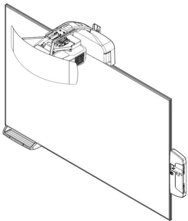
Technical line drawing of a mechanical assembly with a curved component mounted on a flat panel (no text or symbols)Epson All-in-One Collaborative Whiteboard AN2 87" and 100"
AN2 Series
DISCLAIMER
Milestone AV Technologies and its affiliated corporations and subsidiaries (collectively "Milestone"), intend to make this manual accurate and complete. However, Milestone makes no claim that the information contained herein covers all details, conditions or variations, nor does it provide for every possible contingency in connection with the installation or use of this product. The information contained in this document is subject to change without notice or obligation of any kind. Milestone makes no representation of warranty, expressed or implied, regarding the information contained herein. Milestone assumes no responsibility for accuracy, completeness or sufficiency of the information contained in this document.

IMPORTANT SAFETY INSTRUCTIONS

WARNING: A WARNING alerts you to the possibility of serious injury or death if you do not follow the instructions.

CAUTION: A CAUTION alerts you to the possibility of damage or destruction of equipment if you do not follow the corresponding instructions.

WARNING: Failure to read, thoroughly understand, and follow all instructions can result in serious personal injury, damage to equipment, or voiding of factory warranty! It is the installer's responsibility to make sure all components are properly assembled and installed using the instructions provided.

WARNING: Failure to provide adequate structural strength for this component can result in serious personal injury or damage to equipment! It is the installer's responsibility to make sure the structure to which this component is attached can support five times the combined weight of all equipment. Reinforce the structure as required before installing the component. The wall to which the mount is being attached may have a minimum drywall thickness of 1/2" (12.7mm) for wood and steel stud walls, and NO drywall on concrete walls.

WARNING: Use this mounting system only for its intended use as described in these instructions. Do not use attachments not recommended by the manufacturer.

WARNING: Never operate this mounting system if it is damaged. Return the mounting system to a service center for examination and repair.

WARNING: Do not use this product outdoors.
IMPORTANT ! : The AN2 Series includes the AN2 87" and 100" mounts. These mounts are designed to be used ONLY with the following Epson projector models:
• BrightLink Pro 1430Wi
• BrightLink Pro 1420Wi
- BrightLink 595Wi
- BrightLink 585Wi
IMPORTANT ! : The AN2 Series systems are designed to be mounted to:
- a bare 8" concrete or 8"x8"x16" concrete block wall;
- a 2" x 4" wood studs (16" on center minimum to 24" on center maximum) wall with a minimum drywall thickness of 1/2" (12.7mm);
- a 2" x 4"-25ga minimum steel studs (16" on center minimum to 24" on center maximum) wall with a minimum drywall thickness of 1/2" (12.7mm).
--SAVE THESE INSTRUCTIONS--
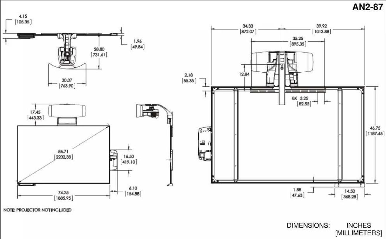
DIMENSIONS
text_image
4.15 [105.35] 30.80 [782,41] 30.07 [763,90] 1.96 [49,84]
text_image
17.45 [443.33] 99.96 [2538.93] 16.50 [419.10] 85.34 [2167.64] 6.10 [154.88]NOTE: PROJECTOR NOT INCLUDED

text_image
39.96 [1014.94] 45.54 [1156.76] 35.25 [895.35] 12.84 2.18 [55.35] 8X 3.25 [82,55] 53.75 [1365.25] 1.88 [47.63] 14.50 [368.28]DIMENSIONS: INCHES [MILLIMETERS]
AN2-100
LEGEND
 | Tighten Fastener |  | Pencil Mark |
| Apretar elemento de fijación | Marcar con lápiz | ||
| Befestigungsteil festziehen | Stiftmarkierung | ||
| Apertar fixador | Marcar com lápis | ||
| Serrare il fissaggio | Segno a matita | ||
| Bevestiging vastdraaien | Potloodmerkteken | ||
| Serrez les fixations | Marquage au crayon | ||
 | Loosen Fastener |  | Drill Hole |
| Aflojar elemento de fijación | Perforar | ||
| Befestigungsteil lösen | Bohrloch | ||
| Desapertar fixador | Fazer furo | ||
| Allentare il fissaggio | Praticare un foro | ||
| Bevestiging losdraaien | Gat boren | ||
| Desserrez les fixations | Percez un trou | ||
 | Phillips Screwdriver |  | Adjust |
| Destornillador Phillips | Ajustar | ||
| Kreuzschlitzschraubendreher | Einstellen | ||
| Chave de fendas Phillips | Ajustar | ||
| Cacciavite a stella | Regolare | ||
| Kruiskopschroevendraaier | Afstellen | ||
| Tournevis à pointe cruciforme | Ajuster | ||
 | Open-Ended Wrench |  | Remove |
| Llave de boca | Quitar | ||
| Gabelschlüssel | Entfernen | ||
| Chave de bocas | Remover | ||
| Chiave a punte aperte | Rimuovere | ||
| Steeksleutel | Verwijderen | ||
| Clé à fourche | Retirez | ||
 | By Hand |  | Optional |
| A mano | Opcional | ||
| Von Hand | Optional | ||
| Com a mão | Opcional | ||
| A mano | Opzionale | ||
| Met de hand | Optie | ||
| À la main | En option | ||
 | Hex-Head Wrench |  | Security Wrench |
| Llave de cabeza hexagonal | Llave de seguridad | ||
| Sechskantschlüssel | Sicherheitsschlüssel | ||
| Chave de cabeça sextavada | Chave de segurança | ||
| Chiave esagonale | Chiave di sicurezza | ||
| Zeskantsleutel | Veiligheidssleutel | ||
| Clé à tête hexagonale | Clé de sécurité |
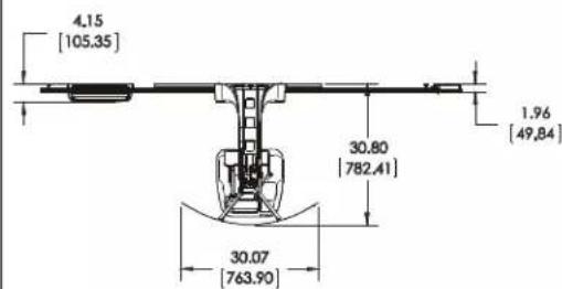
TOOLS REQUIRED FOR INSTALLATION
text_image
75/31 1/8" (wood) 1/2" (drywall) 8mm (concrete) 6mm (concrete - AF6 toggler) 3/8" 7/16" #1, #2 3/8" 7/16" 1 2 3 4 5PARTS
text_image
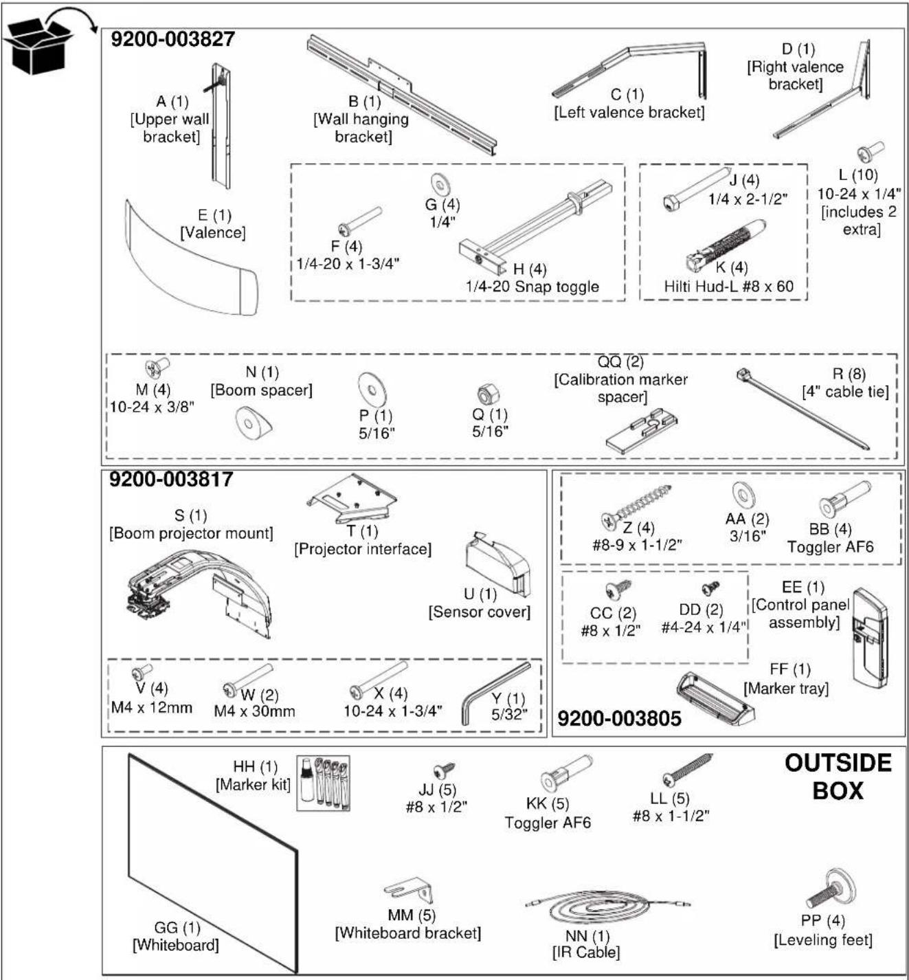
9200-003827 A (1) [Upper wall bracket] B (1) [Wall hanging bracket] C (1) [Left valence bracket] D (1) [Right valence bracket] E (1) [Valence] F (4) 1/4-20 x 1-3/4" G (4) 1/4" H (4) 1/4-20 Snap toggle J (4) 1/4 x 2-1/2" L (10) 10-24 x 1/4" [includes 2 extra] Hilti Hud-L #8 x 60 M (4) 10-24 x 3/8" N (1) [Boom spacer] P (1) 5/16" QQ (2) [Calibration marker spacer] R (8) [4" cable tie] 9200-003817 S (1) [Boom projector mount] T (1) [Projector interface] U (1) [Sensor cover] Z (4) #8-9 x 1-1/2" AA (2) 3/16" BB (4) Toggler AF6 CC (2) #8 x 1/2" DD (2) #4-24 x 1/4" EE (1) [Control panel assembly] FF (1) [Marker tray] V (4) M4 x 12mm W (2) M4 x 30mm X (4) 10-24 x 1-3/4" Y (1) 5/32" 9200-003805 HH (1) [Marker kit] JJ (5) #8 x 1/2" KK (5) Toggler AF6 LL (5) #8 x 1-1/2" GG (1) [Whiteboard] MM (5) [Whiteboard bracket] NN (1) [IR Cable] PP (4) [Leveling feet] OUTSIDE BOXINSTALLATION
Determining Location

text_image
10 5/8" [270mm] 2 3/4" [70mm] CENTER OF SCREEN 2 1 HEIGHT FROM FLOOR STUDS FLOOR 3 ③ ④ ⑤Figure 1
- Determine desired height of whiteboard (measured from floor). (See Figure 1)
- Determine desired center of whiteboard. (See Figure 1)
- Measure 10-5/8 inches (270mm) up from desired height (top) of whiteboard and 2-3/4 inches (69mm) to the right of center of whiteboard and mark location. (See Figure 1)
NOTE: This pilot hole may be placed in drywall only, if necessary.
-
Determine location of studs behind drywall.
-
Drill one pilot hole (see Table 1 for size) at location marked in Step 3 (See Figure 1) and follow fastener information (appropriate for wall type) located in Table 1.
IMPORTANT ! : See Fastener Installation Methods at end of Installation Instructions for details on installing product into various wall types.
Table 1: Fastener Information
| WALL TYPE PILOT HOLE | FASTENERS (see PARTS drawing) | |
| Drywall only- (boom attach only) / Steel studs | 1/2" 1/4-20 | Toggler anchor kit (F, G, H)- 1/4-20 x 1-3/4" Phillips screw (F)- 1/4" washer (G)- 1/4-20 Snap toggler (H) |
| Wood stud | 1/8" 1/4 x 2 | 1/2" hex head lag (J)1/4" washer (G) - OPTIONAL |
| Concrete | 8mm x 80mm | 1/4 x 2-1/2" hex head lag (J)Hilti Hud-L #8x60 anchor (K) |
| (Only for installing whiteboard bracket into concrete)6mm x 45mm | #8-9x1-1/2" Phillips screw (Z) Toggler AF6 (BB) or (KK) | |
Installing Wall Bracket
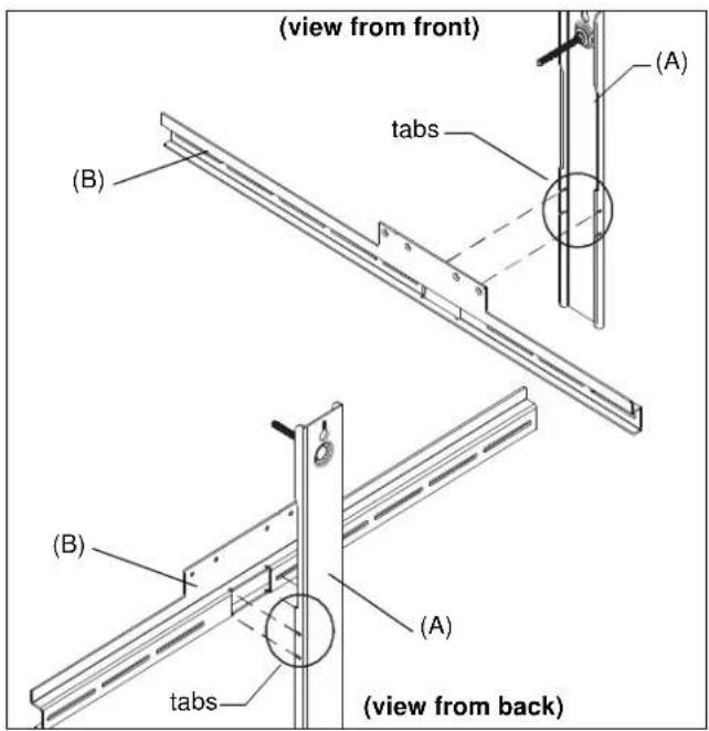
- Slide the tabs on the upper wall bracket (A) into the slots on wall hanging bracket (B). (See Figure 2)
text_image
(view from front) (B) tabs (A) (B) (B) tabs (A) (view from back)Figure 2
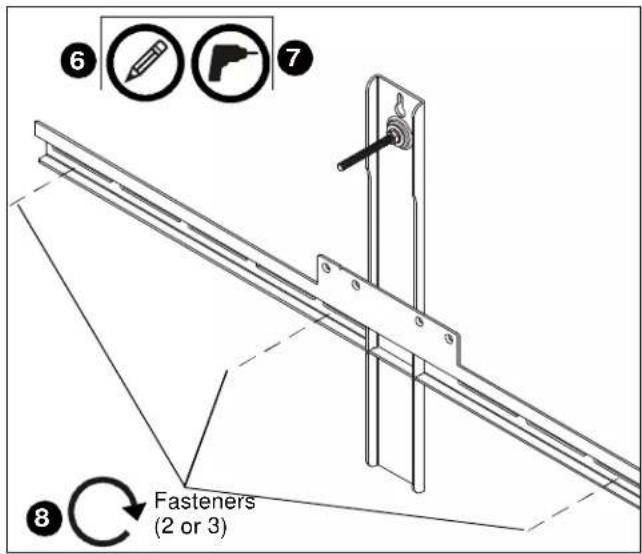
- Install one fastener (See Table 1) into previously drilled hole, leaving 1/2" of fastener extending from wall. (See Figure 3)
- Hang wall bracket assembly onto fastener. (See Figure 3)
NOTE: Notch in wall bracket assembly indicates center of whiteboard.

text_image
② ④ Fastener ③ Notch indicates center of screenFigure 3
-
Level wall bracket assembly.
-
Tighten fastener against wall bracket. (See Figure 3)
- Determine location of studs behind drywall, and mark a minimum of two locations for wall bracket attachment over studs. (See Figure 4)
NOTE: For wood or steel stud walls, mark at least two locations for attachment a minimum of 16" apart and a maximum of 24" apart, AND within slots on wall bracket assembly.
NOTE: For concrete walls, mark at least two locations for attachment a minimum of 16" apart, AND within slots on wall bracket assembly.
- Drill one pilot hole (see Table 1 for size) at each location marked in Step 5 (See Figure 4) and follow fastener information (appropriate for wall type) located in Table 1.
text_image
6 7 8 Fasteners (2 or 3)Figure 4
NOTE: Proceed to Fastener Installation Methods section at end of Installation Instructions.
- Fasten wall bracket assembly to wall using fasteners appropriate to wall type (See Table 1). (See Figure 4)
Installing Boom Projector Mount
IMPORTANT ! : The boom projector mount ships ready to install for the AN2 87" model.
• AN2-87: Proceed to Step 6.
• AN2-100: Proceed to Steps 1 - 5.
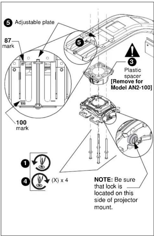
- (AN2-100 Only) Support the projector mount from underneath the boom arm while removing the four screws and washers from bottom of projector mount. (See Figure 5)
text_image
5 Adjustable plate 87 mark 100 mark 100 mark 3 Plastic spacer [Remove for Model AN2-100] NOTE: Be sure that lock is located on this side of projector mount. 1 4 (X) x 4Figure 5
- (AN2-100 Only) Lower projector mount and hardware from underneath boom arm.
- (AN2-100 Only) Remove and discard plastic spacer. (See Figure 5)
IMPORTANT ! : Make sure that lock on projector mount is located on correct side of boom arm. (See Figure 5)
IMPORTANT ! : Make sure that plastic glides on top of boom arm haven't shifted. Be sure to fasten Phillips machine screws (W) through the plastic glides.
-
(AN2-100 Only) Replace long fasteners with four 10-24 x 1-3/4" Phillips machine screws (X), and refasten projector mount to boom arm. (See Figure 5)
-
(AN2-100 Only) Turn adjustment bolt to move projector mount towards end of boom arm, until front of adjustable plate lines up with "100" marking on boom arm. (See Figure 5)
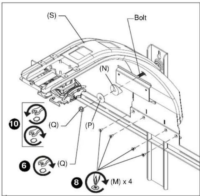
- Hang boom projector mount (S) over bolt on wall bracket assembly and loosely fasten (hand tighten) using boom spacer (N), 5/16" washer (P) and 5/16" nut (Q). (See Figure 6)
- Align four fastener holes along bottom of boom projector mount behind four holes in wall bracket. (See Figure 6)
- Install and tighten four 10-24 x 3/8" Phillips flat head screws (M) through wall bracket assembly into boom projector arm (S). (See Figure 6)
text_image
(S) Bolt (N) (Q) (P) 10 6 (Q) 8 (M) x 4Figure 6
- Place level lengthwise on top of boom projector arm (S).
- Level boom projector arm (S) by loosening or tightening the 5/16" nut (Q) on the bolt from the wall bracket assembly. (See Figure 6)
Installing Whiteboard and Sensor
IMPORTANT ! : Use at least two people when lifting and installing whiteboard. Handle the frame and back of whiteboard, and avoid touching the front of whiteboard as much as possible.
- Lay box flat and open.
- Stand whiteboard up and add leveling feet (PP) to each corner on the back of whiteboard. Do not over tighten. (See Figure 7)
- Hang whiteboard (GG) onto wall bracket assembly using pre-installed bracket on back of whiteboard assembly. (See Figure 7)

text_image
(View shown from behind wall to which wall bracket assembly is attached) (S) Pre-installed bracket (GG) 3 Wall bracket assembly 2 (PP) x 4 3 5Figure 7
- Center whiteboard assembly on wall bracket.
NOTE: Notch in wall bracket assembly indicates center of whiteboard. - Level the whiteboard against the wall by placing a level against the front of it, and adjusting the leveling feet. (See Figure 7)
- Continue to adjust until whiteboard is leveled with the wall.
- Remove and keep one fastener from bottom of sensor.
NOTE: The sensor is included with the Epson projector, not the AN2BA Series mount.

natural_image
Isometric view of a rectangular electronic device with a labeled arrow pointing to a slot (no text or symbols beyond the number 8)Figure 8
- Remove and keep sensor cover. (See Figure 8)
- Attach sensor to boom arm bracket using two M4 x 30mm Phillips cap head screws (W). (See Figure 9)
NOTE: Insert the two Phillips screws into sensor. The magnets on the sensor will hold the sensor in place on the bracket while fastening the screws.

text_image
(W) x 2Figure 9
Installing Projector
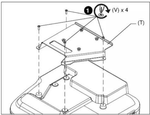
- Attach projector interface (T) to projector using four M4 x 12mm Phillips cap head screws (V). (See Figure 10)
text_image
(V) x 4 (T)Figure 10
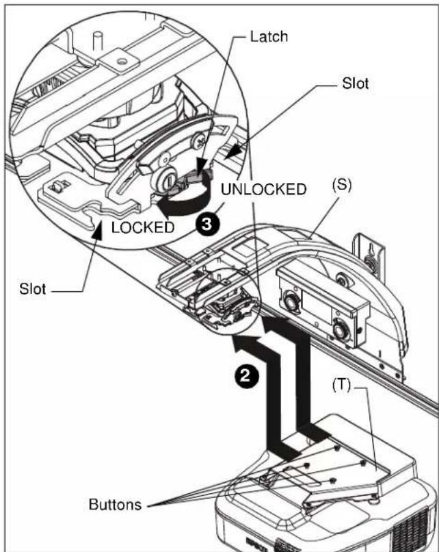
NOTE: Make sure projector mount is in UNLOCKED position and remove key from projector mount.(See Figure 11)
- Lift projector with attached interface (T) and slide buttons on interface into slots on boom projector mount (S). (See Figure 11)
- Slide latch to LOCKED position to lock projector in place. (See Figure 11)
- Add and route cables following instructions included with the projector.
NOTE: Do NOT place extra cable length behind the sensor bracket.
text_image
Latch Slot UNLOCKED (S) LOCKED 3 Slot 2 (T) ButtonsFigure 11
- Place a level on top of the boom arm mount and level the mount after the projector is installed. (See Figure 12)
5A. Tighten nut to increase boom arm angle.
5B. Loosen nut to decrease boom arm angle.
- Place a level on top of interface (T) and level. (See Figure 12)

CAUTION: While leveling mount:
• Ensure nut is fully engaged onto bolt, and AT LEAST ONE thread appears through nut.
• DO NOT over tighten nut! Over tightening WILL damage wall behind mount.

text_image
5A 5B 5A 5BFigure 12
Align Projector Image
Using remote control included with projector:
- Select MENU
- Select SETTINGS
- Select PATTERN
- Select TEST PATTERN
- Use the test pattern projected on the whiteboard to roughly align image to whiteboard, and make the necessary projector adjustments following instructions included with Epson projector and using the following adjustment instructions for the mount.
IMPORTANT ! : The projected image should NEVER project onto the whiteboard frame. An image overlapping onto the whiteboard frame may prevent the projector touch sensor from working properly.
Projector Adjustments
Roll Adjustment (Horizontal Tilt)
Adjust projector so that the left and right vertical lines of the test pattern are parallel with each other and each side of whiteboard.
- Loosen ROLL adjustment locking screw using a #2 Phillips screwdriver. (See Figure 13)
- Turn ROLL micro-adjustment screw right or left using a #2 Phillips screwdriver until image is properly aligned on target.
- Tighten ROLL adjustment locking screw using a #2 Phillips screwdriver.

text_image
Diagram illustrating engine compartmental changes with numbered annotations and directional arrows indicating adjustment or reassembly steps.Figure 13
Yaw Adjustment (Rotation)
Adjust projector so that the top and bottom horizontal lines of the test pattern are parallel with each other and with top and bottom of whiteboard.
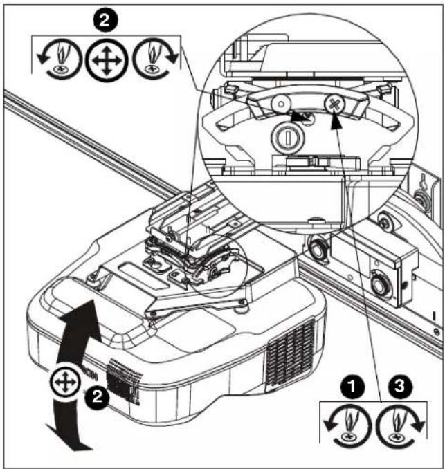
- Loosen yaw adjustment locking screw using a #2 Phillips screwdriver. (See Figure 14)
- Turn yaw micro-adjustment screw right or left using a #2 Phillips screwdriver until image is properly aligned on target.
- Tighten yaw adjustment locking screw using a #2 Phillips screwdriver. (See Figure 14)

text_image
Technical diagram showing engine component assembly with numbered parts and directional arrows indicating rotation or adjustment.Figure 14
Pitch Adjustment (Vertical Elevation)
Adjust projector so that the top and bottom horizontal lines of the test pattern are parallel with each other and with top and bottom of whiteboard.
- Loosen pitch adjustment locking screw using a #2 Phillips screwdriver. (See Figure 15)
- Turn pitch micro-adjustment screw right or left using a #2 Phillips screwdriver until image is properly aligned on target.
- Tighten pitch adjustment locking screw using a #2 Phillips screwdriver.
text_image
Technical diagram of a vehicle dashboard with labeled parts and directional arrows indicating motion or control actions.Figure 15
Micro Adjustment
IMPORTANT ! : The projected image should NEVER project onto the whiteboard frame. An image overlapping onto the whiteboard frame may prevent the projector touch sensor from working properly.
- If required, turn the micro adjust fastener clockwise to extend projector further from wall. (See Figure 16)
- If required, turn the micro adjust fastener counterclockwise to retract projector closer to wall.

text_image
1 Extend 2 RetractFigure 16
Installing Control Pad
- Open lower cover on control pad (included with projector). (See Figure 17)
- Insert control pad into control housing (EE) by sliding it up under tabs inside housing. (See Figure 17)
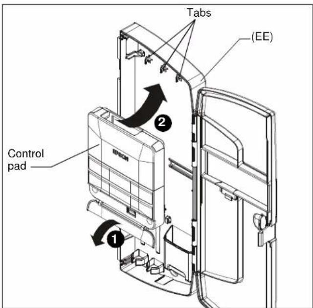
text_image
Tabs (EE) Control pad 1 2Figure 17
- Align holes in control pad with bosses in control housing and push control pad into place. (See Figure 18)
- Secure control pad into place using two #4-24 x 1/4" Phillips pan head screws (DD). Do NOT over tighten. (See Figure 18)
- Close lower cover of control pad. (See Figure 18)
- Attach all cables, including IR cable (NN), to control pad following instructions included with projector/control pad.
- Use cable ties (R), as necessary, to secure the cables within control panel. (See Figure 18)

text_image
Bosses (DD) x 2 Cable tie anchors Tab USB portFigure 18
8. OPTIONAL: The tab in the control panel assembly door may be removed to allow attachment to the USB port. (See Figure 18)
Installing Control Housing
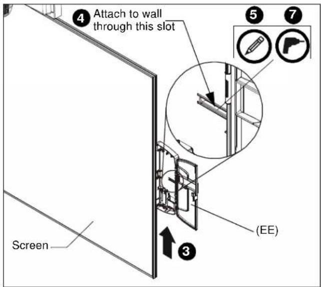
- Open door on control panel assembly (EE).
- Insert edges of control panel assembly (EE) into groove in whiteboard frame, with tab placed behind whiteboard. (See Figure 19)
- Slide control panel assembly up along side of whiteboard to the desired height. (See Figure 19)
- Determine attachment location on wall. (See Figure 19)
- Mark attachment hole through slot in control panel assembly (EE). (See Figure 19)
- Slide control panel assembly up or down, away from marked hole.
- Drill one pilot hole (see Table 1 for size) at location marked in Step 5 (See Figure 19) and follow fastener information (appropriate for wall type) located in Table 1.
- Proceed to Fastener Installation Methods section at end of Installation Instructions.
text_image
4 Attach to wall through this slot Screen ③ (EE) ⑤ ⑦Figure 19
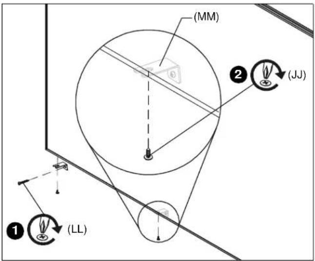
Adding Whiteboard Brackets to Whiteboard
NOTE: Use 3 whiteboard brackets (minimum of 2 brackets) along bottom of whiteboard, and locate brackets as close to outer corners as possible. Remaining brackets may be used along sides of whiteboard, as desired.
- Install whiteboard brackets (MM) using:
• Wood/steel studs/drywall: one #8 x 1-1/2" screw (LL) into back of each whiteboard bracket.
- Concrete wall: one #8 x 1-1/2" screw (LL) into back of each whiteboard bracket, and into installed AF6 toggler (KK).
- Fasten to whiteboard frame using one #8 x 1/2" self-drilling screw (JJ) per whiteboard bracket (MM).
text_image
(MM) ② (JJ) ① (LL)Figure 20
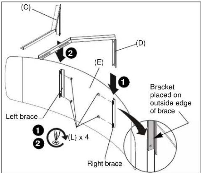
Attaching Valence
- Align right valence bracket (D) along outside of right brace on back of valence (E), and fasten with two 10-24 x 1/4" Phillips pan head machine screws (L). (See Figure 21)
- Align left valence bracket (C) along outside of left brace on back of valence (E), and fasten with two 10-24 x 1/4" Phillips pan head machine screws (L). (See Figure 21)
- Slide the valence (E) with attached brackets into the boom projector mount (S), sliding brackets under tabs in boom and adjust distance as required. (See Figure 22)
- Fasten through bracket slots into boom mount using four 10-24 x 1/4" Phillips pan head machine screws (L). (See Figure 22)
text_image
(C) 2 (E) 1 Left brace ① ② (L) x 4 Right brace (D) Bracket placed on outside edge of braceFigure 21

text_image
(E) Tabs (L) x 4 ④ ③Figure 22
- Readjust projector following instructions in the Align Projector Image section.
Calibrating Finger Touch Unit (FTU)
- Snap calibration marker spacers (QQ) into bottom of calibration markers included with Epson projector. (See Figure 23)
NOTE: Ensure that magnet on calibration marker spacer (QQ) lines up with target on calibration marker. (See Figure 23)

text_image
Target Calibration marker (QQ) x 2 MagnetFigure 23
- Calibrate the finger touch unit (FTU) following instructions included with the Epson projector.
Attaching Sensor Cover and Outer Cover
- Reattach the sensor cover, using the fastener previously removed. (See Figure 2)

natural_image
Technical line drawing of a car interior showing structural components and a numbered component (no text or symbols)Figure 24
-
Hold sensor outer cover (U) under boom projector mount and begin sliding downward toward top of whiteboard. (See Figure 25)
-
Continue sliding cover downward until tabs at bottom of cover slip into slot on top of whiteboard. (See Figure 25)
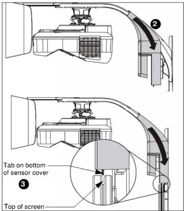
text_image
Tab on bottom of sensor cover Top of screenFigure 25
Attaching Marker Tray
- Attach marker tray (FF) at any point along bottom of whiteboard using two #8 x 1/2" self-drilling screws (CC). (See Figure 26)
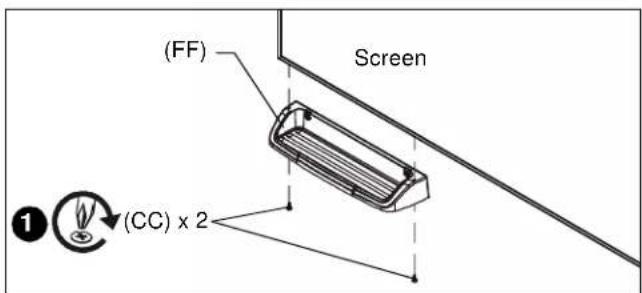
text_image
(FF) Screen (CC) x 2Figure 26
FASTENER INSTALLATION METHODS
NOTE: Refer to Table 1 for appropriate hardware and pilot hole sizes for various wall types.
Steel Stud / Drywall
- Hold metal channel on anchor (H) flat alongside plastic straps and slide channel through hole. (See Figure 27)
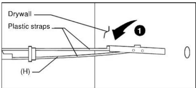
text_image
Drywall Plastic straps (H) 1Figure 27
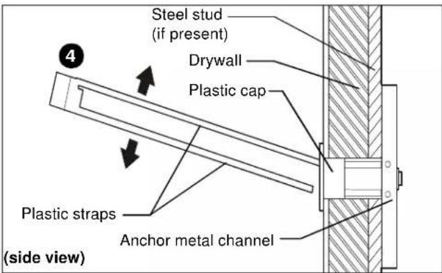
- Holding plastic straps on anchor (H), pull anchor away from wall until channel rests flush behind wall making sure anchor channel is positioned vertically on drywall, or steel stud (if present). (See Figure 28)
- Slide plastic cap on anchor (H) towards wall until flange of cap is flush with wall. (See Figure 28)
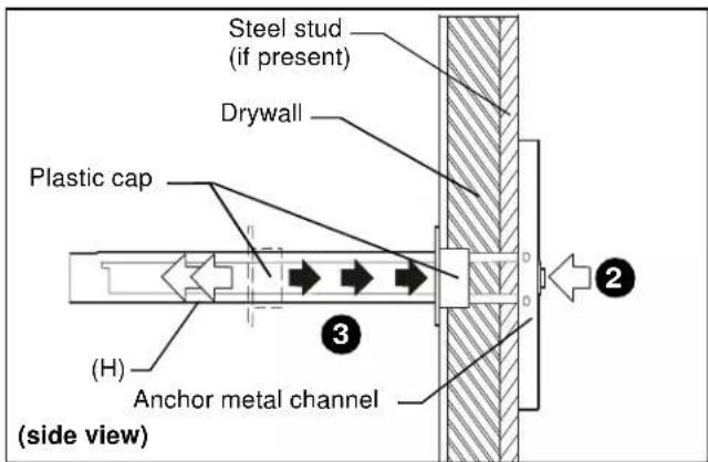
text_image
Steel stud (if present) Drywall Plastic cap (H) Anchor metal channel (side view)Figure 28
- Snap off plastic straps on anchor at wall by pushing side to side, snapping off straps level with flange of plastic cap. (See Figure 29)
text_image
Steel stud (if present) Drywall Plastic cap Plastic straps Anchor metal channel (side view)Figure 29
-
Line up anchor with attachment point.
-
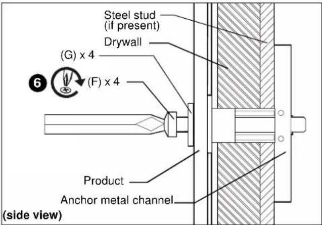
Insert 1/4-20 x 1-3/4" Phillips pan head screw (F) through 1/4" washer (G), corresponding mounting hole in product and into anchor (H), and tighten until flush against product. DO NOT over tighten! (See Figure 30)
text_image
Steel stud (if present) Drywall (G) x 4 (F) x 4 Product Anchor metal channel (side view)Figure 30
Wood Stud
NOTE: Refer to Table 1 for appropriate hardware and pilot hole sizes for various wall types.
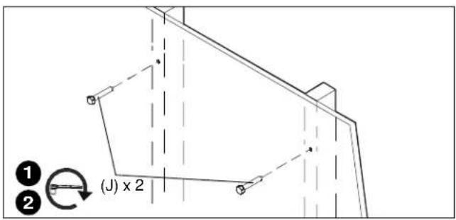
- Use one 1/4 x 2-1/2" lag bolt (J) through product and into pilot hole. (See Figure 31)
- Repeat for remaining pilot hole.
text_image
(J) x 2Figure 31
Concrete
NOTE: Refer to Table 1 for appropriate hardware and pilot hole sizes for various wall types.
- Install an anchor (K) into each pilot hole using a hammer, making sure that the anchor is flush with the wall.
- Use one 1/4 x 2-1/2" lag bolt (J) through product into each anchor in wall.

text_image
1 (K) 2 (J)Figure 32
milestone
LIMITED WARRANTY
AN2-100 Integrated Interactive Touch System AN2-87 Integrated Interactive Touch System
Milestone warrants to its customers that the solution and all solution options will (i) conform to the design specifications, (ii) be free from defects in design, material and workmanship for three (3) years after shipment to any customer of Milestone or a Milestone Partner, (iii) be free of all liens and claims against title, and (iv) not infringe the patent, copyright, trade secret or other intellectual property rights of any person or entity within the United States.
Milestone shall provide a three (3) year manufacturer's warranty, with the exception of reasonable wear and tear, for all solution units sold to the original end user (whether through Milestone Partners or otherwise). This limited warranty only extends to the original end user of the solution and not to any subsequent owner.
TO THE MAXIMUM EXTENT PERMITTED BY APPLICABLE LAW, MILESTONE DISCLAIMS ANY OTHER WARRANTIES, EXPRESS OR IMPLIED, INCLUDING WARRANTIES OF FITNESS FOR A PARTICULAR PURPOSE AND WARRANTIES OF MERCHANTABILITY. SOME STATES DO NOT ALLOW DISCLAIMERS OF IMPLIED WARRANTIES, SO THESE LIMITATIONS MAY NOT APPLY TO YOU. TO THE MAXIMUM EXTENT PERMITTED BY APPLICABLE LAW, MILESTONE DISCLAIMS ANY RESPONSIBILITY FOR INCIDENTAL OR CONSEQUENTIAL DAMAGES. SOME STATES DO NOT ALLOW THE EXCLUSION OR LIMITATION OF INCIDENTAL OR CONSEQUENTIAL DAMAGES, SO THE ABOVE LIMITATION OR EXCLUSION MAY NOT APPLY TO YOU.
Any solution units subject to the warranty shall be repaired, replaced or taken back for credit or refund (election to be made by Milestone in consultation with its Milestone Partners)
MILESTONE AV TECHNOLOGIES
USA P 800.582.6480 / +1.952.225.6000 • F 877.894.6918 / +1.952.894.6918 n chief@chiefmfg.com
Canada P 877.345.4329 n F 888.377.5314 n canadainfo@milestone.com EMEAP +31 495 580 840 n F +31 495 580 845 n emea.sales@milestone.com Asia Pacific P +852 2145
4099 n F +852 2145 4477 n asia.chief@milestone.com
In British Columbia, Milestone AV Technologies ULC carries on business as MAVT Milestone AV Technologies ULC.
8800-002671 Rev02 06/15
Milestone AV Technologies
3100 North Detroit Street, Warsaw, IN 46582
P: 574.267.8101 or 800.622.3737
F: 574.267.7804 or 877.325.4832
E: info@da-lite.com
www.milestone.com
© 2015 Milestone AV Technologies LLC