XF511H100MF - Sewing machine Union Special - Free user manual and instructions
Find the device manual for free XF511H100MF Union Special in PDF.

User questions about XF511H100MF Union Special
0 question about this device. Answer the ones you know or ask your own.
Ask a new question about this device
Download the instructions for your Sewing machine in PDF format for free! Find your manual XF511H100MF - Union Special and take your electronic device back in hand. On this page are published all the documents necessary for the use of your device. XF511H100MF by Union Special.
USER MANUAL XF511H100MF Union Special
Maximum performance XF500 Series flatbed machines
FORWARD
This technical manual has been prepared to guide you in the maintenance of your new UNION SPECIAL MACHINE. Careful attention to the instructions for operating and adjusting these machines will enable you to maintain the superior performance and reliability designed and built into every UNION SPECIAL machine.
The Adjusting Instruction portion of this manual explains in detail the proper setting for each of the components related to forming the stitch and completing the functions of the machine. Figures are used to illustrate the adjustments using reference letters to point out specific items discussed.
Implementation of Preventive Maintenance Schedule can bring about significant improvements in operator productivity by avoiding costly equipment breakdowns. Whenever it becomes necessary to make repairs or replace parts on your machine, be sure to insist on genuine UNION SPECIAL Repair Parts. These parts are designed specifically for your machine and manufactured with utmost precision to assure long lasting service.
This Catalog has been made on the basis of available information. Changes in design and/or improvements may incorporate a slight modification of configuration in illustrations or part numbers.
CATALOG NO. 142M
SECOND EDITION
Copyright 1989
PRINTED IN USA
DECEMBER, 1989
INFORMATION SUBJECT TO CHANGE WITHOUT NOTICE
Each UNION SPECIAL machine is identified by a Style number, which on this machine Class, is stamped into the Style plate affixed to the right front of machine. Serial number is stamped into bed casting at the right rear base of machine.
NOTE: Instructions stating direction or location, such as right, left, front, or rear of machine, are given relative to the operator's position at the machine, unless otherwise noted. The handwheel rotates counterclockwise in operating direction, as viewed from the right end of the machine.
STYLES OF MACHINES
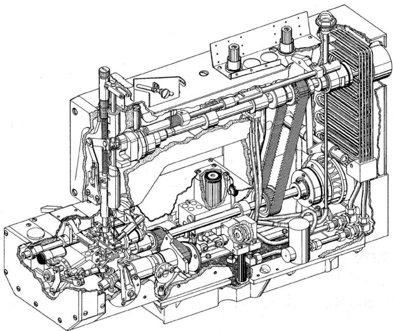
High speed, maximum performance, long arm flatbed, double locked stitch, plain feed machine. Totally enclosed feed and looper drive mechanism, fully automatic forced feed lubricating system with easily replaceable oil filter, independently driven rear needle guard, adjustable feed lift, quick adjustable looper avoid and built-in needle cooler.
XF511B100MF Single needle, MEDIUM capacity, wrench adjustable stitch change, thumbscrew adjustable needle frame eyelet, low inertia presser foot, permitting light presser foot pressure for positive feeding and chaining at high speeds; for long seams on light to medium weight fabrics such as trousers, skirts, coats, jackets, etc. Standard recommended needle Type 128 GBS, Size 90/036. Stitch range 7-10 S.P.I. Maximum recommended speed 8000 R.P.M., depending on operation.
XF511E101MF Single needle, MEDIUM capacity, quick stitch change mechanism, thumbscrew adjustable needle frame eyelet, low inertia presser foot permitting light presser foot pressure for positive feeding and chaining at high speeds. Equipped with a Close-Coupled Roller Puller, for long flat seams on medium weight fabrics such as trousers, coats, and perma-press materials. Standard recommended needle Type 128 GBS, Size 90/036. Stitch range 7-10 S.P.I. Maximum recommended speed 7500 R.P.M., depending on operation.
XF511E118MF Same as Style XF511E101MF except-equipped with Belt Puller.
XF511E152MF Same as Style XF511E118MF except-equipped with Power "AIR-KLIPP"® Chain Cutter.
XF511H100MF Same as Style XF511B100MF except-equipped with built-in oil cooler and quick stitch change mechanism. Maximum recommended speed 9000 R.P.M., depending on operation. Stitch range 7-10 S.P.I.
XF511H100MG Same as Style XF511H100MF except used for side and inseaming on men's work and dress pants made from medium weight material. Stitch range 10-14 S.P.I.
XF511H100MAW Same as Style XF511H100MF except-equipped with narrow feeding presser foot parts for a 3/16 inch (4.8mm) margin. Stitch range 7-10 S.P.I. Maximum recommended speed 8000 R.P.M., depending on operation.
XF511H112MF Same as Style XF511H100MF except-equipped with Power "AIR-KLIPP" Chain Cutter.
XF511H112MG Same as Style XF511H100MG except-equipped with Power "AIR-KLIPP" Chain Cutter.
STYLES OF MACHINES (Continued)
| XF511H151MF | Same as Style XF511H100MF except-equipped with Power "AIR-KLIPP" Chain Cutter and pneumatic stitch shortening device. |
| XF512E100HB | Two needle, HIGH capacity, for seaming trousers and similar garments made of medium heavy to heavy weight material. Right needle in front. Standard recommended needle Type 128 GBS, Size 100/040. Available in 7 S.P.I. ONLY. Standard gauge No. 1 ONLY. The seam produced has two rows of stitching with the strength of 14 S.P.I., yet the fabric is moved forward at a rate of 7 S.P.I. Maximum recommended speed 6500 R.P.M., depending on operation. |
| XF512E100MP | Two needle, MEDIUM capacity, quick stitch change mechanism, for piecing sleeves, joining shoulders and setting sleeves on ordinary quality shirts made with light to medium weight materials. Includes double lap seam folder 1/16 inch (1.6mm) capacity. Standard recommended needle Type 108 GHS, Size 70/027. Stitch range 9-14 S.P.I. Standard gauge Nos. 12 and 16. Maximum recommended speed 6500 R.P.M., depending on operation. |
| XF513E100HJ | Three needle, HIGH capacity, quick stitch change mechanism, for seaming wind breakers, mackinaws, lumber jacks and for similar operations on medium heavy to heavy weight material. Equipped with tractor type presser foot, Includes double lap seam folder 3/32 inch (2.4mm) capacity. Standard recommended needle Type 128 GAS, Size 125/049. Stitch range 7-10 S.P.I. Standard gauge Nos. 8 and 9. Maximum recommended speed 6500 R.P.M., depending on operation. |
| XF513E100HR | Three needle, HIGH capacity, quick stitch change mechanism, for seaming sanforized denim and similar operations on medium to heavy weight materials. Includes double lap seam folder 1/8 inch (3.2mm) capacity. Standard recommended needle Type 128 GAS, 125/049. Stitch range 7-10 S.P.I. Standard gauge No. 9 ONLY. Maximum recommended speed 6500 R.P.M., depending on operation. |
| XF513E101HR | Same as Style XF513E100HR except-equipped with a Close-Coupled Roller Puller. |
| XF513E112HR | Same as Style XF513E100HR except-equipped with Power "AIR-KLIPP" Chain Cutter. |
®"AIR-KLIPP" is a registered trademark of Union Special Corporation.
SAFETY RULES

CAUTION!
THIS SAFETY SYMBOL INDICATES YOUR PERSONAL SAFETY IS INVOLVED
TO PREVENT PERSONAL INJURY:
- All power sources to the machine MUST be TURNED OFF before threading, oiling, adjusting or replacing parts.
- Wear safety glasses.
- All shields and guards MUST be in position before operating machine.
- DO NOT tamper with safety shields, guards, etc., while machine is in operation.
LUBRICATION
IMPORTANT: Machine must be in a leveled position.
Oil has been drained from main reservoir before shipment. Use a straight mineral oil with a Saybolt viscosity of 90 to 125 seconds at 100 degrees Fahrenheit. This is equivalent to UNION SPECIAL Specification No. 175. Remove oil filler cap (A, Fig. 1) and fill to TOP line of oil level gauge (B). Replace oil filler cap.
CAUTION! On new machines, machines that have been out of service for an extended period of time OR machines that have been drained of oil and refilled... run machine slowly at 300 R.P.M. for approximately five minutes while paying strict attention to the oil flow indicator which should rise in the oil filler cap (A) and remain steady while machine is running. This must be noted to ensure that oil flow indicator is functioning and oil is circulating. Run machine and recheck oil level which MUST be maintained between the red lines of oil gauge.
To maintain maximum recommended speed and serviceability of these machines, refer to General Preventive Maintenance Schedule. Under no circumstances, should oil remain in the machine for more than one year. Two oil drain plugs are located in bottom of oil pan. ALWAYS replace oil filter when oil is changed. To replace filter remove four screws (C, Fig. 1), cover (D) and lift out filter, REMOVE (brass) BY-PASS VALVE FROM TOP OF OLD FILTER AND INSTALL IN NEW FILTER. Reassemble in reverse manner.
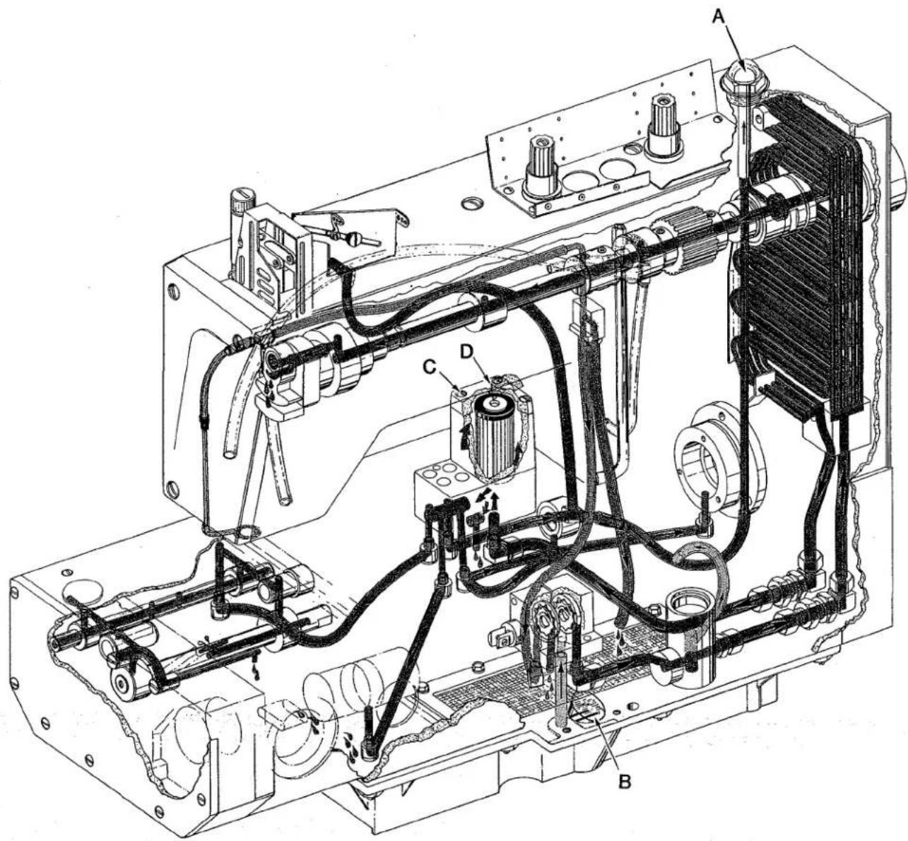
text_image
Technical schematic diagram of an electrical or mechanical device with labeled components A, B, C, and D
PRESSURE OIL

SIPHON RETURN

RETURN OIL

PRIORITY VALVE PRESSURE

INLET

FILTER BY-PASS
Fig. 1
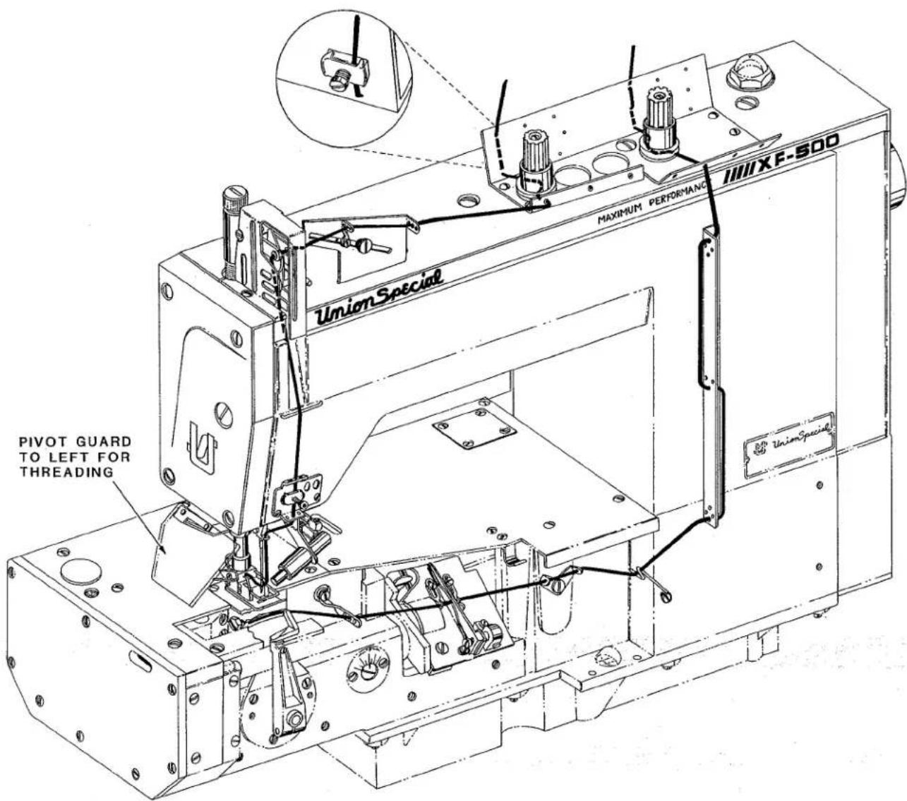
text_image
PIVOT GUARD TO LEFT FOR THREADING UNION SPECIAL MAXIMUM PERFORMANCE UNION SPECIAL UNION Special UNION Special UNION Special UNION Special UNION Special UNION Special UNION Special UNION Special UNION Special UNION Special UNION Special UNION Special UNION Special UNION Special UNION Special UNION Special UNION Special UNION Special UNION Special UNION Special UNION Special UNION Special UNION Special UNION Special UNION Special UNIONSpecialA205
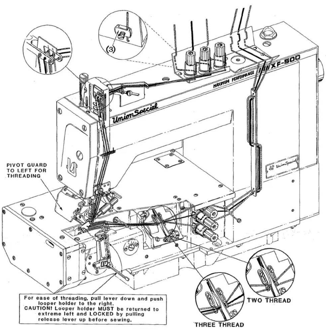
text_image
UNION Special MAXIMUM PERFORMANCE U18XF-500 PIVOT GUARD TO LEFT FOR THREADING For ease of threading, pull lever down and push looper holder to the right. CAUTION! Looper holder MUST be returned to extreme left and LOCKED by pulling release lever up before sewing. THREE THREAD TWO THREADA206
THREADING DIAGRAM
NEEDLES
Each needle has both a type and size number. Type number denotes the kind of shank, point, length, groove, finish, and other details. Size number, stamped on the needle shank in metric, denotes largest diameter of blade, measured midway between shank and eye. Collectively, type and size number represent the complete symbol, which is given on the label of all needles packaged and sold by UNION SPECIAL CORPORATION.
The type numbers of the needles recommended for each Style of machine covered by this catalog are given in the machine style description. Other needles are available, but the ones indicated are those recommended to produce the most satisfactory results. The type numbers of the recommended needles together with their descriptions, and the sizes available are listed below:
| NEEDLE TYPE | DESCRIPTION | SIZES AVAILABLE |
| 108 GHS | Round shank, ball point, double groove, struck groove, ball eye, spotted, chromium plated. | 70/027, 75/029, 80/032, 90/036, 125/049. |
| 128 GAS | Round shank, round point, short, double groove, struck groove, ball eye, spotted, chromium plated. | 80/032, 90/036, 100/040, 110/044, 125/049, 140/054, 150/060, 170/067. |
| 128 GBS | Round shank, round point, short, double groove, struck groove, ball eye, spotted, ball point, chromium plated. | 80/032, 90/036, 100/040, 110/044, 125/049, 140/054, 150/060. |
To have needle orders promptly and accurately filled, an empty package, a sample needle, or the type and size number should be forwarded. Use description on label. A complete order would read "1000 needles, Type 128 GBS, Size 90/036".
The following instructions explain in detail the proper setting for each of the components related to forming the stitch and completing the functions of the machine.
Adjustments are presented in sequence so that a logical progression is accomplished. Some adjustments performed out of sequence may have adverse effect on the function of other related parts.
NOTE: On earlier styles, machines equipped with a DURACOAT ALUMINUM needle bar; TORQUE needle bar connection screw, 10 to 12 in-lbs. (11.5 to 13.8 cm/kg).
On later styles, machines equipped with a DURACOAT MASKED ALUMINUM needle bar; TORQUE needle bar connection screw, 16 to 18 in-lbs. (18.4 to 20.7 cm/kg).
THREAD MACHINE AS ILLUSTRATED.
TIMING FEED TO NEEDLE
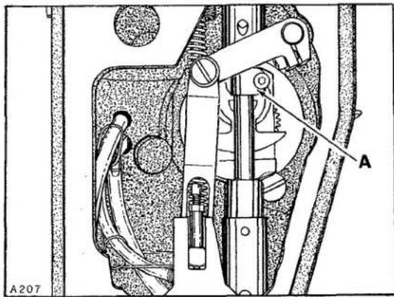
text_image
A A207Fig. 2
Adjustment would be required if machine is feeding while the needle or needles are in the work.
To adjust; remove top cover, head cover and all other plates, supports and covers as required to provide accessibility to the feed mechanism chamber. Turn handwheel in operating direction to position needle bar connection (A, Fig. 2) at TOP of stroke.
Loosen four screws (A, Fig. 3) in upper mainshaft sprocket (B) and hold handwheel so upper mainshaft and needle bar cannot move. While holding handwheel firmly, turn lower mainshaft to position feed crank counterweight (A, Fig. 4) with its FLATS perpendicular to the bottom of machine and facing away from the operator, as viewed in Figure 4. TORQUE screws (A, Fig. 3) to 36 in-lbs (41 cm/kg).

text_image
A A B A208Fig. 3
NOTE: Whenever "TIMING FEED TO NEEDLE" is corrected, always check "SYNCHRONIZING LOOPER AND NEEDLE MOTIONS."
SYNCHRONIZING LOOPER AND NEEDLE MOTIONS
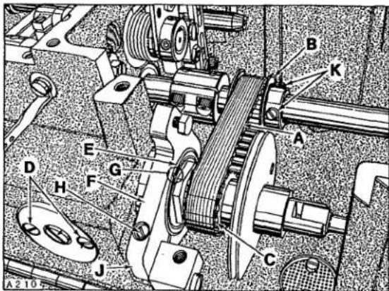
Looper drive belt (A, Fig. 5) has proper tension if, when turning handwheel in operating direction to position looper in the center of its (right to left) travel... there is no noticeable (right to left) play in the looper mechanism.

text_image
FLATS A A209Fig. 4
There should be approximately 1/8 inch (3.2mm) deflection in looper drive belt when pressing firmly with thumb, midway between sprockets (B and C). Adjustment can be made by loosening two screws (D) and turn looper module (E) clockwise (as viewed from handwheel end of machine) to tighten belt tension or counterclockwise to loosen belt tension.
It is easier to rotate looper module by turning cast-off plate mounting bracket (F). At this time, notch (G) on end of looper module should be facing in the upward position (between 9 and 3 o'clock). Loosen binder screw (H) and reposition cast-off plate mounting bracket (F) so its leading edge (J) is vertical to and parallel with bed casting. Retighten screw (H) assuring that the right side of mounting bracket is flush with right side of looper module. Retighten screws (D).
SYNCHRONIZING LOOPER AND NEEDLE MOTIONS (Continued)
To synchronize machine, remove needle bar eyelet guard, needle thread take-up cam wire, needle/s, presser foot, throat plate, looper/s, and feed dog. Turn handwheel to position needle bar at BOTTOM of stroke and looper holder at EXTREME right end of travel.
Using gauge No. 21227 R, mount gauge plate with throat plate attaching screws. Insert pin (included with gauge) into looper holder. Mount indicator block to machine head with one of the screws removed from needle bar eyelet guard. Insert shank of indicator gauge into indicator block tighten screw against shank, (See Sketch A for reference).
NOTE: For Style XF512's and XF513's use 21227 AD mounting plate.
Rotate handwheel in OPERATING direction until the pin in looper holder contacts gauge plate. Loosen screw (A, Fig. 6) in needle bar connection (B) and position needle bar (C) as required to set the pointer of indicator gauge at "0" and tighten screw (A) VERY LIGHTLY.
IMPORTANT: Refer to NOTE, page 9 for proper TORQUE of screw.
Rotate handwheel in REVERSE direction until pin in looper holder again makes contact with gauge plate and note the reading on the gauge. A variation of (1) graduation on the scale is permissible. If the reading is above "0", loosen screws (K, Fig. 5) while holding sprocket (B), turn handwheel clockwise. If the reading is below "0", hold sprocket, turn handwheel counterclockwise. Temporarily snug screws.
Rotate handwheel in OPERATING direction until pin in looper holder contacts gauge plate and note the reading on scale. If the reading is above "0", loosen screws (K) while holding sprocket (B), turn handwheel counterclockwise. If the reading is below "0", hold sprocket and turn handwheel clockwise. Temporarily snug screws.
text_image
Technical diagram of a mechanical assembly with labeled components A through J, showing gears and linkages.Fig. 5

natural_image
Technical line drawing of a sewing machine with no visible text or symbolsSKETCH A

text_image
A212 B C AFig. 6
SYNCHRONIZING LOOPER AND NEEDLE MOTIONS (Continued)

text_image
LOOPER BEHIND NEEDLE LOOPER IN FRONT OF NEEDLE GREATEST LEAST A 107 OPERATING DIRECTIONSKETCH B
Continue to check and adjust in both OPERATING and REVERSE directions until pointer of indicator gauge comes within (1) graduation on the scale when turning the handwheel in either direction and tighten screws (K) securely, assuring that drive belt is centered on sprockets.
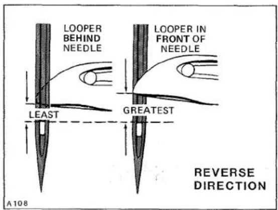
If a synchronizing gauge is not available... turn the handwheel in operating direction to position looper point even with the left side of RIGHT needle and check the distance from the eye of needle to the bottom of looper blade.
text_image
LOOPER BEHIND NEEDLE LEAST GREATEST LOOPER IN FRONT OF NEEDLE A108 REVERSE DIRECTIONSKETCH C
Turn handwheel in reverse direction to position looper even with the left side of RIGHT needle and check the distance from the eye of needle to the bottom of looper blade. If the distance was greater when handwheel was turned in operating direction, as viewed in Sketch B, loosen screws (K, Fig. 5) while holding sprocket (B), turn handwheel counterclockwise. If the distance was greater when handwheel was turned in reverse direction, as viewed in Sketch C, hold sprocket and turn handwheel clockwise.
Temporarily snug screws. Continue to check and adjust in both OPERATING and REVERSE directions until the distance from the eye of the RIGHT needle to the bottom of looper blade is the same in either direction, as viewed in Sketch D. Before tightening screws (K, Fig. 5) securely, be sure to have the drive belt centered on sprockets.

text_image
For Proper SYNCHRONIZATION of Looper & Needle these two Dimensions will be the same Looper BEHIND Needle in OPERATING Direction Looper in FRONT of Needle in REVERSE Direction A109SKETCH D
NEEDLE BAR ALIGNMENT (For Two and Three Needle Styles)
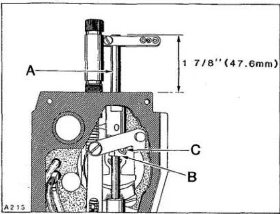
Insert a new set of needles. As a temporary setting, the TOP of needle bar (A, Fig. 7) should be approximately 1 7/8 inches (47.6mm) from the TOP of upper needle bar bushing when needle bar connection (B) is positioned at TOP of STROKE as shown in Figure 7.
NEEDLE BAR ALIGNMENT (Continued) (For Two and Three Needle Styles)
Adjustment can be made by loosening screw (C), reposition needle bar up or down as required and tighten screw (C) VERY LIGHTLY.
IMPORTANT: Refer to NOTE, page 9 for proper TORQUE of screw.
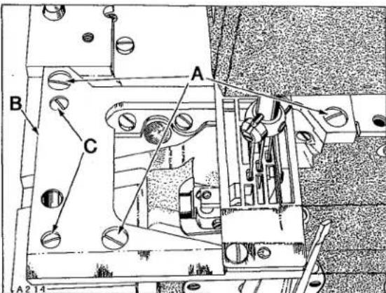
Rotate handwheel to ensure that needles center in the needle holes of throat plate as shown in Figure 8. Adjustment can be made by loosening screw (C, Fig. 7) slightly, allowing needle bar to be rotated as required, while being careful to maintain the temporary height setting and tighten screw (C) AS SPECIFIED. An additional 4-way directional adjustment of the throat plate can be accomplished as follows:
IMPORTANT: Adjustment of throat plate must be coordinated between needles and feed dog; refer to "FEED DOG SETTINGS". Loosen three screws (A, Fig. 8) in throat plate support (B). Loosen two screws (C) which secure locating ferrules, allowing the throat plate support to be repositioned slightly. Tighten screws (C) first, then screws (A).
CAUTION! Needle bar has a special coating. DO NOT wedge or pry with any type of tool, as damage to needle bar may result. Should needle head require assembling to needle bar, TORQUE 14-16 in-lbs (16-18 cm/kg).
LOOPER SETTING (For Single Needle Styles)
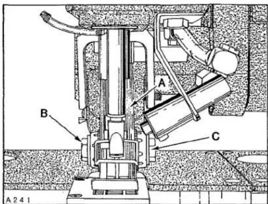
Insert a new needle, type and size specified. With looper positioned at EXTREME right end of travel, distance from centerline of needle to point of looper should be 5/32 inch (4.0mm). Adjustment can be made by loosening screw (A, Fig. 9) and turn screw (B) clockwise to increase looper gauge or counterclockwise to decrease. Apply pressure to the upper portion of looper holder (C) to the left while making this adjustment and locking with screw (A).
Looper gauge No. 21225-5/32 can be used advantageously while making this adjustment.
text_image
A 1 7/8'' (47.6mm) C B A215Fig. 7
text_image
A B C A 2 14Fig. 8

text_image
5/32" (4.0mm) A215 C B AFig. 9
LOOPER SETTING (Continued) (For Single Needle Styles)

text_image
A B C D A 216Fig. 10
Looper must also be set so, as it travels to the left behind the needle, NOT to touch, but with a MAXIMUM clearance of .002 inch (.051mm). Adjustment can be made by loosening screw (A) and moving looper holder (C) forward or rearward on its shaft to obtain specified conditions; apply pressure to the upper portion of looper holder to the left while tightening screw (A).
LOOPER SETTING (For Two and Three Needle Styles)
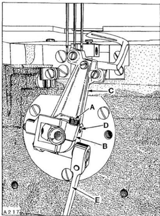
If not previously done, insert a new set of needles; type and size specified. With looper holder at EXTREME right end of travel, distance from centerline of RIGHT needle to point of RIGHT looper should be dimension (A, Fig. 10); see chart. Adjustment can be made by pulling release lever (B) down and loosening screw (A, Fig. 11) in stop collar (B). Apply pressure against the upper portion of looper holder (C) to the LEFT while turning screw (D) in looper holder clockwise to increase looper gauge or counterclockwise to decrease. Applicable looper gauge can be used advantageously in making this adjustment.
text_image
A 217 C A D B EFig. 11
Continue to apply pressure against upper portion of looper to the LEFT while turning stop collar (B) to its EXTREME CLOCKWISE position and tighten screw (A) securely. Push up release lever (E) to lock looper holder in position. Adjust screw (C, Fig. 10) which incorporates a spring plunger, against the recess in cam of stop collar as required to attain the following conditions:
Pull release lever down and be able to push looper holder to the right, with a snapping motion (making loopers easily accessible for threading). Push looper holder to the left, with a snapping motion. Apply pressure against upper portion of looper holder to the LEFT and push release lever up to lock looper holder in operating position.
In locked position, the release lever should be approximately in line with middle looper as viewed from the right side of looper holder. Adjustment can be made by loosening screw (D, Fig. 10), reposition release lever as required and retighten screw.
LOOPER SETTING (Continued) (For Two and Three Needle Styles)
Loopers must also be set so, as they travel to the left behind the needles, NOT to touch, but with a MAXIMUM clearance of .002 inch (.051mm). Adjustment can be made by pulling release lever down, loosening screw (A, Fig. 11) in stop collar (B) allowing looper holder to be moved forward or rearward on its shaft, as required. Apply pressure against upper portion of looper holder to the LEFT while turning stop collar (B) to its EXTREME CLOCKWISE position and tighten screw (A) securely and push release lever up in locking position. RECHECK looper gauge.

text_image
B 1/64" (.4mm) A D C A 2 16Fig. 12
| MACHINE STYLE | DIMENSION A FIG. 10 | LOOPER GAUGE NO. |
| XF512E100HB-1 | 5/32 inch (4.0mm) | 21225-5/32 |
| XF512E100MP-12 | 1/8 inch (3.2mm) | 21225-1/8 |
| XF512E100MP-16 | 1/8 inch (3.2mm) | 21225-1/8 |
| XF513E100HJ-8 | 5/32 inch (4.0mm) | 21225-5/32 |
| XF513E100HJ-9 | 5/32 inch (4.0mm) | 21225-5/32 |
| XF513E100HR-9 | 5/32 inch (4.0mm) | 21225-5/32 |
| XF513E101HR-9 | 5/32 inch (4.0mm) | 21225-5/32 |
| XF513E112HR-9 | 5/32 inch (4.0mm) | 21225-5/32 |
NEEDLE BAR HEIGHT
Turn handwheel in operating direction until POINT of looper (A, Fig. 12) is even with the LEFT side of needle (B). TOP of needle eye should be 1/64 inch (.4mm) below the under surface of looper blade, as shown in Figure 12. Adjustment can be made by loosening screw (C) and move needle bar (D) up or down as required.
IMPORTANT: Refer to NOTE, page 9 for proper TORQUE of screw.
NOTE: Needle bar has special coating. DO NOT wedge with any type of tool, as damage to needle bar may result.
IMPORTANT! Care must be taken not to disturb ALIGNMENT of needle bar while making this adjustment.
LOOPER AVOID
Machine is equipped with a quick adjustable looper avoid mechanism to accommodate extreme differences in needle sizes. As the looper travels from left to right with the needle bar descending, the needle point/s should contact ONLY the lower THIRD of the back of
text_image
A219 B AFig. 13
LOOPER AVOID (Continued)
text_image
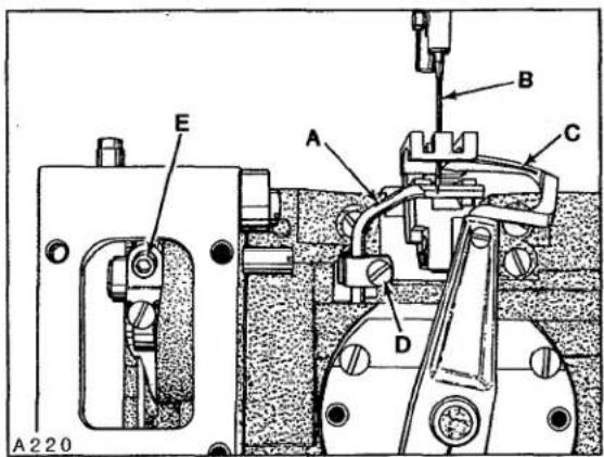
A 220 E A B C DFig. 14
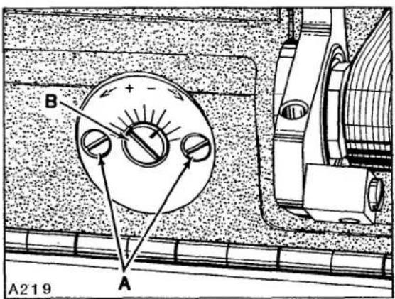
looper blade/s. Adjustment can be made by loosening two screws (A, Fig. 13) and turn eccentric stud (B) towards the plus side (counterclockwise) for MORE looper avoid or towards the minus side (clockwise) for LESS. When properly set, tighten screws (A).
NOTE: Whenever looper avoid is changed, ALWAYS recheck "LOOPER SETTINGS".
REAR NEEDLE GUARD
At extreme forward end of travel, rear needle guard (A, Fig. 14) must be set horizontally not to contact needle/s (B) with a maximum clearance of .002 inch (.051mm).
text_image
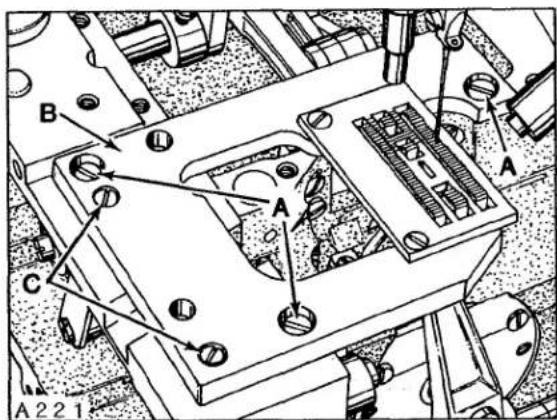
A B A C A221Fig. 15
Guard should be set as low as possible, yet have its vertical face approach approximately 3/64 inch (1.2mm) of needle point until point of looper (C) moving to the left, is even with the right side of needle. Adjustment can be made by loosening screw (D), reposition needle guard as required and retighten screw. If additional front to rear adjustment is required to maintain needle guard in a horizontal position, loosen screw (E) in pivot link which allows needle guard shaft to be rotated. Be sure to take up thrust by exerting pressure against needle guard holder to the left and pivot link to the right, while tightening screw (E).
NOTE: Change in stitch length WILL NOT require change in needle guard setting, but a change of needle size may.

text_image
C A B A222Fig. 16
FEED DOG SETTINGS
Feed dog should be centered in throat plate with equal clearance on both sides and ends. At highest point of travel, feed dog teeth should extend the depth of a tooth or approximately 3/64 inch (1.2mm) above throat plate. MINOR (right to left) adjustments can be made by loosening three screws (A, Fig. 15) in throat plate support (B). Loosen two screws (C) which secure two locating ferrules used to align throat plate support. Reposition slightly as required considering both needle hole slot/s and feed dog slots. Tighten screws (C) first, then screws (A).
FEED DOG SETTINGS (Continued)
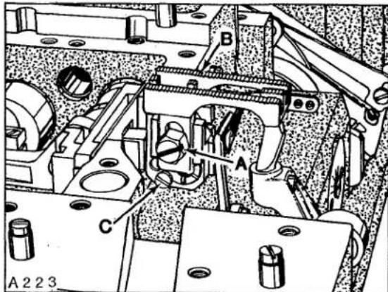
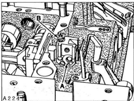
Front to rear adjustments can be made by loosening two screws (A, Fig. 16), reposition feed dog holder (B) as required. Press down on front of feed dog (C) while tightening screws (A). Feed dog can be leveled or tilted by removing throat plate, loosen two screws (A, Fig. 16) and screw (A, Fig. 17) so feed dog (B) can be raised enough to loosen locking screw (C).
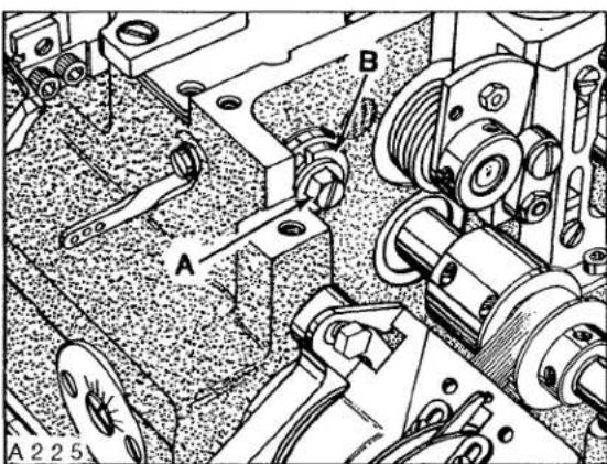
Turn feed tilting cam (A, Fig. 18) as required to level feed dog as it comes out of throat plate. Retighten screw (C, Fig. 17) and screws (A, Fig. 16) while pressing down on front end of feed dog. Adjust feed dog height supporting screw (B, Fig. 18) to support feed dog after specified feed dog height has been determined by checking with feed dog and throat plate in place. When adjustments are completed, tighten screw (A, Fig. 17) while pressing down in front of feed dog. More or less FEED LIFT can be acquired by loosening screw (A, Fig. 19) and turning adjusting dial (B) towards the operator to increase feed lift. Turning away from operator decreases. Retighten screw (A). Turn handwheel in operating direction to ensure that feed dog does not strike throat plate or looper/s, throughout its path of travel.
CHANGING STITCH LENGTH (All Styles except XF511B100MF)
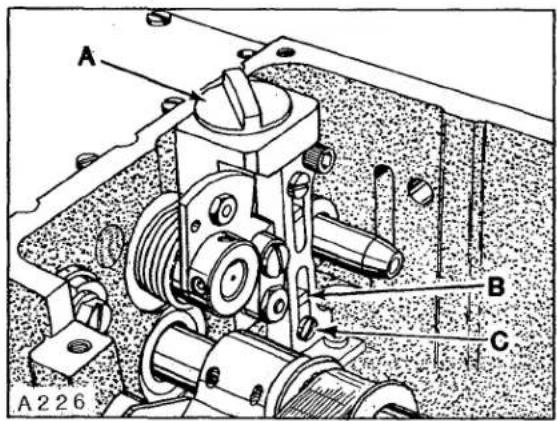
Stitch length can be changed by pressing down and turning stitch length regulating knob (A, Fig. 20) clockwise to shorten or counterclockwise to lengthen the stitch. Recheck front to rear clearances in throat plate as described under "FEED DOG SETTINGS" whenever stitch length is changed. Bottom limit stop (B) should be set by screw (C) to prevent regulating knob (A) from accidentally being turned beyond the desired maximum stitch length.
CHANGING STITCH LENGTH (For Style XF511B100MF)
Stitch length can be changed by loosening screw (A, Fig. 21) which is accessible through a slot in the right cloth plate (1/8 inch Allen wrench required). When moved towards the rear lengthens the stitch; moving
text_image
A 223 B A CFig. 17
natural_image
Technical mechanical assembly diagram showing components labeled A and B, with no readable text or symbols beyond labelsFig. 18
text_image
A B A 2 2 5Fig. 19
CHANGING STITCH LENGTH (Continued) (For Style XF511B100MF)
towards the front acts the reverse. Recheck front to rear clearances in throat plate as described under "FEED DOG SETTINGS" whenever stitch length is changed. Tighten screw (A) securely.
LOW INERTIA PRESSER FOOT (For Styles XF511B100MF, XF511E101MF, 118MF, 152MF, XF511H100MF, 100MG, 112MF, 112MG and 151MF)
text_image
A B C A 2 2 6Fig. 20
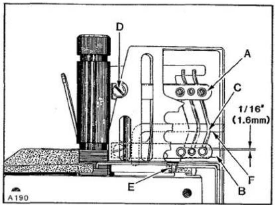
With needle bar at bottom of stroke and presser foot resting on throat plate, there should be 1/32 inch (.8mm) clearance between top of screw and top of slot in presser foot as viewed in Figure 22. There should be 1/16 inch (1.6mm) clearance between bottom of slot in lifter lever link (A) and bottom of presser bar guide (B) when foot lifter lever is released. If adjustment is required, loosen nut (C) and turn screw (D) down approximately 1/8 inch (3.2mm) below bottom surface of presser bar guide (B). Back off presser spring regulating screw and loosen screws (E) in presser bar guide (B) so that presser foot rests squarely on throat plate and screw (D) is touching the bottom of presser bar guide plate, then retighten screws (E).

natural_image
Technical line drawing of a mechanical assembly with labeled component A (no text or symbols beyond label)Fig. 21
Turn presser spring regulating screw all the way down, then back off screw (D) counterclockwise to obtain the 1/32 inch (.8mm) dimension in presser foot; lock nut (C). Loosen screw (F) in lifter arm (G) and rotate arm slightly as required to obtain the 1/16 inch (1.6mm) dimension between link (A) and guide (B); retighten screw (F) ensuring no left to right shake in lifter arm (G).
FEEDING PRESSER FOOT (For Style XF511H100MAW)
With presser foot resting on throat plate, the distance from top of spring (A, Fig. 23) to top of yoke (B) should be 5/8 inch (15.9mm) and the line stamped across the presser foot bottom should line up with centerline of needle. As the presser foot is raised, its bottom should move VERY SLIGHTLY towards the rear... 1/64 inch (.4mm) maximum. If adjustment is required, proceed as follows:
FEEDING PRESSER FOOT (Continued) (For Style XF511H100MAW)
Remove presser spring regulating screw, presser bar spring guide and presser bar spring. Loosen nut (C, Fig. 22) and turn screw (D) down approximately 1/8 inch (3.2mm) below bottom surface of presser bar guide (B). Loosen screws (E) in presser bar guide (B). Adjust spring regulator nut (C, Fig. 23) as required, so its lower surface is 5/8 inch (15.9mm) from top of yoke (B) as viewed in Figure 23. With presser foot resting on throat plate and feed dog down below throat plate, press down on spring regulator nut (C) until the marks in presser foot bottom align with centerline of needle and positioned to keep needle in center of needle slot. Tighten screws (E, Fig. 22) securing presser bar guide to presser bar, ensuring stop screw (D) in presser bar guide is resting on bottom of presser bar guide plate.
Replace presser bar spring, spring guide and spring regulating screw. Turn regulating screw down until the top of its threaded portion is level with head casting. Rotate handwheel to position feed below throat plate with presser foot resting on throat plate. Depress presser foot lifter lever to see if presser foot bottom moves SLIGHTLY towards the rear before presser foot begins to lift. Adjustment can be made by turning stop screw (D, Fig. 23) clockwise to shorten or counterclockwise to lengthen the distance of travel.
Loosen screw (F, Fig. 22) in lifter arm (G) and rotate arm slightly as required to obtain 1/16 inch (1.6mm) clearance between link (A) and guide (B); retighten screw (F) ensuring no left to right shake in lifter arm (G).

text_image
1/32" (.8mm) 1/16" (1.6mm) A G A D C B F E A 228Fig. 22
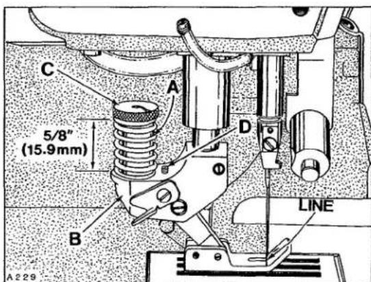
text_image
5/8" (15.9mm) A B C D LINE A 229Fig. 23
Presser foot, at back of needle slot should cover most of throat plate land when resting directly on throat plate.
When presser foot bottom is raised by material and the feeding foot spring bottoms, rear of needle slot should clear the needle. Main presser bar should not begin to lift before the spring of feeding foot bottoms.
Purpose of the feeding presser foot is to make top and bottom plies of material feed the same amount without pulling on the bottom ply. Final adjustment may be required to match plies; turning nut (C, Fig. 23) to increase pressure on spring (A) will tend to feed the bottom ply more... decreasing pressure will tend to feed the top ply more.
PRESSER BAR AND PRESSER FOOT (For Styles XF512E100HB, MP, XF513E100HJ, 100HR, 101HR and 112HR)

text_image
H C A F D B 1/16 inch (1.6mm) E G A230Fig. 24
With needle bar at bottom of stroke and presser foot resting squarely on throat plate, there should be a minimum clearance of 1/64 inch (.4mm) between the bottom of screw (A, Fig. 24) and bottom of slot in presser bar guide plate (B). At this time, there should be at LEAST 1/32 inch (.8mm) clearance between bottom of presser bar guide and top of lower presser bar bushing.
There should also be 1/16 inch (1.6mm) clearance between bottom of slot in lifter lever link (C) and bottom of presser bar guide (D) when foot lifter lever is released. If adjustment is required, proceed as follows:
Back off presser bar spring regulator to release tension on spring. Loosen two screws (E) in presser bar guide (D). Loosen nut (F) and turn screw (A) down against guide plate (B) to obtain at least 5/64 inch (2.0mm) clearance between bottom of presser bar guide (D) and guide plate (B). Align presser foot with needles and press down FIRMLY while tightening two screws (E) in presser bar guide (D).
NOTE: This setting was necessary to prevent damage to the scraper edge of presser bar bushing, should presser foot be removed from machine.

text_image
A B C A 2 3 1Fig. 25
Turn presser bar spring regulator down. Back off screw (A) to obtain the 1/64 inch (.4mm) dimension between bottom of screw and bottom of slot in presser bar guide plate (B), lock nut (F).
Loosen screw (G) in lifter arm (H) and rotate arm slightly as required to obtain the 1/16 inch (1.6mm) dimension between link (C) and guide (D), retighten screw (G) ensuring no left to right shake in lifter arm (H).
Adjust presser bar spring regulator so it exerts only enough pressure on presser foot to feed the work uniformly. Turning it clockwise increases the pressure, counterclockwise acts the reverse.
THREAD TENSION RELEASE
Needle thread tension assembly (A, Fig. 25) is set correctly when the tension discs (B) begin to release thread as the presser foot is raised to within 1/8 inch (3.2mm) from the end of its travel and completely released when presser foot has
reached its highest position. Adjustment can be made by loosening screw (C) and lower the tension assembly (A) to advance the release action or raise tension assembly to retard the release action. Hold tension assembly in desired position while retightening screw (C).
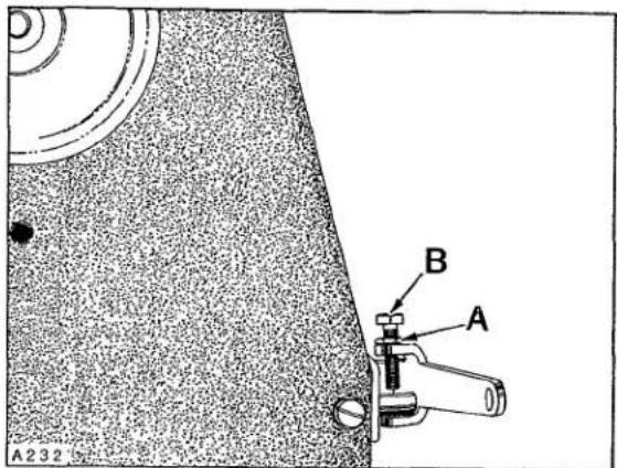
Loosen lock nut (A, Fig. 26) and adjust screw (B) in presser foot lifter lever, allowing presser foot to be raised to its highest position without interfering with needle head. Lock nut (A) securely.
LOOPER THREAD TAKE-UP AND CAST-OFF PLATE
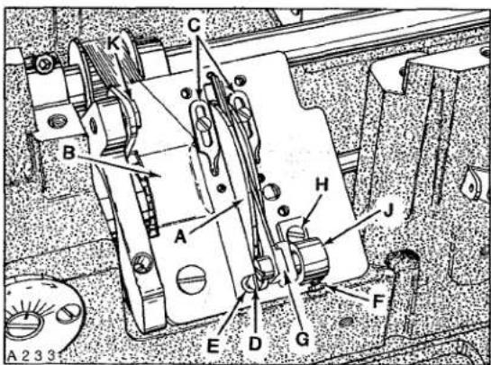
Looper thread take-up (A, Fig. 27) should be centered, left to right, in cast-off plate (B). As the needle bar is descending, the take-up should be in position to cast-off looper thread just as the tip of needle is even with the bottom of looper. Adjustment can be made by loosening two screws in take-up (through access hole in cast-off plate), reposition take-up as required and retighten screws. Set adjustable eyelets (C) 1/2 inch (12.7mm) below centerline of their mounting screws.
If cast-off wire is rubbing take-up, loosen screw (D), center the wire (E) and retighten screw. If retaining finger is rubbing take-up, loosen screw (F), center the finger (G) and retighten screw. If retaining finger is on an angle, loosen screw (H), turn retaining finger support (J) slightly as required and retighten screw. Height of cast-off plate is set correctly when the lowest point of take-up cam is even with the top surface of cast-off plate. Adjustment can be made by turning handwheel in operating direction to locate the lowest point of the take-up cam, loosen screw (K) and raise or lower cast-off plate to correct height; then tighten screw (K) securely.
text_image
A232 B AFig. 26
text_image
Technical diagram of a mechanical device with labeled components A through J, showing internal components and assembly lines.Fig. 27
THREAD CONTROL SETTINGS
(For Styles XF511B100MF, XF511E101MF, 118MF, 152MF, XF511H100MF, MG, MAW, 112MF, 112MG and 151MF)
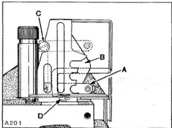
Needle bar eyelet (A, Fig. 28) and needle thread cam (B) should be set in conjunction with each other so needle thread just contacts needle thread cam (B) at TOP and BOTTOM of stroke.
Adjustments can be made by bringing needle bar up, loosen screw (C) slightly, reposition eyelet (A) up or down as required. TORQUE screw (C) to 10 in-lbs. (11.5 cm/kg). Needle thread cam can be adjusted forward or rearward as required by loosening needle thread cam mounting screw (D) and retighten screw. Loosen screw (A, Fig. 29) and position strike-off wire (B) 1/2 inch (0.5mm) from top surface of top cover to underside of strike-off wire. With needle bar at BOTTOM of stroke and Thread Control Assembly adjustable eyelet (C) set at "T". Apply necessary tension to both needle and looper-thread and start to sew. Looper thread tension should be light. Adjust needle thread tension to pull up smallest needle loop as required. At this point a tight stitch will be achieved. Without changing needle thread tension move Thread Control Assembly adjustable eyelet to "L". This will produce a loose seam with longer needle loops.
NOTE: Adjustment of strike-off wire can be raised to accommodate thick dense material.
text_image
C B A D A201Fig. 28
THREAD CONTROL SETTINGS
(For Styles XF512E100HB, MP, XF513E100HJ HR, 101HR and 112HR)
Needle bar eyelet (A, Fig. 30) should be set with its eyelets 1/16 inch (1.6mm) below strike-off (B) on needle thread take-up cam wire (C) as shown in Figure 30, with needle bar at BOTTOM of stroke.
Adjustments can be made by bringing needle bar up, loosen screw (D) slightly, bring needle bar down to BOTTOM of stroke, reposition eyelet (A) as required and bring needle bar up. TORQUE screw (D) to 10 in-lbs. (11.5 cm/kg).

text_image
C L11231 T B A 1/2 (0.5mm) A250 Union SFig. 29
Needle thread take-up cam wire (C) should be set to barely contact needle threads with needle bar at top of stroke. Adjustment can be made by loosening cam mounting screw (E), reposition cam forward or rearward as required and retighten screw. Auxiliary strike-off (F) should be set so needle threads contact strike-off when needle bar is at BOTTOM of stroke with Thread Control Assembly adjustable eyelet (C, Fig. 29) set at "T". Loosen screw (A) and position strike-off (B) as specified and retighten screw. Thread tension on needle thread should be just enough to pull up uniform stitches. Thread tension applied on looper thread should be just enough to steady thread.
POWER "AIR-KLIPP" CHAIN CUTTER ADJUSTMENTS
NOTE: References to Fig. 31 are as viewed from rear of machine; references to Fig. 32 are as viewed from left end of machine.
Upper knife (A, Fig. 31) can be replaced by removing two screws (B). In order to replace lower knife... the upper knife, rear cover and thread inlet must be removed. Lower knife (C) is held in position by roll pin (A, Fig. 32) and tension spring (D, Fig. 31). To remove lower knife, lift up and tilt to the right. When replacing lower knife, be sure to engage end of tension spring through the hole in the side of lower knife before inserting in the slide block (E). Also be sure that the slot in lower knife is located over roll pin.
SETTING KNIFE CROSS OVER
Adjustment will be necessary after replacing or repairing knives. With sewing motor switch in "OFF" position and air line connected to air motor, depress treadle until air motor begins to operate.
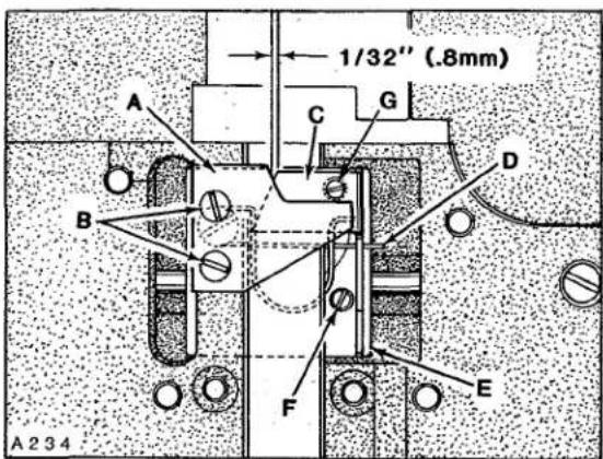
IMPORTANT! Be sure that lower knife does NOT strike against knife housing or feed chamber cover. Adjustment should be accomplished by loosening one screw (F, Fig. 31) and reposition left or right slightly.
Carefully press against slide block (E, Fig. 31) until air motor stalls.
With treadle still depressed, check the knife cross over. The cross over of the lower knife to the upper knife is positioned correctly, when the lower knife is 1/32 inch (.8mm) from the front of the upper knife as shown in Figure 31. If adjustment is required, loosen screw (F), reposition slide block (E) slightly as required. Retighten screw (F) and recheck cross over.
SHEAR ANGLE ADJUSTMENT
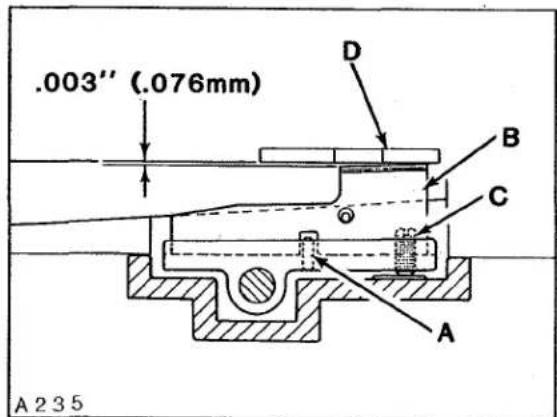
Shear angle should be .003 inch (.076mm), measured at rear cutting edge of lower knife (B, Fig. 32) and cutting edge of upper knife (D).
Adjustment can be made by turning lower knife adjusting screw (C, Fig. 32) counterclockwise (a small amount at a time) while manually
text_image
A 190 D A C 1/16" (1.6mm) E F BFig. 30
text_image
1/32" (.8mm) A C G B D F E A 234Fig. 31
text_image
.003'' (.076mm) A 235 D B C AFig. 32
text_image
A236 A BFig. 33
operating slide block (E, Fig. 31) continuously checking with a piece of thread to see if knives are cutting. As soon as the knives fail to cut the thread and the shear angle is zero, turn screw (C, Fig. 32), same as (G, Fig. 31) clockwise approximately 1/4 turn. Check cutting action of knives with sewing motor switch "ON".
SETTING PRESSURE VALVES
Regulate valve on pneumatic control devices for air motor of the "AIR-KLIPP" Chain Cutter to approximately 20-22 p.s.i. (1.5 bar) when air motor is operating. Regulate valve on pneumatic control device for the suction air to obtain maximum suction, yet so that the FABRIC TO BE SEWN will not be cut by the "AIR-KLIPP" Chain Cutter knives.
PULLER TIMING

text_image
A B A D C A237Fig. 34
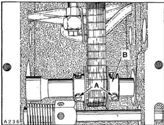
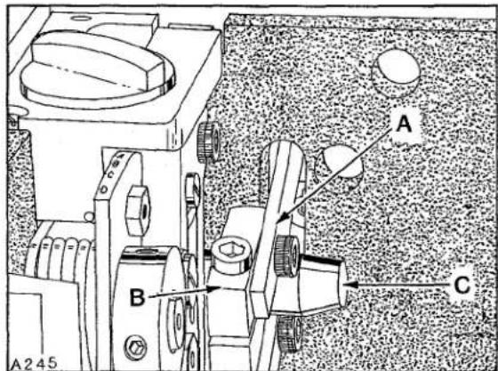
The Close-Coupled Puller (BELT or ROLLER) must be timed so the intermittent feeding action stops before the needle/s is/are entering the work. NOTE: This will depend on the thickness of material and stitch length being sewn. If adjustment is required, remove top cover which is secured with four screws. Loosen four set screws (A, Fig. 33) in sprocket (B). Advance or retard sprocket on shaft as required. When proper timing is obtained, position sprocket on its shaft (left or right) so drive belt is centered in the puller drive assembly. Torque four screws (A) to 35 in-lbs (40 cm/kg).
There should be approximately 1/8 inch (3.2mm) deflection in puller drive belt (A, Fig. 34) when pressing firmly between sprocket (B) and puller drive assembly. Adjustment can be made by loosening one screw (C) securing eccentric (D) and rotate eccentric counterclockwise as viewed in Figure 34, to tighten belt, clockwise acts the reverse. Be sure to maintain .006-.010 inch (.150-.254mm) between eccentric and drive housing. Tighten screw (C) securely. Replace top cover and tighten four screws.
The feeding motion of the puller is achieved by two sprockets. By using various combinations of nine different sprockets, (59) different puller stitch lengths can be obtained. Refer to sprocket charts on Page 28 that list the various sprocket combinations. NOTE: Actual stitch length may vary slightly due to material being sewn. When ordering sprockets use the appropriate dash number. Example: C50042-Z-( ).
To change sprockets loosen two screws (A, Fig. 35) and position screws to top of bracket to release tension on stitch length drive belt. NOTE: Belt guard has been removed for clarity. With drive belt in relaxed position, sprocket (B and C) can be removed. When installing sprockets (B and C) make sure that hub of sprocket is flush with end of shaft and 1st screw in operating direction is on the flat of shaft. Reassemble drive belt, tighten 2nd screw in sprockets (B and C) securely. Rotate handwheel in operating direction to make sure belt does not bind within belt guard. It may be necessary to reposition sprockets (B and C) slightly (left or right). Pull down firmly on puller assembly, making sure puller roller is setting evenly on Idler Roller and tighten two screws (A) securely.
The roller puller belt, which is located under hinged belt guard (D) should have 1/8 inch (3.2mm) deflection when pressing firmly between drive sprockets. If adjustment is required loosen two allen screws (A, Fig. 36) and turn eccentric shaft (B) slightly to apply tension on belt. Turning shaft clockwise tightens belt counterclockwise acts the reverse. CAUTION! Care must be taken not to disturb eccentric shaft (left or right). Tighten two screws (A) securely.
Belt Puller (A, Fig. 37) must be setting evenly on cloth plate (B). On Style XF511E152MF Belt Puller will rest on "AIR-KLIPP" inlet.

text_image
A23B B C D AFig. 35

text_image
A B A239Fig. 36

text_image
A A140 BFig. 37
text_image
A B C A 2 4 1Fig. 38
text_image
A242 A BFig. 39
text_image
G B 1/32 A C E D F S A243Fig. 40
PULLER STITCH LENGTH (Continued)
Belt puller drive belt (A, Fig. 38) should have approximately 1/8 inch (3.2mm) deflection when pressing firmly between drive sprockets. If adjustment is required hold lock nut (B) and loosen lock nut (C). Turn nut (B) to apply tension. Hold nut (B) firmly and tighten nut (C) securely.
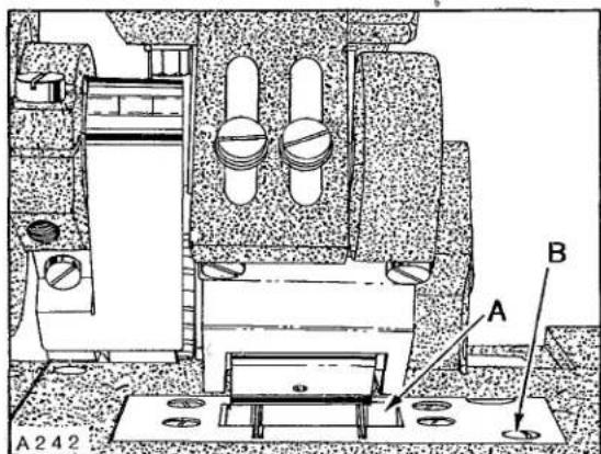
IDLER ROLLER
Puller Roller must be set evenly on Idler Roller (A, Fig. 39) to ensure that the material will be pulled straight through the sewing area. Adjustment for feeding can be made by shimming Idler Roller if necessary to achieve even mating. To shim roller remove one screw (B, Fig. 39) securing roller assembly. Remove Idler Roller Assembly and add shims as necessary between plate and bearing blocks to ensure even mating between Puller Roller and Idler Roller.
PULLER LIFT ADJUSTMENT
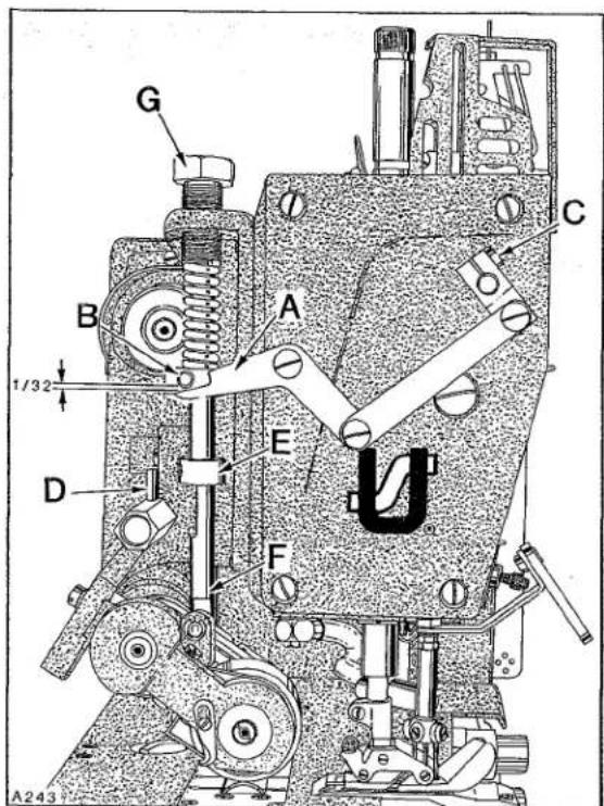
With puller in operating position and presser foot resting on throat plate there should be 1/32 inch (.8mm) between puller lifter link (A, Fig. 40) and puller lifting pin (B). If adjustment is required loosen screw (C) in upper presser foot lifting shaft connection and raise or lower link (A) as required. Tighten connection screw (C) securely.
NOTE: When presser foot starts to lift, puller must lift at the same time.
For sewing operations not requiring puller action the machine can be run with puller raised off the material by turning the manual lock-up pin (D) up to position under stop collar (E). If the puller has insufficient clearance to clear material, stop collar (E) can be raised or lowered on tension shaft (F)
PULLER LIFT ADJUSTMENT (Continued)
to suit. Adjust puller tension regulator (G) so it exerts only enough pressure on puller to feed work. Turning regulator clockwise to increase the presser, counterclockwise acts the reverse. If material does not pull straight through behind presser foot adjust main stitch length slightly so material will lay flat, until material is straight.
STITCH SHORTENING DEVICE
Stitch shortening device is set at the factory to produce one-half of the recommended stitch length per inch. If adjustment is required loosen lock screw (A, Fig. 41) and turn stop screw (B) clockwise for less stitches per inch, counterclockwise gives more stitches per inch.
The connecting arm (A, Fig. 42) is connected to the collar adaptor (B) located on the feed rocker shaft (C). The connecting arm (A) activates the feed rocker shaft to achieve the desired stitch length depending on operation.
text_image
A B C A245Fig. 40

text_image
B A A244Fig. 41
This chart shows the stitch length produced by available sprocket combinations. Sprockets furnished in the machines produces approximately 9.2 S.P.I. If a different length is required, refer to the chart for appropriate dash number when ordering sprockets-C50042-Z-( ).
Belt Puller Sprocket Variations
| DRIVEN SPROCKET PART NUMBER | NUMBER OF STITCHES PER INCH | ||||||||
| 13.10 SPI(1.94mm) | 11.92 SPI(2.13mm) | 10.92 SPI(2.33mm) | 10.08 SPI(2.52mm) | 9.37 SPI(2.71mm) | 8.74 SPI(2.91mm) | 8.19 SPI(3.10mm) | 7.71 SPI(3.29mm) | ||
| 12.37 SPI(2.05mm) | 11.26 SPI(2.26mm) | 10.31 SPI(2.46mm) | 9.52 SPI(2.67mm) | 8.84 SPI(2.87mm) | 8.25 SPI(3.08mm) | 7.73 SPI(3.28mm) | 7.28 SPI(3.49mm) | 6.88 SPI(3.69mm) | |
| 11.65 SPI(2.18mm) | 10.60 SPI(2.40mm) | 9.71 SPI(2.62mm) | 8.96 SPI(2.83mm) | 8.33 SPI(3.05mm) | 7.77 SPI(3.27mm) | 7.28 SPI(3.49mm) | 6.86 SPI(3.70mm) | 6.48 SPI(3.92mm) | |
| 9.94 SPI(2.56mm) | 9.10 SPI(2.79mm) | 8.40 SPI(3.02mm) | 7.81 SPI(3.25mm) | 7.28 SPI(3.49mm) | 6.83 SPI(3.72mm) | 6.43 SPI(3.95mm) | 6.07 SPI(4.19mm) | ||
| 8.49 SPI(2.99mm) | 7.84 SPI(3.24mm) | 7.28 SPI(3.49mm) | 6.79 SPI(3.74mm) | 6.37 SPI(3.99mm) | 6.00 SPI(4.24mm) | 5.66 SPI(4.49mm) | |||
| 7.28 SPI(3.49mm) | 6.77 SPI(3.75 mm) | 6.31 SPI(4.02mm) | 5.92 SPI(4.29mm) | 5.57 SPI(4.56mm) | 5.26 SPI(4.83mm) | ||||
| 6.24 SPI(4.07mm) | 5.83 SPI(4.30mm) | 5.46 SPI(4.65mm) | 5.14 SPI(4.94mm) | 4.86 SPI(5.23mm) | |||||
| 5.34 SPI(4.76mm) | 5.00 SPI(5.08mm) | 4.71 SPI(5.39mm) | 4.45 SPI(5.71mm) | ||||||
| 4.55 SPI(5.58mm) | 4.29 SPI(5.92mm) | 4.05 SPI(6.27mm) | |||||||
| -10 | -11 | -12 | -13 | -14 | -15 | -16 | -17 | -18 | |
| -10 | -11 | -12 | -13 | -14 | -15 | -16 | -17 | -18 | |
Roller Puller Sprocket Variations
| DRIVEN SPROCKET PART NUMBER | NUMBER OF STITCHES PER INCH | ||||||||
| 14.69 SPI(1.73mm) | 13.37 SPI(1.90mm) | 12.25 SPI(2.07mm) | 11.30 SPI(2.25mm) | 10.50 SPI(2.42mm) | 9.80 SPI(2.59mm) | 9.18 SPI(2.77mm) | 8.65 SPI(2.94mm) | ||
| 13.87 SPI(1.83mm) | 12.62 SPI(2.01mm) | 11.56 SPI(2.20mm) | 10.67 SPI(2.38mm) | 9.91 SPI(2.56mm) | 9.25 SPI(2.75mm) | 8.67 SPI(2.93mm) | 8.16 SPI(3.11mm) | 7.71 SPI(3.30mm) | |
| 13.06 SPI(1.94mm) | 11.88 SPI(2.13mm) | 10.89 SPI(2.53mm) | 10.05 SPI(2.53mm) | 9.34 SPI(2.72mm) | 8.71 SPI(2.92mm) | 8.16 SPI(3.11mm) | 7.69 SPI(3.30mm) | 7.26 SPI(3.50mm) | |
| 11.14 SPI(2.28mm) | 10.21 SPI(2.49mm) | 9.42 SPI(2.70mm) | 8.75 SPI(2.90mm) | 8.16 SPI(3.11mm) | 7.65 SPI(3.32mm) | 7.21 SPI(3.52mm) | 6.80 SPI(3.73mm) | ||
| 9.52 SPI(2.67mm) | 8.76 SPI(2.89mm) | 8.16 SPI(3.11mm) | 7.62 SPI(3.33mm) | 7.14 SPI(3.56mm) | 6.72 SPI(3.78mm) | 6.35 SPI(4.00mm) | |||
| 8.16 SPI(3.11mm) | 7.59 SPI(3.35 mm) | 7.08 SPI(3.59mm) | 6.63 SPI(3.83mm) | 6.25 SPI(4.07mm) | 5.90 SPI(4.31mm) | ||||
| 7.00 SPI(3.63mm) | 6.53 SPI(3.89mm) | 6.12 SPI(4.15mm) | 5.76 SPI(4.41mm) | 5.44 SPI(4.67mm) | |||||
| 5.98 SPI(4.24mm) | 5.61 SPI(4.53mm) | 5.28 SPI(4.81mm) | 4.99 SPI(5.09mm) | ||||||
| 5.10 SPI(4.98mm) | 4.81 SPI(5.28mm) | 4.54 SPI(5.60mm) | |||||||
| -10 | -11 | -12 | -13 | -14 | -15 | -16 | -17 | -18 | |
| DRIVE SPROCKET PART NUMBER | |||||||||
natural_image
Technical line drawing of a mechanical assembly with gears, springs, and housing (no text or labels)EXPLODED VIEWS
AND
DESCRIPTION OF PARTS

text_image
TORQUE TO 28 in. 1bs. (32 cm/kg) TORQUE TO 19-21 in. 1bs. (22-24 cm/kg) TORQUE TO 16-18 in. 1bs. (18-21 cm/kg) TORQUE TO 16-18 in. 1bs. (18-21 cm/kg)LUBRICATION PARTS
| Ref.No. | PartNo. | Description | Amt.Req. |
| 1 | C50093 CG | Oil Syphon Assembly | 1 |
| 2 | C50093 CH | Tube, syphon drain | 1 |
| 3 | C50093 CJ | Tube, oil return | 1 |
| 4 | C50093 CL | Fitting, barb | 1 |
| 5 | 56322 B | Gasket | 2 |
| 6 | 671 F-4 | Fitting, barb | 1 |
| 7 | 79-31 | Ball, steel | 1 |
| 8 | C50093 CM | Manifold, oil syphon | 1 |
| 9 | 22730 | Screw | 1 |
| 10 | 50393 AX | Tube, oil return | 1 |
| 11 | 50393 DC | Oil Return Tube Assembly | 1 |
| 12 | 671 F-41 | Tee, union | 1 |
| 13 | 50393 AY | Tube, sleeve | 1 |
| 14 | 666-322 | Felt | 1 |
| 15 | 50393 CU | Tube, oil return | 1 |
| 16 | 50393 CS | Spring, tube retainer | 1 |
| 17 | 50393 CY | Tube, oil return | 1 |
| 18 | 50393 V | Retainer, wire (oil tube) | 1 |
| 19 | 660-220 | "0" Ring | 5 |
| 20 | 22652 B-12 | Screw | 4 |
| 21 | 660-885 | Clamp, oil tube | 1 |
| 22 | C50094 P | Tube, oil | 4 |
| 23 | 660-683 | "0" Ring | 5 |
| 24 | 73 | Screw | 2 |
| 25 | C50094 G | Screen, oil filter | 1 |
| 26 | C50094 AM | Screen, oil | 1 |
| 27 | C50094 F | Strainer, oil | 1 |
| 28 | C50094 V | Tube, oil | 1 |
| 29 | 22720 B | Screw, oil connection | 2 |
| 30 | C50094 U | Connection, oil, single feed | 2 |
| 31 | C50094 C | Connection, oil, single feed | 7 |
| 32 | C50094 Y | Tube, oil | 1 |
| 33 | RI-37 | Ring, wire | 6 |
| 34 | C50093 BX | Valve, check | 1 |
| 35 | C50094 AA | Tube, oil | 1 |
| 36 | 22720 A | Screw, oil connection | 8 |
| 37 | C50094 Z | Tube, oil | 1 |
| 38 | C50094 B | Connection, oil, double feed | 1 |
| 39 | RM3728-1 | Fitting, oil | 1 |
| 40 | C50094 R | Tube, oil | 1 |
| 41 | C50093 BE | Nut | 2 |
| 42 | 660-750 | Sleeve, compression | 2 |
| 43 | 660-749 | Nut, compression | 2 |
| 44 | C50094 AC | Tube, oil | 1 |
| 45 | C50093 CV | Valve, priority | 1 |
| 46 | 660-855 | Connector, compression | 1 |
| 47 | 671 C-4 | Connector, male | 1 |
| 48 | C50094 | Tube, oil | 1 |
| 49 | 666-294 | Elbow, male | 2 |
| 50 | 670 E-2 | Tie, cable; to secure Ref. No. 2 to Ref. No. 48 | 1 |
| 51 | 671 F-41 | Tee, union | 1 |
| 52 and 53 | See Following Page | ||
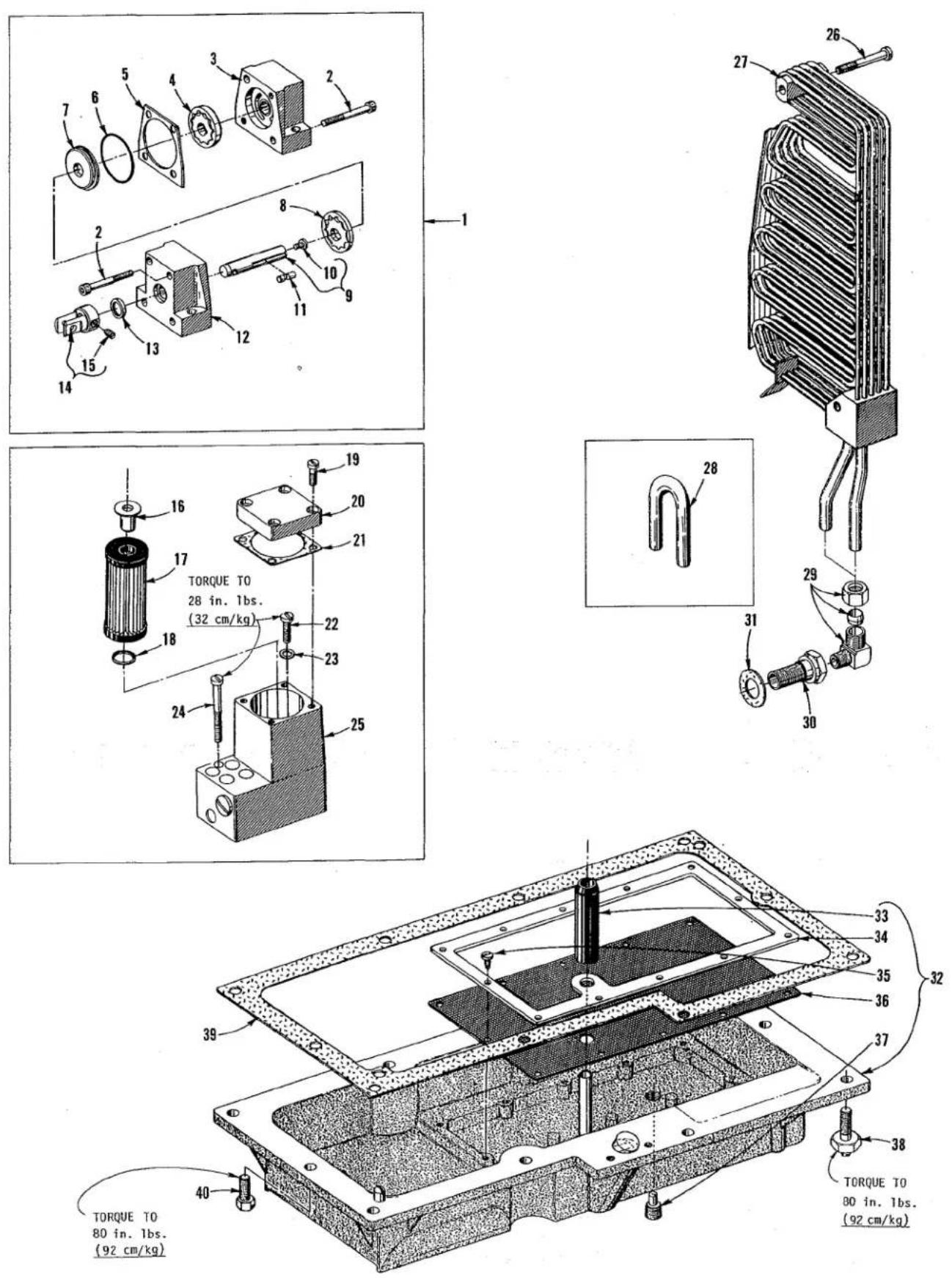
OIL PAN AND LUBRICATION PARTS
| Ref. No. | Part No. | Description | Amt. Req. |
| 1 | C50093 L | Oil Pump Assembly | 1 |
| 2 | 22652 A-20 | Screw | 4 |
| 3 | C50093 M | Housing, pump (pressure) | 1 |
| 4 | C50093 U | Gerotor, 1/4 inch (6.4mm) thick | 1 |
| 5 | C50093 T | Divider, housing | 1 |
| 6 | 660-684 | "0" Ring | 1 |
| 7 | C50093 S | Spacer, housing | 1 |
| 8 | C50093 R | Gerotor, 1/8 inch (3.2mm) thick | 1 |
| 9 | C50093 P | Shaft | 1 |
| 10 | 22784 E | Screw | 1 |
| 11 | C50093 Z | Pin, dowel | 1 |
| 12 | C50093 N | Housing, pump (suction) | 1 |
| 13 | 660-739 | Seal, lip | 1 |
| 14 | C50093 BS | Coupling | 1 |
| 15 | 22764 | Screw, spot | 1 |
| 16 | C50093 CB | By-Pass, oil filter | 1 |
| 17 | C50093 CA | Filter, oil | 1 |
| 18 | 660-206 | "0" Ring | 1 |
| 19 | 22541 | Screw | 4 |
| 20 | C50093 F | Cover | 1 |
| 21 | C50093 G | Gasket | 1 |
| 22 | 22541 C | Screw | 1 |
| 23 | 56322 B | Gasket | 1 |
| 24 | 22851 A | Screw | 1 |
| 25 | C50093 | Manifold, flow control | 1 |
| 26 | 22592 B | Screw, for Styles XF511H100MF, MG, MAW, 112MF, 112MG and 151MF | 2 |
| 27 | C50093 AN | Cooler, oil; for Styles XF511H100MF, MG, MAW, 112MF, 112MG and 151MF | 1 |
| 28 | C50094 W | By-Pass, tube, oil cooler; all Styles except XF511H100MF, MG, MAW, 112MF, 112MG and 151MF | 1 |
| 29 | 666-294 | Elbow, male | 2 |
| 30 | C50093 AJ | Fitting, adaptor | 2 |
| 31 | C50093 BH | Gasket | 2 |
| 32 | C50093 AA | Pan, oil | 1 |
| 33 | C50093 AE | Sleeve, stand pipe | 1 |
| 34 | C50093 AG | Plate, filter | 1 |
| 35 | 22569 C | Screw | 12 |
| 36 | C50093 AH | Screen, filter | 1 |
| 37 | 22571 E | Screw, oil drain plug (magnetic) | 2 |
| 38 | C50095 | Screw | 8 |
| 39 | C50093 AB | Gasket | 1 |
| 40 | 22881 B | Screw | 2 |
text_image
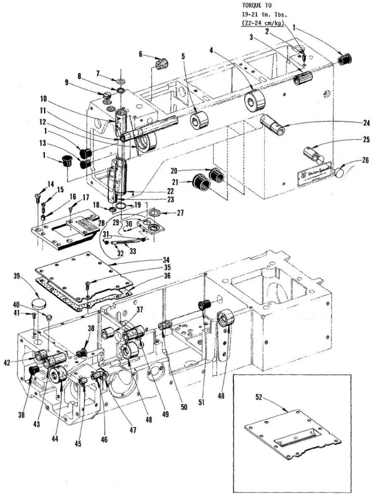
TORQUE TO 19-21 in. 1bs. (22-24 cm/kg) 2 3 1 24 25 26 5 4 6 7 8 9 10 11 12 13 14 15 16 17 18 19 20 21 22 23 24 25 Union Sensor 30 31 32 33 34 35 36 37 38 39 40 41 42 43 44 45 46 47 48 49 50 51 52 53MAIN FRAME BUSHINGS AND PLUGS
| Ref.No. | PartNo. | Description | Amt.Req. |
| 1 | C50093 AY | Plug, oil ---- | 3 |
| 2 | 22894 K | Screw ---- | 1 |
| 3 | C50090 K | Bushing, presser foot lifter lever (right) ---- | 1 |
| 4 | C50055 S | Bushing, upper mainshaft (right) ---- | 1 |
| 5 | C50055 L | Bushing, upper mainshaft (center) ---- | 1 |
| 6 | C067 H | Plug, cork ---- | 1 |
| 7 | C50054 D | Shield, needle bar bushing ---- | 1 |
| 8 | 666-311 | Screen, needle bar bushing ---- | 1 |
| 9 | 22539 G | Screw, plug ---- | 1 |
| 10 | 50354 D | Bushing, needle bar (upper) ---- | 1 |
| 11 | C50090 E | Bushing, presser foot lifter lever (left) ---- | 1 |
| 12 | C50055 K | Bushing, upper mainshaft (left) ---- | 1 |
| 13 | C50093 CT | Plug, oil ---- | 1 |
| 14 | 22839 | Screw ---- | 3 |
| 15 | 22587 N | Screw ---- | 2 |
| 16 | C50080 B | Ferrule, locating ---- | 2 |
| 17 | 87 | Screw, all Styles except XF512E100HB-1, MP-12, MP-16,XF513E100HJ-8, HJ-9, HR-9, 101HR-9 and 112HR-9 ---- | 2 |
| XF513E100HJ-8, HJ-9, HR-9, 101HR-9 and 112HR-9 ---- | 2 | ||
| - | 22570 | Screw, for Styles XF512E100HB-1, MP-12, MP-16, XF513E100HJ-8,HJ-9, HR-9, 101HR-9 and 112HR-9 ---- | 2 |
| 18 | 660-739 | Seal, oil, presser bar bushing ---- | 1 |
| 19 | 661-1 | "0" Ring, needle bar bushing (lower) ---- | 1 |
| 20 | C50093 AW | Plug, oil ---- | 1 |
| 21 | C50093 AX | Plug, oil ---- | 1 |
| 22 | 50354 E | Bushing, needle bar (lower) ---- | 1 |
| 23 | C50057 D | Bushing, presser bar ---- | 1 |
| 24 | C50090 F | Bushing, presser foot lifter lever (rear) ---- | 1 |
| 25 | C50090 G | Bushing, presser foot lifter lever (front) ---- | 1 |
| 26 | 51-627 BLK | Plug ---- | 1 |
| 27 | 666-32 | Felt, oil return ---- | 1 |
| 28. | 50393 DD | Needle Bar Oil Collector Plate Assembly ---- | 1 |
| 29 | 50393 CX | Plate, oil collector ---- | 1 |
| 30 | 22733 | Screw ---- | 1 |
| 31 | 50393 CS | Spring, tube retainer ---- | 2 |
| 32 | 50393 CV | Tube, oil return ---- | 1 |
| 33 | 50393 CZ | Spring ---- | 1 |
| 34 | C50082 D | Cover, feed chamber; all Styles except XF511E101MF,XF511E152MF, XF513E101HR-9, XF513E112HR-9,XF511H112MF, 112MG and 151MF ---- | 1 |
| 35 | 22569 G | Screw ---- | 10 |
| 36 | C50082 E | Gasket ---- | 1 |
| 37 | C50036 J | Bushing, feed rocker shaft (right) ---- | 1 |
| 38 | C50035 Z | Plug ---- | 2 |
| 39 | C50051 X | Plug, stitch adjustment hole ---- | 1 |
| 40 | C50049 A | Window, stitch indicator (left) ---- | 1 |
| 41 | 22521 | Screw, plug ---- | 1 |
| 42 | C50036 U | Bushing, feed rocker shaft (left) ---- | 1 |
| 43 | C50035 Y | Bushing ---- | 1 |
| 44 | C50044 F | Bushing, feed drive shaft (left) ---- | 1 |
| 45 | C50068 AG | Bushing, rear needle guard shaft (left) ---- | 1 |
| 46 | C50068 X | Bushing, rear needle guard shaft (right) ---- | 1 |
| 47 | C50044 D | Bushing, looper rocker shaft ---- | 1 |
| 48 | C50044 G | Bushing, feed drive shaft (right) and lower mainshaft(left) ---- | 2 |
| 49 | C50035 G | Bushing, stitch control shaft ---- | 1 |
| 50 | C067 F | Plug, cork ---- | 1 |
| 51 | C50093 DB | Plug, oil ---- | 1 |
| 52 | C50082 DA | Cover, feed chamber; for Styles XF511E101MF andXF513E101HR-9 ---- | 1 |
text_image
TORQUE TO 28 in. 1bs. (32 cm/kg) 12 11 10 6 7 5 4 3 2 1 13 14 15 16 17 19 18 20 21 22 23 24 25 26 27 28 29 30 31 32 33 34 35 36 37 38 39 40 41 42 43 44 45 46 47 48 50 51 52 53P163
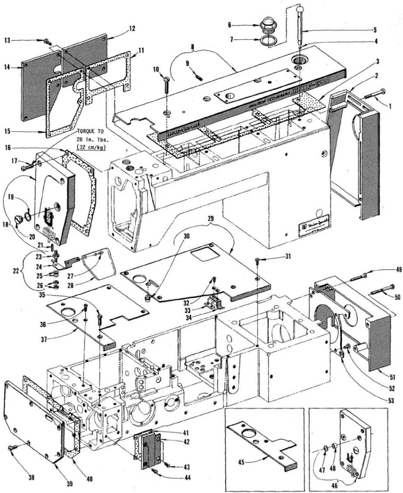
SAFETY SHEILD, COVERS AND CLOTH PLATES
| Ref.No. | PartNo. | Description | Amt.Req. |
| 1 | 22851 D | Screw ---- | 4 |
| 2 | C50082 L | Cover, oil cooler ---- | 1 |
| 3 | C50082 T | Gasket ---- | 1 |
| 4 | 21192 R | Ball, steel ---- | 1 |
| 5 | C50093 AS | Indicator, oil flow ---- | 1 |
| 6 | C50093 AU | Cap, oil filler ---- | 1 |
| 7 | C50082 X | Gasket ---- | 1 |
| 8 | C50082 U | Cover, top for single needle machines ---- | 1 |
| - | C50082 UA | Cover, top for two and three needle machines ---- | 1 |
| 9 | 22597 E | Screw ---- 1, 2 or 3 | |
| 10 | 22861 C | Screw ---- | 4 |
| 11 | C50082 N | Gasket ---- | 1 |
| 12 | C50082 M | Cover, head (right rear) all Styles except puller machines ---- | 1 |
| 13 | 22569 M | Screw ---- | 9 |
| 14 | C50082 V | Cover, head (left rear) all Styles except puller machines ---- | 1 |
| 15 | C50082 K | Gasket ---- | 1 |
| 16 | C50082 AW | Gasket ---- | 1 |
| 17 | 22541 C | Screw ---- | 4 |
| 18 | 50382 BN | Cover, head; all Styles except puller machines ---- | 1 |
| 19 | C50082 AA | Gasket ---- | 1 |
| 20 | 22883 B | Screw, plug ---- | 1 |
| 21 | 660-219 A | Pin, roll ---- | 1 |
| 22 | C50095 G | Safety Shield Assembly ---- | 1 |
| 23 | C50095 D | Stud ---- | 1 |
| 24 | C50095 E | Bracket, mounting ---- | 1 |
| 25 | 97127 | Washer, spring ---- | 2 |
| 26 | 12934 A | Nut ---- | 2 |
| 27 | RM2879-2 | Rivet ---- | 2 |
| 28 | C50095 F | Shield, mounting ---- | 1 |
| 29 | C50001 A | Plate, cloth (right) ---- | 1 |
| 30 | C50049 | Window, stitch indicator ---- | 1 |
| 31 | 22569 G | Screw ---- | 5 |
| 32 | 87 | Screw ---- | 2 |
| 33 | C50032 D | Plate, nut ---- | 1 |
| 34 | C50032 B | Spring, latch (front cover) ---- | 1 |
| 35 | 22585 U | Screw, for cloth plates ---- | 1 |
| 36 | 22569 B | Screw, for cloth plate; Nos. C50001 B, C50001 C, C50001 E, C50001 G and C50001 J ---- | 4 |
| - | 22569 B | Screw, for cloth plate; Nos. 99679 SD and 99679 SC ---- | 2 |
| 37 | C50001 B | Plate, cloth (left) for Styles XF511B100MF, XF511H100MF, MG and MAW ---- | 1 |
| - | C50001 C | Plate, cloth (left) for Styles XF512E100HB-1, MP-12, MP-16, XF513E100HJ-8, HJ-9 and HR-9 ---- | 1 |
| - | C50001 E | Plate, cloth (left) for Style XF511E101MF ---- | 1 |
| - | C50001 G | Plate, cloth (left) for Style XF511E118MF ---- | 1 |
| - | C50001 J | Plate, cloth (left) for Style XF513E101HR-9 ---- | 1 |
| 38 | 22517 | Screw ---- | 8 |
| 39 | C50082 B | Cover, end ---- | 1 |
| 40 | C50082 C | Gasket ---- | 1 |
| 41 | C50082 AK | Gasket ---- | 1 |
| 42 | C50082 AJ | Cover, end (front) ---- | 1 |
| 43 | 22526 H | Screw ---- | 2 |
| 44 | 22569 G | Screw ---- | 2 |
| 45 | 99679 SC | Plate, cloth (left) for Style XF513E112HR-9 ---- | 1 |
| - | 99679 SD | Plate, cloth (left) for Styles XF511E152MF, XF511H112MF, 112MG and 151MF ---- | 1 |
| 46 | 50382 BP | Cover, head (puller machines) ---- | 1 |
| 47 | 660-739 | Seal, lip ---- | 1 |
| 48 | 660-896 | Bushing ---- | 1 |
| 49 | 22569 V | Screw ---- | 2 |
| 50 | 22569 W | Screw ---- | 2 |
| 51 | C50090 A | Cover, pulley assembly ---- | 1 |
| 52 | 22569 C | Screw ---- | 5 |
| 53 | C50075 | Cover, blower ---- | 1 |

text_image
TORQUE TO 16-18 in. 1bs. (16-21 cm/kg) TORQUE TO 28 in. 1bs. (32 cm/kg) TORQUE TO 36 in. 1bs. (41 cm/kg) TORQUE TO 28 in. 1bs. (32 cm/kg) TORQUE TO 36 in. 1bs. (41 cm/kg) TORQUE TO 28 in. 1bs. (32 cm/kg) TORQUE TO 28 in. 1bs. (32 cm/kg) TORQUE TO 28 in. 1bs. (32 cm/kg)P167
NEEDLE DRIVE (CARDAN) AND ASSOCIATED PARTS
| Ref.No. | PartNo. | Description | Amt.Req. |
| 1 | C50055 | Connection, needle bar | 1 |
| 2 | 22653 J-4 | Screw | 1 |
| 3 | 660-721 A | Bearing, cage (counterweight marked "A") | 1 |
| - | 660-721 C | Bearing, cage (counterweight marked "C") | 1 |
| 4 | 22720 A | Screw | 1 |
| 5 | C50094 X | Fitting, air | 1 |
| 6 | 41350 X | Washer, fiber | 1 |
| 7 | RM3633-1 | Fitting, swivel | 1 |
| 8 | 671 F-4 | Fitting, barb | 1 |
| 9 | 50393 CF | Tube, air | 1 |
| 10 | 660-220 | "0" Ring | 1 |
| 11 | C50055 C | Eccentric, for internal tooth gear | 1 |
| 12 | C50055 W | Cardan Drive Assembly, for all Styles except XF512E100HB-1, XF513E100HJ-8,HJ-9, HR-9, 101HR-9 and 112HR-9 | 1 |
| - | C50055 Y | Cardan Drive Assembly, for Styles XF512E100HB-1, XF513E100HJ-8, HJ-9, HR-9,101HR-9 and 112HR-9 | 1 |
| 13 | 660-206 | "0" Ring | 1 |
| 14 | 22806 D | Screw | 2 |
| 15 | 22597 E | Screw | 1 |
| 16 | C50094 AJ | Tube | 1 |
| 17 | 29480 XA | Vacuum Assembly | 1 |
| 18 | 41071 G | Nut, lock | 1 |
| 19 | 671 F-73 | Valve, needle | 1 |
| 20 | 671 F-4 | Fitting, barb | 1 |
| 21 | RM2964 B | Gasket | 1 |
| 22 | 53193 B | Spring | 1 |
| 23 | 671 F-71 | Tube Assembly | 1 |
| 24 | 671 C-4 | Connector, male | 1 |
| 25 | 660-762 | "0" Ring | 1 |
| 26 | C50067 L | Housing, air | 1 |
| 27 | 22894 R | Screw | 1 |
| 28 | 660-400 | Fitting, straight | 1 |
| 29 | 660-989 | Clamp, tube | 1 |
| 30 | 21237 DG | Needle Cooler, for all Styles except XF513E100HJ-8, HJ-9, HR-9, 101HR-9 and112HR-9 | 1 |
| - | 21237 DP | Needle Cooler, for Styles XF513E100HJ-8, HJ-9, HR-9, 101HR-9 and 112HR-9 | 1 |
| 31 | 21237 DF | Tube, needle cooler for single needle machines | 1 |
| - | 21237 EA | Tube, needle cooler for two needle machines | 1 |
| - | 21237 DR | Tube, needle cooler for three needle machines | 1 |
| 32 | 660-886 | "0" Ring | 1 |
| 33 | 21237 DU | Holder, needle cooler; all Styles except XF513E100HJ-8, HJ-9, HR-9,101HR-9 and 112HR-9 | 1 |
| - | 51-673 BLK | Holder, needle cooler; for Styles XF513E100HJ-8, HJ-9, HR-9, 101HR-9 and112HR-9 | 1 |
| 34 | 22784 N | Screw | 1 |
| 35 | RM2964 B | Gasket | 1 |
| 36 | RM3633-1 | Fitting, swivel | 1 |
| 37 | 660-93 | Washer | 1 |
| 38 | 671-17 | Valve, control | 1 |
| 39 | 671 F-4 | Fitting, barbed | 1 |
| 40 | RM2964 B | Gasket | 1 |
| 41 | 22882 D | Screw | 2 |
| 42 | C50043 | Coupling, upper mainshaft | 1 |
| 43 | 22652 A-8 | Screw | 2 |
| 44 | 22894 AE | Screw, set | 2 |
| 45 | C50042 M | Sprocket, upper mainshaft | 1 |
| 46 | 22894 AE | Screw | 4 |
| 47 | C50042 Y | Belt, upper mainshaft timing | 1 |
| 48 | C50022 J | Mainshaft, upper | 1 |
| 49 | 660-713 | Ring, retaining | 1 |
| 50 | C50036 P | Bearing and Collar Assembly | 1 |
| 51 | 22894 AD | Screw | 2 |
| 52 | C50093 AK | Housing, mainshaft oil seal | 1 |
| 53 | 660-708 | "0" Ring | 1 |
| 54 | 660-680 | Seal, oil | 1 |
| 55 | C50093 BK | Shield, oil seal housing | 1 |
| 56 | C50021 A | Handwheel, for all Styles except XF512E100HB-1, XF513E100HJ-8, HJ-9, HR-9,101HR-9 and 112HR-9 | 1 |
| - | C50021 E | Handwheel, for Styles XF512E100HB-1, XF513E100HJ-8, HJ-9, HR-9, 101HR-9and 112HR-9 | 1 |
| 57 | 22894 C | Screw, set | 2 |
| 58 | 22894 E | Screw | 1 |
| 59 | 56322 B | Gasket | 1 |
| 60 | 22730 | Screw | 1 |
| 61 | 22569 U | Screw | 2 |
text_image
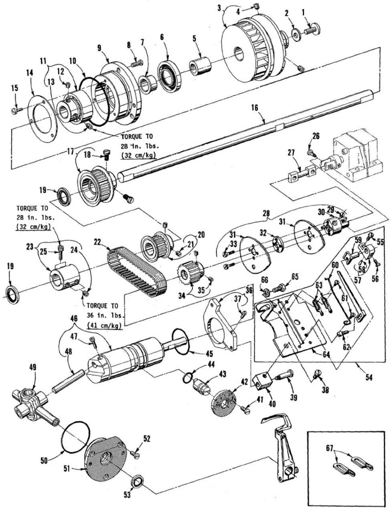
TORQUE TO 28 in. 1bs. (32 cm/kg) TORQUE TO 28 in. 1bs. (32 cm/kg) TORQUE TO 36 in. 1bs. (41 cm/kg)P166
LOWER MAINSHAFT AND LOOPER DRIVE
| Ref. No. | Part No. | Description | Amt. Req. |
| 1 | 141 | Screw | 1 |
| 2 | HA20 A | Washer | 1 |
| 3 | C50021 D | Pulley, for Styles XF511H100MF, MG, MAW, 112MF, 112MG and 151MF | 1 |
| - | C50021 F | Pulley, for all Styles except XF511H100MF, MG, MAW, 112MF, 112MG and 151MF | 1 |
| 4 | 22651 CD-4 | Screw, set | 2 |
| 5 | C50021 C | Spacer, pulley; for all Styles except XF511H100MF, MG, MAW, 112MF, 112MG and 151MF | 1 |
| 6 | 660-688 | Seal, mainshaft | 1 |
| 7 | C50090 B | Collar, spacer | 1 |
| 8 | 22569 B | Screw | 3 |
| 9 | C50090 | Housing, mainshaft bearing | 1 |
| 10 | 660-757 | "0" Ring | 1 |
| 11 | C50036 P | Bearing and Collar Assembly | 1 |
| 12 | 22894 AD | Screw, set | 1 |
| 13 | 22894 L | Screw, spot (required to replace screw in Ref. No. 11) | 1 |
| 14 | C50090 D | Plate, retaining | 1 |
| 15 | 22520 | Screw | 3 |
| 16 | C50022 A | Mainshaft, lower | 1 |
| 17 | C50042 H | Sprocket, lower mainshaft | 1 |
| 18 | 22839 A | Screw | 2 |
| 19 | 660-719 | Seal, oil | 2 |
| 20 | C50042 G | Sprocket, looper drive | 1 |
| 21 | 98 | Screw, set | 2 |
| 22 | C50042 AD | Belt, looper drive | 1 |
| 23 | C50043 | Coupling, lower mainshaft | 1 |
| 24 | 22894 AE | Screw, set | 2 |
| 25 | 22652 A-8 | Screw | 2 |
| 26 | 22731 | Screw | 2 |
| 27 | C50093 BC | Shaft, connecting | 1 |
| 28 | C50023 F | Take-Up Assembly, looper thread | 1 |
| 29 | 22580 D | Screw, set | 2 |
| 30 | C50023 E | Coupling | 1 |
| 31 | C50023 G | Disc, take-up | 2 |
| 32 | C50077 P | Spacer | 1 |
| 33 | 22797 B | Screw | 2 |
| 34 | C50042 F | Sprocket, looper driven | 1 |
| 35 | 88 | Screw, set | 2 |
| 36 | C50057 A | Bracket, collar | 1 |
| 37 | 22729 B | Screw | 1 |
| 38 | 22528 | Screw | 1 |
| 39 | 9846 A | Screw | 1 |
| 40 | C50057 C | Block, pivot | 1 |
| 41 | 22569 G | Screw | 2 |
| 42 | C50014 A | Plate, eccentric retaining | 1 |
| 43 | C50014 | Eccentric, looper avoid adjusting | 1 |
| 44 | 660-207 | "0" Ring | 1 |
| 45 | 660-443 | "0" Ring | 1 |
| 46 | 29105 AP | Looper Drive Assembly | 1 |
| 47 | 22653 J-8 | Screw | 1 |
| 48 | 667 J-33 | Crankpin | 1 |
| 49 | 29192 AE | Rocker Assembly, looper | 1 |
| 50 | 660-445 | "0" Ring | 1 |
| 51 | C50044 A | Housing, looper rocker bearing | 1 |
| 52 | 22569 G | Screw | 3 |
| 53 | C50044 V | Seal, oil | 1 |
| 54 | C50057 B | Cast-Off Support Plate Assembly | 1 |
| 55 | 22768 | Screw | 1 |
| 56 | 87 U | Screw | 1 |
| 57 | 52904 E | Bracket, retaining finger support | 1 |
| 58 | 50-216 BLK | Pin, dowel | 1 |
| 59 | 52804 E | Support, retaining finger | 1 |
| 60 | C50004 | Wire, cast-off | 1 |
| 61 | 73 A | Screw | 3 |
| 62 | 22516 | Screw | 1 |
| 63 | 52958 D | Eyelet | 2 |
| 64 | C50057 | Support, cast-off plate | 1 |
| 65 | 303 | Screw | 1 |
| 66 | 53634 C | Washer | 1 |
| 67 | 50358 H | Eyelet (two and three needle machines) | 2 |

text_image
TORQUE TO 36 in. 1bs. (41 cm/kg) TORQUE TO 24-26 in. 1bs. (28-30 cm/kg) TORQUE TO 36 in. 1bs. (41 cm/kg) TORQUE TO 36 in. 1bs. (41 cm/kg) TORQUE TO 24-26 in. 1bs. (28-30 cm/kg) TORQUE TO 24-26 in. 1bs. (28-30 cm/kg)FEED DRIVING PARTS
| Ref.No. | PartNo. | Description | Amt.Req. |
| 1 | 56335 D | Collar, thrust | 3 |
| 2 | 98 | Screw | 2 |
| 3 | C50035 K | Shaft, feed rocker | 1 |
| 4 | C067 D | Cork | 2 |
| 5 | C50035 F | Rocker, feed | 1 |
| 6 | C50035 A | Spacer | 2 |
| 7 | 22738 M | Screw | 2 |
| 8 | 660-683 | "0" Ring | 1 |
| 9 | 41391 | Washer | 1 |
| 10 | C50035 T | Shaft, stitch regulator | 1 |
| 11 | 56322 B | Gasket | 1 |
| 12 | 22891 D | Screw | 1 |
| 13 | C50035 AM | Link, stitch control | 1 |
| 14 | 22517 | Screw | 1 |
| 15 | 22516 A | Screw | 1 |
| 16 | C50036 | Pin, link | 1 |
| 17 | C50035 B | Link, feed drive (intermediate) | 1 |
| 18 | C50035 AR | Link, intermittent | 1 |
| 19 | 22516 B | Screw | 1 |
| 20 | C50034 D | Spacer, feed bar | 1 |
| 21 | 22570 A | Screw | 1 |
| 22 | C50034 X | Feed Bar | 1 |
| 23 | C50034 Z | Eccentric | 1 |
| 24 | 22517 | Screw | 2 |
| 25 | C50047 G | Counterweight | 1 |
| 26 | 95 | Screw, set | 1 |
| 27 | 96 A | Screw, spot | 1 |
| 28 | C50036 C | Pin, link | 1 |
| 29 | C50045 B | Link, connecting | 2 |
| 30 | 22845 R | Screw | 1 |
| 31 | 22839 G | Screw | 1 |
| 32 | C50036 M | Block, feed lift guide | 1 |
| 33 | C50036 F | Pin, feed lift adjusting | 1 |
| 34 | C50036 E | Bushing, feed lift adjusting | 1 |
| 35 | 22894 K | Screw | 1 |
| 36 | 660-677 | "0" Ring | 1 |
| 37 | 22519 M | Screw | 1 |
| 38 | HA20 A | Washer | 1 |
| 39 | C50036 D | Dial, feed lift adjusting | 1 |
| 40 | C50036 G | Link, intermittent (feed lift control) | 1 |
| 41 | 22516 B | Screw | 1 |
| 42 | C50043 H-025 | Washer, .025 inch (.635mm) thick | 1 |
| - | C50043 H-021 | Washer, .021 inch (.533mm) thick | 1 |
| - | C50043 H-029 | Washer, .029 inch (.737mm) thick | 1 |
| 43 | C50036 A | Link, feed lift | 1 |
| 44 | C50036 B | Pin, link | 1 |
| 45 | 22804 | Screw | 2 |
| 46 | C50034 N | Bracket, feed bar thrust | 1 |
| 47 | 187 A | Screw | 2 |
| 48 | C50034 L | Scraper, oil, feed bar (rear) | 1 |
| 49 | C50034 H | Guide, feed bar (left) | 1 |
| 50 | C50034 M | Guide, feed bar (right) | 1 |
| 51 | C50034 F | Holder, feed bar guide | 1 |
| 52 | C50034 K | Scraper, oil, feed bar (front) | 1 |
| 53 | C50034 AG | Seal, retainer | 2 |
| 54 | C50034 AK | Seal, oil, feed bar | 1 |
| 55 | C50034 G | Spring, oil seal | 1 |
| 56 | C50034 J | Plate, feed bar oil seal | 1 |
| 57 | 22594 | Screw | 4 |
| 58 | 22868 C | Screw | 2 |
| 59 | C50034 AH | Holder, feed dog | 1 |
| 60 | 22637 P-24 | Screw | 1 |
| 61 | C50034 V | Cam, feed dog tilting | 1 |
| 62 | 605 A | Screw | 1 |
| 63 | -- - | Feed Dog, See "SEWING COMBINATIONS" | 1 |
| 64 | 22519 H | Screw | 1 |
| 65 | C50022 G | Shaft, feed drive | 1 |
text_image
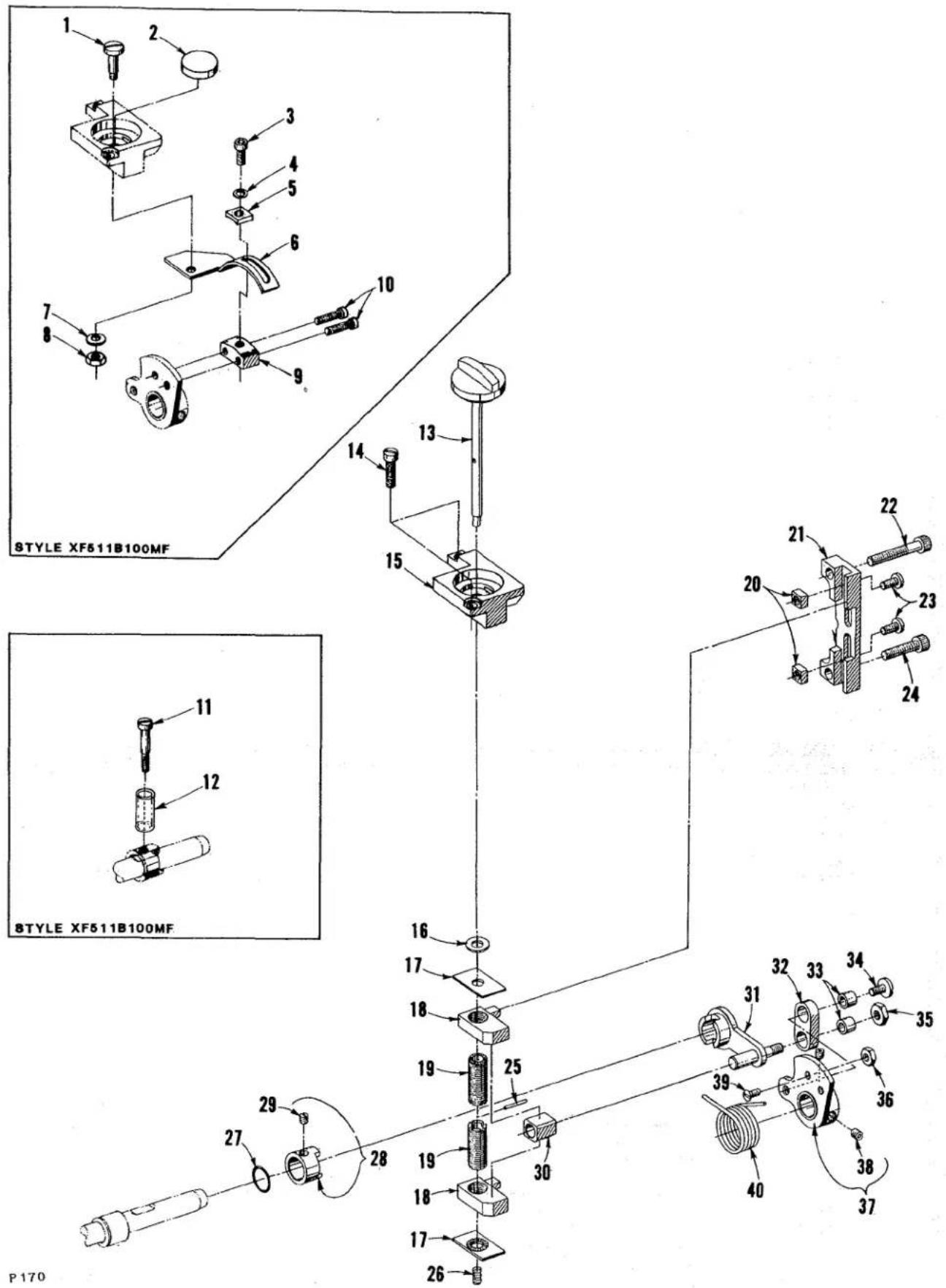
STYLE XF511B100MF STYLE XF511B100MF P 170STITCH REGULATING PARTS
| Ref.No. | PartNo. | Description | Amt.Req. |
| 1 | 22778 A | Screw | 1 |
| 2 | C50051 X | Plug, stitch adjustment hole | 1 |
| 3 | 22596 H | Screw | 1 |
| 4 | 53634 C | Washer | 1 |
| 5 | C50035 AS | Washer | 1 |
| 6 | C50035 AA | Bracket, mounting | 1 |
| 7 | 61434 G | Washer | 1 |
| 8 | 9937 | Nut | 1 |
| 9 | C50035 AB | Block, support | 1 |
| 10 | 22729 AA | Screw | 2 |
| 11 | 9846 | Screw (required to replace screw in Ref. No. 28) | 1 |
| 12 | C50093 CH | Cap, tube for screw 9846 approx. 1/2 inch (12.7mm) | 1 |
| 13 | C50035 AL | Shaft w/knob, stitch adjusting | 1 |
| 14 | 22541 A | Screw | 2 |
| 15 | C50035 AP | Bracket, stitch control support | 1 |
| 16 | 39198 D | Washer | 1 |
| 17 | C50035 R | Retainer, stitch length | 2 |
| 18 | C50035 V | Block, limit, stitch regulator | 2 |
| 19 | C50035 S | Screw, stitch regulating | 2 |
| 20 | C50035 H | Nut, stitch limiting | 2 |
| 21 | C50035 AN | Bracket, guide, stitch control | 1 |
| 22 | 22652 B-10 | Screw | 1 |
| 23 | 22570 A | Screw | 2 |
| 24 | 22652 B-12 | Screw | 1 |
| 25 | C50035 AJ | Pin, roll, for stitch adjusting shaft | 1 |
| 26 | 660-884 | Spring, stitch adjusting | 1 |
| 27 | 660-683 | "0" Ring for feed rocker shaft bushing (right) | 1 |
| 28 | C50035 | Collar, actuating | 1 |
| 29 | 88 B | Screw, set | 1 |
| 30 | C50035 P | Block, stitch regulating | 1 |
| 31 | C50035 W | Lever, stitch control | 1 |
| 32 | C50035 BC | Link, stitch regulating | 1 |
| 33 | C50037 A | Ferrule | 2 |
| 34 | 88 D | Screw | 1 |
| 35 | 14077 | Nut | 1 |
| 36 | 41071 G | Nut | 1 |
| 37 | C50035 X | Indicator, stitch | 1 |
| 38 | 22894 W | Screw | 2 |
| 39 | 87 | Screw | 1 |
| 40 | C50035 N | Spring | 1 |
text_image
Technical diagram of a mechanical assembly with numbered components for identification
text_image
Technical diagram of mechanical assembly with numbered components and labeled partsP169
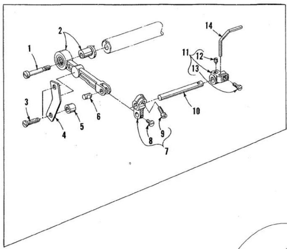
REAR NEEDLE GUARD AND PNEUMATIC STITCH SHORTENING
| Ref.No. | PartNo. | Description | Amt.Req. |
| 1 | 22758 K | Screw | 1 |
| 2 | C50068 U | Link Assembly, crank, rear needle guard | 1 |
| 3 | 22541 D | Screw | 2 |
| 4 | C50068 Y | Plate, retaining | 1 |
| 5 | C50068 Z | Spacer | 2 |
| 6 | C50068 C | Pin, pivoting | 1 |
| 7 | C50068 B | Link, pivot, rear needle guard | 1 |
| 8 | 98 A | Screw | 1 |
| 9 | 22729 L | Screw | 1 |
| 10 | C50068 A | Shaft, rear needle guard | 1 |
| 11 | C50025 A | Holder, needle guard; all Styles exceptXF512E100HB-1, MP-12, MP-16, XF513E100HJ-8, HJ-9,HR-9, 101HR-9 and 112HR-9 | 1 |
| - | C50025 F | Holder, needle guard; for Styles XF512E100HB-1,MP-12, MP-16, XF513E100HJ-8, HJ-9, HR-9, 101HR-9and 112HR-9 | 1 |
| 12 | 22764 | Screw, spot | 1 |
| 13 | 22562 A | Screw | 1 |
| 14 | --- | Needle Guard, See "SEWING COMBINATIONS" | 1 |
| 15 | 22652 A-6 | Screw | 2 |
| 16 | C50035 AW | Arm, connecting | 1 |
| 17 | C50035 AZ | Collar, adaptor | 1 |
| 18 | 22552 A-16 | Screw | 1 |
| 19 | C50035 AY | Adjuster, clevis | 1 |
| 20 | 21756 G | Screw, adjusting | 1 |
| 21 | 22743 | Screw | 1 |
| 22 | 89-64 | Plug, pressure | 1 |
| 23 | 22789 A | Screw, pivot | 1 |
| 24 | RM3211-1 | Nut, lock | 1 |
| 25 | C50035 BA | Bracket, mounting | 1 |
| 26 | 22640 R-40 | Bolt, mounting | 1 |
| 27 | 22758 E | Screw | 2 |
| 28 | C50035 AX | Bracket, hinge | 1 |
| 29 | 671 A-65 | Cylinder, air | 1 |
| 30 | 671 F-69 | Fitting, air | 1 |
| 31 | RM2997 D | Tubing, air; 1/4 inch (6.35mm) O.D. specifylength as req. | |
text_image
TORQUE TO 19-21 in. 1bs. (22-24 cm/kg) 19 18 17 16 15 14 13 12 11 10 9 8 7 6 5 4 3 2 19 27 26 25 24 23 22 21 20 13 30 31 32 33 34 35 36 37 38 39 40 41 42 43 44 45 46 47 48P171
PRESSER FOOT AND LIFTER LEVER PARTS
| Ref.No. | PartNo. | Description | Amt.Req. |
| 1 | C50056 D | Regulator, presser bar spring | 1 |
| 2 | C50056 B | Guide, presser bar spring | 1 |
| 3 | C50056 C | Spring, presser bar; for all Styles except XF512E100HB-1,XF513E100HJ-8, HJ-9, HR-9, 101HR-9 and 112HR-9 | 1 |
| - | C50056 L | Spring, presser bar; for Styles XF512E100HB-1,XF513E100HJ-8, HJ-9, HR-9, 101HR-9 and 112HR-9 | 1 |
| 4 | C50056 K | Guide, presser bar | 1 |
| 5 | 22840 C | Screw, adjusting | 1 |
| 6 | C50056 J | Nut, lock | 1 |
| 7 | 531 | Screw | 2 |
| 8 | C50067 K | Plate, presser bar guide | 1 |
| 9 | 22569 C | Screw | 2 |
| 10 | C50057 E | Bar, presser; for all Styles exceptXF513E100HJ-8, HJ-9, HR-9, 101HR-9, 112HR-9 | 1 |
| 11 | C50057 K | Bar, presser; for Styles XF513E100HJ-8, HJ-9,HR-9, 101HR-9 and 112HR-9 | 1 |
| 12 | --- | Presser Foot Assembly, See "SEWING COMBINATIONS" | 1 |
| 13 | 22758 | Screw | 5 |
| 14 | 660-718 | Washer, spring | 3 |
| 15 | C50067 F | Link, presser foot lift | 1 |
| 16 | C50067 G | Lever, presser foot lift (upper left) | 1 |
| 17 | 22596 H | Screw | 1 |
| 18 | 51854 C | Washer | 1 |
| 19 | C50022 C | Shaft, presser foot lift (upper) for all Stylesexcept XF511E101MF, 118MF, 152MF and XF513E101HR-9 | 1 |
| - | C50076 C | Shaft, presser foot lift (upper) for StylesXF511E101MF, 118MF, 152MF and XF513E101HR-9 | 1 |
| 20 | C50090 N | Spring, tension release return | 1 |
| 21 | C50090 M | Collar, tension release adjusting | 1 |
| 22 | 22894 P | Screw | 2 |
| 23 | C50090 J | Sleeve, tension release; for all Styles exceptXF512E100HB-1, MP-12, MP-16, XF513E100HJ-8, HJ-9, HR-9,101HR-9 and 112HR-9 | 1 |
| - | C50090 J | Sleeve, tension release; for Styles XF512E100HB-1, MP-12,MP-16, XF513E100HJ-8, HJ-9, HR-9, 101HR-9 and 112HR-9 | 2 |
| 24 | 22894 W | Screw, for all Styles except XF512E100HB-1, MP-12,MP-16, XF513E100HJ-8, HJ-9, HR-9, 101HR-9 and 112HR-9 | 2 |
| - | 22894 W | Screw, for Styles XF512E100HB-1, MP-12, MP-16,XF513E100HJ-8, HJ-9, HR-9, 101HR-9 and 112HR-9 | 4 |
| 25 | C50067 B | Lever, presser foot lifter (upper right) | 1 |
| 26 | 22519 K | Screw | 1 |
| 27 | C50067 | Connection, presser foot lift | 1 |
| 28 | C50067 D | Lever, presser foot lift (lower) | 1 |
| 29 | 22882 | Screw | 2 |
| 30 | C50067 A | Lever, presser foot lift (outer) | 1 |
| 31 | 627 A | Screw | 1 |
| 32 | 15037 A | Nut, locking | 1 |
| 33 | 22894 C | Screw | 2 |
| 34 | 667 M-14 | Pin, dowel (lifter lever stop) | 1 |
| 35 | C50022 D | Shaft, presser foot lift (lower) | 1 |
| 36 | C50036 R | Collar, thrust | 1 |
| 37 | 22894 L | Screw, spot | 1 |
| 38 | C50077 E | Lever, lifter | 1 |
| 39 | 93 | Screw | 1 |
| 40 | C50077 F | Link, connecting | 1 |
| 41 | C50077 AD | Spacer, for C50077 G | 1 |
| 42 | C50077 G | Lever, lifter (roller) | 1 |
| 43 | 22557 J | Screw, shoulder | 1 |

text_image
Exploded view diagram of a UnionSpecal industrial machine (UNI/XF-500) with numbered components and exploded views.FRONT COVER AND THREAD HANDLING PARTS
| Ref.No. | PartNo. | Description | Amt.Req. |
| 1 | 50378 R | Wire, thread separating; for two and three needle machines | 1 |
| 2 | C50058 F | Wire, rubbing (needle thread) | 1 |
| 3 | 50370 | Cam, needle thread; for single needle machines | 1 |
| 3A | 50358 J | Cam, needle thread take-up; for StylesXF512E100HB-1, MP-12 and MP-16 | 1 |
| 3B | C50070 B | Cam, needle thread take-up; for StylesXF513E100HJ-8, HJ-9, HR-9, 101HR-9 and 112HR-9 | 1 |
| 4 | 22569 C | Screw | 3 |
| 5 | 50370 A | Wire, strike-off (needle thread) | 1 |
| 6 | C50054 M | Guard, needle bar eyelet | 1 |
| 7 | 531 | Screw | 1 |
| 8 | 22569 C | Screw | 2 |
| 9 | 29476 PX | Thread Control Assembly, for all Styles exceptXF512E100HB-1, MP-12 and MP-16 | 1 |
| - | 29476 PY | Thread Control Assembly, for Styles XF512E100HB-1,MP-12 and MP-16 | 1 |
| 10 | 98 A | Screw | 1 |
| - | 22726 L | Screw for 50358 K | 1 |
| 11 | 158 A | Eyelet, adjustable | 1 |
| 11A | 50358 K | Eyelet, adjustable; for 29476 PY | 1 |
| 12 | 22837 | Screw | 1 |
| 13 | 56358 C | Washer, guide | 1 |
| 14 | 56358 D | Spacer | 1 |
| 15 | 56358 B | Block, guide | 1 |
| 16 | 50304 D | Plate, needle thread control | 1 |
| 17 | 57 WD | Screw | 1, 2 or 3 |
| 18 | 57 WC | Spring | 1, 2 or 3 |
| 19 | 57 WB | Plate, needle thread nipper | 1, 2 or 3 |
| 20 | 63471 | Base, needle thread nipper | 1, 2 or 3 |
| 21 | 18-1077 | Screw, for 63471 | 1, 2 or 3 |
| 22 | 109 | Disc, tension | 4, 8 or 12 |
| 23 | 56392 F | Shield, tension spring | 2, 4 or 6 |
| 24 | C50092 M | Washer, tension release | 1, 2 or 3 |
| 25 | 51292 F-8 | Spring, needle thread tension | 1, 2 or 3 |
| 26 | 39592 AK | Ferrule, tension spring | 2, 4 or 6 |
| 27 | C50092 S | Nut, thread tension | 2, 4 or 6 |
| 28 | C50092 L | Post, tension (needle thread) | 1, 2 or 3 |
| 29 | C50092 J | Pin, thread tension release | 1, 2 or 3 |
| 30 | 51292 A | Ferrule, tension post | 2 or 3 |
| 31 | C50092 R | Washer | 1, 2 or 3 |
| 32 | 50392 B | Housing, tension assembly | 1, 2 or 3 |
| 33 | C50092 G | Pin, tension release actuating | 1, 2 or 3 |
| 34 | 18-799 | Screw | 1, 2 or 3 |
| 35 | 51292 F-2 | Spring, looper thread tension | 1, 2 or 3 |
| 36 | 56392 E | Post, tension (looper thread) | 1, 2 or 3 |
| 37 | 22501 A | Screw | 4 |
| 38 thru 70 | See Following Page | ||
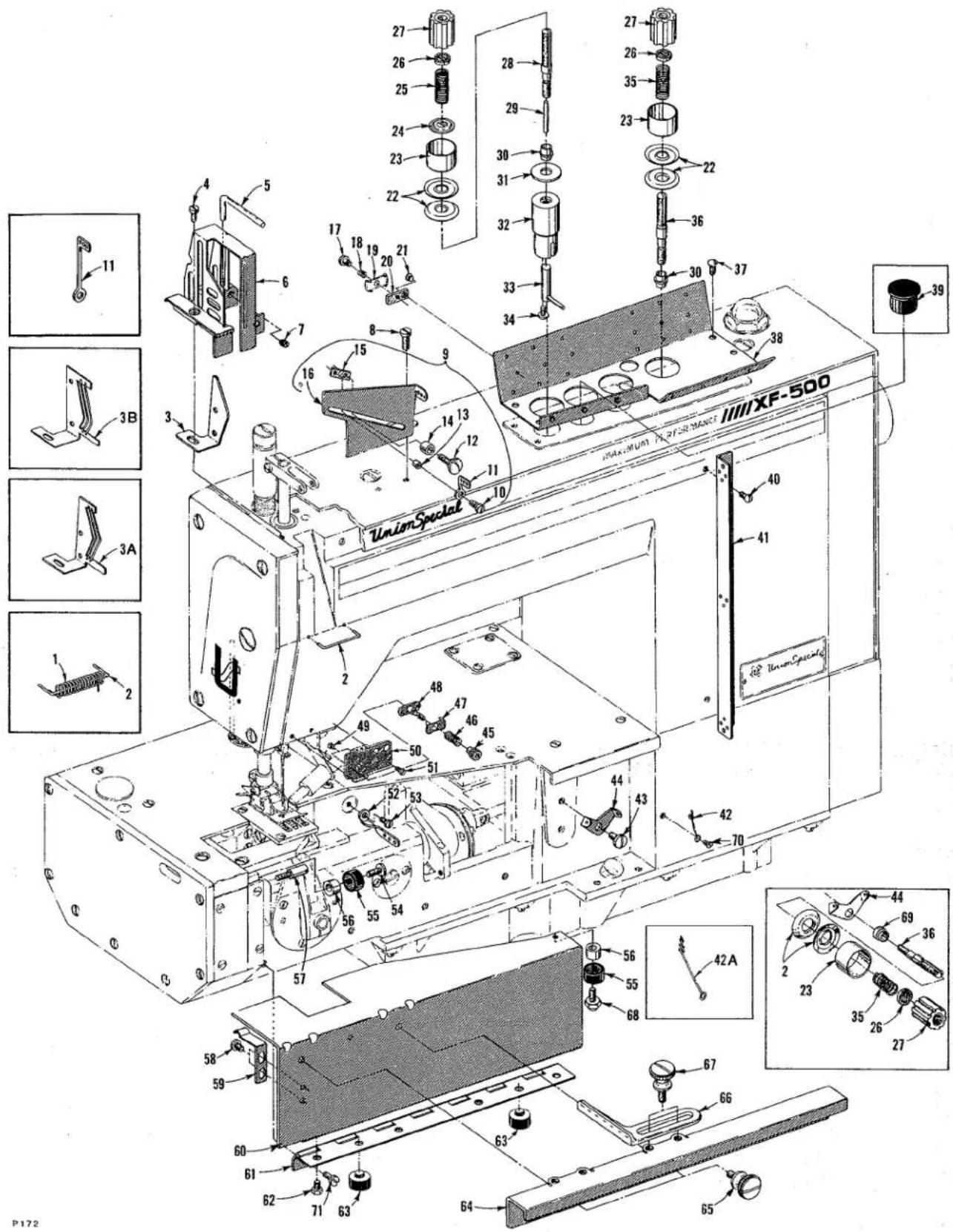
text_image
Exploded view diagram of a Union Special air conditioner unit with numbered components and exploded viewsFRONT COVER AND THREAD HANDLING PARTS
| Ref.No. | PartNo. | Description | Amt.Req. |
| 1 thru 37 | See Preceding Page | ||
| 38 | C50092 N | Guide, thread | 1 |
| 39 | C50082 AH | Plug, top cover; for Styles XF512E100HB-1, MP-12 and MP-16 | 1 |
| 40 | 22635 G-16 | Screw | 2 |
| 41 | C50058 A | Eyelet, looper thread | 1 |
| 42 | 39868 H | Eyelet, looper thread; for all Styles except XF512E100HB-1, MP-12, MP-16, XF513E100HJ-8, HJ-9, HR-9, 101HR-9 and 112HR-9 | 1 |
| 42A | 52958 G | Eyelet, looper thread; for Styles XF512E100HB-1, MP-12, MP-16, XF513E100HJ-8, HJ-9, HR-9, 101HR-9 and 112HR-9 | 1 |
| 43 | 22872 | Screw, for all Styles except XF512E100HB-1, MP-12, MP-16, XF513E100HJ-8, HJ-9, HR-9, 101HR-9 and 112HR-9 | 1 |
| 44 | 51292 D | Eyelet, looper thread | 1, 2 or 3 |
| 45 | 51959 D | Nut | 1 |
| 46 | 15438 C | Spring | 1 |
| 47 | 57 WB | Plate, spring | 1 |
| 48 | C50092 U | Post, nipper base | 1 |
| 49 | 22716 A | Screw | 2 |
| 50 | C50044 T | Plate, mounting thread guide | 1 |
| 51 | 605 A | Screw | 2 |
| 52 | 56958 | Eyelet, looper thread | 1 |
| 53 | 22520 | Screw | 1 |
| 54 | 22569 J | Screw | 1 |
| 55 | C50093 BR | Bumper, rubber | 2 |
| 56 | C50082 W | Stop, adjustable | 2 |
| 57 | 22799 AH | Stud, latch spring | 1 |
| 58 | 22513 | Screw | 2 |
| 59 | C50032 | Spring, latch | 1 |
| 60 | C50082 Y | Cover, front; for all Styles except XF512E100HB-1, MP-12, MP-16, XF513E100HJ-8, HJ-9, HR-9, 101HR-9 and 112HR-9 | 1 |
| - | C50082 Z | Cover, front; for Styles XF512E100HB-1, MP-12, MP-16, XF513E100HJ-8, HJ-9, HR-9, 101HR-9 and 112HR-9 | 1 |
| 61 | C50078 C | Hinge, front | 1 |
| 62 | 22792 A | Screw | 4 |
| 63 | 660-731 | Bumper, rubber | 2 |
| 64 | C50001 D | Extension, cloth plate | 1 |
| 65 | 25 E | Screw | 2 |
| 66 | 24 | Guide, edge; for all Styles except XF512E100HB-1, MP-12, MP-16, XF513E100HJ-8, HJ-9, HR-9, 101HR-9 and 112HR-9 | 1 |
| 67 | 25 | Screw, for all Styles except XF512E100HB-1, MP-12, MP-16, XF513E100HJ-8, HJ-9, HR-9, 101HR-9 and 112HR-9 | 2 |
| 68 | C50032 C | Screw, cover latch | 1 |
| 69 | 51192 B | Ferrule, tension post; for Styles XF512E100HB-1, MP-12, MP-16, XF513E100HJ-8, HJ-9, HR-9, 101HR-9 and 112HR-9 | 2 or 3 |
| 70 | 22585 A | Screw | 1 |
| 71 | 22569 D | Screw | 4 |
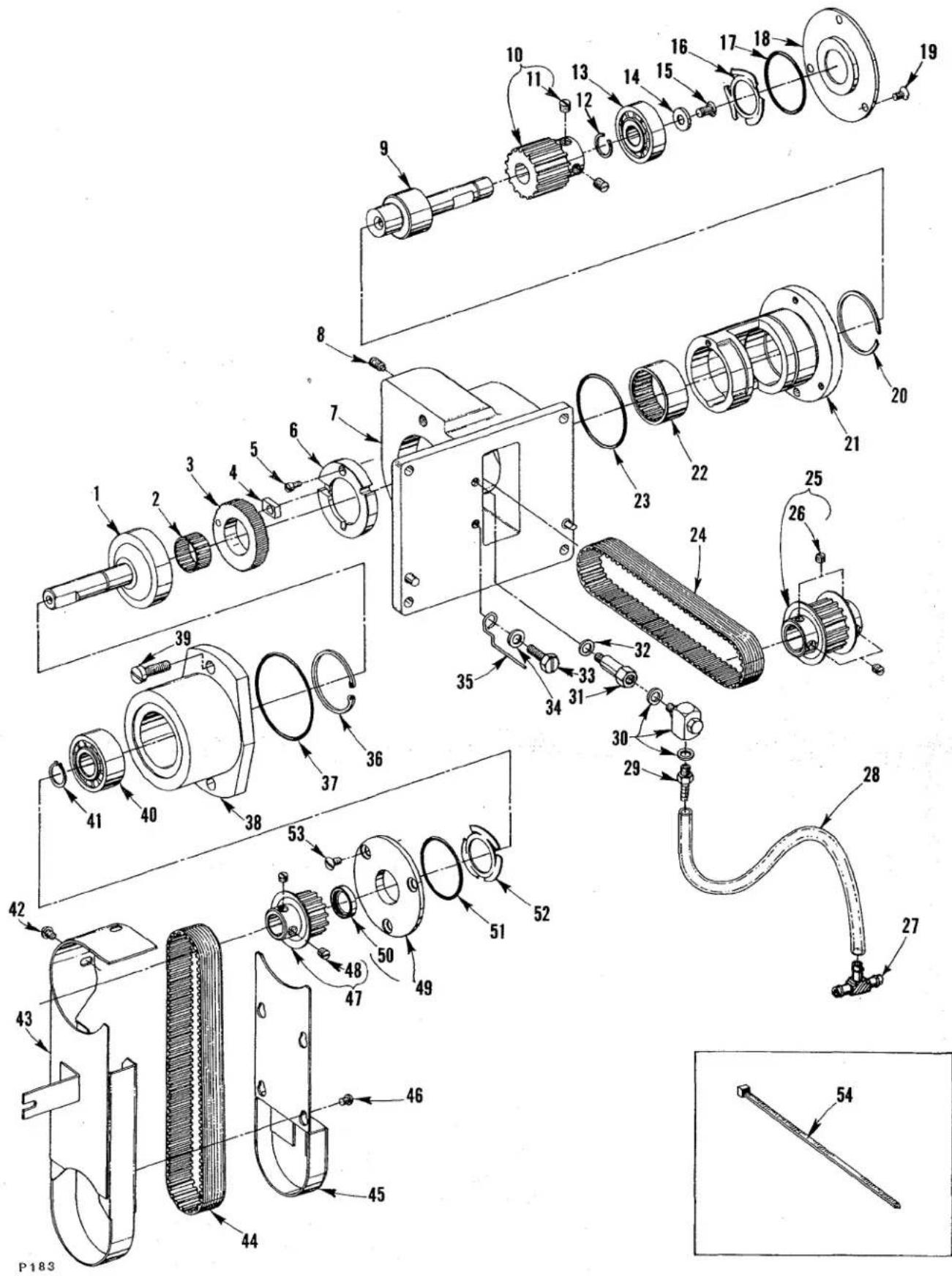
text_image
Exploded view diagram of a mechanical assembly with numbered parts for identificationPULLER DRIVE
| Ref.No. | PartNo. | Description | Amt.Req. |
| 1 | C50078 L | Gear, internal | 1 |
| 2 | 660-889 | Bearing, cage | 1 |
| 3 | C50078 M | Gear | 1 |
| 4 | C50078 J | Block, slide | 1 |
| 5 | 22593 | Screw | 1 |
| 6 | C50078 N | Ring, guide | 1 |
| 7 | C50078 G | Housing, bearing | 1 |
| 8 | 22894 J | Screw | 1 |
| 9 | C50022 L | Shaft, eccentric drive | 1 |
| 10 | C50042 AC-16 | Sprocket | 1 |
| 11 | 98 | Screw | 2 |
| 12 | 660-891 C | Ring, retaining | 1 |
| 13 | 660-888 | Bearing, ball | 1 |
| 14 | 59451 F | Washer | 1 |
| 15 | 22574 D | Screw (left hand threads) | 1 |
| 16 | 660-914 | Spring, finger | 1 |
| 17 | 660-886 A | "0" Ring | 1 |
| 18 | C50082 AR | Cover | 1 |
| 19 | 22524 | Screw | 3 |
| 20 | 661-70 A | Ring, snap | 1 |
| 21 | C50078 P | Housing, eccentric | 1 |
| 22 | 660-892 C | Bearing | 1 |
| 23 | 660-886 C | "0" Ring | 1 |
| 24 | C50042 AF | Belt, timing | 1 |
| 25 | C50042 AB-16 | Sprocket | 1 |
| 26 | 98 | Screw | 4 |
| 27 | 671 F-41 | Tee, union | 1 |
| 28 | C50094 AF | Tube, oil | 1 |
| 29 | 671 F-19 | Connector | 1 |
| 30 | RM3633-1 | Fitting, oil | 1 |
| 31 | 671 F-64 | Fitting, extension | 1 |
| 32 | RM2964 B | Washer | 1 |
| 33 | 22824 B | Screw | 1 |
| 34 | 53634 C | Washer | 1 |
| 35 | C50093 CS | Protector, tube | 1 |
| 36 | 660-891 B | Ring, snap | 1 |
| 37 | 660-886 B | "0" Ring | 1 |
| 38 | C50078 H | Housing, bearing | 1 |
| 39 | 136 | Screw | 2 |
| 40 | 660-890 | Bearing, ball | 1 |
| 41 | 660-918 | Ring, retaining | 1 |
| 42 | 22825 | Screw | 3 |
| 43 | 21375 BX | Guard, belt | 1 |
| 44 | C50042 AG | Belt, drive | 1 |
| 45 | 21375 BY | Cover | 1 |
| 46 | 604 | Screw | 4 |
| 47 | C50042 Z-13 | Sprocket, puller driving (See sprocket chart for stitch length combinations) | 1 |
| 48 | 22560 B | Screw | 2 |
| 49 | C50082 AP | Cover | 1 |
| 50 | 660-893 | Seal, lip | 1 |
| 51 | 660-886 A | "0" Ring | 1 |
| 52 | 660-914 | Spring, finger | 1 |
| 53 | 22524 | Screw | 3 |
| 54 | 670 E-2 | Tie, cable; to secure Ref. No. 28 | 1 |
NOTE: Ref. No. 1-24, 36-41 and 49-53 can be ordered under Assembly No. 29476 PK.
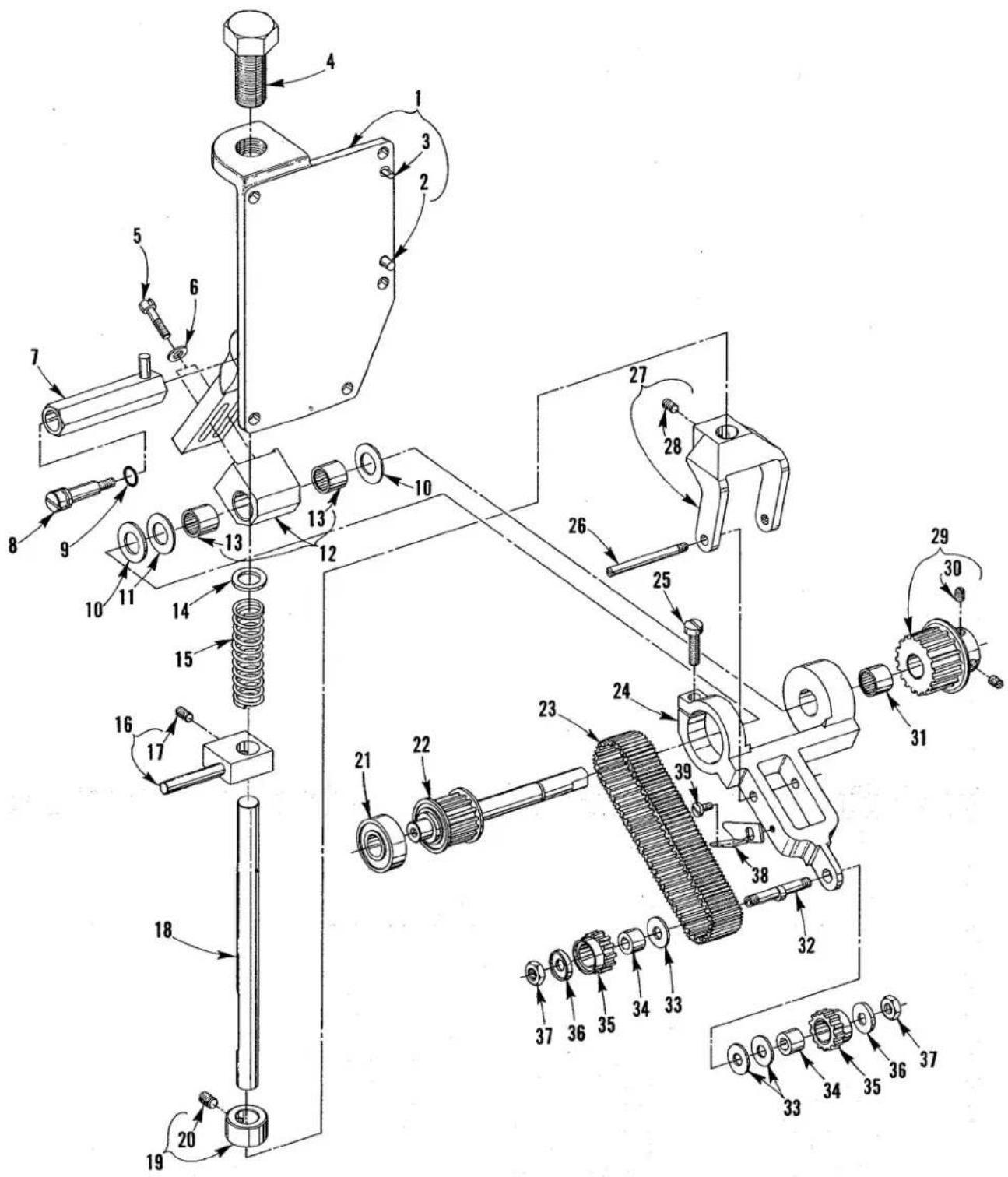
text_image
Technical diagram of a mechanical assembly with numbered components and exploded viewP185
BELT PULLER
| Ref.No. | PartNo. | Description | Amt.Req. |
| 1 | C50078 AE | Bracket, mounting | 1 |
| 2 | 667 C-8 | Pin, dowel | 1 |
| 3 | 51-716 BLK | Pin, locating | 1 |
| 4 | C50077 D | Screw, adjusting | 1 |
| 5 | 88 F | Screw | 2 |
| 6 | 8372 A | Washer | 2 |
| 7 | C50077 C | Sleeve, stop | 1 |
| 8 | C50077 B | Stud, screw | 1 |
| 9 | 660-220 | "O" Ring | 1 |
| 10 | C50077 M | Washer | 2 |
| 11 | C50077 J | Washer | 1 |
| 12 | C50078 AC | Plate, binder | 1 |
| 13 | 660-892 A | Bearing, needle | 2 |
| 14 | 51242 L | Washer | 1 |
| 15 | 28633 L | Spring | 1 |
| 16 | C50077 H | Collar, lifting | 1 |
| 17 | 22894 AM | Screw | 1 |
| 18 | C50078 Y | Rod, lifter | 1 |
| 19 | C50036 R | Collar, stop | 1 |
| 20 | 98 | Screw, set (required to replace screw in Ref. No. 19) | 1 |
| 21 | 660-887 | Bearing, ball | 1 |
| 22 | C50078 AB | Shaft, drive | 1 |
| 23 | C50042 AK | Belt, material puller | 1 |
| 24 | C50078 W | Yoke, roller | 1 |
| 25 | 136 | Screw | 1 |
| 26 | 22570 E | Screw | 1 |
| 27 | C50078 AA | Lifter | 1 |
| 28 | 22894 R | Screw | 1 |
| 29 | C50042 Z-16 | Sprocket, puller driven (see sprocket chart for stitch length combinations) | 1 |
| 30 | 22560 B | Screw | 2 |
| 31 | 660-892 B | Bearing | 1 |
| 32 | C50078 X | Shaft, eccentric | 1 |
| 33 | C50077 N | Washer | 3 |
| 34 | C50037 D | Ferrule | 2 |
| 35 | C50042 AJ-12 | Sprocket | 2 |
| 36 | C50063 Y | Washer | 2 |
| 37 | 18 | Nut | 2 |
| 38 | 52930 AC | Knife, chain cutting | 1 |
| 39 | 604 | Screw | 1 |
Ref No. 1 thru 39 can be ordered under Assembly No. 29476 PL.

text_image
Technical diagram of a mechanical assembly with numbered components and directional arrows indicating assembly steps.ROLLER PULLER
| Ref. No. | Part No. | Description | Amt. Req. |
| 1 | C50078 F | Bracket, mounting | 1 |
| 2 | 667 C-8 | Pin, dowel | 1 |
| 3 | 51-716 BLK | Pin, locating | 1 |
| 4 | C50077 D | Screw, adjusting | 1 |
| 5 | 88 F | Screw | 2 |
| 6 | 8372 A | Washer | 2 |
| 7 | C50077 C | Sleeve, stop | 1 |
| 8 | C50077 B | Stud, screw | 1 |
| 9 | 660-220 | "0" Ring | 1 |
| 10 | C50077 J | Washer | 2 |
| 11 | C50078 S | Block, mounting | 1 |
| 12 | 660-892 A | Bearing, needle | 2 |
| 13 | 94 | Screw | 4 |
| 14 | C50078 V | Guard, feed roller | 1 |
| 15 | 94 | Screw | 2 |
| 16 | 21375 BW | Guard, belt | 1 |
| 17 | C50042 Z-18 | Sprocket, puller driven (see sprocket chart for stitch length combinations) | 1 |
| 18 | 22560 B | Screw | 2 |
| 19 | 660-887 | Bearing, ball | 1 |
| 20 | C50042 AE | Belt, timing | 1 |
| 21 | C50022 K | Shaft, drive | 1 |
| 22 | C50078 E | Yoke, feed roller | 1 |
| 23 | 22894 E | Screw | 2 |
| 24 | 136 | Screw | 1 |
| 25 | 660-892 B | Bearing, needle | 1 |
| 26 | 51242 L | Washer | 1 |
| 27 | 28633 L | Spring | 1 |
| 28 | C50077 H | Collar, puller lifting | 1 |
| 29 | 22894 AM | Screw | 1 |
| 30 | C50078 T | Block, thrust | 1 |
| 31 | 39656 A | Knife, chain cutting | 1 |
| 32 | 604 | Screw | 1 |
| 33 | C50077 K | Washer | 2 |
| 34 | C50022 N | Shaft, upper roller | 1 |
| 35 | C50042 AL | Sprocket, drive | 1 |
| 36 | 660-892 A | Bearing, needle | 2 |
| 37 | 660-219 L | Pin, roll | 1 |
| 38 | C50075 B | Roller, upper (Smooth Polyurethane) | 1 |
| 39 | C50077 | Shaft, puller lifter | 1 |
| 40 | 660-416 | Ring, retaining | 2 |
| 41 | C50036 AJ | Pin, roller lifter | 1 |
| 42 | C50036 R | Collar, stop | 1 |
| 43 | 98 | Screw, set (required to replace screw in Ref. No. 42) | 1 |
Ref. Nos. 1 thru 43 to be ordered under Assembly No. 29476 PH with Smooth Polyurethane Roller and 29476 PW with Bakelite Saw Tooth Roller.
| 44 | AS22 D | Screw | 1 |
| 45 | C50078 R | Plate, feed | 1 |
| 46 | 22526 | Screw | 4 |
| 47 | C50078 U | Block, bearing | 2 |
| 48 | 22894 W | Screw | 2 |
| 49 | C50074 | Shaft | 1 |
| 50 | 660-330 | Ring, retaining | 2 |
| 51 | 6042 A | Washer | 3 |
| 52 | C50076 | Roller, lower (Smooth Polyurethane) | 1 |
| - | 50375 C | Roller, lower (Steel Diamond Knurled) | 1 |
| - | 50375 D | Roller, lower (Bakelite Saw Tooth) | 1 |
| 53 | C50078 AF-15 | Shim | as req. |
| - | C50078 AF-10 | Shim | as req. |
Ref Nos. 44 thru 52 can be ordered under Assembly No. 29476 PJ with Smooth Polyurethane Roller and 29476 PV with Bakelite Saw Tooth Roller.
| - | 50375 A | Roller, upper (Steel Diamond Knurled) | 1 |
| - | 50375 B | Roller, upper (Bakelite Saw Tooth) | 1 |
| - | 50375 | Roller, upper (Steel Saw Tooth) | 1 |
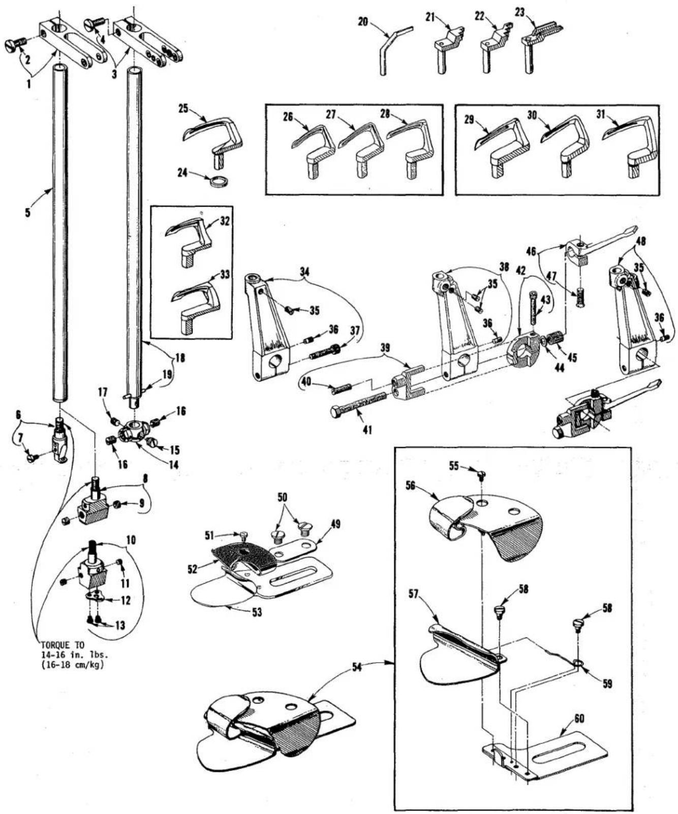
text_image
TORQUE TO 14-16 in. 1bs. (16-18 cm/kg) 5 2 3 4 25 24 20 21 22 23 26 27 28 29 30 31 32 33 34 35 36 37 38 39 40 41 42 43 44 45 46 47 48 50 51 52 53 54 55 56 57 58 59 60SEWING COMBINATIONS
| Ref.No. | PartNo. | Description | Amt.Req. |
| 1 | C50058 H | Eyelet, needle bar; for single needle machines | 1 |
| 2 | 18-71 | Screw | 1 |
| 3 | C50058 K | Eyelet, needle bar; for two and three needle machines | 1 |
| 4 | 18-71 | Screw | 1 |
| 5 | C50017 C | Bar, needle; for single and two needle machines | 1 |
| 6 | C50018 D | Head, needle; for single needle machines | 1 |
| 7 | 22768 A | Screw | 1 |
| 8 | C50018 L-12 | Head, needle; for Style XF512E100MP-12 | 1 |
| - | C50018 L-16 | Head, needle; for Style XF512E100MP-16 | 1 |
| 9 | 88 B | Screw | 2 |
| 10 | 50318 C | Head, needle; for Style XF512E100HB-1 | 1 |
| 11 | 22743 | Screw, needle | 2 |
| 12 | 50358 G | Guide, thread | 1 |
| 13 | 73 A | Screw | 2 |
| 14 | 35818 N-8 | Head, needle; for Style XF513E100HJ-8 | 1 |
| - | C50018 B-9 | Head, needle; for Styles XF513E100HJ-9, HR-9, 101HR-9, and 112HR-9 | 1 |
| 15 | 22752 | Screw, for center needle | 1 |
| 16 | 22580 | Screw, needle | 2 |
| 17 | 89 | Screw, spot | 1 |
| 18 | C50017 A | Bar, needle; for three needle machines | 1 |
| 19 | 50 J-26 | Pin, stop | 1 |
| 20 | C50025 | Guard, needle; for single needle machines | 1 |
| 21 | C50025 N | Guard, needle; for Styles XF512E100MP-12 and MP-16 | 1 |
| 22 | C50025 E | Guard, needle; for three needle machines | 1 |
| 23 | 50325 K | Guard, needle; for Style XF512E100HB-1 | 1 |
| 24 | 21210 | Collar, looper | 1 |
| 25 | 50390 D | Looper, for single needle machines | 1 |
| 26 | 51408-12 | Looper, front; for Style XF512E100MP-12 | 1 |
| 27 | 51408-16 | Looper, front; for Style XF512E100MP-16 | 1 |
| 28 | 51409 | Looper, back; for Styles XF512E100MP-12 and MP-16 | 1 |
| 29 | 51908 B-9 | Looper, front; for Styles XF513E100HJ-9, HR-9, 101HR-9 and 112HR-9 | 1 |
| - | 51908 B-8 | Looper, front; for Style XF513E100HJ-8 | 1 |
| 30 | 51909 C | Looper, middle; for all three needle machines | 1 |
| 31 | 51909 D-9 | Looper, back; for Styles XF513E100HJ-9, HR-9, 101HR-9 and 112HR-9 | 1 |
| - | 51909 D-8 | Looper, back; for Style XF513E100HJ-8 | 1 |
| 32 | 51509 C | Looper, back; for Style XF512E100HB-1 | 1 |
| 33 | 51508 G-1 | Looper, front; for Style XF512E100HB-1 | 1 |
| 34 | C50013 | Holder, looper; for single needle machines | 1 |
| 35 | 22565 X | Screw, set | 1, 2 or 3 |
| 36 | 22785 | Screw, adjusting | 1 |
| 37 | 22562 B-10 | Screw, binder | 1 |
| 38 | C50013 A | Holder, looper; for Styles XF512E100MP-12 and MP-16 | 1 |
| - | C50013 D | Holder, looper; for Style XF512E100HB-1 | 1 |
| 39 | C50041 G | Stop, for two and three needle machines | 1 |
| 40 | C50041 F | Spring, plunger | 1 |
| 41 | 22881 C | Screw, for C50041 G (two and three needle machines) | 1 |
| 42 | C50041 H | Collar, stop; for two and three needle machines | 1 |
| 43 | 22652 J-10 | Screw | 1 |
| 44 | 53634 C | Washer, looper carrier; for two and three needle machines | 1 |
| 45 | C50041 E | Lock, looper carrier; for two and three needle machines | 1 |
| 46 | C50041 D | Lever, release; for two and three needle machines | 1 |
| 47 | 538 A | Screw | 1 |
| 48 | C50013 B | Holder, looper; for three needle machines | 1 |
| 49 | 23425 V | Plate, washer | 1 |
| 50 | 25 C | Screw | 2 |
| 51 | 28 | Screw | 1 |
| 52 | 23421 U-12-1/16 | Scroll, upper for Style XF512E100MP-12 | 1 |
| - | 23421 U-16-1/16 | Scroll, upper for Style XF512E100MP-16 | 1 |
| - | 23421 U-16-3/32 | Scroll, upper for Style XF513E100HJ-8 | 1 |
| - | 23421 U-18-3/32 | Scroll, upper for Style XF513E100HJ-9 | 1 |
| 53 | 23422 U-1/16 | Lower Scroll and Base for Styles XF512E100MP-12 and MP-16 | 1 |
| - | 23422 BZ-3/32 | Lower Scroll and Base for Styles XF513E100HJ-8 and HJ-9 | 1 |
| 54 | 23420 S-9-1/8 | Folder Assembly for Styles XF513E100HR-9, 101HR-9 and 112HR-9 | 1 |
| 55 | 28 | Screw | 1 |
| 56 | 23421 S-9-1/8 | Scroll, upper | 1 |
| 57 | 23422 AY-18-1/8 | Scroll, lower | 1 |
| 58 | 22760 A | Screw | 2 |
| 59 | 23424 S | Spring | 1 |
| 60 | 23423 S | Base | 1 |

text_image
Technical diagram of a mechanical assembly with numbered parts, likely from an engineering manual or patenting context.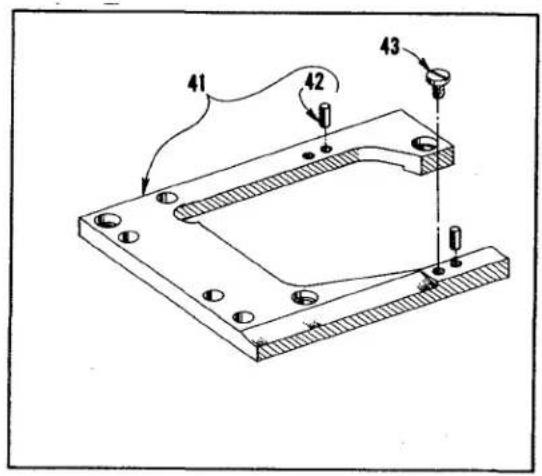
text_image
41 42 43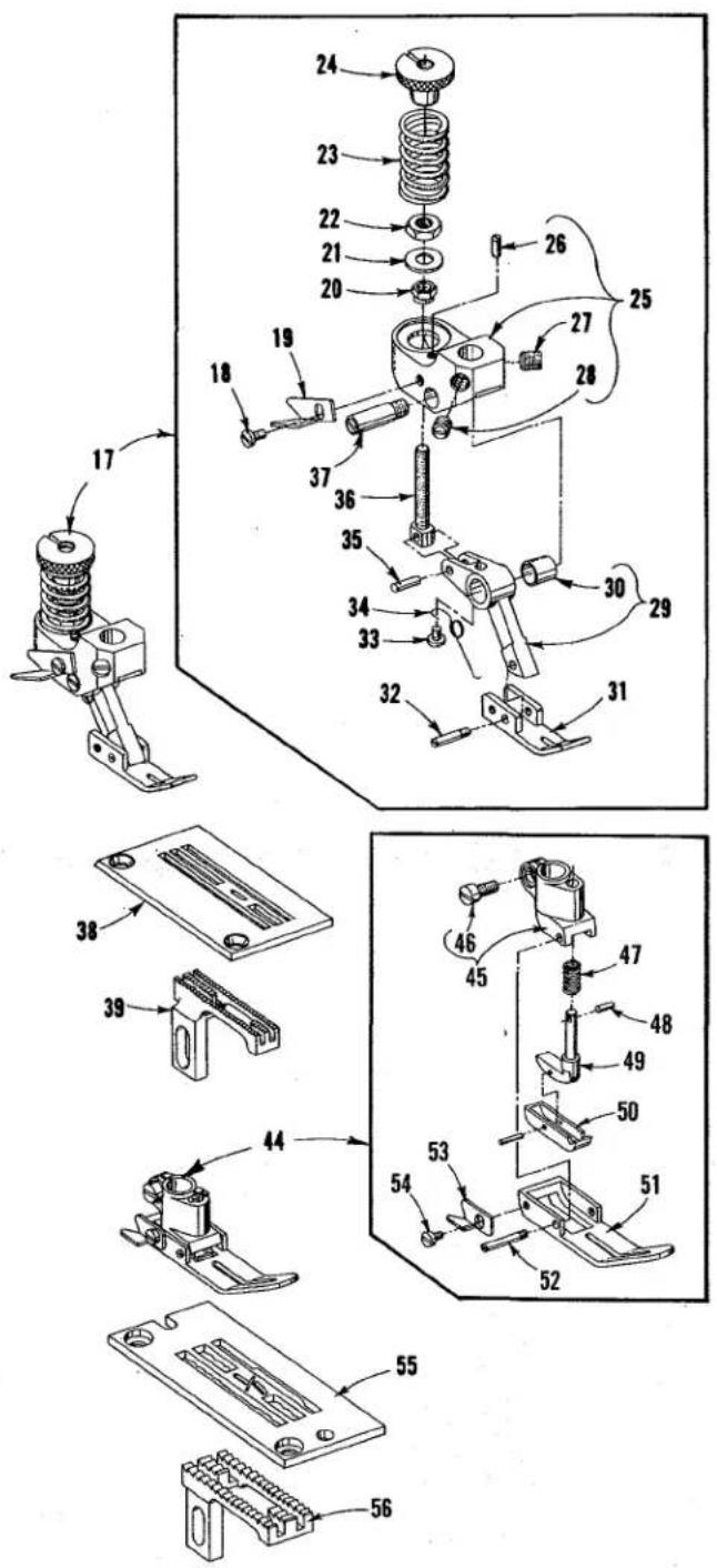
text_image
Technical diagram of a mechanical assembly with numbered parts, likely an electrical or mechanical component.SEWING COMBINATIONS
| Ref.No. | PartNo. | Description | Amt.Req. |
| 1 | C50020 | Presser Foot Assembly, for Styles XF511B100MF, XF511E101MF, 118MF, 152MF, XF511H100MF, 112MF, 100MG, 112MG and 151MF | 1 |
| 2 | 604 | Screw | 1 |
| 3 | 52930 AC | Knife, chain cutter | 1 |
| 4 | 22562 | Screw | 1 |
| 5 | C50030 | Shank, presser foot | 1 |
| 6 | 22784 M | Screw | 2 |
| 7 | C50031 | Guard, finger | 1 |
| 8 | C50030 A | Bottom, presser foot | 1 |
| 9 | C50030 D | Spring | 2 |
| 10 | C50030 B | Section, yielding | 1 |
| 11 | C50030 C | Spring | 2 |
| 12 | 22799 B | Screw, hinge | 1 |
| 13 | 50324 | Throat Plate, for Styles XF511B100MF, XF511E101MF, 118MF and XF511H100MF | 1 |
| - | C50024 B | Throat Plate, for Styles XF511E152MF, XF511H112MF and 151MF | 1 |
| 14 | C50005 F | Feed Dog, for Styles XF511B100MF, XF511E101MF, 118MF, 152MF, XF511H100MF, 112MF and 152MF | 1 |
| 15 | C50024 D | Throat Plate, for Style XF511H100MG | 1 |
| - | C50024 E | Throat Plate, for Style XF511H112MG | 1 |
| 16 | C50005 G | Feed Dog, for Styles XF511H100MG and 112MG | 1 |
| 17 | 56320 E | Presser Foot Assembly, for Style XF511H100MAW | 1 |
| 18 | 604 | Screw | 1 |
| 19 | 52930 AC | Knife, chain cutting | 1 |
| 20 | 51430 F | Nut | 1 |
| 21 | 56330 AU | Washer | 1 |
| 22 | 41071 G | Nut | 1 |
| 23 | 56330 AD | Spring | 1 |
| 24 | 56330 AH | Nut, pressure regulating | 1 |
| 25 | 56330 AK | Yoke | 1 |
| 26 | 22785 | Screw | 1 |
| 27 | 22560 B | Screw | 1 |
| 28 | 88 | Screw | 1 |
| 29 | 56330 AV | Link, presser foot | 1 |
| 30 | 56330 AP | Bushing | 1 |
| 31 | 56330 AW | Bottom, presser foot | 1 |
| 32 | 22799 G | Screw | 1 |
| 33 | 73 A | Screw | 1 |
| 34 | 56330 AX | Spring, tilting | 1 |
| 35 | 56330 AJ | Pin, hinge | 1 |
| 36 | 56330 AG | Screw, connection | 1 |
| 37 | 56330 AF | Screw, hinge | 1 |
| 38 | C56324 C | Throat Plate, for Style XF511H100MAW | 1 |
| 39 | 56305 C | Feed Dog, for Style XF511H100MAW | 1 |
| 40 | C50080 A | Support, throat plate; for Styles XF511E101MF, 118MF, XF511H100MF, MG and MAW | 1 |
| - | C50080 AA | Support, throat plate; for Styles XF511E152MF, XF511H112MF, 112MG and 151MF | 1 |
| - | C50080 AB | Support, throat plate; for Style XF511B100MF | 1 |
| 41 | C50080 | Support, throat plate; for Styles XF512E100HB-1, MP-12, MP-16, XF513E100HJ-8, HJ-9 and HR-9 | 1 |
| - | C50080 C | Support, throat plate; for Styles XF513E101HR-9 and 112HR-9 | 1 |
| 42 | 51280 K | Pin, dowel | 2 |
| 43 | 22570 | Screw | 2 |
| 44 | 56520 | Presser Foot Assembly, for Style XF512E100HB-1 | 1 |
| 45 | 51530 D | Shank, presser foot | 1 |
| 46 | 91 | Screw | 1 |
| 47 | 51530 G | Spring | 1 |
| 48 | 1740 | Pin | 1 |
| 49 | 51530 F | Plunger | 1 |
| 50 | 56530 A | Section, yielding | 1 |
| 51 | 56530 | Bottom, presser foot | 1 |
| 52 | 22799 E | Screw, hinge | 1 |
| 53 | 52930 AC | Knife, chain cutting | 1 |
| 54 | 91 A | Screw | 1 |
| 55 | 56524 B-1 | Throat Plate, for Style XF512E100HB-1 | 1 |
| 56 | 56505 | Feed Dog, for Style XF512E100HB-1 | 1 |
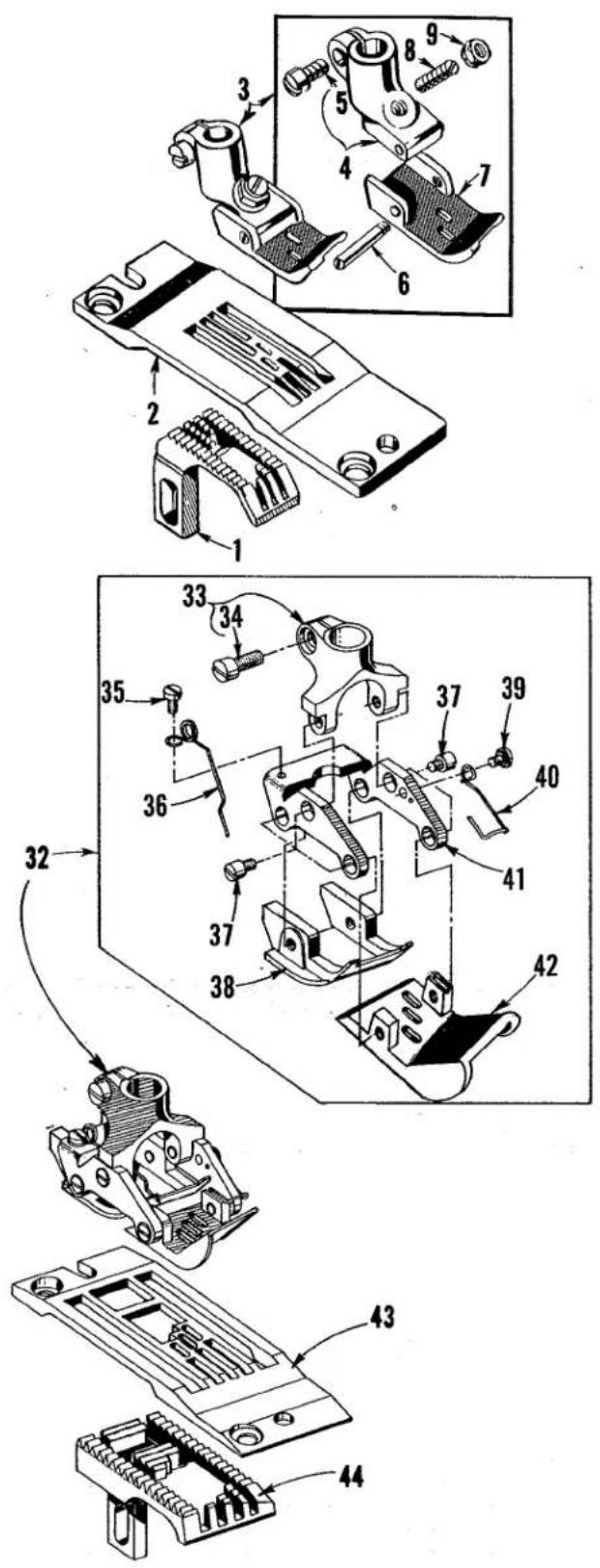
text_image
Technical diagram of a mechanical assembly with numbered parts, likely an electrical or mechanical component.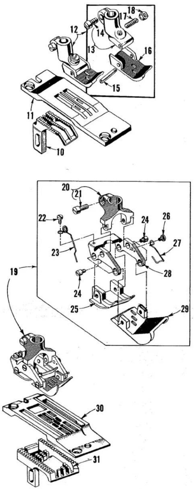
text_image
Technical diagram of mechanical assembly with numbered parts, showing exploded and assembled views of componentsSEWING COMBINATIONS
| Ref.No. | PartNo. | Description | Amt.Req. |
| 1 | 51405 A-10 | Feed Dog, for Style XF512E100MP-12 | 1 |
| 2 | 51424 A-12 | Throat Plate, for Style XF512E100MP-12 | 1 |
| 3 | 51420-12 | Presser Foot Assembly, for Style XF512E100MP-12 | 1 |
| 4 | 51430 D | Presser Foot Shank | 1 |
| 5 | 91 | Screw | 1 |
| 6 | 22799 B | Screw, hinge | 1 |
| 7 | 51430 A-12 | Presser Foot Bottom | 1 |
| 8 | 22840 A | Screw, adjusting | 1 |
| 9 | 51430 F | Nut, adjusting | 1 |
| 10 | 51405-16 | Feed Dog, for Style XF512E100MP-16 | 1 |
| 11 | C51424-16 | Throat Plate, for Style XF512E100MP-16 | 1 |
| 12 | 51420-16 | Presser Foot Assembly for Style XF512E100MP-16 | 1 |
| 13 | 51430 D | Presser Foot Shank | 1 |
| 14 | 91 | Screw | 1 |
| 15 | 22799 B | Screw, hinge | 1 |
| 16 | 51430 A-16 | Presser Foot Bottom | 1 |
| 17 | 22840 A | Screw, adjusting | 1 |
| 18 | 51430 F | Nut, adjusting | 1 |
| 19 | 56920 R-9 | Presser Foot Assembly, for Styles XF513E100HR-9, 101HR-9 and 112HR-9 | 1 |
| 20 | 35830 B | Presser Foot Shank | 1 |
| 21 | 91 D | Screw | 1 |
| 22 | 73 A | Screw | 1 |
| 23 | 35830 H | Spring | 1 |
| 24 | 22845 A | Screw | 6 |
| 25 | 56930 B | Presser Foot Bottom (rear section) | 1 |
| 26 | 22599 | Screw | 1 |
| 27 | 35830 K | Spring | 1 |
| 28 | 35830 C | Yoke | 1 |
| 29 | 35830 R-9 | Presser Foot Bottom (front section) | 1 |
| 30 | C56924 R-9 | Throat Plate, for Styles XF513E100HR-9 and 101HR-9 | 1 |
| - | C50024 Y-9 | Throat Plate, for Style XF513E112HR-9 | 1 |
| 31 | 56905 R-9 | Feed Dog, for Styles XF513E100HR-9, 101HR-9 and 112HR-9 | 1 |
| 32 | 50320 M-8 | Presser Foot Assembly, for Style XF513E100HJ-8 | 1 |
| - | 56920 A-9 | Presser Foot Assembly, for Style XF513E100HJ-9 | 1 |
| 33 | 35830 B | Presser Foot Shank | 1 |
| 34 | 91 D | Screw | 1 |
| 35 | 73 A | Screw | 1 |
| 36 | 35830 H | Spring | 1 |
| 37 | 22845 A | Screw | 6 |
| 38 | 50330 BF-8 | Presser Foot Bottom (rear section) for Style XF513E100HJ-8 | 1 |
| - | 56930 | Presser Foot Bottom (rear section) for Style XF513E100HJ-9 | 1 |
| 39 | 22599 | Screw | 1 |
| 40 | 35830 K | Spring | 1 |
| 41 | 35830 C | Yoke | 1 |
| 42 | 35830 R-8 | Presser Foot Bottom (front section) for Style XF513E100HJ-8 | 1 |
| - | 35830 R-9 | Presser Foot Bottom (front section) for Style XF513E100HJ-9 | 1 |
| 43 | 50324 N-8 | Throat Plate, for Style XF513E100HJ-8 | 1 |
| - | C56924 A-9 | Throat Plate, for Style XF513E100HJ-9 | 1 |
| 44 | 56905 A-9 | Feed Dog, for Styles XF513E100HJ-8 and XF513E100HJ-9 | 1 |
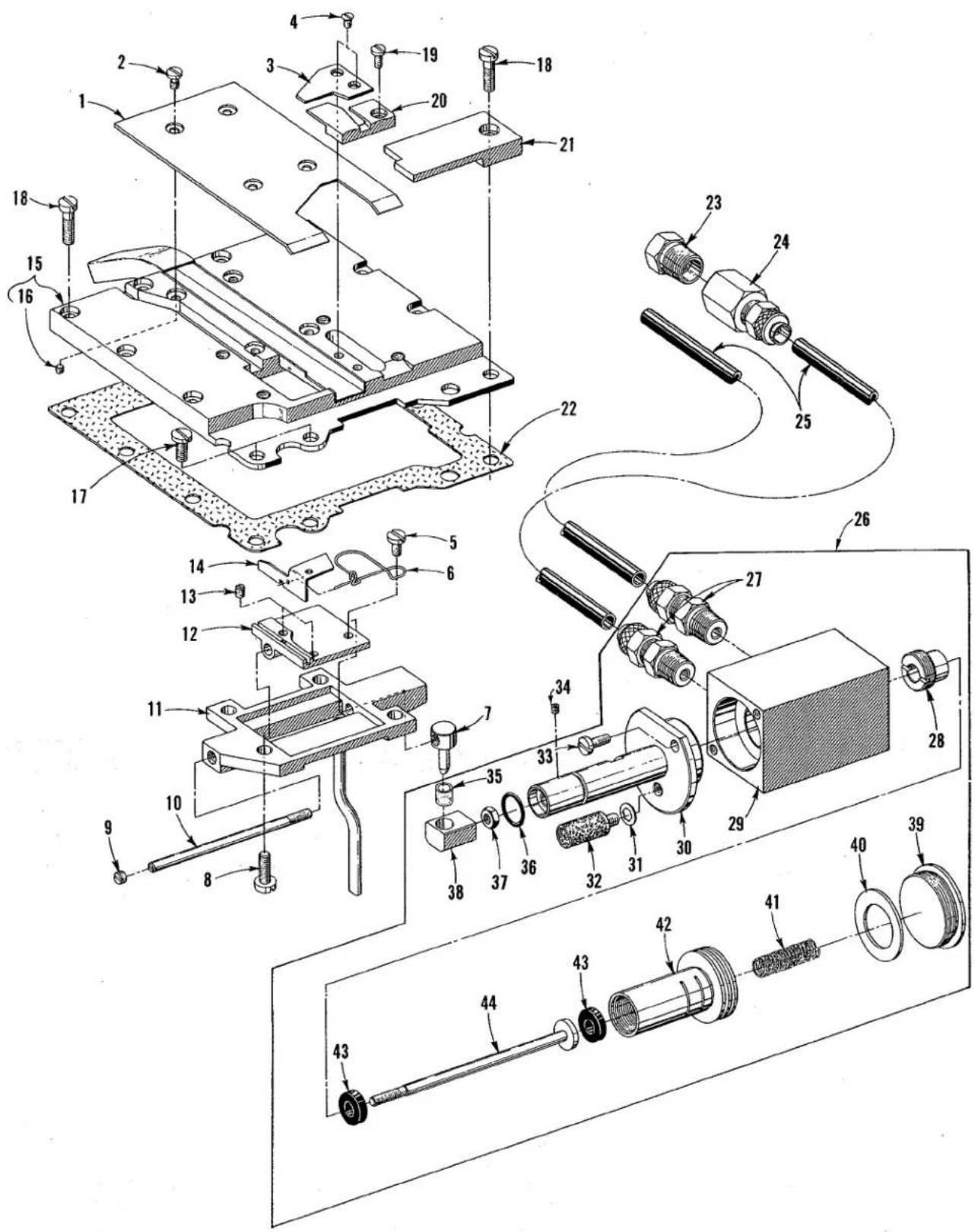
text_image
Technical diagram of a mechanical assembly with numbered components for identification and assembly reference.POWER "AIR-KLIPP" CHAIN CUTTER AND RELATED PARTS
(Styles XF511H112MF, 112MG, 151MF, XF511E152MF and XF513E112HR-9)
| Ref.No. | PartNo. | Description | Amt.Req. |
| 1 | 99679 SG | Cover, suction tube; for all Styles exceptXF513E112HR-9 | 1 |
| *- | 99679 SH | Cover, suction tube; for Style XF513E112HR-9 | 1 |
| 2 | 99312 A | Screw | 4 |
| 3 | 99670 SH | Knife, upper | 1 |
| 4 | 77 K | Screw | 2 |
| 5 | 357 | Screw | 1 |
| 6 | 99697 SA | Spring, knife | 1 |
| 7 | 99672 SB | Pin, coupling | 1 |
| 8 | 93 | Screw | 4 |
| 9 | 22560 | Screw | 1 |
| 10 | 99672 SA | Rod, knife drive | 1 |
| 11 | 99691 SA | Housing | 1 |
| 12 | 99671 SA | Holder, knife | 1 |
| 13 | 99346 T | Screw | 2 |
| 14 | 99669 K | Knife, lower | 1 |
| 15 | 99679 SA | Plate, cloth (rear) for all Styles except XF513E112HR-9 | 1 |
| *- | 99679 SB | Plate, cloth (rear) for Style XF513E112HR-9 | 1 |
| 16 | 28 B | Screw | 4 |
| 17 | 22569 G | Screw | 2 |
| 18 | 22572 A | Screw | 9 |
| 19 | 22768 | Screw, inlet; for all Styles except XF513E112HR-9 | 1 |
| *- | 22716 | Screw, inlet; for Style XF513E112HR-9 | 2 |
| 20 | 99677 SA | Inlet for all Styles except XF513E112HR-9 | 1 |
| *- | 99677 SC | Inlet, (right) for Style XF513E112HR-9 | 1 |
| *- | 99677 SB | Inlet, (left) for Style XF513E112HR-9 | 1 |
| 21 | 99679 SF | Plate, cover for all Styles except XF513E112HR-9 | 1 |
| *- | 99679 SE | Plate, cover for Style XF513E112HR-9 | 1 |
| 22 | C50082 E | Gasket | 1 |
| 23 | 660-763 | Muffler | 1 |
| 24 | 671 F-66 | Connector, female | 1 |
| 25 | RM2997 D | Tubing, plastic; 5 feet (approx. 1.5m) required | - |
| 26 | 671 H-2 | Air-Motor Assembly | 1 |
| 27 | 660-400 | Fitting, straight compression, 5/16 inch O.D. | 2 |
| 28 | 671 H-1E | Screw, plug | 1 |
| 29 | 671 H-2A | Housing | 1 |
| 30 | 671 H-2B | Flange, guide | 1 |
| 31 | 999-166 | Gasket, washer | 1 |
| 32 | 999-140 B | Muffler | 1 |
| 33 | 22585 | Screw | 2 |
| 34 | 22894 C | Screw, set for 671 H-2 | 1 |
| 35 | 671 H-1G | Insert, plastic (coupling pin) | 1 |
| 36 | 660-207 | "O" Ring | 1 |
| 37 | 41071 G | Nut, lock | 1 |
| 38 | 671 H-2D | Coupling, rod end | 1 |
| 39 | 671 H-1D | Screw, plug | 1 |
| 40 | 671 H-1F | Washer, stop | 1 |
| 41 | 660-753 | Spring | 1 |
| 42 | 671 H-1A | Piston, drive | 1 |
| 43 | 671 H-1H | Washer, shock absorbing | 2 |
| 44 | 671 H-2C | Rod, piston | 1 |
| 671 C-18 | Nut & sleeve for 5/16 inch O.D. fittings (shown with fittings) as req. | ||
| V29944 A | Power "AIR-KLIPP" Assembly includes Ref. Nos. 1 through 16. | ||
| *V29944 B | Power "AIR-KLIPP" Assembly includes Ref. Nos. 1 through 16 including components for XF513E112HR-9. | ||

text_image
5 4 2 3 6 7 8 9 10 11 12 13 14 15 16 17 18 19 20 21 22 23 24 25 26 27 28 29 30 31 32 33 34 35 36 37 38 39 40 41 42 43 44 45 46 47 48 TO TREADLE VALVE FOR OPTIONAL ACCESSORIES TO TREADLE COOLERPNEUMATIC CONTROLS
| Ref.No. | PartNo. | Description | *Amt.Req. | **Amt.Req. |
| 1 | 29480 ACB | * Pneumatic Control Board Assembly for all "AIR-KLIPP" Styles | 1 | - |
| - | 29480 ACW | ** Pneumatic Control Board Assembly for all Styles without "AIR-KLIPP" | - | 1 |
| 2 | 661-3 | Clamp, mounting | 2 | 2 |
| 3 | 22650 CF-6 | Screw, set | 2 | 2 |
| 4 | 652 B-16 | Washer, lock | 2 | 2 |
| 5 | 22635 D-6 | Screw | 2 | 2 |
| 6 | 35032 R | Bracket, mounting | 1 | 1 |
| 7 | 11635 B | Nut | 4 | 2 |
| 8 | 652 B-20 | Washer, lock | 4 | 2 |
| 9 | 671 D-5 | Filter | 1 | 1 |
| 10 | RM3320-1 | Reducer | 1 | 1 |
| 11 | RM2850 D | Tee, pipe | 2 | 2 |
| 12 | 22571 F | Screw, plug | 1 | 1 |
| 13 | RM3287-2 | Nipple, hex | 1 | 1 |
| 14 | 671 C-16 | Stud, mounting | 4 | 2 |
| 15 | 671 D-9 | Regulator | 4 | 2 |
| 16 | 671 F-69 | Fitting, swivel; 90 degree | 7 | 5 |
| 17 | 671 D-15 | Gauge | 4 | 2 |
| 18 | RM4098-1 | Valve, pilot | 1 | 1 |
| 19 | 660-403 | Muffler | 1 | 1 |
| 20 | RM2881-1 | Elbow, 90 degree | 1 | - |
| 21 | 671 F-94 | Tee, run | 1 | - |
| 22 | 50394 AB | Tube, air; 1/4 inch (6.35mm) | 1 | - |
| 23 | 671 F-96 | Tee, tube | 1 | - |
| 24 | 660-392 | Tube, air; 1/4 inch (6.35mm) | 3 | 1 |
| 25 | 671 F-3 | Fitting, tube; 3/8 inch (9.52mm) | 1 | - |
| 26 | 671 B-11 | Tube, discharge; for "AIR-KLIPP" Styles | 1 | |
| 27 | 671 D-2 | Venturi, for "AIR-KLIPP" Styles | 1 | |
| 28 | 671 B-3 | Tube, venturi; air supply for "AIR-KLIPP" Styles | 1 | |
| 29 | 998-332 | Holder, venturi; for "AIR-KLIPP" Styles | 1 | |
| 30 | RM2719-1 | Screw, wood; for "AIR-KLIPP" Styles | 2 | |
| 31 | 671 B-12 | Tube, suction; for "AIR-KLIPP" Styles | 1 | |
| 32 | RM2871 B | Tie | 4 | |
| 33 | RM3832-1 | Wrap, harness | 1 | |
| 34 | 29480 ACD | Treadle Valve Assembly | 1 | |
| 35 | 999-146 | Link | 2 | |
| 36 | 95250 | Nut | 2 | |
| 37 | 95250 | Nut | 3 | |
| 38 | 99563 A-75 | Rod, pitman | 1 | |
| 39 | C50036 AS | Collar, actuating | 2 | |
| 40 | 22894 R | Screw | 2 | |
| 41 | 671-135 | Bracket, mounting | 1 | |
| 42 | 22571 F | Screw, plug; used without optional accessories | 1 | |
| 43 | 671 F-69 | Fitting, swivel; 90 degree | 2 | |
| 44 | SC191 | Screw | 3 | |
| 45 | 671-134 | Body, valve | 1 | |
| 46 | 99563 A-130 | Rod, pitman | 2 | |
| 47 | G28562 A | Connector, rod (Pitman) | 1 | |
| 48 | 95051 | Screw | 1 |

text_image
Exploded view diagram of a mechanical assembly with numbered parts for identificationTHREAD STAND AND ACCESSORIES
| Ref. No. | Part No. | Description | Amt. Req. |
| 1 | 29480 ADL | Knee Press Assembly | 1 |
| *2 | 50364 H | Bracket, mounting | 1 |
| 3 | 667 C-16 | Pin, dowel | 1 |
| 4 | AS-7-2 | Base, knee press | 1 |
| 5 | RM3263-5 | Washer | 2 |
| 6 | 22653 B-12 | Screw | 2 |
| 7 | 671 F-69 | Fitting, swivel; 90 degree | 2 |
| 8 | 671-85 | Valve, three way | 1 |
| 9 | RM2805-1 | Screw | 2 |
| 10 | AS-7-1 | Rod, knee press | 1 |
| 11 | AS-7-3 | Press, knee | 1 |
| 12 | 69 FD | Screw | 1 |
| 13 | 660-168 | Pad, knee press | 1 |
| 14 | 21101 W-2 | Thread Stand Assembly for single needle machines | 1 |
| - | 21101 W-4 | Thread Stand Assembly for two needle machines | 1 |
| - | 21101 W-6 | Thread Stand Assembly for three needle machines | 1 |
| 15 | 21374 R | Shaft, presser foot treadle | 1 |
| 16 | 21374 N | Bracket, treadle shaft mounting | 3 |
| 17 | RM3162-2 | Screw | 6 |
| 18 | 652-16 | Washer | 6 |
| 19 | RM2791-3 | Nut | 6 |
| 20 | 21374 P | Treadle, presser foot | 1 |
| 21 | 22651 CD-4 | Screw | 2 |
| 22 | 21205 B | Wrench, stitch length adjusting | 1 |
| 23 | 21207 B | Screwdriver | 1 |
| 24 | 660-240 | Tweizer, thread | 1 |
| 25 | 21205 C | Wrench, stitch length adjusting for puller machines | 1 |
| 26 | 21374 C | Cradle Assembly, machine | 1 |
| 27 | 22604 | Screw | 2 |
| 28 | RM3293-3 | Washer | 30 |
| 29 | C50095 C | Retainer, isolator | 1 |
| 30 | C50095 | Screw, mounting | 1 |
| 31 | 651 B-16 | Nut | 1 |
| 32 | 651 B-24 | Nut | 4 |
| 33 | 11698 L | Nut | 19 |
| 34 | 22604 | Screw | 2 |
| 35 | 22640 M-96 | Screw | 3 |
| 36 | 22638 C | Screw, flat head | 4 |
| 37 | SC170 | Screw, flat head | 4 |
| 38 | 21374 D | Bracket, frame mounting | 4 |
| 39 | 21371 LR | Nut, cap | 4 |
| 40 | 21374 U | Spacer, table board | 4 |
| 41 | 28561 M | Rod Assembly, pitman | 1 |
| 42 | 22508 | Screw | 4 |
| 43 | 28562 A | Connection, pitman | 2 |
| 44 | 1453 R | Rod, pitman | 2 |
| 45 | 21374 T | Joint, connecting | 2 |
| 46 | C50095 C | Retainer, isolator | 6 |
| 47 | 51295 A | Isolator | 7 |
| 28604 S | Container of oil, 32 ounces (946ml.) spec 175, (not shown) | 1 |
*Mounting Bracket for Knee Press Assembly is applicable for use with right or left knee.
GENERAL PREVENTIVE MAINTENANCE SCHEDULE
| XF500 TASK | DAILY | AFTER FIRST MONTH | EVERY MONTH | EVERY -3-MONTHS | EVERY -6-MONTHS | YEARLY |
| Check oil level (sight gauge) oil level between red lines. | XF500 | |||||
| Check pump operation (oil flow indicator-top of arm). | XF500 | |||||
| Clean lint & dirt from machine. | XF500 | |||||
| Check that all guards and shields are in place and being used. | XF500 | |||||
| Change oil-filter. | XF500 | XF500 | ||||
| Change oil (oil which conforms to U.S.C. spec. 175 must be used). | XF500 | XF500 | ||||
| Check tension on internal timing belts. | XF500 | XF500 | ||||
| Inspect clutch/ positioner motor V-belt tension and wear. | XF500 | |||||
| Check clutch motor clutch/brake. | XF500 | |||||
| Clean lint from oil cooler. | XF500 | XF500 | ||||
| Clean lint from clutch/positioner motor air passages. | XF500 | XF500 | ||||
| Check needle/s bent, blunt, sharp or worn eye or groove. | XF500 |
NOTE: SCHEDULING IS BASED ON NORMAL WORKING CONDITIONS. FREQUENCY OF TASKS DEPENDS ON MACHINE DUTY CYCLE TIME AND PERSONNEL RESPONSIBLE TO PERFORM TASK DETERMINED BY PLANT MANAGEMENT.
NUMERICAL INDEX OF PARTS
| Part No. | Page No. | Part No. | Page No. | Part No. | Page No. |
| AS-7-1 | 71 | 136 | 55,57,59 | 660-757 | 41 |
| AS-7-2 | 71 | 141 | 41 | 660-762 | 39 |
| AS-7-3 | 71 | 158 A | 51 | 660-763 | 67 |
| 18 | 57 | SC170 | 71 | 660-855 | 31 |
| 18-71 | 61 | 187 A | 43 | 660-884 | 45 |
| 18-799 | 51 | SC191 | 69 | 660-885 | 31 |
| 18-1077 | 51 | 303 | 41 | 660-886 | 39 |
| HA20 A | 41,43 | 357 | 67 | 660-886 A | 55 |
| AS22 D | 59 | 531 | 49,51 | 660-886 B | 55 |
| 24 | 53 | 538 A | 61 | 660-886 C | 55 |
| 25 | 53 | 604 | 55,57,59, | 660-887 | 57,59 |
| 25 C | 61 | 63 | 660-888 | 55 | |
| 25 E | 53 | 605 A | 43,53 | 660-889 | 55 |
| 28 | 61 | 627 A | 49 | 660-890 | 55 |
| 28 B | 67 | 651 B-16 | 71 | 660-891 B | 55 |
| RI-37 | 31 | 651 B-24 | 71 | 660-891 C | 55 |
| 50 J-26 | 61 | 652-16 | 71 | 660-892 A | 57,59 |
| 50-216 BLK | 41 | 652 B-16 | 69 | 660-892 B | 57,59 |
| 51-627 BLK | 35 | 652 B-20 | 69 | 660-892 C | 55 |
| 51-673 BLK | 39 | 660-93 | 39 | 660-893 | 55 |
| 51-716 BLK | 57,59 | 660-168 | 71 | 660-896 | 37 |
| 57 WB | 51,53 | 660-206 | 33,39 | 660-914 | 55 |
| 57 WC | 51 | 660-207 | 41,67 | 660-918 | 55 |
| 57 WD | 51 | 660-219 A | 37 | 660-989 | 39 |
| C067 D | 43 | 660-219 L | 59 | 661-1 | 35 |
| C067 F | 35 | 660-220 | 31,39,57, | 661-3 | 69 |
| C067 H | 35 | 59 | 661-70 A | 55 | |
| 69 FD | 71 | 660-240 | 71 | 666-32 | 35 |
| 73 | 31 | 660-330 | 59 | 666-294 | 31,33 |
| 73 A | 41,61,63,65 | 660-392 | 69 | 666-311 | 35 |
| 660-400 | 39,67 | 666-322 | 31 | ||
| 77 K | 67 | 660-403 | 69 | 667 C-8 | 57,59 |
| 79-31 | 31 | 660-416 | 59 | 667 J-33 | 41 |
| 87 | 35,37,45 | 660-443 | 41 | 667 M-14 | 49 |
| 87 U | 41 | 660-445 | 41 | 667 C-16 | 71 |
| 88 | 41,63 | 660-677 | 43 | 670 E-2 | 31,55 |
| 88 B | 45,61 | 660-680 | 39 | 671-17 | 39 |
| 88 D | 45 | 660-683 | 31,43,45 | 671-85 | 71 |
| 88 F | 57,59,61 | 660-684 | 33 | 671-134 | 69 |
| 89-64 | 47 | 660-688 | 41 | 671-135 | 69 |
| 91 | 63,65 | 660-708 | 39 | 671 A-65 | 47 |
| 91 A | 63 | 660-713 | 39 | 671 B-3 | 69 |
| 91 D | 65 | 660-718 | 49 | 671 B-11 | 69 |
| 93 | 49,67 | 660-719 | 41 | 671 B-12 | 69 |
| 94 | 59 | 660-721 A | 39 | 671 C-4 | 31,39 |
| 95 | 43 | 660-721 C | 39 | 671 C-16 | 69 |
| 96 A | 43 | 660-731 | 53 | 671 C-18 | 67 |
| 98 | 41,43,55,57,59 | 660-739 | 33,35,37 | 671 D-2 | 69 |
| 660-749 | 31 | 671 D-5 | 69 | ||
| 98 A | 47,51 | 660-750 | 31 | 671 D-9 | 69 |
| 109 | 51 | 660-753 | 67 | 671 D-15 | 69 |
NUMERICAL INDEX OF PARTS
| Part No. | Page No. | Part No. | Page No. | Part No. | Page No. |
| 671 | F-3......69 | 9937......45 | 22541 | A......45 | |
| 671 | F-4......31,39 | 11635 B......69 | 22541 | C......33,37 | |
| 671 | F-19......55 | 11698 L......71 | 22541 | D......47 | |
| 671 | F-41......31,55 | 12934 A......37 | 22552 | A-16......47 | |
| 671 | F-64......55 | 14077......45 | 22557 | J......49 | |
| 671 | F-66......67 | 15037 A......49 | 22560 | ......67 | |
| 671 | F-69......47,69,71 | 15438 C......53 | 22560 | B......55,57,59,63 | |
| 671 | F-71......39 | 21101 W-2......71 | |||
| 671 | F-73......39 | 21101 W-4......71 | 22562 | ......63 | |
| 671 | F-94......69 | 21101 W-6......71 | 22562 | A......47 | |
| 671 | F-96......69 | 21192 R......37 | 22562 | B-10......61 | |
| 671 | H-1A......67 | 21205 B......71 | 22565 | X......61 | |
| 671 | H-1D......67 | 21205 C......71 | 22569 | B......37,41 | |
| 671 | H-1E......67 | 21207 B......71 | 22569 | C......33,37,49,51 | |
| 671 | H-1F......67 | 21210......61 | |||
| 671 | H-1G......67 | 21237 DF......39 | 22569 | D......53 | |
| 671 | H-1H......67 | 21237 DG......39 | 22569 | G......35,37,41,67 | |
| 671 | H-2......67 | 21237 DP......39 | |||
| 671 | H-2A......67 | 21237 DR......39 | 22569 | J......53 | |
| 671 | H-2B......67 | 21237 DU......39 | 22569 | M......37 | |
| 671 | H-2C......67 | 21237 EA......39 | 22569 | U......39 | |
| 671 | H-2D......67 | 21371 LR......71 | 22569 | V......37 | |
| 998-332......69 | 21374 C......71 | 22569 | W......37 | ||
| 999-140 B......67 | 21374 D......71 | 22570 | ......35,63 | ||
| 999-146......69 | 21374 N......71 | 22570 | A......43,45 | ||
| 999-166......67 | 21374 P......71 | 22570 | E......57 | ||
| 1453 R......71 | 21374 R......71 | 22571 | E......33 | ||
| 1740......63 | 21374 T......71 | 22571 | F......69 | ||
| RM2719-1......69 | 21374 U......71 | 22572 | A......67 | ||
| RM2791-3......71 | 21375 BW......59 | 22574 | D......55 | ||
| RM2805-1......71 | 21375 BX......55 | 22580 | ......61 | ||
| RM2850 D......69 | 21375 BY......55 | 22580 | D......41 | ||
| RM2871 B......69 | 21756 G......47 | 22585 | ......67 | ||
| RM2879-2......37 | 22501 A......51 | 22585 | A......53 | ||
| RM2881-1......69 | 22508......71 | 22585 | U......37 | ||
| RM2964 B......39,55 | 22513......53 | 22587 | N......35 | ||
| RM2997 D......47,67 | 22516......41 | 22592 | B......33 | ||
| RM3162-2......71 | 22516 A......43 | 22593 | ......55 | ||
| RM3211-1......47 | 22516 B......43 | 22594 | ......43 | ||
| RM3263-5......71 | 22517......37,43 | 22596 | H......45,49 | ||
| RM3287-2......69 | 22519 H......43 | 22597 | E......37,39 | ||
| RM3293-3......71 | 22519 K......49 | 22599 | ......65 | ||
| RM3320-1......69 | 22519 M......43 | 22604 | ......71 | ||
| RM3633-1......39,55 | 22520......41,53 | 22635 | D-6......69 | ||
| RM3728-1......31 | 22521......35 | 22635 | G-16......53 | ||
| RM3832-1......69 | 22524......55 | 22637 | P-24......43 | ||
| RM4098-1......69 | 22526......59 | 22638 | C......71 | ||
| 6042 A......59 | 22526 H......37 | 22640 | M-96......71 | ||
| 8372 A......57,59 | 22528......41 | 22640 | R-40......47 | ||
| 9846......45 | 22539 G......35 | 22650 | CF-6......69 | ||
| 9846 A......41 | 22541......33 | 22651 | CD-4......41,71 |
NUMERICAL INDEX OF PARTS
| Part No. | Page No. | Part No. | Page No. | Part No. | Page No. |
| 22652 | A-6......47 | 22840 | C......49 | V29944 | A......67 |
| 22652 | A-8......39,41 | 22845 | A......65 | V29944 | B......67 |
| 22652 | A-20......33 | 22845 | R......43 | 35032 | R......69 |
| 22652 | B-10......45 | 22851 | A......33 | 35818 | N-8......61 |
| 22652 | B-12......31,45 | 22851 | D......37 | 35830 | B......65 |
| 22652 | J-10......61 | 22861 | C......37 | 35830 | C......65 |
| 22653 | B-12......71 | 22868 | C......43 | 35830 | H......65 |
| 22653 | J-4......39 | 22872 | ......53 | 35830 | K......65 |
| 22653 | J-8......41 | 22881 | B......33 | 35830 | R-8......65 |
| 22716 | ......67 | 22881 | C......61 | 35830 | R-9......65 |
| 22716 | A......53 | 22882 | ......49 | 39198 | D......45 |
| 22720 | A......31,39 | 22882 | D......39 | 39592 | AK......51 |
| 22720 | B......31 | 22883 | B......37 | 39656 | A......59 |
| 22726 | L......51 | 22891 | D......43 | 39868 | H......53 |
| 22729 | B......41 | 22894 | C......39,49,67 | 41071 | G......39,45,63,67 |
| 22729 | L......47 | 22894 | E......39,59 | ||
| 22729 | AA......45 | 22894 | J......55 | 41350 | X......39 |
| 22730 | ......31,39 | 22894 | K......35,43 | 41391 | ......43 |
| 22731 | ......41 | 22894 | L......41,49 | C50001 | A......37 |
| 22733 | ......35 | 22894 | P......49 | C50001 | B......37 |
| 22738 | M......43 | 22894 | R......39,57,69 | C50001 | C......37 |
| 22743 | ......47,61 | 22894 | W......45,49,59 | C50001 | D......53 |
| 22752 | ......61 | 22894 | AD......39,41 | C50001 | E......37 |
| 22758 | ......49 | 22894 | AE......39,41 | C50001 | G......37 |
| 22758 | E......47 | 22894 | AM......57,59 | C50001 | J......37 |
| 22758 | K......47 | 23420 | S-9-1/8......61 | C50004 | ......41 |
| 22760 | A......61 | 23421 | S-9-1/8......61 | C50005 | F......63 |
| 22764 | ......33,47 | 23421 | U-12-1/16......61 | C50005 | G......63 |
| 22768 | ......41,67 | 23421 | U-16-1/16......61 | C50013 | ......61 |
| 22768 | A......61 | 23421 | U-16-3/32......61 | C50013 | A......61 |
| 22778 | A......45 | 23421 | U-18-3/32......61 | C50013 | B......61 |
| 22784 | E......33 | 23422 | U-1/16......61 | C50013 | D......61 |
| 22784 | M......63 | 23422 | AY-18-1/8......61 | C50014 | ......41 |
| 22784 | N......39 | 23422 | BZ-3/32......61 | C50014 | A......41 |
| 22785 | ......61,63 | 23423 | S......61 | C50017 | A......61 |
| 22789 | A......47 | 23424 | S......61 | C50017 | C......61 |
| 22792 | A......53 | 23425 | V......61 | C50018 | B-9......61 |
| 22797 | B......41 | 28561 | M......71 | C50018 | D......61 |
| 22799 | B......63,65 | 28562 | A......71 | C50018 | L-12......61 |
| 22799 | E......63 | G28562 | A......69 | C50018 | L-16......61 |
| 22799 | G......63 | 28604 | S......71 | C50020 | ......63 |
| 22799 | AH......53 | 28633 | L......57,59 | C50021 | A......39 |
| 22804 | ......43 | 29105 | AP......41 | C50021 | C......41 |
| 22806 | D......39 | 29192 | AE......41 | C50021 | D......41 |
| 22824 | B......55 | 29476 | PY......51 | C50021 | E......39 |
| 22825 | ......55 | 29476 | PX......51 | C50021 | F......41 |
| 22837 | ......51 | 29480 | ACB......69 | C50022 | A......41 |
| 22839 | ......35 | 29480 | ACD......69 | C50022 | C......49 |
| 22839 | A......41 | 29480 | ACW......69 | C50022 | D......49 |
| 22839 | G......43 | 29480 | ADL......71 | C50022 | G......43 |
| 22840 | A......65 | 29480 | XA......39 | C50022 | J......39 |
NUMERICAL INDEX OF PARTS
| Part No. | Page No. | Part No. | Page No. | Part No. | Page No. |
| C50022 | K......59 | C50035 | T......43 | C50042 | AB-16......55 |
| C50022 | L......55 | C50035 | V......45 | C50042 | AC-16......55 |
| C50022 | N......59 | C50035 | W......45 | C50042 | AD......41 |
| C50023 | E......41 | C50035 | X......45 | C50042 | AE......59 |
| C50023 | F......41 | C50035 | Y......35 | C50042 | AF......55 |
| C50023 | G......41 | C50035 | Z......35 | C50042 | AG......55 |
| C50024 | B......63 | C50035 | AA......45 | C50042 | AJ-12......57 |
| C50024 | D......63 | C50035 | AB......45 | C50042 | AK......57 |
| C50024 | E......63 | C50035 | AJ......45 | C50042 | AL......59 |
| C50024 | Y-9......65 | C50035 | AL......45 | C50043 | 39,41 |
| C50025 | ......61 | C50035 | AM......43 | C50043 | H-021......43 |
| C50025 | A......47 | C50035 | AN......45 | C50043 | H-025......43 |
| C50025 | E......61 | C50035 | AP......45 | C50043 | H-029......43 |
| C50025 | F......47 | C50035 | AR......43 | C50044 | A......41 |
| C50025 | N......61 | C50035 | AS......45 | C50044 | D......35 |
| C50030 | ......63 | C50035 | AW......47 | C50044 | F......35 |
| C50030 | A......63 | C50035 | AX......47 | C50044 | G......35 |
| C50030 | B......63 | C50035 | AY......47 | C50044 | T......53 |
| C50030 | C......63 | C50035 | AZ......47 | C50044 | V......41 |
| C50030 | D......63 | C50035 | BA......47 | C50045 | B......43 |
| C50031 | ......63 | C50035 | BC......45 | C50047 | G......43 |
| C50032 | ......53 | C50036 | ......43 | C50049 | 37 |
| C50032 | B......37 | C50036 | A......43 | C50049 | A......35 |
| C50032 | C......53 | C50036 | B......43 | C50051 | X......35,45 |
| C50032 | D......37 | C50036 | C......43 | C50054 | D......35 |
| C50034 | D......43 | C50036 | D......43 | C50054 | M......51 |
| C50034 | F......43 | C50036 | E......43 | C50055 | 39 |
| C50034 | G......43 | C50036 | F......43 | C50055 | C......39 |
| C50034 | H......43 | C50036 | G......43 | C50055 | K......35 |
| C50034 | J......43 | C50036 | J......35 | C50055 | L......35 |
| C50034 | K......43 | C50036 | M......43 | C50055 | S......35 |
| C50034 | L......43 | C50036 | P......39,41 | C50055 | W......39 |
| C50034 | M......43 | C50036 | R......49,57,59 | C50055 | Y......39 |
| C50034 | N......43 | C50036 | U......35 | C50056 | B......49 |
| C50034 | V......43 | C50036 | AJ......49 | C50056 | C......49 |
| C50034 | X......43 | C50036 | AS......69 | C50056 | D......49 |
| C50034 | Z......43 | C50037 | A......45 | C50056 | J......49 |
| C50034 | AG......43 | C50037 | D......57 | C50056 | K......49 |
| C50034 | AH......43 | C50041 | D......61 | C50056 | L......49 |
| C50034 | AK......43 | C50041 | E......61 | C50057 | 41 |
| C50035 | ......45 | C50041 | F......61 | C50057 | A......41 |
| C50035 | A......43 | C50041 | G......61 | C50057 | B......41 |
| C50035 | B......43 | C50041 | H......61 | C50057 | C......41 |
| C50035 | F......43 | C50042 | F......41 | C50057 | D......35 |
| C50035 | G......35 | C50042 | G......41 | C50057 | E......49 |
| C50035 | K......43 | C50042 | H......41 | C50057 | K......49 |
| C50035 | H......45 | C50042 | M......39 | C50058 | A......53 |
| C50035 | P......45 | C50042 | Y......39 | C50058 | F......51 |
| C50035 | N......45 | C50042 | Z-13......55 | C50058 | H......61 |
| C50035 | R......45 | C50042 | Z-16......57 | C50058 | K......61 |
| C50035 | S......45 | C50042 | Z-18......59 | C50063 | Y......57 |
NUMERICAL INDEX OF PARTS
| Part No. | Page No. | Part No. | Page No. | Part No. | Page No. |
| C50067 | 49 | C50078 | W....57 | C50092 | J....51 |
| C50067 | A....49 | C50078 | X....57 | C50092 | L....51 |
| C50067 | B....49 | C50078 | Y....57 | C50092 | M....51 |
| C50067 | D....49 | C50078 | AA....57 | C50092 | N....53 |
| C50067 | F....49 | C50078 | AB....57 | C50092 | R....51 |
| C50067 | G....49 | C50078 | AC....57 | C50092 | S....51 |
| C50067 | K....49 | C50078 | AE....57 | C50092 | U....53 |
| C50067 | L....39 | C50078 | AF-10....59 | C50093 | 33 |
| C50068 | A....47 | C50078 | AF-15....59 | C50093 | F....33 |
| C50068 | B....47 | C50080 | 63 | C50093 | G....33 |
| C50068 | C....47 | C50080 | A....63 | C50093 | L....33 |
| C50068 | U....47 | C50080 | B....35 | C50093 | M....33 |
| C50068 | X....35 | C50080 | C....63 | C50093 | N....33 |
| C50068 | Y....47 | C50080 | AA....63 | C50093 | P....33 |
| C50068 | Z....47 | C50080 | AB....63 | C50093 | R....33 |
| C50068 | AG....35 | C50082 | B....37 | C50093 | S....33 |
| C50070 | B....51 | C50082 | C....37 | C50093 | T....33 |
| C50074 | ....59 | C50082 | D....35 | C50093 | U....33 |
| C50075 | ....37 | C50082 | E....35,67 | C50093 | Z....33 |
| C50075 | B....59 | C50082 | K....37 | C50093 | AA....33 |
| C50076 | ....59 | C50082 | L....37 | C50093 | AB....33 |
| C50076 | C....49 | C50082 | M....37 | C50093 | AE....33 |
| C50077 | ....59 | C50082 | N....37 | C50093 | AG....33 |
| C50077 | B....57,59 | C50082 | T....37 | C50093 | AH....33 |
| C50077 | C....57,59 | C50082 | U....37 | C50093 | AJ....33 |
| C50077 | D....57,59 | C50082 | V....37 | C50093 | AK....39 |
| C50077 | E....49 | C50082 | W....53 | C50093 | AN....33 |
| C50077 | F....49 | C50082 | X....37 | C50093 | AS....37 |
| C50077 | G....49 | C50082 | Y....53 | C50093 | AU....37 |
| C50077 | H....57,59 | C50082 | Z....53 | C50093 | AW....35 |
| C50077 | J....57,59 | C50082 | AA....37 | C50093 | AX....35 |
| C50077 | K....59 | C50082 | AH....53 | C50093 | AY....35 |
| C50077 | M....57 | C50082 | AJ....37 | C50093 | BC....41 |
| C50077 | N....57 | C50082 | AK....37 | C50093 | BE....31 |
| C50077 | P....41 | C50082 | AP....55 | C50093 | BH....33 |
| C50077 | AD....49 | C50082 | AR....55 | C50093 | BK....39 |
| C50078 | C....53 | C50082 | AW....37 | C50093 | BR....53 |
| C50078 | E....59 | C50082 | DA....35 | C50093 | BS....33 |
| C50078 | F....59 | C50082 | UA....37 | C50093 | BX....31 |
| C50078 | G....55 | C50090 | 41 | C50093 | CA....33 |
| C50078 | H....55 | C50090 | A....37 | C50093 | CB....33 |
| C50078 | J....55 | C50090 | B....41 | C50093 | CG....31 |
| C50078 | L....55 | C50090 | D....41 | C50093 | CH....31,45 |
| C50078 | M....55 | C50090 | E....35 | C50093 | CJ....31 |
| C50078 | N....55 | C50090 | F....35 | C50093 | CL....31 |
| C50078 | P....55 | C50090 | G....35 | C50093 | CM....31 |
| C50078 | R....59 | C50090 | J....49 | C50093 | CS....55 |
| C50078 | S....59 | C50090 | K....35 | C50093 | CT....35 |
| C50078 | T....59 | C50090 | M....49 | C50093 | CV....31 |
| C50078 | U....59 | C50090 | N....49 | C50093 | DB....35 |
| C50078 | V....59 | C50092 | G....51 | C50094 | 31 |
NUMERICAL INDEX OF PARTS
| Part No. | Page No. | Part No. | Page No. | Part No. | Page No. |
| C50094 B....31 | 50393 CX....35 | 56330 AJ....63 | |||
| C50094 C....31 | 50393 CY....31 | 56330 AK....63 | |||
| C50094 F....31 | 50393 CZ....35 | 56330 AP....63 | |||
| C50094 G....31 | 50393 DC....31 | 56330 AU....63 | |||
| C50094 P....31 | 50393 DD....35 | 56330 AV....63 | |||
| C50094 R....31 | 50394 AB....69 | 56330 AW....63 | |||
| C50094 U....31 | 51192 B....53 | 56330 AX....63 | |||
| C50094 V....31 | 51242 L....57,59 | 56335 D....43 | |||
| C50094 W....33 | 51280 K....63 | 56358 B....51 | |||
| C50094 X....39 | 51292 A....51 | 56358 C....51 | |||
| C50094 Y....31 | 51292 D....53 | 56358 D....51 | |||
| C50094 Z....31 | 51292 F-2....51 | 56392 E....51 | |||
| C50094 AA....31 | 51292 F-8....51 | 56392 F....51 | |||
| C50094 AC....31 | 51295 A....71 | 56505....63 | |||
| C50094 AF....55 | 51405 A-10....65 | 56520....63 | |||
| C50094 AJ....39 | 51405-16....65 | 56524 B-1....63 | |||
| C50094 AM....31 | 51408-16....61 | 56530....63 | |||
| C50095....33,71 | 51409....61 | 56530 A....63 | |||
| C50095 C....71 | 51420-12....65 | 56905 A-9....65 | |||
| C50095 D....37 | 51420-16....65 | 56905 R-9....65 | |||
| C50095 E....37 | 51424 A-12....65 | 56920 A-9....65 | |||
| C50095 F....37 | C51424-16....65 | 56920 R-9....65 | |||
| C50095 G....37 | 51430 A-12....65 | C56924 A-9....65 | |||
| 50304 D....51 | 51430 A-16....65 | C56924 R-9....65 | |||
| 50318 C....61 | 51430 D....65 | 56930....65 | |||
| 50320 M-8....65 | 51430 F....63,65 | 56930 B....65 | |||
| 50324....63 | 51480-12....61 | 56958....53 | |||
| 50324 N-8....65 | 51508 G-1....61 | 59451 F....55 | |||
| 50325 K....61 | 51509 C....61 | 61434 G....45 | |||
| 50330 BF-8....65 | 51530 D....63 | 63471....51 | |||
| 50354 D....35 | 51530 F....63 | 95051....69 | |||
| 50354 E....35 | 51530 G....63 | 95250....69 | |||
| 50358 G....61 | 51854 C....49 | 97127....37 | |||
| 50358 H....41 | 51908 B-8....61 | 99312 A....67 | |||
| 50358 J....51 | 51908 B-9....61 | 99346 T....67 | |||
| 50358 K....51 | 51909 C....61 | 99563 A-75....69 | |||
| 50364 H....71 | 51909 D-8....61 | 99563 A-130....69 | |||
| 50370....51 | 51909 D-9....61 | 99669 K....67 | |||
| 50370 A....51 | 51959 D....53 | 99670 SH....67 | |||
| 50375....59 | 52804 E....41 | 99671 SA....67 | |||
| 50375 A....59 | 52904 E....41 | 99672 SA....67 | |||
| 50375 B....59 | 52930 AC....57,63 | 99672 SB....67 | |||
| 50375 C....59 | 52958 D....41 | 99677 SA....67 | |||
| 50375 D....59 | 52958 G....53 | 99677 SB....67 | |||
| 50378 R....51 | 53193 B....39 | 99677 SC....67 | |||
| 50382 BN....37 | 53634 C....41,45,55, | 99679 SA....67 | |||
| 50382 BP....37 | 61 | 99679 SB....67 | |||
| 50390 D....61 | 56305 C....63 | 99679 SC....37 | |||
| 50392 B....51 | 56320 E....63 | 99679 SD....37 | |||
| 50393 V....31 | 56322 B....31,33,39, | 99679 SE....67 | |||
| 50393 AY....31 | 43 | 99679 SF....67 | |||
| 50393 AX....31 | C56324 C....63 | 99679 SG....67 | |||
| 50393 CF....39 | 56330 AD....63 | 99679 SH....67 | |||
| 50393 CS....31,35 | 56330 AF....63 | 99691 SA....67 | |||
| 50393 CU....31 | 56330 AG....63 | 99697 SA....67 | |||
| 50393 CV....35 | 56330 AH....63 |
NOTES
Union Special Corporation
Corporate Office
One Union Special Plaza
Huntley, IL 60142
Phone: 847·669·5101
Fax: 847·669·4454
Union Special GmbH
EuropeanDistributionCenter
Raiffeisenstrasse 3
D-71696 Möglingen, Germany
Tel: 49·07141·247·0
Fax: 49·07141·247·100
JUKI CORPORATION
INTERNATIONAL SALES DIVISION
8-2-1, KOKURYO - CHO,
Union Special INDUSTRIAL SEWING EQUIPMENT