SX199 - Headphones SRS - Free user manual and instructions
Find the device manual for free SX199 SRS in PDF.

User questions about SX199 SRS
0 question about this device. Answer the ones you know or ask your own.
Ask a new question about this device
Download the instructions for your Headphones in PDF format for free! Find your manual SX199 - SRS and take your electronic device back in hand. On this page are published all the documents necessary for the use of your device. SX199 by SRS.
USER MANUAL SX199 SRS
OpticallInterfaceController
SX199

Stanford Research Systems
Certification
StanfordResearchSystemscertifiesthatthisproductmetitspublishedspecificationsatthetime ofshipment.
Warranty
ThisStanfordResearchSystemsproductiswarrantedagainstdefectsinmaterialsandworkmanshipforaperiodofone(1)yearfromthedateofshipment.
Service
Forwarrantyserviceorrepair, thisproductmustbereturnedtoaStanfordResearchSystems authorizedservicefacility.ContactStanfordResearchSystemsoranauthorizedrepresentative beforereturningthisproductforrepair.
Informationinthisdocumentissubjecttochangewithoutnotice.
Copyright ©StanfordResearchSystems, Inc., 2013–2013. All rights reserved.
StanfordResearchSystems, Inc.
1290-DReamwoodAvenue
Sunnyvale, CA94089 USA
Phone:(408)744-9040•Fax:(408)744-9049
www.thinkSRS.com•e-mail:info@thinkSRS.com
PrintedinU.S.A.Documentnumber9-01692-903
Contents
GeneralInformationiii
SafetyandPreparationforUse......iii
Symbols......iv
Notation......v
Specifications......vi
1Introduction1-1
1.1 Introduction to the instrument......1-2
1.1.1FrontPanel....1-2
1.1.2 RearPanel....1-3
1.2Remoteconfiguration ....1-3
1.2.1 IEEE-488GPIB....1-3
1.2.2Ethernet 1-5
1.2.3RS-232 1-6
1.3Debugport ......1-6
2RemoteOperation
2-1
2.1Indexofcommands ......2-2
2.2Alphabeticlistofcommands....2-3
2.3Introduction 2-5
2.3.1Interfaceconfiguration .....2-5
2.3.2Buffers ......2-5
2.4Ethernet....2-5
2.5Linkmodel 2-6
2.6Commands 2-7
2.6.1 Commandsyntax ......2-7
2.6.2 Notation .....2-8
2.6.3Examples....2-8
2.6.4Linkcommands ......2-9
2.6.5Interfacecommands ......2-11
2.6.6Statuscommands ......2–14
2.7Statusmodel 2-17
2.7.1Statusbyte(SB) ......2-18
2.7.2Servicerequestenable(SRE)......2-18
2.7.3 Standardeventstatus(ESR) ......2–18
2.7.4Portstatusevent(PSEV) ......2–19
GeneralInformation
SafetyandPreparationforUse

WARNING
Dangerousvoltages, capable of causing injury or death, are present in this instrument. Donotremovethe product covers or panels. Donotapply power or operatethe product without all covers and panels in place.
AClinevoltage
The universal input powers supply of the SX199 Optical Interface Controller accommodates any voltage in the range 90 VAC to 260 VAC, with a frequency in the range 47 Hz to 63 Hz.
Linecord
The SX199OpticalInterfaceControllerhasadetachable, three-wire powercordforconnectiontothepowersourceandtoaprotective ground. The chassis of the instrument is connected to the outlet ground to protect against electrical shock. Always use an outlet which has a properly connected protective ground.
Fuse
The SX199 has an internal fuse that is not intended for service by the user.
If the POWER indicator does not illuminate when line power is applied and the powers switch in the "on" position, contact Stanford Research Systems for service.
Service
TheSX199OpticalInterfaceControllerdoesnothaveanyuserserviceablepartsinside.Referservicetoaqualifiedtechnician.
Donotinstallsubstitutepartsorperformanyunauthorizedmodificationstothisinstrument.Contactthefactoryforinstructionson how to return the instrument for authorized service and adjustment.
SymbolsyoumayFindonSRSProducts
| Symbol Description | |
 | Alternating current |
 | Caution - risk of electric shock |
 | Frame or chassis terminal |
 | Caution - refer to accompanying documents |
 | Earth (ground) terminal |
 | Battery |
 | Fuse |
| On (supply) | |
| Off (supply) | |
Notation
The following notation will be used throughout this manual.
WARNING
A warning mean that injury or death is possible if the instructions are not obeyed.
CAUTION
Acautionmeansthatdamagetotheinstrumentorotherequipment is possible.
Typesetting conventions used in this manual are:
- Front-panelindicatorsaresetasOverload
- Remotecommandnamesaresetas*IDN?
- LiteraltextotherthancommandnamesissetasOFF
Remote command examples will all beset in monospaced font. In these examples, data sent by the host computer to the SX199 areset as straight teletype font, while responses received by the host computer from the SX199 areset asslanted teletype font.
Specifications
Rearpanel
| ParameterSpecification | |
| OpticalportsFour(4),Avago“VersatileLink”,duplex,non-latching(matingpartHFBR-4506Z) | |
| RemoteInterfacesRS-232DB-9,9600/57.6kbaud,switchselectedGPIBEthernet10/100Base-T(auto) | |
| DebugportRS-232,DB-9 |
Opticalports
| ParameterSpecification | |
| Wavelength660nm(typ) | |
| Fiberopticlength3mstandard(HFBR-RMD003Z)10mavailable(HFBR-RMD010Z) |
General
| ParameterSpecification | |
| Temperature0 | °Cto40 °C,non-condensing |
| Power25W,90 | VACto260VAC,47Hzto63Hz |
| Dimensions8.25 | "W×4"H×11"D |
| Weight | 5lbs |
1 Introduction
ThischapterprovidesabasicoverviewoftheSX199OpticalInterface Controller.
InThisChapter
1.1 Introduction to the instrument......1-2
1.1.1FrontPanel....1-2
1.1.2 RearPanel....1-3
1.2 Remote configuration....1-3
1.2.1IEEE-488GPIB....1-3
1.2.2Ethernet....1-5
1.2.3RS-232....1-6
1.3Debugport......1-6
1.1 Introduction to the instrument
TheSX199OpticalInterfaceControllerisacommunicationsbridge toconnectuptofour(4)SRSinstrumentshavingaserialoptical interfacetoacomputer'sremoteinterfaceviaGPIB,ethernet,orRS-232.
1.1.1FrontPanel
ThefrontpaneloftheSX199(Figure1.1)providessimplemonitoring ofthestatusoftheremoteinterfaceandopticalportconnections. WheneverpowerisappliedandtheACswitchinthe"ON"position, theONpowerindicatorshouldbeilluminated.

text_image
NSRS STANFORD RESEARCH SYSTEMS MODEL SX199 Optical Interface Controller INTERFACE ● GPIB ● ETHERNET ● RS-232 To Opto ● From Opto ● ERROR PORT 1 2 3 4 POWER ● ONFigure1.1:TheSX199frontpanel.
Indicatorsintheleft-mostcolumnofthe"INTERFACE"blockindicatereal-timedatatrafficonthethreeremoteinterfaces(GPIB, ethernet,andRS-232).Anydatacomingfromorgoingtoaninterfacewill causethatinterfaceindicatortoflash.Ifdataisbeingtransmittedto one of the optical ports, then the To Opto indicator will also flash. If dataisbeingreceivedfromoneoftheopticalports,theFromOpto willilluminate.Commanderrorsorbufferoverrunswillcausethe ERRORindicatorortoilluminate.TheERRORindicatorisclearedby theremote*ESR?query.
When the SX199 is in the "link" state with an optical port, the selectedportisindicatedbythe"PORT"blockonthefrontpanel.The correspondinglinkedremoteinterfaceindicatorisalsoilluminated.
1.1.2 RearPanel
TherearpaneloftheSX199(Figure1.2)providesallexternalinterface connectionsandthepowerswitch.Theunitisturnedonwhenthe ACpowerswitchisinthe"1"position,andoffwhentheswitchisin the"0"position.

text_image
NSRS Stanford Research Systems - Model SX199 - Optical Interface Controller Port 1 transmit receive Port 2 transmit receive Port 3 transmit receive Port 4 Debug No user serviceable parts inside. Refer to operation manual for safety notice. For use by qualified laboratory personnel only. RS-232 Ethernet GPIB Made in the U.S.A. WARNING No user serviceable parts inside. Refer to operation manual for safety notice. For use by qualified laboratory personnel only. 11: Custom IP Address (Set via remote) 10: 192, 168, 0, (100 + Bus Addr.) 01: 18, 0, 0, (200 + Bus Addr.) 00: 169, 254, 100, (200 + Bus Addr.) RS-232 E: 9600, 1:57.6k S/N 126018 0 (off) 1 (on) Bus Address MADE IN U.S.A.Figure1.2:TheSX199rearpanel.
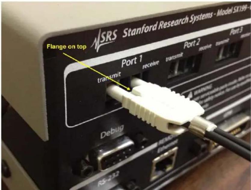
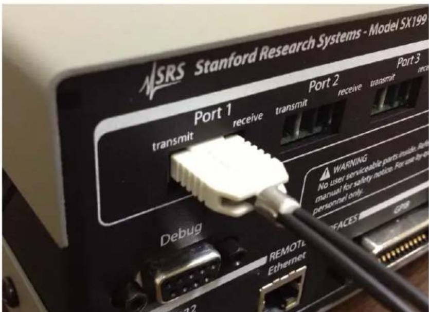
Theopticalportsareintheupperblockoftherearpanel,labeled "Port1" through"Port4".Whenmatingthefiberopticcableto oneoftheportconnections,besurethesmallflangeprotrusionis orientedupwards(Figure1.3.Onceorientedandaligned,pressthe cableconnectorinwardsuntil"clicks"inplace(Figure1.4).
1.2Remoteconfiguration
RemoteconnectiontotheSX199issupportedwithGPIB,RS-232and Ethernetcomputerinterfaces.Theseinterfacesareconfiguredbythe rear-panelDIPswitches.
1.2.1 IEEE-488GPIB
The SX199 comes with an GPIB (IEEE-488) port for communicating over GPIB. The GPIB address is configured with the rightmost five position of the larger DIP switch block; these position are labeled "BusAddress."
TheDIPswitchesencodetheGPIBbusaddressasabinarynumberin therange0to31. ThelabelsprintedaroundtheDIPswitchindicate
text_image
NSRS Stanford Research Systems - Model SX199-0 Flange on top Port 1 transmit receive transmit receive transmt monitor Debug RS-232 REMOTE EthernetFigure1.3: Orientationofopticalfibercable.
text_image
NSRS Stanford Research Systems - Model SX199 Port 1 transmit receive transmit receive transmit Port 2 Debug WARNING No user serviceable parts inside. Refining manual for safety notice. For use by the personnel only. REMOTEL Ethernet 32Figure1.4: Fullyseatedopticalfibercable.
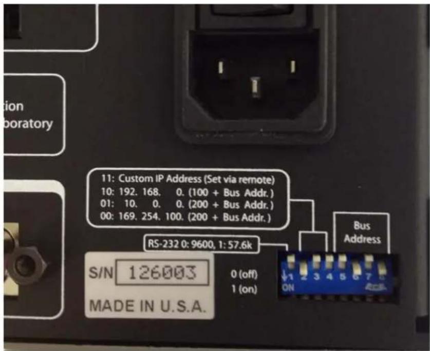
thepolarity:aswitchrepresentsabinary'0'inthe"up"positionor abinary'1'inthe"down"position,andtheleast-significantbitis ontherighthandside.Asettingofup-up-down-up-down,reading
lefttorightonthebusaddressswitches(asshowninFigure1.2), representsabinary00101,correspondingtobusaddress5(Figure1.5).
text_image
11: Custom IP Address (Set via remote) 10: 192. 168. 0. (100 + Bus Addr.) 01: 10. 0. 0. (200 + Bus Addr.) 00: 169. 254. 100. (200 + Bus Addr.) RS-232 0: 9600, 1: 57.6k S/N 126003 MADE IN U.S.A. 0 (off) 1 (on) Bus AddressFigure1.5: RearpanelDIPswitchexample.
Thebusaddressshouldbesettoavaluebetween1and30. Ifallfive switchesareinthe1position, thevalueisforcedto30, not31.
Anychangesmadewillnottakeeffectuntiltheinstrumentispower cycled.
1.2.2Ethernet
TheSX199comesstandardwithanRJ-45networkcommunications portlocatedontherearpanel.TheportmaybeusedtocommunicatewiththeSX199overa10/100Base-Tethernetconnectednetwork orLAN.TheSX199supportsstaticnetworkconfigurationasdeterminedbytherearpanelDIPswitches.Anychangesmadetothe interfaceconfigurationwillnottakeeffectuntiltheunitispower cycled.
TheIPAddress configuration is primarily selected by positions2 and 3 of the larger DIP switch. As with the GPI Baddress selection, a switcheither represents arbitrary '0' in the up position, or binary '1' in the down position. There are four possible waysto arrangethese two switches: 00, 01, 10, and 11. The corresponding configurations are shown in Table 1.1.
| Config.SwitchesIPAddressSubnetMaskGateway | ||
| 11CustomAddressCustomCustom10192.168.0.(100+BusAddress)255.255.255.00.0.0.001172.201.25.(100+BusAddress)255.255.0.00.0.0.00010.0.0.(200 + Bus Address) | 255.0.0.0 | 0.0.0.0 |
Table1.1: IPAddressconfiguration
These switches give a number of possible static IP addresses that may be useful for your SX199, depending on your network environment. As an example, with the two switches set to 10 (down-up) and the (GPIB) Bus Address set to 5, the IP address will be configured as 192.168.0.105, the subnet mask will be 255.255.255.0, and the default gateway will be 0.0.0.0. Using a remote interface, it is also possible to assign and save custom values for these three parameters. Settheconfigurationswitchesto11touseyourcustomvalue.
1.2.3 RS-232
The RS-232 interface connector is a standard 9 pin, type D, female connector configured as a DCE (transmit on pin 3, receive on pin 2). The communication parameters are: 8 Data bits, 1 Stop bit, No Parity, No Hardware Flow Control. All of these parameters are fixed. The baud rate may be set to either 9600 or 57600 via the leftmost switch on the DIP switch block. Any changes made to the interface configuration will not take effect until the unit is powercycled.
1.3Debug port
In addition to the optical ports and the remote interface connections, the SX199 includes an RS-232 "debugging" port on the rear panel. This connection, like the remote RS-232, is a standard 9 pin, type D, female connector configured as a DCE. The baud rate for the debug portmatchesthemainRS-232portsetting.
All data passing through the SX199, whether part of link mode to or from an optical port, or native SX199 commands and queries, is also transmitted out the debug port. This debug stream can be convenient when troubleshooting new user programs or instrument configurations.
Error messages from the SX199 are also transmitted on the debug port.
2RemoteOperation
ThischapterdescribesoperatingtheSX199overtheremoteinterfaces.
InThisChapter
2.1Indexofcommands....2-2
2.2Alphabeticlistofcommands....2-3
2.3Introduction....2-5
2.3.1 Interfaceconfiguration....2-5
2.3.2Buffers....2-5
2.4Ethernet....2-5
2.5Linkmodel....2-6
2.6Commands....2-7
2.6.1 Commandsyntax....2-7
2.6.2 Notation....2-8
2.6.3Examples....2-8
2.6.4Linkcommands ......2–9
2.6.5Interfacecommands .....2-11
2.6.6Statuscommands....2-14
2.7Statusmodel....2-17
2.7.1Statusbyte(SB)....2-18
2.7.2Servicerequestenable(SRE)......2-18
2.7.3 Standardeventstatus(ESR) ......2–18
2.7.4Portstatusevent(PSEV) ......2–19
2.1 Indexofcommands
SymbolDefinition
i,jUnsignedinteger
zLiteraltoken
(?)Requiredforqueries;illegalforsetcommands
varParameteralwaysrequired
{var}Requiredparameterforsetcommands;illegalforqueries
[var]Optionalparameterforbothsetandqueryforms
Link
LINK(?){i}2-9Link
LNKS(?){i}2-9LinkSerial
LNKE(?){i}2-10LinkEthernet
LNKG(?) {i} 2-10 Link GPIB
UNLK 2-10Unlink
SESC(?) {i} 2-10 Set escape character
Interface
*IDN? 2-11Identify
TOKN(?) {z} 2-11 Token Mode
TERM(?) {z} 2-11 Response Termination
*OPC(?) 2-11Operationcomplete
ULOC(?) {i} 2-12 Unlock Ethernet
IPAD(?) i {, j} 2-12 IP Address
NMSK(?) i {, j} 2-12 Netmask
GWAY(?) i {, j} 2 - 13 Default Gateway
MACA? 2-13Ethernethardwareaddress
ENET(?) {z} 2-13 Ethernet speed
SPAR {z} 2-13 Save User Parameters
*RST 2-13Reset
Status
*STB?[i] 2-14Statusbyte
*SRE(?) [i,] {j} 2-14 Service request enable
*ESR?[i] 2-14Standardeventstatus
*ESE(?) [i,] {j} 2-14 Standard event status enable
PSEV?[i] 2-14Portstatusevent
PSEN(?) [i,] {j} 2-14 Port status enable
*CLS 2-15Clearstatus
LEXE? 2-15Lastexecutionerror
LCME? 2-15Lastcommanderror
2.2Alphabeticlistofcommands
★
*CLS2-15Clearstatus
*ESE(?) [i,] {j} 2-14 Standard event status enable
*ESR?[i]2-14Standardeventstatus
*IDN?2-11Identify
*OPC(?)2-11Operationcomplete
*RST2-13Reset
*SRE(?) [i,] {j} 2-14 Service request enable
*STB?[i]2-14Statusbyte
E
ENET(?) {z} 2-13 Ethernet speed
G
GWAY(?) i {, j} 2-13 Default Gateway
|
IPAD(?) i {, j} 2-12 IP Address
L
LCME? 2-15Lastcommanderror
LEXE? 2-15Lastexecutionerror
LINK(?) {i} 2-9 Link
LNKE(?) {i} 2-10 Link Ethernet
LNKG(?) {i} 2-10 Link GPIB
LNKS(?) {i} 2-9 Link Serial
M
MACA? 2 – 13 Ethernet hardware address
N
NMSK(?) i {, j} 2-12 Netmask
P
PSEN(?) [i,] {j} 2-14 Port status enable PSEV?[i] 2-14Portstatusevent
S
SESC(?) {i} 2 - 10 Set escape character SPAR {z} 2 - 13 Save User Parameters
T
TERM(?){z}2-11ResponseTermination
TOKN(?){z}2-11TokenMode
U
ULOC(?)i2-12UnlockEthernet
UNLK2-10Unlink
2.3 Introduction
TheSX199OpticalInterfaceControllerprovidesbuffered,multiplexedcommunicationsbetweenthehostcomputerandupto4instrumentsthroughanopticalfiberinterface.Dataisencodedonthe opticalfiberasasynchronousserialdatausingstandardUARTtimingprotocol,with8databits,noparity,onestopbit,and9600baud. Datapolarityontheopticalportsis:illuminated=startbit=data "0".
The host computer communicates with the SX199 through the host "remote interface", which can be either GPIB, ethernet, or RS-232. All remote interfaces are active and available simultaneously on the SX199.
RemoteoperationoftheSX199istroughasimplecommandlanguagedocumentedinthischapter. Bothsetandqueryformsof mostcommandsaresupported,allowingtheusercompletecontrol ofthecontrollerfromaremotecomputerthroughtheGPIB,RS-232,orethernetinterface.WhiletheSX199hasnodirectinstrumentation itself,itactsasa"transparentlink"tooneofuptofourdownstream instrumentsconnectedthroughtheopticalfiberinterface.
2.3.1Interfaceconfiguration
All three remote interfaces have configuration settings that may need adjusting from the rear panel DIP switch. See section 1.2 on page 1 – 3forconfigurationofthespecificswitchsettings.
2.3.2Buffers
Except during linkmode, the SX199 stores incoming bytes from the remote interfaces in separate 64-byte input buffers. Characters accumulate in the input buffer until a command terminator ( CR , LF , or GPIB-EOI signal) is received, at which point the message is parsed and enqueued for execution. Query responses from the SX199 are buffered in interface-specific 256-byte output queues.
Ifaninputbufferoverflows,thenalldataintheinputbufferare discarded,andanerrorisrecordedintheESRstatusregister.
2.4Ethernet
ToconnecttotheSX199viatheethernetinterface,theusermustfirst configure thenetworkparameters.Onceconnectedtolocalnetwork (orsimpleethernetcrossoverable),establishasocketconnectionto TCP/IPport8888.Sendablanklinetoinitializetheconnection,and thensendtheULOC1commandtounlocktheethernetcommand
processor(seepage2–12).Next,the*IDN?queryshouldbesent. TheSX199shouldreplywiththeresponsestringdescribedonpage2–11.
2.5Linkmodel
TheSX199usesa"link"frameworkforprovidingcommunications betweenahostremoteinterfaceandthedownstreaminstruments connectedbyopticalfiber.Inthislinkmodel,whena"link"is established, a single remote interface is linked to a single optical port: databytesreceivedfromtheremoteinterfacearerelayeddirectlyto theopticalfiberport,andresponesdatareceivedfromtheoptical portarerelayedbacktotheremoteinterface.Whilelinked,front panelindicatorsfortheselectedopticalportandthelinkedremote interfaceareilluminated.
Afterfirstestablishingalink, it may be necessary to initialize the optical port and theremote interface of the fiber-coupled instrument by sending a LF character before beginning remote commanding.
Thehostremoteinterface(s)thatarenotlinkedremainavailablefor regularcommandingtotheSX199. Theseinterface(s)canbeused to reconfigurethelinkstate,ortoquerystatusregistersoftheSX199,or anyotherremotecommanddocumentedinthischapter.Thelinked remoteinterface,however,willnotbeprocessed(parsed)bythe SX199—commandstransmittedtotheSX199viathelinkedremote interfacewillberelayedbyte-for-bytetothelinkedopticalport,and notinterpretedasSX199commands.
The link state can be exited by transmitting an "escape" character from the host computer to the linked remote interface, followed by any other character. Tot transmit the escape character to the linked optical port, you must transmit the escape character twice. After reset, the escape character is the "!" character (character code 33). Se the SESC command (page 2–10) for reprogramming the escape character to another byte.
2.6Commands
Thissectionprovidessyntaxandoperationaldescriptionsforremote commands.
2.6.1 Commandsyntax
The four letter mnemonic (shown in CAPS) in each command sequence specifies the command. Therest of these sequence consists of parameters.
Commandsmaytakeeithersetorqueryform,dependingonwhether the“?”characterfollowsthemnemonic.Setonlycommandsare listed without the “?”, query only commands show the “?” after the mnemonic,andoptionallyquerycommandsaremarkedwitha“(?)”.
Parametersshownin{}and[]arenotalwaysrequired.Parameters in{}arerequiredtosetavalue,andshouldbeomittedforqueries.Parametersin[]areoptionalinbothsetandquerycommands.Parameterslistedwithoutsurroundingcharactersarealwaysrequired.
Donotsend()or{}or[]aspartofthecommand.
Multipleparametersareseparatedby commas. Multiple commands may besentonone command line by separating them with semi-colons (;) solongasthe input buffer does not overflow. Commands are terminated by either CR or LF characters. Null commands and whitespaces are ignored. Execution of the command does not begin until the command terminator is received.
tokens Token parameters (generically shown as z in the command descriptions) can be specified either as a key word or an integer value. Command descriptions list the valid keyword options, with each keyword followed by its corresponding integer value. For example, to set the response terminator to LF, the following twocommands are equivalent:
TERM LF —or— TERM 2
Forqueriesthatreturntokenvalues,thereturnformat(keywordor integer)isspecifiedwiththeTOKNcommand.
2.6.2 Notation
The following tables summarize the notation used in the command descriptions:
SymbolDefinition
i,jUnsignedinteger
zLiteraltoken
(?)Requiredforqueries;illegalforsetcommands
varParameteralwaysrequired
{var}Requiredparameterforsetcommands;illegalforqueries
[var]Optionalparameterforbothsetandqueryforms
2.6.3Examples
Eachcommandisprovidedwithasimpleexampleillustratingits usage.Intheseexamples,alldatasentbythehostcomputertothe SX199 are set as straight teletype font, while responses received by the host computer from the SX199 are set as slanted teletype font.
The usage examples vary with respect to set/query, optional parameters, and token formats. These examples are not exhaustive, and are intended to provide a convenient starting point for user programming.
2.6.4 Link commands
| LinkLINK(?){i} | |
| Setorquerytheopticalportlink. | |
| Setting the LINK i command to a value i between 1 and 4 establishes thelinkstatebetweenopticalportandtheremoteinterfaceonwhich theLINKcommandwasreceivedbytheSX199.Onceexecuted,that remoteinterfacewillnowbe"linked"—subsequentdatareceived fromthehostcomputerontheremoteinterfacewillbetransmitted toopticalporti. | |
| Toterminatealinksessionfromthelinkedremoteinterface,send theescapecharacterfollowedbyanyothercharater.Afterreset,the escapecharacterisinitiallythe"!"character(charactercode33). | |
| ThequeryformLINK?respondswith0ifnolinkispresentlyactive, orwithatwo-digitintegerrp,wherethefirstdigitristhelinked remote interface (1 for RS-232, 2 for GPIB, and 3 for ethernet). The second digit p is the linked optical port, and is a value from 1 to 4. | |
| ThefollowingqueryexampleshowstheresponsewhentheGPIB interfaceislinkedtoopticalport4. | |
| Example: | LINK? |
| 24 | |
| LNKS(?) {i} | Link Serial |
| Set(query)theopticalportlinkstatusforthehostRS-232 (serial)port {toopticalporti}. | |
| Setting LNKS to a value i between 1 and 4 establishes an active link betweentheRS-232(serial)remoteinterfaceandopticalporti. If anyotherportwaspreviouslylinked,itdisconnectsthatlinkinthe process.IfLNKSisreceivedontheRS-232remoteinterface,thisis equivalenttotheLINKcommand. | |
| Setting LNKS 0 disconnects the link state of the RS-232 (serial) remote interface from any optical port. Note if either of the other two remote interfaces is in the active link state, LNKS 0 has no effect. | |
| Example: | LNKS1LinkEthernetLNKE(?) {i} |
| Set(query)theopticalportlinkstatusforthehostethernetport{to opticalporti}. | |
| Setting LNKE to a value i between 1 and 4 establishes an active link between theethernetremote interface and optical porti. If any other port was previously linked, it disconnects that link in the process. If LNKE is received on theethernetremote interface, this is equivalent to the LINK command. | |
| Setting LNKE disconnectstehlinkstate of theethernet remote interface from any optical port. Note if either of the other to remote interfaces is in the active link state, LNKE has no effect. | |
| LNKE1 Example: | |
| LinkGPIBLNKG(?) {i} | |
| Set(query)the optical portlink status for the host GPIB port {to optical porti}. | |
| Setting LNKG to a value i between 1 and 4 establishes an active link between the GPIB remote interface and optical porti. If any other port was previously linked, it disconnects that link in the process. If LNKG is received on the GPIB remote interface, this is equivalent to the LINK command. | |
| Setting LNKG disconnectstehlinkstate of theethernet remote interface from any optical port. Note if either of the other to remote interfaces is in the active link state, LNKG has no effect. | |
| LNKG1 Example: | |
| Unlink UNLK | |
| This set-only command force the SX199 to the unlinked state. | |
| Note that this command can only be received on a currently-unlinked remote interface. Tounlink using the linked remote interface, trans- mit the escape character! followed by any other character. | |
| Example: | UNLK |
| SESC(?) {i} | Set escape character |
| Set (query) the escape character {to character code i}. The valid range for i is 0 ≤ i < 255. The default value is SESC 33 (the “!” character). | |
| Example: | SESC? |
| 33 |
2.6.5 Interface commands
| Identify*IDN?QuerytheSX199identificationstring.Theresponseisformattedas:StanfordResearchSystems, SX199, s/n******, ver#. ##where*****isthe6-digitserialnumber,and#. ##isthefirmware revisionlevel.*IDN?Example:StanfordResearchSystems, SX199, s/n098023, ver1.01 | |
| TokenModeTOKN(?){z}Set (query) the token response mode {to z=(OFF 0, ON 1)}.Tokenresponsemodecontrolstheformattingofresponsemessages generatedbytheSX199toremotequeriesoftoken-typevalues.When TOKNOFF,theSX199respondswiththenumericversionofthetoken quantity. When TOKN ON, the text version is returned.TOKN?Example:ON | |
| TERM(?) {z} | Response TerminationSet (query) the token response mode {to z=(NONE 0, CR 1, LF 2, CRLF3,LFCR4)}.ResponsemessagesgeneratedbytheSX199willbe terminatedby the 0-, 1- or 2-character termination sequence specified by TERM. Note that the TERM command is interface specific. In other words, if TERM LF is received on the RS-232 interface, and then TERM CRLF is received on the ethernet interface, then queries received on the RS-232 interface shall generate response messages terminated with the LFcharacter,whilequeriesreceived ontheethernetinterfaceshall generateresponsemessagesterminatedbytheCRandLF characters. |
| Example: | TERMLF |
| *OPC(?) | OperationcompleteThe set form, *OPC, will set the OPC bit in the Standard Event Status register;thequeryform,*OPC?,willreturnthevalue1.*OPC is useful for pacing streams of remote commands; the *OPC commandwillnotbeprocessed bythecommandexecutionofthe SX199untilallprecedingcommandshavebeenexecuted. |
2-12 RemoteOperation
| *0PC?Example:1 | |
| UnlockEthernetULOC(?){i}Set (query) the ethernet command lockout {to i}.Upon power-up, the SX199 defaults to ULOC 0, which locks out all remotecommandingovertheethernetport.Toenableethernetcontrol, sendthecommandULOC1.Whenfirstconnectingtotheethernetcommandport(port8888),the user'sapplicationprogramshouldbeginbysendingULOC1.The ULOCcommandistheonlycommandthatcanbeprocessedover ethernetwhileULOC0.ULOC1Example: | |
| IPAD(?) i {, j} | IP AddressSet (query) byte i of the “Custom” internet address {to j}.Note that byte 0 is the left-most byte of the address. This address is used when the rear-panel DIP switches are in the “11” (down-down) position.Also note that changes to IPAD are not saved until the SPAR 0 commandisissued. |
| Example: | IPAD?0; IPAD?1; IPAD?2; IPAD?3169;254;46;27 |
| NMSK(?) i {, j} | NetmaskSet (query) byte i of the “Custom” internet network mask {to j}.Notethatbyte0istheleft-mostbyteofthemask. Thisaddressis used when the rear-panel DIP switches are in the “11” (down-down) position.Also note that changes to NMSK are not saved until the SPAR 0 commandisissued. |
| Example: | NMSK1,255; NMSK?0; NMSK?1; NMSK?2; NMSK3255;255;0;0DefaultGatewayGWAY(?)i{,j}Set (query) byte i of the internet default gateway {to j}.Notethatbyte0istheleft-mostbyteoftheaddress.Thisaddressis usedwhentherear-panelDIPswitchesareinthe“11”(down-down) position.Also note that changes to GWAY are not saved until the SPAR 0 commandisissued.GWAY0,172Example: |
| EthernethardwareaddressMACA?Querythelow-levelethernethardwareaddress(MACaddress).This isnotthesameastheIPaddress,andcannotbechangedbytheuser. | |
| Example: | MACA?0019:b303:ffff |
| ENET(?) {z} | Ethernet speedSet (query) the ethernet speed{to z=(AUTO 0,M10 1,M100 2)}.The ethernet speed can be set to 100Base-T (z = M100), 10Base-T (z = M10), or autonegotiate between the two speeds (z = AUTO). |
| Example: | ENET?0 |
| SPAR {z} | Save User ParametersSaveusersettingstonon-volatilememory. Thetokenz should always be 0. This command is needed to record changes to internetaddressbeforepowercycling. |
| Example: | SPAR0 |
| *RST | ResetResettheSX199toitsdefaultconfiguration.The following commands are internally executed upon receipt of the*RSTcommand:UNLK TOKNOFFNote that *RST does not modify the SESC setting, or any of the statusenableregistervalues. |
*RSTExample:
2.6.6Statuscommands
| Statusbyte*STB?[i]ReadstheStatusByteregister[biti].*STB?Example:0 | |
| *SRE(?) [i,] {j} | Service request enableSet (query) the Service Request Enable register [bit i] {to j}.*SRE0, 1Example: |
| Standardeventstatus*ESR?[i]ReadstheStandardEventStatusRegister[biti].Uponexecuting*ESR?,thereturnedbit(s)oftheESRregisterare cleared.*ESR?Example:64 | |
| *ESE(?) [i,] {j} | Standard event status enableSet (query) the Standard Event Status Enable Register [bit i] {to j}.*ESE6, 1Example:ESE?64 |
| PSEV?[i] | PortstatuseventReadsthePortStatusEventRegister[biti].UponexecutingPSEV?,thereturnedbit(s)ofthePSEVregisterare cleared.PSEV?Example:4 |
| PSEN(?) [i,] {j} | Port status enableSet (query) the Port Status Enable Register [bit i] {to j}.PSEN3, 1Example:PSEN?4 |
Clearstatus*CLS
*CLSimmediatelycleartheESRregisterandthePSEVregister.
*CLSExample:
LastexecutionerrorLEXE?
Querythelastexecutionerrorcode.AqueryofLEXE?alwaysclears theerrorcode,soasubsequentLEXE?willreturn0.Validcodesare:
ValueDefinition
0NoexecutionerrorsincelastLEXE?
1Illegalvalue
2Wrongtoken
3Invalidbit
4Queuefull
5Notcompatible
LNKG7; LEXE? ; LEXE? Example:
1;0
Theerror(1, "Illegalvalue,")isbecausetheparametervalue(7)is too large for LNKG. The second read of LEXE? returns 0.
LastcommanderrorLCME?
Querythelastcommanderrorcode.AqueryofLCME?alwaysclears theerrorcode,soasubsequentLCME?willreturn0. Validcodesare:
ValueDefinition
0NoexecutionerrorsincelastLCME?
1Illegalcommand
2Undefinedcommand
3Illegalquery
4Illegalset
5Missingparameter(s)
6Extraparameter(s)
7Nullparameter(s)
8Parameterbufferoverflow
9Badfloating-point
10Badinteger
11Badintegertoken
12Badtokenvalue
13Badhexblock
14Unknowntoken
*IDNExample:
LCME?
4
Theerror(4,"Illegalset")isduetothemissing"?"
2.7Statusmodel
TheSX199statusregistersfollowthehierarchicalIEEE-488.2format.statusregisters AblockdiagramofthestatusregisterarrayisgiveninFigure2.1.

flowchart
graph TD
    A["Standard Event Status"] --> B["ESR ESE"]
    A --> C["SB SRE"]
    A --> D["PSEV PSEN"]
    E["Port Status"] --> F["0"]
    E --> G["1"]
    E --> H["2"]
    E --> I["3"]
    E --> J["4"]
    E --> K["5"]
    E --> L["6"]
    E --> M["7"]
    N["Status Byte"] --> O["0"]
    N --> P["1"]
    N --> Q["2"]
    N --> R["3"]
    N --> S["4"]
    N --> T["5"]
    N --> U["6"]
    N --> V["7"]
    W["Port Status"] --> X["0"]
    W --> Y["1"]
    W --> Z["2"]
    W --> AA["3"]
    W --> AB["4"]
    W --> AC["5"]
    W --> AD["6"]
    W --> AE["7"]
    W --> AF["8"]
    W --> AG["9"]
    W --> AH["10"]
    W --> AI["11"]
    W --> AJ["12"]
    W --> AK["13"]
    W --> AL["14"]
    W --> AM["15"]
    W --> AN["16"]
    W --> AO["17"]
    W --> AP["18"]
    W --> AQ["19"]
    W --> AR["20"]
Figure2.1:StatusModelfortheSX199OpticalInterfaceController
There are three categories of registers in the status model of the controller:
Event Registers: These read-only registers record the occurrence of defined events within the controller. If the event occurs, the correspondingbitissetto1. Uponqueryinganeventregister,any set bits within it are cleared. These are sometimes known as "sticky bits," since once set, a bit can only be cleared by reading its value. Event register names end with SR or EV.
Enable Registers : These read/write registers define a bitwise mask for their corresponding event register. If any bit position is set in an event register while the same bit position is also set in the enable register, then the correspondings summary bit message is set in the status byte. Enable register names end with SE or EN.
StatusByte: Thisread-onlyregisterrepresentsthetopofthestatusmodel, andispopulatedwithsummarybitmessagesandinterface conditionbits.EnabledbitswithintheStatusBytegeneratethe remoteRequestServiceevent.
Atpower-on, allstatusregistersarecleared.
2.7.1 Statusbyte(SB)
TheStatusByteisthetop-levelsummaryoftheSX199statusmodel. WhenenabledbytheServiceRequestEnableregister,abitsetintheStatusBytecausestheMSS(MasterSummaryStatus)bittobeset.
| WeightBitFlag | |
| 10 | PSSB |
| 21 | undef(0) |
| 42 | undef(0) |
| 83 | undef(0) |
| 164 | undef(0) |
| 325 | ESB |
| 646 | MSS |
| 1287 | undef(0) |
PSSB:PortStatusSummaryBit.Indicateswhetheroneormoreofthe enabledeventbitsinthePortStatusEventRegisteristrue.
ESB:EventStatusBit.Indicateswhetheroneormoreoftheenabled eventsintheStandardEventStatusRegisteristrue.
MSS:MasterSummaryStatus.Indicateswhetheroneormoreofthe enabledstatusmessagesintheStatusByteregisteristrue.
Thisregisterisreadwiththe*STB?query.
2.7.2 Servicerequestenable(SRE)
EachbitintheSREcorrespondsone-to-onewithabitintheSBregister,andactsasabitwiseANDoftheSBflagstogenerateMSS.Bit6of theSREisundefined—settingithasnoeffect,andreadingitalways returns0.Thisregisterissetandqueriedwiththe*SRE(?)command.
Atpower-on, thisregisteriscleared.
2.7.3 Standardeventstatus(ESR)
TheStandardEventStatusRegisterconsistsof8eventflags. These eventflagsareall"stickybits"thataretbythecorresponding events, and cleared only by reading or with the *CLS command. Reading a single bit (with the *ESR? i query) clears only Bit i.
WeightBitFlag
10OPC
21INP
42undef(0)
83DDE
164EXE
325CME
646undef(0)
1287undef(0)
OPC:OperationComplete.Setbythe*OPCcommand.
INP:InputOverflow.Indicatesdatainoneoftheremoteinterface inputbuffershasbeenlostduetobufferoverflow.
DDE:Device-DependentError.Indicatesaninternalcommand queueoverflow.
EXE:ExecutionError.Indicates the error in a command that was successfully parsed. Out-of-range parameters are an example.
CME:CommandError.Indicatesacommandparser-detectederror.
2.7.3.1 Standardeventstatusenable(ESE)
TheESEactsasabitwiseANDwiththeESRregistertoproducethe single-bitESBmessageintheStatusByteRegister(SB).Theregister canbesetandqueriedwiththe*ESE(?)command.
Atpower-on, thisregisteriscleared.
2.7.4 Portstatusevent(PSEV)
ThePortStatusEventRegisterconsistsof4eventflags.Thesevent flagsareall"stickybits"thataresetbythecorrespondingevents, andclearedonlybyreadingorwiththe*CLScommand.Readinga single bit (with the PSEV? i query) clears only Bit i.
WeightBitFlag
10Port1
21Port2
42Port3
83Port4
164undef(0)
325undef(0)
646undef(0)
1287undef(0)
The four defined bits in PSEV correspond one-to-new with the four optical ports. Abitissetin PSEV when the corresponding optical port asserts the "statusmessage" by driving a serial "break" signal
ontheopticalport. This is the method available for optical port remote instrument store requests service asynchronously.
2.7.4.1 Portstatuseventenable(PSEN)
ThePSENactsasabitwiseANDwiththePSEVregistertoproduce thesingle-bitPSSBmessageintheStatusByteRegister(SB).The registercanbesetandqueriedwiththePSEN(?)command.
Atpower-on, thisregisteriscleared.