SIM970 - Voltmeter SRS - Free user manual and instructions
Find the device manual for free SIM970 SRS in PDF.

User questions about SIM970 SRS
0 question about this device. Answer the ones you know or ask your own.
Ask a new question about this device
Download the instructions for your Voltmeter in PDF format for free! Find your manual SIM970 - SRS and take your electronic device back in hand. On this page are published all the documents necessary for the use of your device. SIM970 by SRS.
USER MANUAL SIM970 SRS
ThisStanfordResearchSystemsproductiswarrantedagainstdefectsinmaterialsandworkmanshipforaperiodofone(1)yearfromthedateofshipment.
Service
Forwarrantyserviceorrepair, thisproductmustbereturnedtoaStanfordResearchSystems authorizedservicefacility.ContactStanfordResearchSystemsoranauthorizedrepresentative beforereturningthisproductforrepair.
Informationinthisdocumentissubjecttochangewithoutnotice.
Copyright © StanfordResearchSystems, Inc., 2003–2010. Allrightsreserved.
StanfordResearchSystems, Inc.
1290-DReamwoodAvenue
Sunnyvale, CA94089USA
Phone:(408)744-9040• Fax:(408)744-9049
www.thinkSRS.com• e-mail:info@thinkSRS.com
PrintedinU.S.A.Documentnumber9-01559-903
Contents
GeneralInformationiii
SafetyandPreparationforUse......iii
Symbols......iv
Notation......v
Specifications......vi
1GettingStarted1-1
1.1 Introduction to the Instrument......1-2
1.2Front-PanelOperation....1-3
1.3InputProtection....1-4
1.4 Power-On 1-5
1.5RestoringtheDefaultConfiguration...... 1-6
1.6SIMInterface....1-7
2DescriptionofOperation
2-1
2.1 Operating Modes 2-2
2.2Autoranging.... 2-8
2.3 Controlling the Mode and Auto Settings ..... 2-9
2.4 Other Instrument Features 2-10
2.5 Triggering 2-10
3RemoteOperation
3-1
3.1IndexofCommonCommands.... 3-2
3.2 Alphabetic List of Commands 3-4
3.3 Introduction 3-6
3.4 Commands 3-6
3.5 Status Model 3-18
GeneralInformation
TheSIM970QuadDigitalVoltmeter, part of Stanford Research Systems' Small Instrumentation Modules family, consist of four isolated digital voltmeter (DVM) channels. Five and half-digit resolution and overall accuracy are available for inputswithin ±20 volts.
SafetyandPreparationforUse

WARNING
Thefront-panelinputstotheSIM970areisolatedfromtheEarth,the power-line-outletground,themetalchassisofthemodule,andfrom eachother.Nodangerousvoltagesaregeneratedbythemodule. However,ifadangerousvoltageisappliedtoaninput,itmaybe presentontheoutercasingoftheinputcoaxial(BNC)connector,and maycauseinjuryordeath.
Do not exceed ±20 volts to the Earth at the positive (center) terminal of each input connector. Do not exceed ±20 volts to the Earth at the negative (shield) terminal of each input connector.
Donotinstallsubstitutepartsorperformunauthorizedmodifications tothisinstrument.
TheSIM970isadouble-widemodule designed to be used inside the SIM900Mainframe. Donotturnonthepower to themainframe or apply voltage input to the module until the module is completely inserted into themainframe and locked in place.
SymbolsyoumayFindonSRSProducts
| Symbol Description | |
 | Alternating current |
 | Caution - risk of electric shock |
 | Frame or chassis terminal |
 | Caution - refer to accompanying documents |
 | Earth (ground) terminal |
 | Battery |
 | Fuse |
| On (supply) | |
| Off (supply) | |
Notation

WARNING

CAUTION
The following notation will be used throughout this manual:
A warning mean that injury or death is possible if the instructions are not obeyed.
Acautionmeansthatdamagetotheinstrumentorotherequipment is possible.
- Front-panelbuttonsaresetas[Button]; [Adjust]!shorthandfor"[Adjust]&[Adjust]".
- Front-panelindicatorsaresetasOverload.
• SignalnamesaresetasBUSY.
• SignallevelsaresetasHIGH. - Remotecommandnamesaresetas*IDN?.
- LiteraltextotherthancommandnamesissetasOFF.
• SpecialASCIIcharactersaresetas⟨CR⟩.
Specifications
Ranges, Resolution, and Noise
Underfront-paneloperation, the SIM970 has four voltageranges. See Table 2.1 formoredetails.
| Range | Maximuminput voltage | Resolution[1] | Noise, countsrms[2,3] |
| 1 | ±19.9999 V | 100 μV | 1.5 |
| 2 | ±1.99999 V | 10 μV | 0.8 |
| 3 | ±999.99 mV | 10 μV | 0.8 |
| 4 | ±199.999 mV | 1 μV | 1.0 |
Conditions:
[1]7 ^1/2 digits, or 24 bits, of resolution are available through the remote interface.
[2]Onecountisaunitchangeintheleast-significantdigit. Eachfront-panel display of the SIM970 has a capacity of ±199999 counts.
[3] Measured over 360 consecutive readings.
Accuracy
Accuracyspecifications[4,5]arethesameforallfourchannels.The fourchannelshaveisolatedcircuitry,sonochannel-matchingspecificationsexist.
In ±(reading × 10 ^-6 + counts)[2]
| Range | 24hours, (23 ± 1)C | 90days, (23 ± 5)C | 1year, (23 ± 5)C |
| 1 | 10 + 2 | 50 + 2 | 80 + 2 |
| 2 | 2 + 2 | 50 + 2 | 80 + 2 |
| 3 | 2 + 2 | 50 + 2 | 80 + 2 |
| 4 | 2 + 4 | 50 + 6 | 80 + 6 |
(Relativetocalibrationstandards[7])
Transfer accuracy: (24-hour count error)/2 (typ.) [6]
Conditions:
[4]InsideafullyoccupiedSIM900Mainframe; followinga2-hour warmup.
[5] Specifications apply to Ranges 1 through 4 only, locally triggered (Table 2.1).
[6] Within 10 minutes and ± 0.5^ , within ± 10% of the initial value, on a fixedrange, input voltage between 10% and 100% of the maximum for therange.
[7] The absolute accuracy of the SRS factory calibration standard with respect to the United States NIST is 6 × 10^-6 of thereading.
MeasuringCharacteristics
| AutoranginglimitsRange11.90000V | MinTyp | pMax | Units | ||
| InputResistance[8]9.910.010.1MΩ | Range2.9 | 50001.999 | 99V | ||
| Range319 | 0.00999.99mV | ||||
| Range419 | 9.999mV | ||||
| 3GΩ | |||||
| Biascurrent[9]1 | pA | ||||
| Terminals | IsolatedBNC[10] | ||||
| Protection,centertoshield±60 | V | ||||
| Protection,shieldtoEarth | ±200 | V | |||
| Trigger | Source | Local,external,orremote | |||
| Externalinput | RearBNC;TTL;activeLOW | ||||
| Latency | 480 | μs | |||
| BUSYoutput | RearBNC;TTL;activeHIGH | ||||
| BUSYimpedance | 50 | Ω | |||
| Measurement | Method2 | 4-bit,Delta-SigmaA/Dconverter | |||
| A/Dlinearity | Correctedbyfirmware[11] | ||||
| Normal-moderejection[12] | 90 | dB | |||
| Common-moderejection,DC[13] | 125 | dB | |||
| Output | Update frequency, 50 Hz FPLC [5] | 3.0 | Hz | ||
| Update frequency, 60 Hz FPLC [5] | 3.6 | Hz | |||
| Settlingtime,Ranges1-3[5,14]1 | s | ||||
| Settlingtime,Range4[5,14] | 10 | s | |||
| Displays | RednumericLED,0.30" | ||||
| GreenLED,rangeandautorange | |||||
| Operating | Temperature[15] | 0 | 40 | °C | |
| Power | +5 | VDC | |||
| Supplycurrent | 480 | mA | |||
| Conditions:[8] Input resistance is 10MΩ for Ranges 1 through 4. Operating modes with >3GΩ input resistance exist (Table 2.1).[9] At 23°C.[10] Amphenol 31-10-4052 or similar.[11] Included in the accuracy specifications.[12] At power-line frequency (FPLC): 59 Hz to 61 Hz or 49 Hz to 51 Hz.[13] For 1 kΩ unbalance in the shield.[14] To within 3 counts of the final reading, on a fixed range, for an input voltage step of 50% of the maximum voltage for the range, for 0Ω source impedance.[15] Non-condensing. | |||||
GeneralCharacteristics
Numberofchannels4
InterfaceSerial(RS-232)throughSIMinterface
ConnectorsBNC(4front[10],2rear);DB-15(male)SIMinterface
Weight2.3lbs
Dimensions3.0 "W× 3.6 H× 7.0 D
1GettingStarted
Thischaptergivesyouthenecessaryinformationtogetstarted quicklywithyourSIM970QuadDigitalVoltmeter.
InThisChapter
1.1 Introduction to the Instrument......1-2
1.1.1Frontpanel....1-2
1.1.2 Rearpanel....1-3
1.2Front-PanelOperation....1-3
1.3InputProtection....1-4
1.4Power-On 1-5
1.5RestoringtheDefaultConfiguration......1-6
1.6SIMInterface ....1-7
1.6.1SIMinterfaceconnector .....1-7
1.6.2 Directinterfacing......1-7
1.1 Introduction to the Instrument
TheSIM970QuadDigitalVoltmeterisdesignedtomakeprecision low-frequencyvoltagemeasurementswithexcellentlong-termaccuracy.Thefourchannelsaregalvanicallyisolatedfromoneanother andfromtheEarth(chassisground).Autocalibrationisperformedchassisground witheveryreadingbysequentiallymeasuringnotonlytheinput voltage,butalsothegroundvoltageandafixedmid-scalevoltage againstacalibratedinternalreference.Thisautocalibrationroutine virtuallyeliminatesoffsetsandscaleerrors.
ComputeraccessthroughtheSIM900Mainframe(RS-232orGPIB) permitsinputvoltageloggingwith24bitofresolution.Thisre-remoteinterface moteinterfaceallowstheusertoexercisedetailedcontroloverthe instrument'ssettings.
Anexternaltriggerinputallowssynchronizationofvoltagereadings onallfourchannelsforapplicationsrequiringcoincidentalreadings. The same functionality can also be achieved through the remote interface.
1.1.1 Frontpanel

text_image
SRS SIM970 Quad DVM RANGE 1 • 0.003 2 - 0.002 3 •18.7499 4 - 0.090 1 2 3 4 Shields float independently, 20 V max Hold for autorange 10 MΩFigure1.1:TheSIM970frontpanel.
text_image
SIM970 QUAD VOLTMETER TRIGGER IN BUSY OUT S/N ✓SRS MADE IN U.S.A.Figure1.2:TheSIM970rearpanel.
1.1.2 Rearpanel
For a description of therear-panel connectors and triggered operation, see Section 2.5.
1.2Front-PanelOperation
EachchanneloftheSIM970measuresavoltageappliedbetweentheBNC center(inner)terminalofafront-panelcoaxial(BNC)connectorandcenterterminal theshield(outer)terminaloftheconnector.Thecenterterminalisshieldterminal thepositiveinput,whereastheshieldisthenegativeinput.
Youcanonlyreachspecificmodesofoperation,whichareRanges1 through4,Table2.1,fromthefrontpanel. Whentheinstrument powersup,autoranging(Section2.2)isturnedon.Whenautorangingison,thecurrentrangeisdeterminedbythemagnitudeofthe input voltage. The automatically selected range will generally be the onethatwillaccommodatetheinputvoltagewithoutoverloading theinputstageoftheinstrument,andwillproduceadisplayreadingwiththehighestpossibleresolution. Whenautorangingison, shortfront-panelbuttonpressesdonothing(exceptasnotedbelow foroperationfromtheremoteinterface).
Inordertoturnautorangingoff,holdthefront-panelbuttonfora
specificchannelformorethan1.5seconds.TheAutoannunciator willturnoff.Afterautorangingis0FF,shortbuttonpresseswill switchbetweenrangesinthesequenceRange1,Range2,Range3,Range4,andbacktoRange1,startingfromthecurrentrange.
Toturnautorangingbackon, hold the button form more than 1.5 seconds. Autowillturnon.
Theremoteinterfaceallowstheusertoexercisespecificcontrolover theoperationoftheSIM970.If,fromtheremoteinterface,theinstrumenthadbeenputintoanoperatingmodethatisnotoneofRanges1 through4(seeSection2.1foradescriptionofoperatingmodes),a front-panelbuttonpresswilltaketheSIM970intooneofRanges1 through4.Rangeclosesttotheremotelyselectedoperatingmode willbechosen.SeeSection2.3.2formoredetails.
The preceding description off front-panel buttons behavior also app- pliesto EXTERNAL triggering in addition to LOCAL triggering. See Section2.5.2 for discussion of externally triggered behavior.
1.3 InputProtection
EachinputtotheSIM970,i.e. thevoltagedifferencebetween the centerterminalofeachfrontcoaxialconnectorandtheconnector's shieldterminal, shouldnotexceed±20Vatallltimes.Whilethis voltageisexceeded, theinstrumentisnotguaranteedtoperform toitsspecifications. Iftheabsolutemagnitudeoftheinputvoltage exceeds30VwiththeinputattenuatorON(Section2.1.2), or3.0V forinputattenuatorOFFForOUT,aninput-protectioncircuitwillbe activated(tripped), disconnectingtheinputvoltagefromtherest of the SIM970's circuitry. If this happens, the following message is displayedonthefrontpanel:
tr, P
If the protection circuit is activated, there will be on new voltage readings available through the remote interface.
In order to clear the protection circuit, push the front-panel button for the tripped channel once. If the overload condition nolonger exists, the protection circuit will turn off. The instrument will automatically attempt to clear the trip after the overload condition has occurred, but will do so only once. The trip can also be cleared from theremote interface by issuing the command TRIP.
Whileachannelistripped, theSIM970issafeandguaranteedto performtospecificationsaftertheoverloadconditionceases. The
magnitudeoftheinputvoltagemustneverexceed±60Vinorderfor theSIM970tobesafeandreturntoitsspecifiedperformance.
Theshieldterminalofeachfront-panelcoaxialconnectorisnotinsulated, andispotentiallyexposedtotheuser. Applyingdangerousvoltagestothis terminalisunsafe, and may cause injury or death.
Although the input to the SIM970 are galvanically isolated from the Earth (i.e. the chassis ground), it is not recommended to exceed ± 20V between the center input terminal and the Earth, or between the shield terminal and the Earth. The instrument is not guaranteed to perform to specifications while these values are exceeded. The SIM970 is guaranteed to perform to these specifications after the overload condition between an input terminal and the Earth ceases if none of the input terminal severe exceed ± 200V , relativeto the Earth.
1.4 Power-On
Upon power-on, the instrument performs a self-test. A message is displayed on the front panel during this time:
5t8r
t in 9
UP
AllofthegreenannunciatorLEDssubsequentlyturnon. Attheend ofthetest,theLEDsturnoffandtheinstrumentstartstakingvoltage readings.
The instrument does not save operation-related settings. The only non-volatile setting that a reretained while the instrument is not powered are calibration values and the power line frequency: 60Hz or 50Hz. The latter equals the principal rejection frequency of an internal filter.
The power-on configuration of theremote interface is detailed in Section 3.3.1.
1.5RestoringtheDefaultConfiguration
ThedefaultconfigurationoftheSIM970isRange1onallfourchannelswithautorangingon(moreprecisely,autorangingsettoALL;see Section2.2),withLOCALtriggering.Itisthepower-onconfiguration. Torestoreit,turntheSIM900Mainframepoweroffandthenon.
Thesameconfigurationcanalsobereachedfromtheremoteinterface byissuingthe*RSTcommand.
1.6SIMInterface
The primary connection to the SIM970 Quad Digital Voltmeter is the rear-panel DB-15 SIM interface connector. Typically, the SIM970 is mated to a SIM900 Mainframe viathis connection, either through one of the internal mainframeslots, or theremotecable interface.
ItisalsopossibletooperatetheSIM970directly, without using the SIM900Mainframe. Thissectionprovidesdetailsontheinterface.
1.6.1 SIMinterfaceconnector
TheDB-15SIMinterfaceconnectorcarriesallthepowerandcommunicationlinestotheinstrument.Theconnectorsignalsarespecified inTable1.1.
| Pin | SignalSrc | DestDescription | Direction |
| 1 | SIGNAL_GND | MF SIM | Ground reference for signal |
| 2 | -STATUS | SIM MF | Status/service request (GND=asserted, +5 V=idle) |
| 3 | RTS | MF SIM | HW Handshake (unused in SIM970) |
| 4 | CTS | SIM MF | HW Handshake (unused in SIM970) |
| 5 | -REF_10MHZ | MF SIM | 10 MHz reference (optional connection) |
| 6 | -5V | MF SIM | Power supply (No connection in SIM970) |
| 7 | -15V | MF SIM | Power supply (No connection in SIM970) |
| 8 | PSRTN | MF SIM | Powersupplyreturn |
| 9 | CHASSISGND | Chassisground | |
| 10 | TXD | MF SIM | Async data (start bit="0" = +5 V; "1" = GND) |
| 11 | RXD | SIM MF | Async data (start bit="0" = +5 V; "1" = GND) |
| 12 | +REF_10MHZ | MF SIM | 10 MHz reference (optional connection) |
| 13 | +5V | MF SIM | Power supply |
| 14 | +15V | MF SIM | Power supply (No connection in SIM970) |
| 15 | +24V | MF SIM | Power supply (No connection in SIM970) |
Table1.1:SIMinterfaceconnectorpinassignments,DB-15.
1.6.2 Directinterfacing
TheSIM970isintendedforoperationintheSIM900Mainframe, but usersmaywishtodirectlyinterfacethemoduletotheirownsystems withouttheuseofadditionalhardware.
ThematingconnectorneededisastandardDB-15receptacle,suchas Amppartnumber747909-2(orequivalent).Aclean,well-regulated supply voltage of +5.0V DC must be provided, following the pinout specified in Table 1.1. Ground must be provided on Pin 8, with chassisgroundonPin9. The-STATUSsignalmaybemonitored onPin2foralow-goingTTL-compatibleoutputindicatingastatus message.SeeSection3.5forthedescriptionofstatusmessages.

CAUTION
TheSIM970hasnointernalprotectionagainstreversepolarityorovervoltage on the +5 V power-supply pin. A supply voltage above 5.5 V is likely todamagetheinstrument.
1.6.2.1 Directinterfacecabling
If the user intend stodirectly wire the SIM970 independent of the SIM900 Mainframe, communication is usually possible by directly connecting the appropriate interfacelines from the SIM970 DB-15 plug to the RS-232 serial port of a personal computer. ^1 Connect RXD from the SIM970 directly to RD on the PC, TXD directly to TD, and similarly RTS→RT Sand CTS→CTS. In other words, anull-modem-styleable is not needed.
TointerfacedirectlytotheDB-9male(DTE)RS-232porttypically foundoncontemporarypersonalcomputers,acablemustbemade withafemaleDB-15sockettomatewiththeSIM970,andafemale DB-9sockettomatewiththePC'sserialport.Separateleadsfrom theDB-15needtogotothepowersupply,makingwhatissometimes knowasa"hydra"cable.ThepinconnectionsaregiveninTable1.2.
DB-15/FtoSIM970Name
| DB-9/F | ||
| 10←→ | 3 | TxD |
| 11←→ | 2 | RxD |
| 5 | ComputerGround | |
| toPowerSupply | ||
| 13←→ | +5 V DC | |
| 8,9←→ | Ground (Supply return current) | |
Table1.2:SIM970directinterfacecablepinassignments.
1.6.2.2 Serialsettings
The initial serial port settings at power-on are: baud rate 9600, 8 bits, n parity, 1 stop bit, and no flow control. These may be changed with the BAUD or PARI commands.
ThemaximumstandardbaudratethattheSIM970supportsis38400. Theminimumbaudrateis110. Above38400, theSIM970canbe settothefollowing(non-RS-232-standard)baudrates:62500,78125, 104167,156250. Notethattheseratesaretypicallynotaccessibleon
astandardPCRS-232port, but can be used between the SIM970 and the SIM900 Mainframe.
2DescriptionofOperation
TousethewholespectrumofSIM970'scapabilities,oneneedsto understandtheinstrument'soperatingmodes.Ranges1,2,3,and4, accessiblefromthefrontpanel,areonlyfouroftheoperatingmodes availabletotheinstrument'suser.
InThisChapter
2.1 Operating Modes 2-2
2.1.1 Scale 2-2
2.1.2 Input attenuator 2-3
2.1.3 Autocalibration 2-4
2.1.4 Digital filter 2-6
2.2 Autoranging 2-8
2.3 Controlling the Mode and Auto Settings ..... 2-9
2.3.1 Remote-interface control 2-9
2.3.2 Front-panel operation 2-9
2.3.3 Illegal modes 2-9
2.4 Other Instrument Features 2-10
2.4.1 Front-panel lockout....2-10
2.4.2 Display blanking and messages ..... 2-10
2.5 Triggering 2-10
2.5.1 Local triggering 2-10
2.5.2 External triggering 2-11
2.5.3 Remote triggering 2-13
2.1 OperatingModes
AnoperatingmodeoftheSIM970isacombinationofsettingsforthe scale,theinputattenuator,theautocalibration,andthedigitalfilter. Table2.1summarizestheavailablemodes.
| Scale | |||||
| 20V2V100 | 0mV200mV | ||||
| Attenuator OFF: | Autocalibration NONE | Illegal | Legal | Legal | Legal |
| Autocalibration GND | Illegal | Range 2 | Range 3 | Range 4 | |
| Autocalibration GNDREF3 | Illegal | Illegal | Illegal | Illegal | |
| Autocalibration GNDREF4 | Illegal | Illegal | Illegal | Illegal | |
| Attenuator ON: | Autocalibration NONE | Legal | Legal | Legal | Legal |
| AutocalibrationGND | Legal | Legal | Legal | Legal | |
| Autocalibration GNDREF3 | Legal | Legal | Legal | Legal | |
| Autocalibration GNDREF4 | Range 1 | Legal | Legal | Legal | |
| Attenuator OUT: | Autocalibration NONE | Illegal | Legal | Legal | Legal |
| Autocalibration GND | Illegal | Legal | Legal | Legal | |
| Autocalibration GNDREF3 | Illegal | Illegal | Illegal | Illegal | |
| Autocalibration GNDREF4 | Illegal | Illegal | Illegal | Illegal | |
ForLOCALtriggering
Table2.1: OperatingmodesoftheSIM970.
For all legal modesshown, the digital filter may be either enabled or disabled. For Ranges1 through 4, digital filter settings are:
| Range | Digitalfilter |
| 1 | OFF |
| 2 | OFF |
| 3 | OFF |
| 4 | ON |
Ranges1through4aretheonlyoperatingmodesaccessiblethrough thefrontpanel.Amuchrichervarietyofmodesareavailablethrough the remote interface. The next Section, "Remote Operation", discussestecommandsnecessarytoputsomeorallofthechannelsof aSIM970intoagivenmode. ThesecommandsarealsobrieflydiscussedinSections2.1.1through2.1.4andSection2.2,whichdescribe theaspectsofoperationthesesettingsaffect.
2.1.1 Scale
The scale setting for a given channel is the position of the decimal pointonthefront-paneldisplayforthischannel.
ScalesettingFront-paneldisplayformat
20V±19.9999V
2V±1.99999V
1000mV± 999.99mV
200mV±199.999mV
Thescalesettingforachannelisrelatedtotherangethechannelmay beon,butthetwotermsarenotequivalent.Arangeisanoperating
mode and consists of other settings in addition to the scale setting. For Ranges 1 through 4, accessible from the front panel, there is a one-to-one correspondence between the range and the scale. However, with the help of the remote interface, the scale for a given mode can be set to every scale in Table 2.1 that is allowed. In other words, the position of the decimal point on the front-panel display does not uniquely determine the input attenuator, the autocalibration, and the digital filter settings if the remote interface is utilized.
Tochangethescalefromtheremoteinterface,issuetheSCALcommand.
If the reading overloads the maximum value that is possible to display onagivenscale, the front-panel display format can change to accommodate the higher reading. If such accommodation is not possible, the following is displayed:
$$ ^ {+} o 1. \quad - \text {or} - \quad - o 1. $$
2.1.2 Input attenuator
The internal analog-to-digital converter of the SIM970 can only sample a voltage between -2.5 and +2.5 volts. In order to measure higher voltages, the input signal must be attenuated inside the SIM970. The input attenuator is a 1:10 voltage divider that can be inserted into the signalpath:
The input attenuator can be ON, in which case the voltage sampled bytheconverteris 110 th of the input voltage; it can be OFF, in which casetheinputvoltageissampleddirectly; anditcanbeOUT, in which case the voltage is also sampled directly and the resistors that comprisetheattenuatoraredisconnectedfromtheinputsignal. For the attenuator OFF and for the attenuator ON, the input resistance of a channel is equal to 10 MΩ. For the attenuator OUT, the resistance exceeds3GΩ.
To change the input attenuator setting from the remote interface, use theDVDRcommand.

text_image
5 V Ref Center 10 M Shield 9 M 1 M Internal Ground ×1 A/D ConverterFigure2.1:Simplifiedschematicoftheinputstagecircuitof theSIM970.
Notallscaleandautocalibrationsettingsarecompatiblewithinputattenuator OFF or OUT. See Section 2.3.3, "Illegal Modes", for more details.
Theformatofthedataavailablethroughtheremoteinterfaceis uniquelydeterminedbytheattenuatorsetting. Thatis,thesettings forthescaleandtheautocalibrationdonot affectthepositionof thedecimalpointinthedatathattheSIM970suppliesthroughthe remoteinterface.
InputattenuatorsettingRemote-interfacedataformat
OFF*Y.XXXXXXX
ON*YX.XXXXXX
OUT*Y.XXXXXXX
*iseithertheminuscharacter("−")oristhespace(""); Yisthecharacter"0","1",or"2"; Xisoneofthecharacters"0"through"9".
2.1.3 Autocalibration
Autocalibrationcorrectsthevoltagereadingfortwokindsoferrors: offset error an offset error and a gain error. The offset errorresults in a constant offsettermaddedtothetruevalueoftheinputvoltage:
(voltage read by the instrument) = (real voltage) + (offset), where (offset) ≠ 0.
gain error The gain errorresults in the voltage reading multiplied by some fac-
tor, compared to the true value:
(voltage read by the instrument) = (real voltage) · (gain), where (gain) ≠ 1.
Mostofthegainererroriscausedbyresistancedriftintheinputattenuator.Someofitisduetogainerrorsinthecircuitrythatfollowsthe inputattenuator,andtoerrorsintheconverter.
Fourautocalibrationregimesarepossible.
AutocalibrationErrorcorrectedHowoftenForothersettings
| NONEOffsetOnceEverycombinationGainOnceAttenuatorONGainNeverAttenuatorOFFForOUT | ||
| GND | OffsetContinuouslyEverycombinationGainOnceAttenuatorONGainNeverAttenuatorOFFForOUT | |
| GNDREF3 | OffsetGainContinuouslyEverycombination | ContinuouslyEvery combination |
| GNDREF4 | OffsetGainContinuouslyEverycombination | ContinuouslyEvery combination |
Autocalibration is performed by the instrument by taking alternating reading of the input voltage, the internal ground, and the internal reference; the ground and reference readings are taken as these voltages pass through the same signal path as the input voltage. Therefore, it is possible to calibrate the input attenuator and subsequent circuitry by comparing the attenuated reference signal with the original.
The sequence of readings for each of the autocalibration regimes is as follows:
AutocalibrationSequenceofreadings
| NONEInput | |
| GND | Input,Ground |
| GNDREF3 | Input,Reference,Ground |
| GNDREF4 | Input,Reference,Input,Ground |
Table2.2: AutocalibrationreadingsequencesfortheSIM970.
After each complete sequence of readings, the front-panel displays are updated with the new value of the input voltage, corrected for the offset and (if available) gain errors, and the new value of the input voltage becomes available to the remote interface. An exception to thisruleistheregimeGNDREF4,inwhichthenewcorrectedvalueis
shownonthedisplaysandisavailabletotheremoteinterfaceafteraReferencereadingistaken,andafteraGroundreadingistaken.
Forerrorscorrected"once",areadingoftheinternalgroundand/or referenceistakenatthetimethemodeswitchestothepresentmode. Thisreadingisusedtocorrectallsubsequentinputvoltagereadings.
ForLOCALtriggering ^1 , theinternalsamplingfrequencyoftheinstrumentisfixedat7.2Hzifthepower-linefrequency(FPLC)is60Hz, andat6.0HzifFPLCis50Hz. Therefore, thefrequencyatwhichcorrectedvoltagereadingsaredisplayedonthefrontpanelandareavailabletotheremoteinterfacedependsontheautocalibrationregime asfollows:
| FPLC(Hz) | ||
| Autocalibration6050 | ||
| NONE7.26.0readings/s | ||
| GND3.63.0readings/s | ||
| GNDREF32.42.0readings/s | ||
| GNDREF43.63.0readings/s | ||
ThedisplayupdatefrequencyforRanges1through4isthesame, 3.6readingspersecondifFPLCis60Hzand3.0readingspersecond ifFPLCis50Hz.
Inordertochangetheautocalibrationregimefromtheremoteinterface,usetheCHOPcommand.
Formaximumaccuracy, chooseautocalibrationregimeGNDiftheinput attenuator is OFF or OUT, and the regime GNDREF3 or GNDREF4 if the attenuator is ON. Choosing autocalibration GND or NONE for attenuatorONresultsinasomewhatdecreasedreadingnoise, attheexpense of anincreasedreadingdrift.
2.1.4 Digitalfilter
The digital filter produces a running exponential average of the results of input voltage readings. The acceptable settings for the filter are ON and OFF. Foreach legal combination of the scale, the attenuator, and the autocalibration settings, it is legal to have the filter ON and it is legal to have the filter OFF. Range 4 has the filter ON, whereas Ranges1 through 3 turn the filter OFF. ^2
The input to the filter is input voltage readings corrected for the offset error and the gain error. Numerically, the filter is a simple IIR (infinite-impulse response) algorithm with a time constant
of8.0readings.Thistimeconstantequals2.22/2.67secondsfor FPLC = 60 Hz/50 Hz if the autocalibration regime is GND or GNDREF4; thetimeconstantis1.11/1.33secondsiftheautocalibrationisNONE. ThesetimevaluesareonlyvalidforLOCALtriggeringwithitsfixed samplerate.
Turning the filter ON reduce the reading-to-reading noise. The filter also increases the instrument's settling time. The filter is temporarily deactivated if there is a large change in input voltage, so to improve the settling characteristic.
Inordertochangetedigitalfiltersettingfromtheremoteinterface, issuetheFLTRcommand.
Inadditiontotheoperatingmode,thebehavioroftheinstrumentis determinedbytheautorangingsettings;thefront-panellockoutand thedisplayblankinganddisplaymessagingoptions;andthetrigger mode.
2.2 Autoranging
Withfront-paneloperation, autoranging can be on or off. If the autoranging is 0N, them magnitude of the input voltage determined the current range for a given channel (one of Ranges1 through 4 in Table 2.1). The SIM970 under-andover-ranges according to the thresholds specifications on Page vii.
autoranging bits
Undertheremoteinterface, the instrument'susercanachieveafiner degree of control over the autoranging behavior. There are four auto bits, set by the command AUTO:
WeightBitToken Meaning
| 1 | 0 | SCALE | Input voltage determines the scale |
| 2 | 1 | DIVIDER | currentscaleddeterminestheinputattenuatorsetting |
| 4 | 2 | CHOP | Current scale determines the autocalibration regime |
| 8 | 3 | FILTER | Current scale determines the digital filter setting |
One or several bits can be set by AUTO. For example, the behavior of the instrument after issuing AUTO 1, 5 will be as follows: For Channel 1, the input voltage will set the scale, which, in turn, will set theautocalibrationregimetotheonethatcorrespondstotherange forthecurrentscaleinTable2.1.However,thecompleteoperating modewillnotbesettothisrange. Inthisexample,theposition ofthedecimalpointonthedisplayofChannel1andthechannel's autocalibrationregimewillchangewiththemagnitudeoftheinput voltagebutneithertheinputattenuatornorthedigitalfiltersettings will. If, further in this example, the input attenuator for Channel 1 has been set to ON and the digital filter set to OFF, the channel's operating modewillrespondinthefollowingwaytoanincreaseintheinput voltage:
| Inputvoltage | Scale | Attenuator | AutocalibrationFilter | |
| 0 mV to +199.999 mV | 200 mV | ON | GND | OFF |
| +200.00 mV to +999.99 mV | 1000 mV | ON | GND | OFF |
| +1.00000 V to +1.99999 V | 2 V | ON | GND | OFF |
| +2.0000 V to +19.9999 V | 20 V | ON | GNDREF4 | OFF |
Unlike with other commands, the behavior of AUTO is different with number arguments and with tokens. See AUTO for more details.
Underfront-paneloperation,alloftheautobitsareofforallof
themareon.Toturnallthebitsofffromtheremoteinterface,issue AUTO n,0 or AUTO n,0FF, where n is the channel number. To turn all of them on, issue AUTO n, 15 or AUTO n, ALL.
Thefront-panelAutoLEDannunciatorforagivenchannelisactive ifAUTOisnot@forthechannel.
2.3ControllingtheModeandAutoSettings
2.3.1 Remote-interfacecontrol
Thescale, input attenuator, autocalibration, and digital filters settings foreach channel can be controlled independently from theremote interface. When issuing the respective commands, the users should be aware of illegal modes (Table 2.1 and Section 2.3.3).
InordertogeteverychanneloftheinstrumentintooneofRanges1 through 4 while under remote-interface control, issue the commandLOCL.Theoperatingmodeforeachchannelwillchangeto therangeappropriateforthechannel'scurrentlyselectedscale(Table2.1). Ifoneorseveraloftheautobitsforachannelwereon,all oftheautobitsforthischannelwillturnon;otherwiseAUTOforthe channelwillbeOFF.
Alternatively, afront-panelbutton push will return the instrument into one of the Ranges. Seethenextsection.
2.3.2 Front-paneloperation
Ifthefront-panelbuttonforachannelispushedwhiletheSIM970is underremotecontrol,theinstrumentwillreturneachchannelinto oneoftheRangesofTable2.1(Table2.3fornon-localtriggering).
This is done by turning all of the AUTO bits for the channel ON if oneorseveralofthemwereon,andleavingthem0FFiftheywere0.
Autorangingwillsubsequentlyselecttheappropriaterange.
2.3.3Illegalmodes
Having control over separate components of the operating mode makes it possible to request an illegal mode (Table 2.1, Table 2.3 for non-local triggering). Illegal modes are accepted via forcing theinputattenuatorsettingto0Nandleavingtherestoftheproposedsettingsintact.ADevice-DependentErrorwillbeissuedwithaDDEILLEGALMODEreturncode(seethecommandLDDE?formore details).
2.4 Other Instrument Features
2.4.1 Front-panellockout
The command FRNT makes it possible to enable order disable the response of the instrument to front-pane events. With FRNTOFF for a particular channel, front-panel button pushes forthatch channel have no effect—FRNT ON must be issued to regain front-panel control.
2.4.2 Displayblanking and messages
Itispossibletodisablethefront-paneldisplayforoneorallchannels. Updatestothechannel'sdisplayandallmultiplexedelectrical activityattheseven-segmentdigitswillstop, and thedisplayswill turndark. UsethecommandDISXtoturndisplaysonandoff.
Aftertheupdatestothedisplayhavebeenturnedoff,itispossibletopaintalphanumericmessagesonthedisplay.Seethe commandMESGformoreinformation. Iftheupdateshavenot been turned off by DISX n,0FF (n is channel number) prior to issuingMESG,themessagewillonlystayonthedisplayforonedisplay cycle;afractionofasecondunderlocaltriggering,butpossibly manysecondsforEXTERNALorREMOTEtriggering.
2.5Triggering
trigger A trigger is an event that signals the SIM970 to take one or several voltage readings. The SIM970 has three trigger modes: LOCAL, EXTERNAL, and REMOTE. Tochangethemode, issue the TMOD command.
For all legal modesshownin Table2.3, the digital filter may be either enabled or disabled. For Ranges1 through 4, digital filter settings are:
| Range | Digitalfilter |
| 1 | OFF |
| 2 | OFF |
| 3 | OFF |
| 4 | OFF |
2.5.1 Localtriggering
Inthelocallytriggeredmode, theinstrumenttakescontinuousreadings. TheBUSYoutputisalwaysHIGH. Althoughthefourchannels take readings synchronously, there is no alignment between the samplesoftheinputvoltage. Thatis, eachofthefourchannelscanbe ineachofthelegalautocalibrationsettings: when, e.g., Channel1 istakingareadingoftheinputvoltage, Channel2 canbetakinga
| Scale | |||||
| 20V2V100 | 0mV200mV | ||||
| Attenuator OFF: | Autocalibration NONE | Illegal | Legal | Legal | Legal |
| AutocalibrationGNDIllegalRange2 | Range3 | Range4 | |||
| AutocalibrationGNDREF3 | Illegal | Illegal | |||
| AutocalibrationGNDREF4 | Illegal | Illegal | |||
| Attenuator ON: | Autocalibration NONE | Legal | Legal | Legal | Legal |
| AutocalibrationGNDLegal | Legal | Legal | |||
| AutocalibrationGNDREF3 | Range1 | Legal | |||
| AutocalibrationGNDREF4 | Legal | Legal | |||
| Attenuator OUT: | Autocalibration NONE | Illegal | Legal | Legal | Legal |
| AutocalibrationGNDIllegal | Legal | Legal | |||
| AutocalibrationGNDREF3 | Illegal | Illegal | |||
| AutocalibrationGNDREF4 | Illegal | Illegal | |||
ForEXTERNALandREMOTEtriggering
Table2.3: OperatingmodesoftheSIM970fornon-localtriggering.
reading of the local ground. Voltage readings are made available to the display and the remote interface at the time an autocalibration sequence (Table 2.2) is complete on a particular channel. As a consequence, under certain conditions the displays can be seen updating the readings "out of phase" with one another. If voltage readings for several channels are requested from the remote interface, these can also arrive "outofphase".
The instrument powers up into the locally triggered mode. To switch to local triggering from one of the other modes, issue TMOD LOCAL.
2.5.2 External triggering
trigger latency
If the instrument is in the locally triggered mode and receives a TTL LOW at the -TRIGGER input, the SIM970 switches to its external trigger mode. In this mode, if the instrument is not busy taking reading sequences (i.e. the BUSY output is LOW), each LOW-going edge at the -TRIGGER input causes one or several sequences of readings to be taken on all channels.
Unlike the behavior in the LOCAL mode, autocalibration sequences on the four channels are aligned. That is, a certain interval of time (called trigger latency) after the LOW-going edge is received, all four channels will start taking a reading of the input voltage at the same time. After this reading is taken, the channels will follow with taking the necessary autocalibration readings in each channel's sequence. Clearly a situation is possible in which some channels have more
readingstotakethanothers(Table2.2).Inthiscase,channelsthat havelessreadingstotake,padtheirsequenceswithreadingsof theinputvoltage,whichareignored.Theresultofasequenceof readingsonaparticularchannelisavailabletothedisplaysandthe remoteinterfaceassoonasthesequenceonthatchanneliscomplete. TheBUSYoutputstaysHIGHfromthetimeanexternaltriggeris receiveduntilthelastreadingofthelongestsequenceiscomplete.
The following is an example of autocalibration sequences under EXTERNAL triggering, with different settings for the four channels:
| Channel1234Autocalibration | NONE | GND | GNDREF3 | GNDREF4 |
| Sequence | Input | Input | Input | Input |
| Input | Ground | Reference | Reference | |
| Input | Input | Ground | Input | |
| Input | Input | Input | Ground |
where bold face indicates the reading after which the front-panel displaysandtheremoteinterfaceareupdated.
trigger period
Itispossibletotakemorethanonesequenceofreadingsforeach externaltrigger. Thenumberofsequencestotakeissetbythe remote commandTCNT; thisnumberis1uponpower-on. Thebeginnings of the sequences will be separated by the trigger period, set by the commandTPER. If theperiodistooshortforthelongestreading sequence among all channels to complete, a device error will be generated and the periodwillberesettoitsdefaultvalue, 1000 ms. The periodisequaltothisdefaultvalueuponpower-on.
IfTCNT?isgreaterthanone,theBUSYoutputwillstayHIGHfor the whole duration of the ensemble of reading sequences caused byasingleexternaltriggerevent,includingthe"waiting/idle"time betweenthesequences.
The instrument buffers one external trigger event. If an external trigger arrives when the SIM970 is busy, that is, the BUSY output is HIGH, this trigger will be serviced after the triggered readings are complete. All additional triggers received afterwards and while the instrument is still BUSY will be ignored. If a trigger is buffered, the BUSY output will become LOW when it normally would, and will stay LOW for a minimum of 10 ms. At the end of this period, the output will go HIGH and then next triggered reading sequence will start. Triggered reading sequences cannot be interrupted. They always complete.
When the first EXTERNAL trigger is received while the instrument is in the local trigger mode, the current locally triggered sequences will complete. This first trigger will be serviced as a buffered trigger.
InordertoswitchtoorfromEXTERNALtriggering,issuetheTMOD command.Iftheremoteinterfaceisnotavailable,theonlywayfrom EXTERNALtoLOCALtriggeringistroughapowercycle.
Theexternal-TRIGGERinputisactiveLOW,andhencetriggerscan becausebysimplyshortingthecenterterminalofthisBNCconnectortoitsshield.However,thetriggersignalmustbedebounced. Shortingthetwoterminalsofthe-TRIGGERinputwithoutdebouncing willmostlikelycausemultiplesignaledgesandhencemultipletriggers,of whichthefirsttwowillberecognized:thesecondonewillbebuffered.
Theeffectofthefront-panelbuttonsintheexternallytriggeredmode isthesameasitisunderlocaltriggering.Table2.3detailstheavail-ableranges.However,severalreadingstypicallyneedtobetaken untiltheoperatingmodechangeiscomplete.Duringthischange, dasheswillbedisplayedonthefrontpanel,withthedecimalpoint inthepositionexpectedafterthescalechange.Thefirstreadingthat

appearsonthedisplayandattheremoteinterfaceafterthedashes willhavebeentakenunderthenewrangesettings.
2.5.3 Remotetriggering
ThebehavioroftheSIM970underremotetriggeringisidenticalto thatunderexternaltriggering,withonlyonedifference.Insteadof anexternalTTLLOWedgeatthe-TRIGGERinput,thesourceof aREMOTEtriggeristhereceiptofa*TRGcommandattheremote interface.
Externaltriggersreceivedwhileunderremotetriggeringwillbeig-nored(andtheotherwayaround),withthefollowingexception. IftheSIM970is"idling"afteracompletereadingsequenceunder EXTERNAL triggering, and TMOD REMOTE is received, it is necessary togiveonemoreexternaltriggerafterthatinorderforthetrig-germodechangetocomplete. IfanadditionalTTLtriggerisnot practical,thetransitionEXTERNAL→REMOTEcanbemadebyfirstissuing TMOD LOCAL, followed by TMOD REMOTE. The same applies toswitchingthemodefromREMOTEoEXTERNAL:inthelattercase, issueone*TRGafterTMODETERNAL.
3RemoteOperation
ThischapterdescribesoperatingtheSIM970overtheserialinterface.
InThisChapter
3.1IndexofCommonCommands......3-2
3.2AlphabeticListofCommands....3-4
3.3Introduction....3-6
3.3.1 Power-onconfiguration....3-6
3.3.2Buffers....3-6
3.3.3DeviceClear....3-6
3.4Commands....3-6
3.4.1 Commandsyntax....3-7
3.4.2 Notation....3-8
3.4.3 Generalcommands....3-9
3.4.4Measurecommands ....3-9
3.4.5Configurationcommands......3-10
3.4.6Triggercommands....3-12
3.4.7Statuscommands....3-13
3.4.8Interfacecommands....3-14
3.4.9 Serialcommunicationcommands......3-17
3.5StatusModel 3-18
3.5.1StatusByte(SB)....3-19
3.5.2ServiceRequestEnable(SRE)......3-19
3.5.3 StandardEventStatus(ESR)...... 3-20
3.5.4 StandardEventStatusEnable(ESE).....3-20
3.5.5CommunicationErrorStatus(CESR) .....3-20
3.5.6CommunicationErrorStatusEnable(CESE) .3-21
3.5.7 ChannelStatus(CHSR)......3-21
3.5.8 ChannelStatusEnable(CHSE)......3-22
3.1 IndexofCommonCommands
SymbolDefinition
iBitnumber(0-7)
j,kUnsignedinteger
nChannelnumber(1-4); n=0means"all"
sCharacteristic
zLiteraltoken
(?)Requiredforqueries;illegalforsetcommands
varParameteralwaysrequired
{var} Requiredparameterforsetcommands;illegalforqueries
[var]Optionalparameterforbothsetandqueryforms
General
| HELP(?) | 3-9 | InstrumentHelp |
Measure
| VOLT? n [,j] | 3-9 | Measured Voltage |
| VGND? n | 3-9 | Measured Ground |
| VREF? n | 3-9 | Measured Reference |
| TRIP(?) n | 3-9 | Overvoltage Trip |
| SOUT | 3-9 | StopStreaming |
| MESG n [,s] | 3-10 | Display Message |
Configuration
| LOCL | 3-10 LocalInterface |
| FPLC(?) {j} | 3 - 10 Power Line Cycle Frequency |
| DISX(?) n {, z} | 3 - 10 Display Enable/Disable |
| FRNT(?) n {, z} | 3 - 11 Front Panel Enable |
| SCAL(?) n {, j} | 3 - 11 Display Scale |
| DVDR(?) n {, z} | 3 - 11 Input Attenuator |
| CHOP(?) n {, z} | 3 - 11 Autocalibration |
| FLTR(?) n {, z} | 3 - 11 Digital Filter |
| AUTO(?) n {, z} | 3 - 11 Autoranging State |
Trigger
| TMOD(?) {z} | 3-12 Trigger Mode |
| TCNT(?) {j} | 3-12 Trigger Count |
| TREM(?) {j} | 3-12 Trigger Count Remaining |
| TPER(?) {k} | 3-13 Trigger Period |
| *TRG | 3-13 Trigger |
Status
| *CLS3-13ClearStatus | |
| *STB?[i]3-13StatusByte | |
| *SRE(?) [i,] {j} | 3 - 13 Service Request Enable |
| *ESR?[i]3-13StandardEventStatus | |
| *ESE(?) [i,] {j} | 3 - 13 Standard Event Status Enable |
| CESR?[i]3-14CommunicationErrorStatus | |
| CESE(?) [i,] {j} | 3 - 14 Communication Error Status Enable |
| CHSR?[i]3-14ChannelStatus | |
| CHSE(?) [i,] {j} | 3 - 14 Channel Status Enable |
| PSTA(?) {z} | 3 - 14 Pulse -STATUS Mode |
| LBTN? | 3-14LastButton |
Interface
| *RST | 3-15Reset |
| *IDN? | 3-15Identify |
| *TST? | 3-15SelfTest |
| *OPC(?) | 3-15OperationComplete |
| CONS(?) {z} | 3-16 Console Mode |
| LEXE? | 3-16ExecutionError |
| LCME? | 3-16CommandError |
| LDDE? | 3-17DeviceError |
| TOKN(?) {z} | 3-17 Token Mode |
| TERM(?) {z} | 3-17 Response Termination |
SerialCommunications
| BAUD(?) {k} | 3-17 Baud Rate |
| PARI(?) {z} | 3-17 Parity |
3.2AlphabeticListofCommands
★
*CLS3-13ClearStatus
*ESE(?) [i,] {j} 3-13 Standard Event Status Enable
*ESR?[i]3-13StandardEventStatus
*IDN?3-15Identify
*OPC(?)3-15OperationComplete
*RST3-15Reset
*SRE(?) [i,] {j} 3-13 Service Request Enable
*STB?[i]3-13StatusByte
*TRG3-13Trigger
*TST? 3-15SelfTest
A
AUTO(?) n {, z} 3-11 Autoranging State
B
BAUD(?) {k} 3-17 Baud Rate
C
CESE(?) [i,] {j} 3-14 Communication Error Status Enable
CESR?[i] 3-14CommunicationErrorStatus
CHOP(?) n {, z} 3-11 Autocalibration
CHSE(?) [i,] {j} 3-14 Channel Status Enable
CHSR?[i] 3-14ChannelStatus
CONS(?) {z} 3-16 Console Mode
D
DISX(?) n {, z} 3 - 10 Display Enable/Disable
DVDR(?) n {, z} 3-11 Input Attenuator
F
FLTR(?) n {, z} 3 - 11 Digital Filter
FPLC(?) {j} 3-10 Power Line Cycle Frequency
FRNT(?) n {, z} 3 - 11 Front Panel Enable
H
HELP(?) 3–9 InstrumentHelp
L
LBTN? 3-14LastButton
LCME? 3-16CommandError
LDDE?3-17DeviceError
LEXE?3-16ExecutionError
LOCL3-10LocalInterface
M
MESGn[,s]3-10DisplayMessage
P
PARI(?){z} 3–17Parity
PSTA(?) {z} 3-14 Pulse -STATUS Mode
S
SCAL(:10) n ,j 3-11 Display Scale
SOUT 3-9StopStreaming
T
TCNT(?) {j} 3-12 Trigger Count
TERM(?) {z} 3-17 Response Termination
TMOD(?) {z} 3-12 Trigger Mode
TOKN(?) {z} 3-17 Token Mode
TPER(?) {k} 3-13 Trigger Period
TREM(?) {j} 3-12 Trigger Count Remaining
TRIP(?)n 3-9OvervoltageTrip
V
VGND? n 3-9 Measured Ground
VOLT? n [,j] 3-9 Measured Voltage
VREF? n 3–9 Measured Reference
3.3 Introduction
RemoteoperationoftheSIM970istroughasimplecommandlanguagedocumentedinthischapter.Bothsetandqueryformsofmost commandsaresupported,allowingtheusercompletecontrolofthe amplifierfromaremotecomputer,eitherthroughtheSIM900MainframeordirectlyviaRS-232(seeSection1.6.2.1).
SeeTable1.1forthespecificationoftheDB-15SIMInterfaceConnector.
3.3.1 Power-onconfiguration
The initial settings for theremote interface are 9600 baud with no parity and no flow control, and with locale chodisabled (CONS0FF).
Whereappropriate, the power-on default value for parameters is listed in boldface in the command descriptions.
3.3.2Buffers
TheSIM970storesincomingbytesfromthehostinterfaceina16-byteinputbuffer.Charactersaccumulateintheinputbufferuntil a command terminator (either CR or LF ) is received, at which pointthemessageis parsed and executed.Queryresponsesfrom theSIM970arebufferedina64-byteoutputqueue.
If the input buffer overflows, then all data in both the input buffer and the output queue are discarded, and an error is recorded in the CESRandESRstatus registers.
3.3.3DeviceClear
TheSIM970hostinterfacecanbeasynchronouslyresettoitspower-onconfigurationbysendinganRS-232-style
TheDeviceClearsignalwillalsoterminateallstreamingoutputs fromtheSIM970duetoaVOLT?queryofmultiplereadings.
3.4 Commands
Thissectionprovidessyntaxandoperationaldescriptionsforremote commands.
3.4.1 Commandsyntax
The four letter mnemonic (shown in CAPS) in each command sequence specifies the command. Therest of these sequence consists of parameters.
Commandsmaytakeeithersetorqueryform,dependingonwhether the“?”characterfollowsthemnemonic.Setonlycommandsare listed without the “?”, query only commands show the “?” after the mnemonic,andoptionallyquerycommandsaremarkedwitha“(?)”.
Parametersshownin{ } and[]arenotalwaysrequired.Parameters in{ } arerequiredtosetavalue,andshouldbeomittedforqueries.Parametersin[]areoptionalinbothsetandquerycommands.Parameterslistedwithoutsurroundingcharactersarealwaysrequired.
Donotsend()or{ } or[]aspartofthecommand.
Multipleparametersareseparatedbycommas.Multiplecommands maybesentononecommandlinebyseparatingthemwithsemicolons(;)solongastheinputbufferdoesnotoverflow.Commands are terminated by either CR or LF characters. Null commands andwhitespacesareignored.Executionofthecommanddoesnot beginuntilthecommandterminatorisreceived.
tokens Token parameters (generically shown as z in the command descriptions) can be specified either as a keyword or an integer value. Command descriptions list the valid keyword options, with each keyword followed by its corresponding integer value. Forexample, to set the response termination sequence to CR + LF , the following two commands are equivalent:
TERM CRLF —or— TERM 3
Forqueriesthatreturntokenvalues,thereturnformat(keywordor integer)isspecifiedwiththeTOKNcommand.
3.4.2 Notation
The following tables summarize the notation used in the command descriptions:
SymbolDefinition
iBitnumber(0-7)
j,kUnsignedinteger
nChannelnumber(1-4); n=0means"all"
sCharacteristic
zLiteraltoken
(?)Requiredforqueries;illegalforsetcommands
varParameteralwaysrequired
{var} Requiredparameterforsetcommands;illegalforqueries
[var]Optionalparameterforbothsetandqueryforms
3.4.3 General commands
| InstrumentHelpHELP(?) | |
| OutputsacondensedversionofSection3.4totheremoteinterface. | |
| HELPmaybeusedwithorwithoutthequerysign,withthesame effects. | |
| 3.4.4Measurecommands | For measure commands that accept a channel number n, setting n = 0 selectsallfourchannels.Repliestocommandsthatqueryallfour channelsareseparatedbycommas. |
| MeasuredVoltageVOLT?n[,j] | |
| QuerythevoltageforChanneln. | |
| If j is specified, it denotes the number of successive readings to return (VOLT? n,1 is equivalent to VOLT? n). If j = 0 is specified, then readingsarereturnedcontinuouslyuntiltheSOUTcommandissent. Themaximumj=65535. | |
| The first value is returned immediately following the query; this value is the last known measured voltage, corrected for the offset andgainerrors.Subsequentreadingsaresent totheremoteinterface whenautocalibrationsequencesontheparticulararchannelcomplete (Section2.1.3). | |
| VGND? n | Measured Ground |
| Query the ground voltage (offset correction) for Channel n. | |
| VREF? n | Measured Reference |
| Query the +5 V reference voltage (gain correction) for Channel n. | |
| TRIP(?) n | Overvoltage Trip |
| Clear(query)theovervoltagetripstatusofChanneln. | |
| SOUT | StopStreaming |
| Turn off the continuous output of multiple VOLT? responses. |
- siscase-insensitive.
- The first character of s must be either _, 1, or I.
- Usethecharactertospecifyablankspace.
- Validdisplaycharactersarethedigits0123456789, the letters ABCDEFGHIJLNOPQRSTUYZ, and the . and - marks. The letters K, M, V, W, and X are not displayable, and will appear as blanks. Lettersmaybedisplayedinlowercaseorinuppercase.
Note that the leading ± indicator cannot be illuminated with the MESGcommand; this allows the usertoeasily distinguishshreading results from remotemessages.
3.4.5 Configurationcommands
For configuration commands that accept a channel number n, setting n = 0 selects all four channels. Replies to commands that query all fourchannelsareseparatedby commas.
| LOCL | LocalInterfaceSet the SIM970 into local mode. All channels are placed into one ofthefourRangesettings(Table2.1),andtriggersaresettoLOCAL (automatictrigger). |
| FPLC(?) {j} | Power Line Cycle FrequencySet (query) the power-line rejection frequency {to j = (50, 60)}, in Hz.TheFPLCvalueisretainedinnon-volatilememory,andisnotmodifiedbyapower-onreset. |
| DISX(?) n {, z} | Display Enable/DisableSet (query) the display for Channel n {to z = (0FF 0, ON 1)}.When DISX n,ON is set, each new reading result is presented on the front-panel display upon the completion of an autocalibration sequence. DISX n,OFF initially blanks the display, but then allows MESGmessagestobepresented. |
| FRNT(?) n {,z} | Front Panel EnableSet(query)thefront-panellockoutstatusforChanneln{to z = (OFF 0, ON 1)}. When FRNT n, OFF is sent, the SIM970 stops respondingtoallfront-panelbuttonpressesforChanneln. |
| SCAL(?) n {,j} | Display ScaleSet (query) the front-panel display scale for Channel n {to j = (20, 2, 1000, or 200)}. The setting j is one count greater than the maximum displayable value, corresponding to 20 V, 2 V, 1000 mV, or 200 mV. |
| DVDR(?) n {,z} | Input AttenuatorSet (query) the 1 : 10 input attenuator setting for Channel n {to z = (OFF 0, ON 1, or OUT 2)}.When ON, the 10 MΩ 1 : 10 input attenuator is switched into the signal path, permitting input signals up to ±20 V to be measured without tripping the protection circuitry. When OFF or OUT, the input signal is not attenuated, and input signals in excess of ±2 V will trip the protectioncircuitry.The difference between DVDR OFF and OUT is the input resistance of the channel. When OFF, the channel still presents a 10 MΩ load to the user; when the attenuator is OUT, the input impedance is >3 GΩ. |
| CHOP(?) n {,z} | AutocalibrationSet (query) the autocalibration regime for Channel n {to z = (NONE 0, GND 1, GNDREF4 2, or GNDREF3 3)}. See Section 2.1.3 for details. |
| FLTR(?) n {,z} | Digital FilterSet (query) the digital filter state for Channel n {to z = (OFF 0, ON 1)}. |
| AUTO(?) n {,z} | Autoranging StateSet(query)theautorangingssettingsforChannel n.The parameter z is interpreted differently for integer or token values. Validtokensare:OFF: Turns all autoranging control bits (auto bits) off.ALL: Turnsallautobitson.SCALE: Enables automatic scale selection (the scale is determined by thevoltagereading). |
DIVIDER:Enablesautomaticinputattenuatorselection(theattenuatoris setbasedonthescalevalue).
CHOP:Enablesautomaticselectionoftheautocalibrationregime(autocalibrationissetbasedonthescalevalue).
FILTER:Enablesautomaticdigitalfilterselection(thefilterissetbased onthescalevalue).
With the exception of OFF and ALL, each token only turns on a single control bit, while leaving the remaining bits unchanged.
When an integer is given for z, it is interpreted as a binary-encoded bit field:
| WeightBitFlag |
| 10SCALE |
| 21DIVIDER |
| 42CHOP |
| 83FILTER |
Queriesalwaysreturntheintegerrepresentationofthebitfield,regardlessofthesettingoftheTOKNcommand.
3.4.6 Triggercommands
Thetriggercommandsalwaysoperateonallchannels.
| TriggerModeTMOD(?){z}Set (query) the trigger mode {to z = (LOCAL 0, EXTERNAL 1, or REMOTE 2)}. | |
| TCNT(?) {j} | Trigger CountSet (query) the number of samples per trigger {to j}. The maximum j=65535. |
| TREM(?) {j} | Trigger Count RemainingSet (query) the number of samples remaining {to j}.TREMisusedtoshortenorterminateanactivetriggeredensemble of readings. j = 0 will terminate the ensemble. Note that TREM j can only decrease the remaining trigger count; if j exceeds the remaining count,itisignored.TriggerPeriodTPER(?){k}Set (query) the period between samples {to k}, in ms.TPERcontrolstheperiodbetweenmultipleTCNTsamplesfollowing an EXTERNAL or REMOTE trigger event. k must be an integer multiple of10ms,andnotexceed655350ms(about11minutes). |
| 3.4.7Statuscommands | Trigger*TRGInitiatearemotetrigger.TheSIM970mustfirstbesettoTMODREMOTEbeforeissuing a*TRGcommand.TheStatuscommandsqueryandconfigureregistersassociatedwith statusreportingoftheSIM970.SeeSection3.5forthestatusmodel. |
| ClearStatus*CLS*CLSimmediatelyclearstheESR,CESR,andtheSIM970statusreg-isters. | |
| StatusByte*STB?[i]QuerytheStatusByteRegister[biti].Execution of the *STB? query (without the optional bit i) always causes the -STATUS signal to be deasserted. Note that *STB? i will not clear -STATUS, even if bit i is the only bit presently causing the -STATUSsignal.*STB?clearstheTRIGbit(Section3.5.1)intheSBregister. | |
| *SRE(?) [i,] {j} | Service Request EnableSet (query) the Service Request Enable Register [bit i] {to j}. |
| *ESR?[i] | StandardEventStatusQuerytheStandardEventStatusRegister[biti].Uponexecutionof*ESR?,thereturnedbit(s)oftheESRregisterare cleared. |
| *ESE(?) [i,] {j} | Standard Event Status EnableSet (query) the Standard Event Status Enable Register [bit i] {to j}. |
3-14 Remote Operation
| CommunicationErrorStatusCESR?[i]QuerytheCommunicationErrorRegister[biti].UponexecutingaCESR?query,thereturnedbit(s)oftheCESRregisterarecleared. | |
| CESE(?) [i,] {j} | Communication Error Status EnableSet(query)theCommunicationErrorStatusEnableRegister[biti]{toj}. |
| ChannelStatusCHSR?[i]QuerytheChannelStatusRegister[biti].UponexecutingaCHSR?query,thereturnedbit(s)oftheCHSRregisterarecleared. | |
| CHSE(?) [i,] {j} | Channel Status EnableSet (query) the Channel Status Enable Register [bit i] {to j}. |
| PSTA(?) {z} | Pulse -STATUS ModeSet (query) the Pulse -STATUS mode {to z = (OFF 0, ON 1)}.When PSTA ON is set, all new service requests will only pulse the -STATUS signal LOW (for a minimum of 1 μs). The default behavior is to latch -STATUS LOW until a *STB? query is received. |
| LBTN? | LastButtonQuery the number of the last button pressed. The response is 1, 2, 3, or4,basedonwhichchannel'sbuttonwaslastpressed.0isreturned ifnobuttonwaspressedsincethelastLBTN?. |
3.4.8 Interfacecommands
TheInterfacecommandsprovidecontrolovertheinterfacebetween theSIM970andthehostcomputer.
| Reset*RSTResettheSIM970toitsdefaultconfiguration.Theeffectsof*RSTare asubsetofwhathappensduringpower-on.*RSTsetsthefollowing:AllfourchannelstoRange1,autorangingALL.Thedisplayandthefront-panelbuttonstoON.ThetriggermodetoLOCAL.Thetriggercount(TCNT)andtheremainingtrigger count(TREM)to1.Thetriggerperiod(TPER)to1000ms.ThetokenmodetoOFF.OneLOCALtriggerisissuedimmediately.After*RST,autorangingmayquicklybringtheSIM970intoaRange otherthanRange1.Theresetdoesnotattempttocleartheoverload(trip)stateofa channel. | |
| Identify*IDN?Querythedeviceidentificationstring.Theidentificationstringisformattedas:StanfordResearchSystems,SIM970,s/n***** ,ver#. #### whereSIM970isthemodelnumber,*****isa6-digitserialnumber, and#.###isthefirmwareerevisionlevel. | |
| SelfTest*TST?There is no internal self-test in the SIM970 after the power-on, so this queryalwaysreturns0. | |
| *OPC(?) | OperationCompleteSetstheOPCflagintheESRregister.The query form *OPC? writes a 1 into the output queue when complete,butdoesnotaffecttheESRregister. |
ConsoleModeCONS(?){z}
Set (query) the console mode {to z = (OFF, 0, ON, 1) }
CONScauseseachcharacterreceivedattheinputbuffertobecopied totheoutputqueue.
ExecutionErrorLEXE?
QuerytheLastExecutionErrorCode.Validcodesare:
ValueDefinition
0NoexecutionerrorsincelastLEXE?
1Illegalvalue
2Wrongtoken
3Invalidbit
16Nothingtodo
17Illegalmessage
18Wrongmode
Error18onlyoccursinresponsetotriggermodechangerequeststhat comewhiletheinstrumentisBUSY, andto*TRGtriggersreceived whilenotintheREMOTEtriggermode.
CommandErrorLCME?
QuerytheLastCommandErrorCode. Validcodesare:
ValueDefinition
0NocommanderrorsincelastLCME?
1Illegalcommand
2Undefinedcommand
3Illegalquery
4Illegalset
5Missingparameter(s)
6Extraparameter(s)
7Nullparameter(s)
8Parameterbufferoverflow
10Badinteger
11Badintegertoken
12 Badtokenvalue
14Unknowntoken
| DeviceErrorLDDE?QuerytheLastDevice-DependentErrorCode. Validcodesare: | |
| ValueDefinition | |
| 0NodeviceerrorsincelastLDDE?1Cannotstart2Hardwarefault3Readingincomplete4Converteroverflow5Converterunderflow6Referencebad7IllegalmodeErrors 4 and 5 may occur during a normal power-on self-test. Error 7 isinresponsetoauser'srequestforanillegalmode(Section2.3.3). | |
| TokenModeTOKN(?){z}Set (query) the token query mode {to z = (OFF 0, ON 1)}.If TOKN ON is set, then queries to the SIM970 that return tokens will returnatextkeyword;otherwisetheyreturnadecimalintegervalue.Thus, the only possible responses to the TOKN? query are ON and 0. | |
| ResponseTerminationTERM(?){z}Set (query) the <term> sequence {to z = (NONE 0, CR 1, LF 2, CRLF 3, orLFCR4)}.The <term> sequence is appended to all query responses sent by the module, and is constructed of ASCII character(s) 13 (carriage return) and 10 (line feed). The token mnemonic gives the sequence ofcharacters. | |
3.4.9 Serialcommunicationcommands
| NotethattheSIM970doesnotsupportserialflowcontrol. | |
| BAUD(?) {k} | Baud RateSet (query) the baud rate {to k}.Atpower-on,thebaudrateddefaultsto9600. |
| PARI(?) {z} | ParitySet (query) the parity {to z = (NONE 0, ODD 1, EVEN 2, MARK 3, SPACE4)}. |
3.5StatusModel
TheSIM970statusregistersfollowthehierarchicalIEEE-488.2format.statusregisters AblockdiagramofthestatusregisterarrayisgiveninFigure3.1.
TherearetwocategoriesofregistersintheSIM970statusmodel:
EventRegisters: Theseread-only registers record the occurrence of defined events. If the event occurs, the corresponding bit is set to 1. Upon querying an event register, all set bits with a unit are cleared. These are sometimes known as "sticky bits," since once set, a bit can only be cleared by reading its value. Event regist names send with SR.
Enable Registers : These read/write registers define a bitwise mask for their correspondingeventregister.Ifabitpositionissetinanevent register while the same bit position is also set in the enable register,thenthecorrespondingsummarybitmessageisset. EnableregisternamesendwithSE.

flowchart
graph TD
    A["Communication Error Status"] --> B["DCAS: Device Clear 7"]
    A --> C["CTSH: CTS Halted 6"]
    A --> D["RTSH: RTS Halted 5"]
    A --> E["OVR: Input Buffer Overrun 4"]
    A --> F["HWOVRN: Hardware Input Overrun 3"]
    A --> G["NOISE: Noise Error 2"]
    A --> H["FRAME: Framing Error 1"]
    A --> I["PARITY: Parity Error 0"]
    A --> J["CESR CESE"]
    K["Standard Event Status"] --> L["PON: Power On 7"]
    K --> M["URQ: User Request 6"]
    K --> N["CME: Command Error 5"]
    K --> O["EXE: Execution Error 4"]
    K --> P["DDE: Device Error 3"]
    K --> Q["QYE: Query Error 2"]
    K --> R["INP: Input Buffer Error 1"]
    K --> S["OPC: Operation Complete 0"]
    K --> T["ESR ESE"]
    U["Channel Status"] --> V["Seq 4: Channel 4 Seq. Complete 7"]
    U --> W["Seq3: Channel 3 Seq. Complete 6"]
    U --> X["Seq2: Channel 2 Seq. Complete 5"]
    U --> Y["Seq1: Channel 1 Seq. Complete 4"]
    U --> Z["Trip4: Channel 4 3"]
    U --> AA["Trip3: Channel 3 2"]
    U --> AB["Trip2: Channel 2 1"]
    U --> AC["Trip1: Channel 1 0"]
    U --> AD["CHSR CHSE"]
    AE["Status Byte"] --> AF["7 CESB"]
    AE --> AG["X MSS"]
    AE --> AH["X ESB"]
    AE --> AI["4 IDLE"]
    AE --> AJ["3 undef"]
    AE --> AK["3 undef"]
    AE --> AL["2 TRIG"]
    AE --> AM["1 CHSB"]
    AE --> AN["SB SRE"]
Figure 3.1: Status register model for the SIM970 Quad Digital Voltmeter.
3.5.1StatusByte(SB)
TheStatusByteisthetop-levelsummaryoftheSIM970statusmodel. WhenmaskedbytheServiceRequestEnableRegister,abitsetintheStatusBytecauseshe-STATUSsignaltobeassertedontherear-panelSIMinterfaceconnector.
| WeightBitFlag |
| 10CHSB |
| 21TRIG |
| 42undef(0) |
| 83undef(0) |
| 164IDLE |
| 325ESB |
| 646MSS |
| 1287CESB |
CHSB:ChannelStatusSummaryBit.Indicateswhetheroneormore oftheenabledflagsintheChannelStatusRegisterhasbecome true.
TRIG:TriggerStatusBit.Indicatesthatatriggerevent(either*TRG oranexternalTTLLOWatthe-TRIGGERinput)hasbeen received.NotethatthisistheonlybitintheStatusBytethatis clearedby*STB?.
IDLE:Indicates that the input buffer is empty and the command parser is idle. Can be used to help synchronize SIM970 query responses.
ESB:EventStatusBit.Indicateswhetheroneormoreoftheenabled eventsintheStandardEventStatusRegisteristrue.
MSS:MasterSummaryStatus.Indicateswhetheroneormoreofthe enabledstatusmessagesintheStatusByteRegisteristrue.
CESB:CommunicationErrorSummaryBit.IndicateswhetheroneormoreoftheenabledflagsintheCommunicationErrorStatusRegisterhasbecometrue.
3.5.2ServiceRequestEnable(SRE)
EachbitintheSREcorrespondsone-to-onewithabitintheSBregister, andactsasabitwiseANDoftheSBflagstogenerateMSS.Bit6of theSREisundefined—settingithasnoeffect, andreadingitalways returns 0. This register is set and queried with the *SRE(?) command.
Atpower-on, thisregisteriscleared.
3.5.3 StandardEventStatus(ESR)
TheStandardEventStatusRegisterconsistsof8eventflags. These eventflagsareall"stickybits"thataretbythecorresponding events, andclearedonlybyreadingorwiththe*CLScommand. Reading a single bit (with the *ESR? i query) clears only bit i.
| WeightBitFlag | |
| 10 | OPC |
| 21 | INP |
| 42 | QYE |
| 83 | DDE |
| 164 | EXE |
| 325 | CME |
| 646 | URQ |
| 1287 | PON |
OPC:OperationComplete.Setbythe*OPCcommand.
INP:InputBufferError.Indicatesdatahasbeendiscardedfromthe inputbuffer.
QYE:QueryError.Indicatesdataintheoutputqueuehasbeenlost.
DDE:Device-DependentError. Indicate that the SIM970 had adelayed execution error, dueto arequest for an illegal mode, a power-onself-test failure, or a converter fault.
EXE:ExecutionError. Indicate the error in a command that was successfully parsed. Out-of-range parameters are an example.
CME:CommandError.Indicatesacommandparser-detectederror.
URQ:UserRequest.Indicatesthatafront-panelbuttonwaspressed.
PON:PowerOn.Indicatesthatanoff-to-ontransitionhasoccurred.
3.5.4 StandardEventStatusEnable(ESE)
TheESEactsasabitwiseANDwiththeESRregistertoproducethe single-bitESBmessageintheStatusByteRegister(SB).Theregister canbesetandqueriedwiththe*ESE(?)command.
Atpower-on, thisregisteriscleared.
3.5.5 CommunicationErrorStatus(CESR)
TheCommunicationErrorStatusRegisterconsistsof8eventflags; eachoftheflagsissetbythecorrespondingevent,andclearedonly by reading the register or with the *CLS command. Reading a single bit (with the CESR? i query) clears only bit i.
WeightBitFlag
10PARITY
21FRAME
42NOISE
83HWOVRN
164OVR
325RTSH
646CTSH
1287DCAS\$
PARITY:ParityError.Setbyserialparitymismatchontheincoming databyte.
FRAME:FramingError.Setwhenanincomingserialdatabyteismissing theSTOPbit.
NOISE:NoiseError.Setwhenanincomingserialdatabytedoesnot present a steady logic level during each asynchronous bit-periodwindow.
HWOVRN: Hardware Overrun. Set when an incoming serial data byte is lost due to internal processor latency. Causes the input buffer tobeflushed, andresetsthecommandparser.
OVR:InputBufferOverrun.Setwhentheinputbufferisoverrunby the incoming data. Causes the input buffer to be flushed, and resetsthecommandparser.
RTSH: Undefined for the SIM970. A command error. Indicates a parser-detected error.
CTSH:UndefinedfortheSIM970.
DCAS:DeviceClear.Indicate that the SIM970 received the Device Clear signal (an RS-232
3.5.6 CommunicationErrorStatus Enable (CESE)
The CESE acts as a bitwise AND with the CESR register to produce the single-bit CESB message in the Status Byte Register (SB). The registercanbesetandqueriedwiththeCESE(?)command.
Atpower-on, thisregisteriscleared.
3.5.7 Channel Status (CHSR)
The Channel Status Register consists of 8 event flags; each of the flags is set by the corresponding event, and cleared only by reading the register or with the *CLS command. Reading a single bit (with the CHSR? i query) clears only bit i.
| WeightBitFlag |
| 10Trip1 |
| 21Trip2 |
| 42Trip3 |
| 83Trip4 |
| 164Seq1 |
| 325Seq2 |
| 646Seq3 |
| 1287Seq4 |
Tripn: InputOverload. Indicate that Channel had an input over-voltage protection trip.
Seqn:ReadingSequenceComplete.Indicate that a triggered ensemble of reading sequences for Channel has completed. This bit is set for all trigger modes, including LOCAL; in the latter case, the ensemble consists of a single autocalibration sequence.
Whilereading this register (with the CHSR? query) will clear all Tripn bit(s) that are set, it will not reset the overvoltage protection circuit. Todo that, the user must issue the TRIP command. As long as Channel n remains tripped off, the Tripn bit will be continuously reasserted.
3.5.8 ChannelStatusEnable(CHSE)
TheCHSEactsasabitwiseANDwiththeCHSRregistertoproduce thesingle-bitCHSBmessageintheStatusByteRegister(SB).The registercanbesetandqueriedwiththeCHSE(?)command.
Atpower-on, thisregisteriscleared.
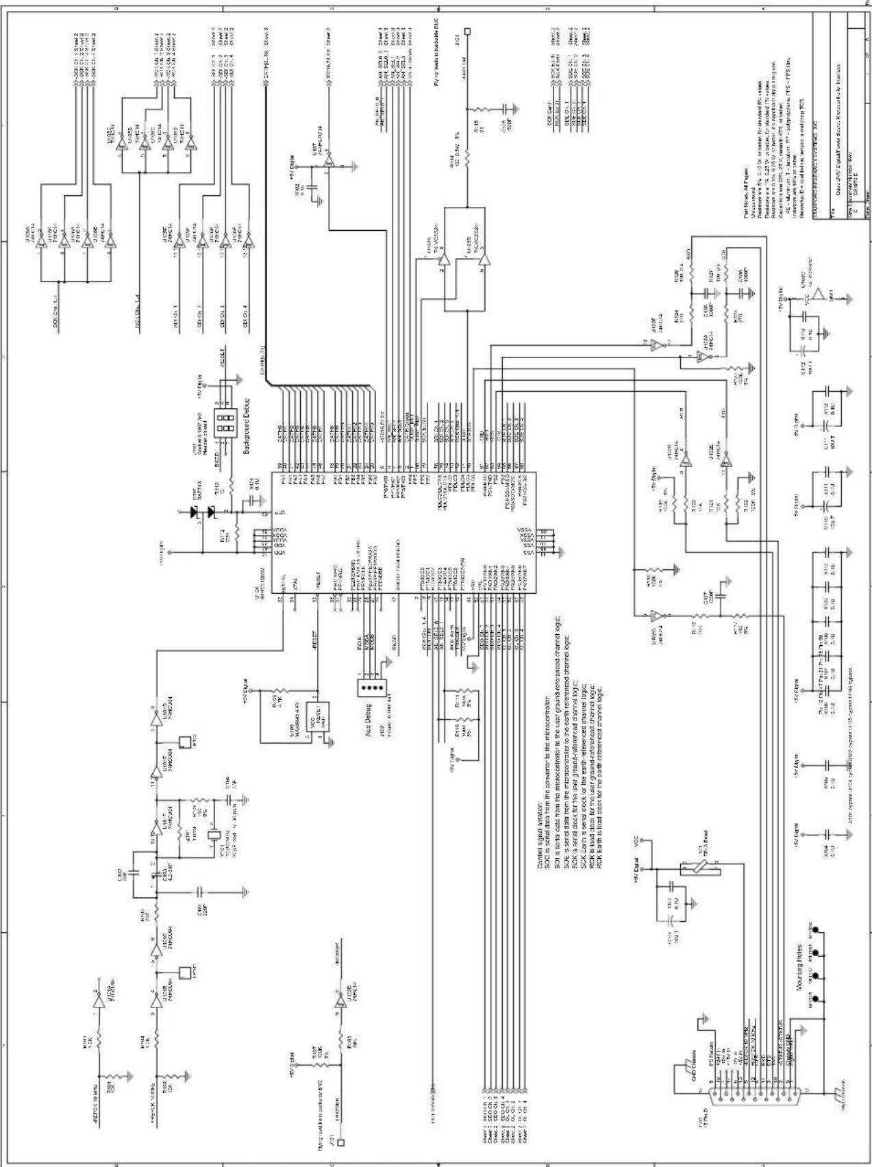
text_image
Electrical schematic diagram of a microcontroller circuit with labeled components, ICs, and signal paths for power management and control.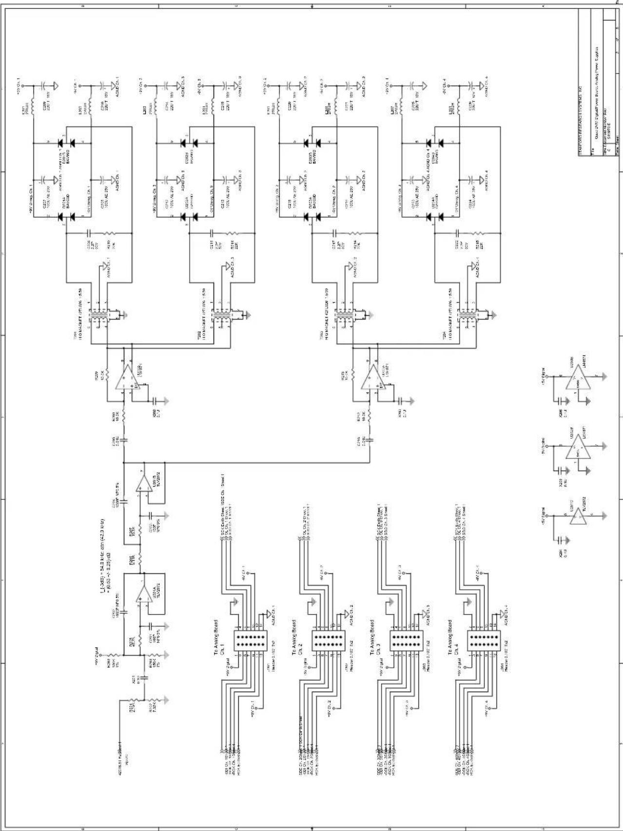
text_image
Electrical circuit diagram with labeled components including transistors, capacitors, resistors, and ICs for various electronic circuits.| 9 | 2 | 3 | 4 | 5 | 6 | 7 | 8 |
| 3 | 5 | 6 | 7 | 8 | |||
| Date: April 1, 2010. December 31, 2010 | |||||||
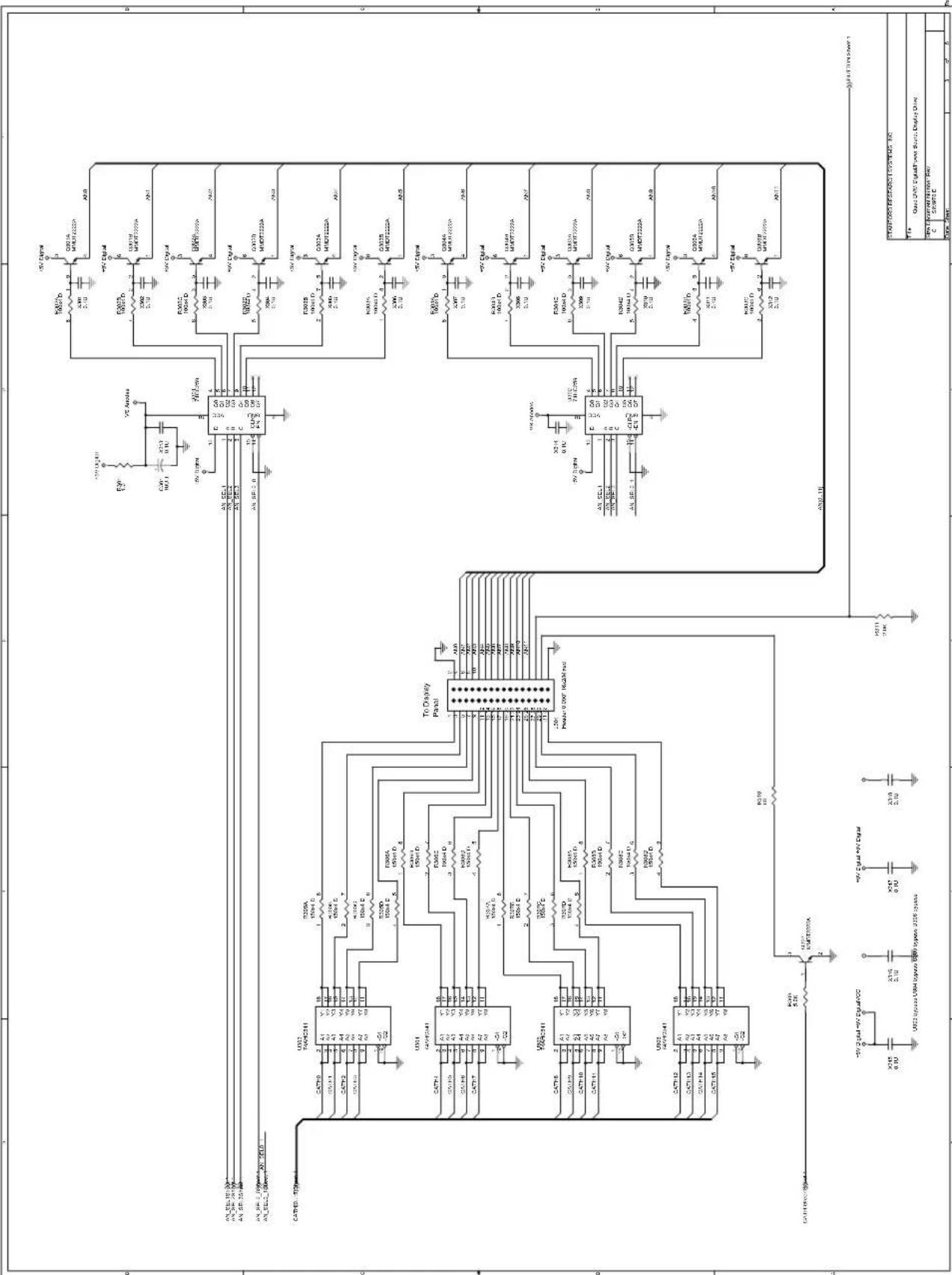
text_image
Electrical schematic diagram with labeled components including resistors, capacitors, and ICs for a power management or control circuit.
text_image
From Display Drive Mounting Holes and Pads COS Structures Post-Front Pins Channel 1 Channel 2 Channel 3 Channel 4 SCH1 V mV zsc SCH2 V mV zsc SCH3 V mV zsc SCH4 V mV zsc SCH5 V mV zsc SCH6 V mV zsc SCH7 V mV zsc SCH8 V mV zsc SCH9 V mV zsc SCH10 V mV zsc SCH11 V mV zsc SCH12 V mV zsc SCH13 V mV zsc SCH14 V mV zsc SCH15 V mV zsc SCH16 V mV zsc SCH17 V mV zsc SCH18 V mV zsc SCH19 V mV zsc SCH20 V mV zsc SCH21 V mV zsc SCH22 V mV zsc SCH23 V mV zsc SCH24 V mV zsc SCH25 V mV zsc SCH26 V mV zsc SCH27 V mV zsc SCH28 V mV zsc SCH29 V mV zsc SCH30 V mV zsc| STANDARD RESEARCH SYSTEMS INC. | ||
| Title:Quad DNTD DigitalPower Source Display Fund | ||
| CPU C | Current Network Pow. CSWTO C | |
| Date Sheet: | 4 5 6 | |

text_image
Signal-Referenced Circuitry Mounting Holds Input passive filtering Signal Under Test: Inverter clamping or two inverter, and connected ACDC Cl. 048 ACDC Cl. 048 The test ACDC Cl. 048 ACDC Cl. 048 ACDC Cl. 048 ACDC Cl. 048 ACDC Cl. 048 ACDC Cl. 048 ACDC Cl. 048 ACDC Cl. 048 ACDC Cl. 048 ACDC Cl. 048 ACDC Cl. 048 ACDC Cl. 048
text_image
Signal-Referenced Circuitry: Earth-Referenced Circuitry: Population J601 to make Channel 1: populate J602 to make Channel 3 Analog switch/ optoFET/F0 control Signal-Referenced Circuitry: Control signal isolation: CLK is a data block X3 EN is enable impedance crossover serve to short user. XM EN is ensure impedance crossover serve to measure user. Servo Pol. is HIGH for a positive user signal. PhotoMOS control Output interface Only possible ONEF or U813, U614, U615 or dial Power Reference and power Standard Research Systems, Inc. Data: 200V Analog Bus: Channel Data Control Source: Google Power Co. Cable: 4.7 GB
text_image
Mounting Holes Signal-Referenced Circuitry Signal Under Test: Input passive filtering U701C 254V/32Hz R021 30.1K U701C 254V/32Hz R021 30.1K U701C 254V/32Hz R021 30.1K U701C 254V/32Hz R021 30.1K U701C 254V/32Hz R021 60V/32Hz U701C 254V/32Hz R021 60V/32Hz U701C 254V/32Hz R021 60V/32Hz U701C 254V/32Hz R021 60V/32Hz U701C 254V/32Hz