CF203 - Smartwatch LG - Free user manual and instructions
Find the device manual for free CF203 LG in PDF.

User questions about CF203 LG
0 question about this device. Answer the ones you know or ask your own.
Ask a new question about this device
Download the instructions for your Smartwatch in PDF format for free! Find your manual CF203 - LG and take your electronic device back in hand. On this page are published all the documents necessary for the use of your device. CF203 by LG.
USER MANUAL CF203 LG
Thank you for purchasing a LG high resolution monitor. It will give you high resolution performance and convenient reliable operation in a variety of video operating modes.
Features
StudioWorks 20i is a 20 inch monitor (18.5 inches viewable) intelligent, microprocessor based monitor compatible with most analog RGB (Red, Green, Blue) display standards, including IBM PC ^ , PS/2 ^ , Apple ^ , Macintosh ^ , Centris ^ , Quadra ^ , and Macintosh II family. It can also be used with a Sun SPARC workstation as well as other sources using the 5 BNC connectors. The monitor provides crisp text and vivid color graphics with VGA, SVGA, XGA, VESA Ergo modes (non-interlaced), and most Macintosh compatible color video cards when used with the appropriate adapter.
The monitor's wide compatibility makes it possible to upgrade video cards or software without purchasing a new monitor.
Digitally controlled auto-scanning is done with the microprocessor, for horizontal scan frequencies between 30 and 85KHz, and vertical scan frequencies between 50 and 120Hz. The microprocessor based intelligence allows the monitor to operate in each frequency mode with the precision of a fixed frequency monitor.
This monitor supports DDC, DDC2B, DDC2AB.
The microprocessor based digital controls allow you to conveniently adjust a variety of image controls by using the OSD (On Screen Display).
The monitor is shipped with 12 factory pre-programmed video modes, 8 of them permanently resident. In addition, there are 20 user storable modes, for a total of 32 memory modes.
With a front-mounted selector for BNC and VGA input selection, up to 2 pc's may be connected to the StudioWorks 20i at the same time, with a simple push-button selection between the two sources.
This monitor is capable of producing a maximum horizontal resolution of 1600 dots and a maximum vertical resolution of 1280 lines. It is well suited for CAD work and sophisticated windowing environments.
For greater user health and safety, this monitor complies with the stringent Swedish Nutek MPRII requirements for low radiation emissions.
For low cost of monitor operation, this monitor is certified as meeting the EPA Energy Star requirements, and utilizes the VESA Display Power Management Signalling (DPMS) protocol for power saving during non-use periods.
Monitor Registration
The model and serial numbers are found on the rear of this unit. These numbers are unique to this unit and not available to others. You should record requested information here and retain this guide as a permanent record of your purchase. Staple your receipt to this page.
| Date of Purchase | : |
| Dealer Purchased From | : |
| Dealer Address | : |
| Dealer Phone No. | : |
| Model No. | : |
| Serial No. | : |
Notice
All rights reserved. Reproduction in any manner, in whole or in part, is strictly prohibited without the written permission of LG Electronics Inc.
Trademark Acknowledgments
LG is a trademark of LG Electronics Inc.
IBM is a registered trademark and VGA is a trademark of International Business Machines Corporation.
WARNING : To reduce the risk of fire or electric shock, do not expose this appliance to rain or moisture.
This unit has been engineered and manufactured to assure your personal safety, but improper use can result in potential electrical shock or fire hazard. In order not to defeat the safeguards incorporated in this monitor, observe the following basic rules for its installation, use, and servicing. Also, follow all warnings and instructions marked directly on your monitor.
On safety
-
Use only the power cord supplied with the unit. In case you need another power cord, make sure that it is certified by the applicable standards (UL/CSA or VDE) if not being provided by the supplier.
-
Operate the monitor only from a power source indicated in the specifications of this manual or listed on the monitor. If you are not sure what type of power supply you have in your home, consult your dealer.
-
Overloaded AC outlets and extension cords are dangerous. So are frayed power cords and broken plugs. They may result in a shock or fire hazard. Call your service technician for replacement.
-
DO NOT OPEN THE MONITOR. There are no user-serviceable components inside. There are Dangerous High Voltages inside, even when the power is Off. Contact your dealer If the monitor is not operating properly.
-
To avoid personal injury:
■Do not place the monitor on a sloping shelf unless properly secured.
■Use only a stand recommended by the manufacturer.
■Do not try to roll a stand with small casters across thresholds or deep pile carpets.
- To prevent Fire or Hazards:
■Always turn the monitor Off if you leave the room for more than a short period of time. Never leave the monitor On when leaving the house.
- Keep children from dropping or pushing objects into the monitor's cabinet openings. Some internal parts carry hazardous voltages.
■ Do not add accessories that have not been designed for this monitor.
■ During a lightning storm or when the monitor is to be left unattended for an extended period of time, unplug it from the wall outlet.
■ Do not bring magnetic devices such as magnets or motors near the picture tube.
On installation
- Do not allow anything to rest upon or roll over the power cord. Do not place the monitor where the power cord is subject to damage.
- Do not use this monitor near water such as near a bathtub, wash-bowl, kitchen sink, laundry tub, in a wet basement, or near a swimming pool.
- Monitors are provided with ventilation openings in the cabinet to allow the release of heat generated during operation. If these openings are blocked, built up heat can cause failures which may result in a fire hazard. Therefore, NEVER:
■ Block the bottom ventilation slots by placing the monitor on a bed, sofa, rug, etc.
■ Place the monitor in a built-in enclosure unless proper ventilation is provided.
■ Cover the openings with cloth or other material.
■ Place the monitor near or over a radiator or heat source.
On cleaning
■ Unplug the monitor before cleaning the face of the picture tube.
■ Use a slightly damp (not wet) cloth. Do not use an aerosol directly on the picture tube because overspray may cause electrical shock.
On repacking.
■ Do not throw away the carton and packing materials. They make an ideal container in which to transport the unit. When shipping the unit to another location, repack it in its original material.
Connecting the Monitor
On the back of the monitor are three plug-in connections: one for the AC power cord, and the others, for the signal cable from the video card.
1. AC Power Connection
One end of the AC power cord is connected into the AC power connector on the back of the monitor. The other end is plugged into a properly grounded three-prong AC outlet. The monitor's auto-sensing power supply can automatically detect 100-120V AC or 200-240V AC, 50 or 60Hz.
2. Signal Cable Connection
The connectors for the signal cable are located on the back of the monitor. The BNC and 15 pin VGA connectors on the back of the monitor allow for a wide variety of video controllers to be connected to the monitor. Examples of signals that might be sent to the monitor include signals from IBM PC and compatibles, Apple Macintosh, Centris, Quadra and SPARC workstations.
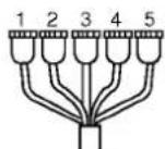
The supplied signal cable consists of a 15 pin VGA connector on one end, and 5 BNC connectors on the other, suitable for connections to an IBM PC or compatible, or other equipment requiring a 5 BNC output.
Other generic cables or adapters may be used for connections to your equipment, as long as they meet the compatible signal requirements to activate this monitor see page 22 for input specifications. For Apple Macintosh use, a separate plug adapter is needed to change the 15 pin high density (3 row) D-sub VGA connector on the supplied cable to a 15 pin 2 row connector. Examples of typical connections are shown below. Select the connection example that fits your needs.
A) Connection to any IBM VGA PC compatible system
Figure 3 shows the signal cable connections from the monitor to the Video Graphics Array (VGA) port typical in an IBM PC or PC compatible. This also applies to any graphics video card for PC-CAD or workstation that has a 15 pin high density (3 row) D-Sub connector.
- Power off both the monitor and PC.
- Connect the signal 15 pin VGA connector of the supplied signal cable to the output VGA video connector on the PC.
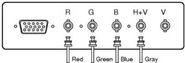
- Connect the 5 BNC connectors to the inputs on the back of the monitor, matching cable colors to the letters labeled on the back of the monitor as:

text_image
R G B H+V V Red Green Blue Gray Black (Rear of Monitor)- Power ON the PC, then the monitor.
- Push the BNC/D-SUB button (inside the front panel) to select and illuminate the BNC green light on the front panel (below the Power LED light). If you see the "SELF DIAGNOSIS" message, press the BNC/D-SUB button again.
- After using the system, power OFF the monitor, then the PC.
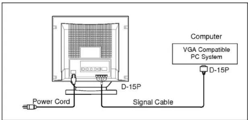
text_image
Power Cord D-15P Signal Cable Computer VGA Compatible PC System D-15PFigure 3.
B) Connecting to an Apple Macintosh II, Centris and Quadra
Figure 4 shows the connection to an Apple Macintosh, using a separately purchased adapter.
- Power OFF both the monitor and the PC.
- Connect the 5 BNC connectors of the supplied signal cable to the inputs on the back of the monitor, matching the cable colors to the letters labeled on the back of the monitor as:

text_image
R G B H+V V Red Green Blue Gray Black (Rear of Monitor)- Locate the appropriate MAC to VGA adapter block at your local computer store. This adapter changes the high density 3 row 15 pin VGA connector to the correct 15 pin 2 row connection to mate with your MAC. Attach the other end of the signal cable to the side of the adapter block with 3 rows.
- Connect the attached adapter block/signal cable to the video output on your MAC.
- Power ON the PC, then the monitor.
- Push the BNC/D-SUB button (inside the front panel) to select and illuminate the BNC green light on the front panel (below the Power LED light). If you see the "SELF DIAGNOSIS" message, press the BNC/D-SUB button again.
- After using the system, power OFF the monitor, then the PC.

text_image
Power Cord Signal Cable Computer Apple Macintosh ADAPTER 15P D-15PFigure 4.
Notes on using the BNC connectors with other types of video cards. Fillow the example that fits your needs.
① IN CASE OF COMPOSITE SYNC ON GREEN VIDEO SIGNAL (SYNC ON GREEN):
Connect R,G and B video signals to BNC receptacles on the back of the monitor, respectively.

text_image
R G B H+V V Red Green Blue② IN CASE OF EXTERNAL COMPOSITE SYNC SIGNAL:
Connect R, G and B video signals and Composite sync signal to BNC receptacles on rear panel, respectively.
text_image
R G B H+V V Red Green Blue Gray③ IN CASE OF SEPARATE HORIZONTAL AND VERTICAL SYNC SIGNALS:
Connect R, G and B video signals and horizontal and vertical sync signals to BNC receptacles on rear panel respectively.
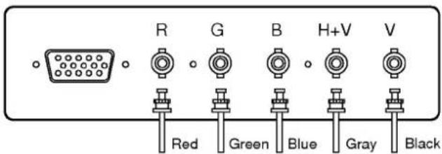
text_image
R G B H+V V Red Green Blue Gray BlackLocation and Function of Controls
Front View
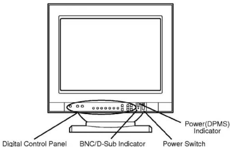
text_image
Digital Control Panel BNC/D-Sub Indicator Power(DPMS) Indicator Power SwitchRear View
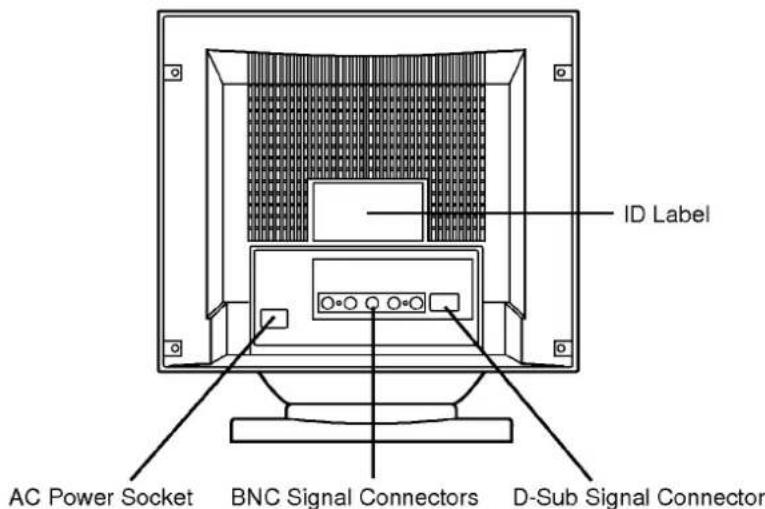
text_image
ID Label AC Power Socket BNC Signal Connectors D-Sub Signal ConnectorUser Controls
Each control is identified by number, and individually described.

text_image
① BNC/D-Sub Select button ② Degaussing ③ Memory recall button ④ Adjustment function buttons ⑤ Adjustment Control buttons ⑥ Brightness Control button ⑦ Contrast Control buttonControl Names
① BNC/D-SUB
When this button is pressed, input connector can be switch between the BNC and 15 pin VGA inputs. When the BNC input is selected, the front panel BNC light is illuminated.
② Degaussing
■A momentary push type switch that is used to eliminate possible color shading or impurity.
■Degauss is also automatically activated as soon as the power is supplied even if the degaussing button is not pressed.
③ Memory recall button.
■Video Mode Recall: When the button is pressed, the input signal data return to the factory-set delivery level (Mode 1, 2, 3).
■Color coordinate Recall: When the button is pressed, the color coordinate (9300 °K, 7200 °K return to the factory-set delivery level at COLOR SELECT message.
④ Adjustment function buttons
■Push the adjustment function select buttons to select the desired adjustment function.
⑤ Adjustment control buttons
■Push and hold the increase(+) or decrease(-) buttons for the desired adjustment. All adjustments are automatically memorized.
⑥ Brightness control button
■Adjust the brightness of the image
■Push and hold the plus(+) button to increase or the minus(-) button to decrease the Brightness level.
⑦ Contrast control button
■Adjust the contrast of the image
■Push and hold the plus(+) button to increase or minus(-) button to decrease the contrast level.
Function Controls
All functions (except Power ON/OFF) are adjusted from the microprocessor based digital controls located on the inside front cover door. Open and close the door by pressing firmly on the middle of the door, marked by the : : : symbol.
The following is a description of use for each button.
Help
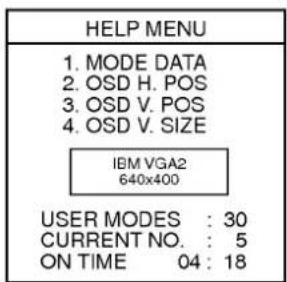
The HELP button lets you check mode data in memory, change the size and position of the OSD menu, review the current resolution active, list the current memory mode number being used, and show you how long the monitor has been ON since you last turned on the monitor (shown in hours and minutes).
When you press the HELP button once, the HELP MENU On Screen Display (OSD) will appear on the screen with the first item highlighted, as shown below:
text_image
HELP MENU 1. MODE DATA 2. OSD H. POS 3. OSD V. POS 4. OSD V. SIZE IBM VGA2 640x400 USER MODES : 30 CURRENT NO. : 5 ON TIME 04 : 18Each press of the HELP button allows access to the following:
- MODE DATA -- review the stored resolution modes in memory.
- OSD H. POS. -- move the OSD menu left or right.
- OSD V. POS. -- move the OSD menu up or down.
- OSD V. SIZE -- Increase or decrease vertical size of the OSD menu.
Each press of the HELP button will select one of the above 4 items, indicated by the highlighted item.
Use the ADJUST +/- buttons to either scroll through the MODE DATA (1) or change the OSD menu position or size (2,3,4). A few moments after you have selected or adjusted an OSD menu item, the menu will disappear.
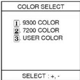
COLOR SELECT/DDC ON, OFF
Generally, 9300°K and 7200°K are color temperature standards used in desktop publishing and design work.
You may select either of these two factory set levels, or you can set your own color levels by selecting USER COLOR and then adjusting each of the Red, Green, Blue levels as described in the following RGB SELECT section.
When you push the COLOR SELECT button, the color select menu will appear, with the currently used mode highlighted (magenta color), as shown below:
text_image
COLOR SELECT ① 9300 COLOR ② 7200 COLOR ③ USER COLOR SELECT : +, -Press the ADJUST +/- buttons to select the desired color temperature. The OSD menu will disappear after a few moments.
Note: You may also adjust the color levels (R,G,B) when you have selected either of the factory preset 9300°K or 7200°K color temperatures. To do this, simply select the color temperature you want to start with, and then adjust the R,G,B levels as described in the RGB SELECT section below.
To RESET the 9300*K or 7200*K color levels back to the factory preset levels:
- Push COLOR SELECT, and select 9300°K or 7200°K to be reset by using the ADJUST +/- buttons.
- While the COLOR SELECT OSD is still shown on-screen, push the RECALL button. (If the menu disappeared, press COLOR SELECT again and then the RECALL button.)
When this button is pushed once more again while COLOR SELECT MENU is ACTIVE, DDC MENU will be displayed with OSD. Then you can select DDC ON/OFF function by using the plus(+) or the minus(-) button. When DDC ON (+ button) is selected, the monitor will be operated one of the DDC1/DDC2B/DDC2AB (Access Bus) mode depends on the input condition from HOST system.
When DDC OFF(- button) is selected, the monitor will be disabled from all DDC modes.
HORIZONTAL POSITION and SIZE control
The button ☐ ↔ allows adjustment of the display's horizontal position and size.
To adjust the horizontal position:
- Press the ☐ button once. The OSD H-POSITION as shown below will be displayed:

text_image
H-POSITION 100 NEXT : ← → H-SNote: ADJUST + = right
ADJUST - = left
- Press the ADJUST +/- buttons (while the H-POSITION OSD is still displayed) to move the display right or left. The adjustment will be automatically memorized and the OSD will disappear in a mement.
To adjust the horizontal size:
- Press the □ button twice. The OSD H-SIZE as shown below will be displayed:

text_image
H-SIZE 100 NEXT : OFFNote: ADJUST + = bigger
ADJUST - = smaller
- Press the ADJUST +/- buttons (while the H-SIZE OSD is still displayed) to make the display bigger or smaller. The adjustment will be automatically memorized and the OSD will disappear in a moment.
VERTICAL POSITION and SIZE Control


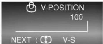
The 📋 button allows adjustment of the display's vertical position and size.
To adjust the vertical position:
- Press the button once. The OSD V-POSITION as shown below will be displayed:
text_image
V-POSITION 100 NEXT : ↻ V-SNote: ADJUST + = up ADJUST - = down
- Press the ADJUST +/- buttons (while the V-POSITION OSD is still displayed) to move the display up or down. The adjustment will be automatically memorized and the OSD will disappear in a moment.
To adjust the vertical size:
- Press the button twice. The OSD V-SIZE as shown below will be displayed:
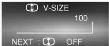
text_image
V-SIZE 100 NEXT : OFFNote: ADJUST + = bigger ADJUST - = smaller
- Press the ADJUST +/- buttons (while the V-SIZE OSD is still displayed) to make the display bigger or smaller. The adjustment will be automatically memorized and the OSD will disappear in a moment.
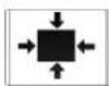
SIDE PINCUSHION and TRAPEZOID Control
The button ☐☐ allows correction of screen abnormalities that may come up when changing video modes.
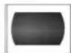
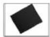
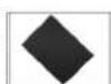
The side pincushion control corrects image abnormalities showing a bending of the left and right vertical sides of the display, such as

OR
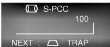
The trapezoid control corrects image abnormalities showing a wider top or bottom display, such as

OR
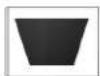
To adjust the side pincushio (sometimes also called barrel) control:
- Press the ☐ button once. The OSD S-PCC as shown below will be displayed:
text_image
S-PCC 100 NEXT : TRAPNote: ADJUST + = wider ADJUST - = narrower
- Press the ADJUST +/- buttons (while the S-PCC OSD is still displayed) to move the sides in or out. The OSD will disappear shortly after buttons are pressed.
To adjust the trapezoid control:
- Press the ☐ button twice. The OSD TRAPEZOID as shown below will be displayed:

text_image
TRAPEZOID 100 NEXT : OFFNote: ADJUST + = wider top ADJUST - = narrower top
- Press the ADJUST +/- buttons (while the TRAPEZOID OSD is still displayed) to move the top width wider or narrower. The OSD will disappear shortly after buttons are pressed.
ZOOM and TILT control
The zoom and tilt button lets you adjust the display size (vertical and horizontal simultaneously) and tilt (rotation) of the image on the screen. Image size changes when you change video or resolution modes, so a single control to adjust screen size is convenient. Changes in location of the monitor may affect the display in such a way that the image on the screen looks tilted a little. The tilt control easily remedies this situation.
To adjust the ZOOM control:
- Press the ZOOM/TILT button once. The OSD ZOOM as shown below will be displayed:

text_image
ZOOM 100 NEXT : TILTNote: ADJUST + = bigger ADJUST - = smaller

- Adjust both the vertical and horizontal size at the same time by pressing the ADJUST +/- buttons. If you find that only the vertical or horizontal size can be made correctly, you may need to adjust the individual horizontal size or vertical size controls to adjust the display for the maximum (edge to edge) display size.
To adjust the TILT control:
- If the displayed image looks tilted when compared to the frame around the picture tube, press the ZOOM/TILT button twice. The OSD TILT will as shown below will be displayed:

text_image
TILT 100 NEXT : TILT OFFNote: ADJUST + = counter clockwise ADJUST - = clockwise
- Adjust the tilt of the display by using the ADJUST +/- buttons, while the TILT OSD is displayed.
Slef Diagnosis
The StudioWorks 20i has a convenient SELF DIAGNOSIS OSD feature that pops up when there may be possible causes of non-operation. The OSD would highlight a possible reason the display is not showing an image.
An example of this may be when you turn on the monitor with no signal cable attached. The monitor will display the SELF DIAGNOSIS OSD menu with the "CHECK S/CABLE" and one of the "STATUS" items highlighted (such as BNC or D-SUB). This would be a clue for you to check the signal connections and to make sure you have the correct input (BNC or D-SUB VGA) selected.
The SELF DIAGNOSIS OSD may also appear if you exceed the monitor's operating limits, such as the maximum resolution of 1600x1280 or the frequency refresh rates of 30-85KHz Horizontal, 50-120Hz Vertical.
The other items on the SELF DIAGNOSIS OSD are actually just feature highlights, letting you know of certain major features of the StudioWorks 20i.
Energy Saving Design
This monitor complies with the EPA's Energy Star program, which is a program designed to have manufacturers of computer equipment build circuitry into their products to reduce power consumption during time of non-use.
When this monitor is used with a "Green" or EPA Energy Star PC, or a PC with a screen blanking software following the VESA Display Power Management Signalling (DPMS) protocol, this monitor can conserve significant energy by reducing power consumption during periods of non-use. When the PC goes into the energy saving mode, the monitor will go into a suspended operation state, indicated by the Power LED light changing from a green color to an orange color. After an extended period in the suspended mode, the monitor will then enter a semi-OFF mode to conserve more energy. In the semi-OFF mode or DPMS OFF mode as we call it in our specifications, the Power LED will still show an orange color. When you awaken your PC by hitting a key or moving the mouse, the monitor will also awaken to its normal operating mode, indicated by the green Power LED light. By following these conventions, the power consumption can be reduced to the following levels:
Normal operation : Maximum 130 Watts
Suspend mode : 15 Watts
DPMS Off : 6 Watts.
Video Memory Modes
This multi-synchronous auto-scanning monitor can automatically detect and display several video modes.
For convenience, the monitor has a 32 mode memory of which 12 modes come from the factory preset to popular video modes as described below.
| Resolution | H-Freq. | V-Freq. | HS. pol | VS. pol | Mode |
| 720 x 400 | 31.467KHz | 70.082Hz | - | + | 1 |
| 640 x 480 | 31.463KHz | 59.929Hz | - | - | 2 |
| 1024 x 768 | 35.522KHz | 43.479Hz | + | + | 3 |
| 640 x 480 | 37.500KHz | 75.000Hz | - | - | 4 |
| 800 x 600 | 46.875KHz | 75.000Hz | + | + | 5 |
| 1024 x 768 | 60.023KHz | 75.029Hz | + | + | 6 |
| 1280 x 1024 | 63.981KHz | 60.020Hz | + | + | 7 |
| 1280 x 1024 | 79.976KHz | 75.025Hz | + | + | 8 |
| 640 x 480 | 43.269KHz | 85.008Hz | - | - | 9 |
| 800 x 600 | 53.674KHz | 85.061Hz | + | + | 10 |
| 1024 x 768 | 68.677KHz | 84.997Hz | + | + | 11 |
| 1152 x 870 | 68.681KHz | 75.062Hz | - | - | 12 |
Modes 13-32 are empty and can accept new video data.
If the monitor detects one of the above signals from your computer's video card, it will recall that mode and any stored image adjustments you may have made before. If the monitor detects a new video mode that had not been present before or not one of the above listed factory presets, it will store a new mode automatically in one of the blank (empty) memory modes (in this example, mode 13). When you now adjust the digital controls to your preference, these image settings will also be stored in mode 13. Whenever your video card or PC switches to the mode that the monitor recognizes as mode 13, your personal image settings will also be recalled.
A note about the video memory modes:
There are a total of 32 video memory modes, generally more modes than you will use at any one time. Of these 32 modes, 8 are permanent, factory fixed modes that cannot be changed. The remaining 24 modes left blank (empty). If you use up the 24 blank modes and still have more new video modes, the monitor will begin to delete modes 9-32 to make room for the new mode storage.
If you use a video card that has a number of resolutions and frequencies that do not correspond to any of the monitor video modes set at the factory, here's what will happen:
1) As the monitor encounters new video data, the monitor will save the new information in the next available empty mode (mode 13 if this is the first new data encountered).
2) If you have used up modes 9-32 with 24 new video modes, and the monitor has another mode it encounters, it will store the new data in mode 32 and delete mode 9, the lowest mode above the permanent factory fixes modes.
3) If even more new modes are encountered by the monitor, each new mode becomes the 32th mode and the old mode 9 is deleted. In summary, if the 32 modes are full and new modes are added, each old mode shifts to a lower memory mode, eventually being deleted if it is forced out of mode 9.
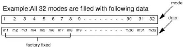
text_image
Example:All 32 modes are filled with following data 1 2 3 4 5 6 7 8 9 - - - - - - - - 30 31 32 m1 m2 m3 m4 m5 m6 m7 m8 m9 - - - - - - - - m30 m31 m32 factory fixed mode dataWhen new data is encountered (new data becomes mode 33)

By designing the monitor this way, you will always have the most common 24 video modes generated by your graphics card available, with your own image settings recalled automatically.
Troubleshooting
*Symptom: No back raster with BNC LED lit or self diagnosis message on back raster appear.
Possible causes:
■The signal cable is not connected.
*Symptom: The power led is illuminated blinking amber or amber.
Possible causes:
■ Display power management mode. (Move mouse to awaken PC.)
■Wrong signal channel (Push BNC/D-Sub button)
■The signal cable is not fastened securely.
■Check the computer power and graphics adapters configuration.
■ The frequency of the sync input is outside the operating range of the monitor.
Mointor Input Limits
Horizontal Frequency:30KHz-85KHz
Vertical Frequency:50Hz-120Hz
The signal cable is incorrectly configured or connected Refer to the page Signal connector pin assignment for reference.
*Symptom: Image is not correctly shaped
Possible causes:
■A new mode is selected.
■ User control has not yet been adjusted. Use the controls to adjust image. Refer to "Location and Function of controls"
*Symptom: "Place the correct wording here to indicate wording on screen when a new mode is encountered : is it "NEW MODE"?" dis played each time you change applications or resolution.
Possible causes: The monitor encountered a new mode. You should adjust the image controls to you liking, and the monitor will memorize this mode and settings for future auto-Recall.
Service
- Unplug the monitor from the wall outlet and refer servicing to qualified service personnel when :
■The power cord or plug is damaged or frayed.
■ Liquid has been spilled into the monitor.
■ The monitor has been exposed to rain or water.
■The monitor does not operate normally following the operating instructions. Adjust only those controls that are covered in the operating instructions. An improper adjustment of other controls may result in damage and often requires extensive work by a qualified technician to restore the monitor to normal operation.
■ The monitor has been dropped or the cabinet has been damaged.
■ The monitor exhibits a distinct change in performance.
■ Snapping or popping from the monitor is continuous or frequent while the monitor is operating. It is normal for some monitors to make occasional sounds when being turned on or off.
- Do not attempt to service the monitor yourself, as opening or removing covers may expose you to dangerous voltage or other hazards. Refer all servicing to qualified service personnel.
- When replacement parts are required, have the service technician verify in writing that the replacements used have the same safety characteristics as the original parts. Use of manufacture specified replacements can prevent fire, shock and other hazards.
- Upon completion of any service or repairs to the monitor, ask the service technician to perform the safety check described in the manufacturer's service manual.
- When a video monitor reaches the end of its useful life, improper disposal could result in a picture tube implosion. Ask a qualified service technician to dispose of the monitor.
Input Specifications
Sync signal types
| Priority | Type | Green video | V. Sync |
| 1 | separate sync | Video | V. sync |
| 2 | composite sync | Video | N.C |
| 3 | sync on video | sync on video | N.C |
(N.C: no connection)
D P M (Display Power Management)
| MODE | H. Sync | V. Sync | Power Consumption | LED Color |
| Normal | On | On | ≤ 130W | Green |
| Stand by | Off | On | ≤ 15W | Blinking Amber |
| Suspend | On | Off | ≤ 15W | Blinking Amber |
| Off | Off | Off | ≤ 6W | Amber |
Signal connector pin assignment

| Pin | Signal (D-Sub) |
| 1 | Red |
| 2 | Green |
| 3 | Blue |
| 4 | Ground |
| 5 | Self-Test |
| 6 | Red Ground |
| 7 | Green ground |
| 8 | Blue Ground |
| 9 | +5V (From PC) |
| 10 | Ground |
| 11 | Ground |
| 12 | SDA |
| 13 | H. Sync |
| 14 | V. Sync |
| 15 | SCL |
| Pin | Signal (5 BNC) | Color |
| 1 | Red | Red |
| 2 | Green | Green |
| 3 | Blue | Blue |
| 4 | H. Sync(H or H+V) | Gray |
| 5 | V.sync | Black |
Specification
Picture tube
20 inch (18.5 inches viewable), 90 degree deflection, Darkface, 0.28mm dot pitch AR-ASC (Anti-Glate Anti-Static Charge) no glare coating
Sync Input
Horizontal Freq.: 30KHz-85KHz (Automatic) Vertical Freq.: 50Hz-120Hz (Automatic) Input Form : Separate, TTL, positive/negative Composite, TTL, positive/negative Signal input : 15pin D-Sub connector/5 BNC connector
Video Input
Display Area : 365x270mm/14.4"x10.6 (HxV) Input Form : Separate, RGB Analog, 0.7Vp-p/75 ohm, positive
Power Input
100-240V AC 60/50Hz 2.0A
Power Consumption : 130 Watts Max 15 Watts Suspend mode 6 Watts DPMS-off mode
Dimensions (WxHxD)
482mmx424mmx500mm(19"x16.7"x19.7")
Weight (net)
30kg (66 lbs)
Information in this document is subject to change without notice and does not represent a commitment on the part of LG Electronics Inc.
Table of Contents
Introduction ....1
Monitor Registration....2
Important Precautions....3
Connecting the Monitor....5
Location and Function of Controls....9
User Controls ....10
Function Controls....11
Self Diagnosis....17
Energy Saving Design 17
Video Memory Modes....18
Troubleshooting Tips....20
Service....21
Input Specifications....22
FCC Compliance Statement
This equipment has been tested and found to comply with the limits for a Class B digital device pursuant to Part 15 of the FCC Rules. These limits are designed to provide reasonable protection against harmful interference in a residential installation.
This equipment generates, uses and can radiate radio frequency energy, and if not installed and used in accordance with the instructions, may cause harmful interference to radio communications. However, there is no guarantee that interference will not occur in a particular installation.
If this equipment does cause harmful interference to radio or television reception (which can be determined by turning the equipment off and on), the user is encouraged to try to correct the interference by using one or more of the following measures:
- Reorient or relocate the receiving antenna.
- Increase the separation between the equipment and the receiver.
- Connect the equipment into an outlet on a circuit different from that to which the receiver is connected.
- Consult the dealer or an experienced radio/TV technician for help.
Caution: Changes or modifications not expressly approved by LG Electronics Inc. for compliance could void the user's (or your) authority to operate the equipment. Only peripherals (digital input/output devices, terminals, printers, etc.) certified to comply with the Class B limits may be attached to this monitor. Operation with non-certified peripherals is likely to result in interference to radio and TV reception.
Only shielded Signal Cables may be used with this System.
Canadian D. O. C Notice
Suggested text for the notice indication compliance with this Standard:
This Class B digital apparatus meets all requirements of the Canadian Interference-Causing Equipment Regulations.
DECLARATION OF CONFORMITY
We
LG Electronics Inc.
184 Kongdan-dong Kumi-city KOREA
declare on our own responsibility, that the product:
Kind of equipment: Monitor
Type-designation: StudioWorks 20i
is in compliance with following norm(s) or documents:
EN 55022/4.1982, EN 50082-1/1992
EN 60555 part 2 and 3 1987
Accredited testlaboratory:
MIKES PRODUCT SERVICE GmbH
Ohmstraße 2-4
94342 Strasskirchen
LG Electronics U.K. Ltd.
- Mar. '95
place and date of issue
Mike.P.Burns (SVC MANAGER)
Manufacturer/Authorized representative name and signature