
MPWT50 - Unspecified BOSS - Free user manual and instructions
Find the device manual for free MPWT50 BOSS in PDF.

| Product Type | 2-Way Marine/Powersports Roll Cage/Waketower Speaker Pods |
| Mid-Bass Driver | 5.25" (133 mm) Poly Injection Cone with Rubber Surround |
| Tweeter | 1" (25 mm) PEI Dome Tweeter |
| Crossover | Built-in |
| Impedance | 4 Ohms |
| Power Handling (Max) | 500 Watts |
| Frequency Response | 140 Hz - 20 kHz |
| Sensitivity | 92 dB (1 watt/1 meter) |
| Mounting Tube Compatibility | 1.5" - 2" (38 - 51 mm) diameter |
| Waterproof Rating | Fully waterproof |
| Dimensions (W x H x D) | 6.38" × 9" × 6.19" (162 × 229 × 157 mm) |
| Gross Weight (in gift box) | 8.05 lbs (3.65 kg) |
| Included Accessories | 2 speaker pods, 4 each of 2 sizes aluminum mounting bands, rubber strips, rubber pads, M6 screws, washers, locknuts |
| Recommended Applications | Wake tower, roll cage, marine vessels |
| Driver Material | Poly injection cone, rubber surround |
| Installation Method | Clamp-on with adjustable aluminum bands |
| Color | Black |
| Brand | BOSS Audio Systems |
| Model | MPWT50 |
Frequently Asked Questions - MPWT50 BOSS
User questions about MPWT50 BOSS
0 question about this device. Answer the ones you know or ask your own.
Ask a new question about this device
Download the instructions for your Unspecified in PDF format for free! Find your manual MPWT50 - BOSS and take your electronic device back in hand. On this page are published all the documents necessary for the use of your device. MPWT50 by BOSS.
USER MANUAL MPWT50 BOSS
natural_image
Two black outdoor sound amplifiers with visible fan blades and a 'TRE' logo on the front (no text or symbols on the devices themselves)BOSS®
AUDIO SYSTEMS
MPWT50
5.25" (133 mm) 2-Way Marine/Powersports Roll Cage/Waketower Speaker Pods
Congratulations on your purchase of a BOSS product.
It has been engineered to bring you the highest level of performance. Its quality will afford you years of listening pleasure.
Thank you for making your choice for audio entertainment!

Specifications
Mid Bass Driver:
5.25" (133 mm)
Poly injection cone
Rubber surround
Tweeter:
1" (25 mm) PEI dome tweeter
Crossover network:
Built-in
Impedance:
4 Ohms
Power Handling:
Max 500 Watts
Frequency Response:
140Hz - 20kHz
Sensitivity:
92dB (1 watt/1 meter)
Dimensions (W x H x D):
6.38" × 9" × 6.19"
(162 × 229 × 157 mm)
Gross Weight (in gift box):
8.05 lbs (3.65 kg)
USER MANUAL
Introduction
Your new MPWT50 waketower speakers are high-power, fully-waterproof 2-way systems featuring 5.25" drivers and a 1" PEI dome tweeter.
BOSS understands that wake tower speakers are used in many different types of installations. Our versatile mounting solutions give you the ability to attach our wake tower speakers to mounting tubes with diameters of 1.5" - 2" (38 - 51mm).
What is included?
Before you begin installation, please check that your product contains the following contents:
• (2) Speaker pod
• (4) 130x14x2mm rubber mounting strip
• (4) 120x14x1mm rubber mounting strip
• (2) 48x30x2mm rubber mounting pad
• (4) 2" mounting aluminum band for 2" and 1.875" installation.
• (4) 1.75" mounting aluminum band for 1.75" and 1.5" installation.
• (4) M6 locknut
• (4) M6 flat washer
• (4) M6x60mm screw
Safety considerations when installing
Please remember that these are heavy products that will be installed in a boating environment. These vehicles can travel at high speeds and be unstable. So please consider this and use extreme caution.
Some safety considerations include:
1- Do not mount the speakers in a location where someone may either walk into or strike their head. During a turbulent ride, please make sure that you do not loosen footing and fall or hit the unit, or it may cause injury.
2- Secure the wires to the speakers in multiple locations along their route to your audio source, so that there are no hanging loops of wire. Having unsecure wires in any hanging conditions can cause entanglement and injury.
3- Tighten the aluminum bands with rubber inserts using care. Do not over compress the rubber inserts. After installation is complete, please recheck all bolts and tighten them further if needed before taking your boat or vessel out for an audio adventure.
4- Do not install these speakers where they may block the view of the pilot and prevent safe operation of the vessel or vehicle.
It is strongly recommended that you work with an assistant to install these speakers.
Installation instructions
STEP1
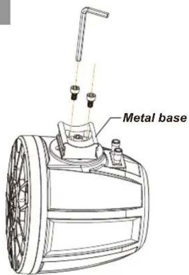
To adjust the mounting angle, loosen the metal base of the mounting band by unbolting the two screws.
Make sure to put all components of the mounting hardware in a safe location.
STEP2
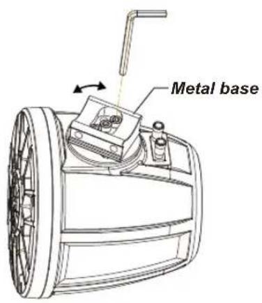
Twist the metal base to determine the optimal mounting angle for the speaker on the cage bar. Then secure the metal base by tightening the two screws.
STEP3
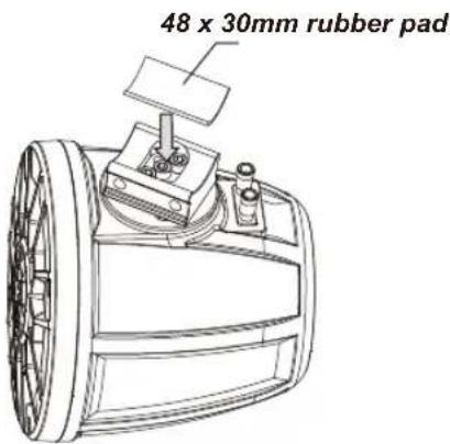
Place a supplied rubber (48 x 30 mm) pad on the metal base of the mounting band to prevent abrasion and secure clamping.
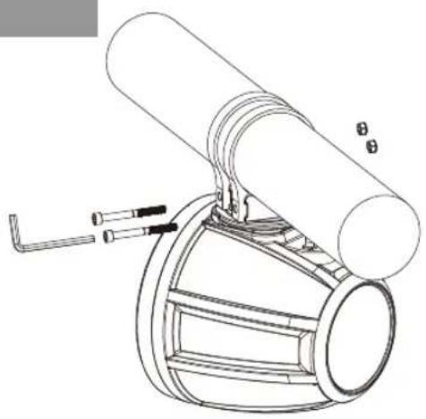
STEP4
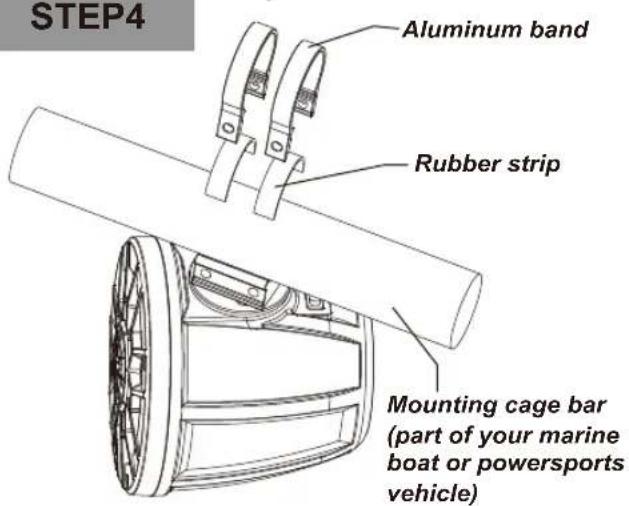
Place two supplied rubber strips around the cage bar to prevent abrasion and secure clamping.
Then push two supplied aluminum bands over the cage bar, and align the aluminum bands with the metal base on the speakers.
natural_image
Technical line drawing of a mechanical assembly with cylindrical components and a curved base (no text or symbols)As illustrated, secure the aluminum bands to the metal base using a pair of M6 x 60mm screws, M6 flat washers, and M6 locknuts. The locknuts must be installed into the hex shaped recess on one end of each aluminum band.
Hand-tighten the screws to the degree which allows just enough freedom to rotate the speaker around the cage bar.
STEP6STEP5
natural_image
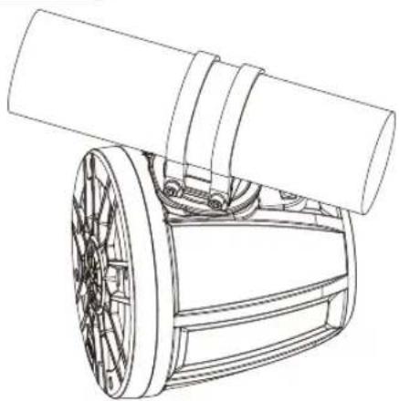
Technical line drawing of a mechanical component with cylindrical shaft and flanged base (no text or symbols)Speaker installation now completes.
Speaker wiring

BOSS Audio Systems
3451 Lunar Court · Oxnard, CA 93030
www.bossaudio.com
805-751-4853 Customer Service
Tech Support: www.bossaudio.com/support


Warning:
- For safety, disconnect the negative terminal on the source battery prior to wiring.
- Note your amplifier impedance stability prior to wiring.
- Use only high quality marine-grade speaker wires. Make sure wires are not squeezed or damaged by sharp edges.
1 Speaker wire connection
Connect one end of speaker wires (not included) to the terminals on the speaker pod, and the other end to the audio outputs on your 12V amplifier. Make sure to observe polarity.
BOSS®
AUDIO SYSTEMS

Brand : BOSS
Model : MPWT50
Category : Unspecified