Crush Delay V3 - Synthesizer Befaco - Free user manual and instructions
Find the device manual for free Crush Delay V3 Befaco in PDF.

User questions about Crush Delay V3 Befaco
0 question about this device. Answer the ones you know or ask your own.
Ask a new question about this device
Download the instructions for your Synthesizer in PDF format for free! Find your manual Crush Delay V3 - Befaco and take your electronic device back in hand. On this page are published all the documents necessary for the use of your device. Crush Delay V3 by Befaco.
USER MANUAL Crush Delay V3 Befaco
text_image
CRUSH DELAY FAST CLEAN TIME DRY / WET FEEDBACK IN VOL OUT SEND BIFACOCRUSH DELAY
USER MANUAL
POWERING | THANKS FOR PURCHASING A MODULE FROM BEFACO! THE MODULE BEFORE YOU PLUG THIS MODULE IN...
-
Disconnect your cabinet from the mains.
-
Triple check the power cord polarity. The coloured line on the cable (pin number one) is the -12V rail.
-
If you plug the module backwards you might burn it out and unfortunately this is not covered by the warranty.
-
If you have any questions about this product please send them to: befacosynth@gmail.com

text_image
-12VINTRODUCTION | WHAT IS CRUSH DELAY?
Crush Delay is an special Echo-Delay unit based on the PT2399 IC, which although able to offer 400ms of clean delay, having a special talent for generate noisy textures. The module bases its operation on control the PT2399 chip with circuit bending techniques, converting the unit in an advance VC digital noise generator. This third version comes with some interesting new features like redesigned VCAs circuits, more clean range and less depth.
MODULE REFERENCE
PANEL OVERVIEW
text_image
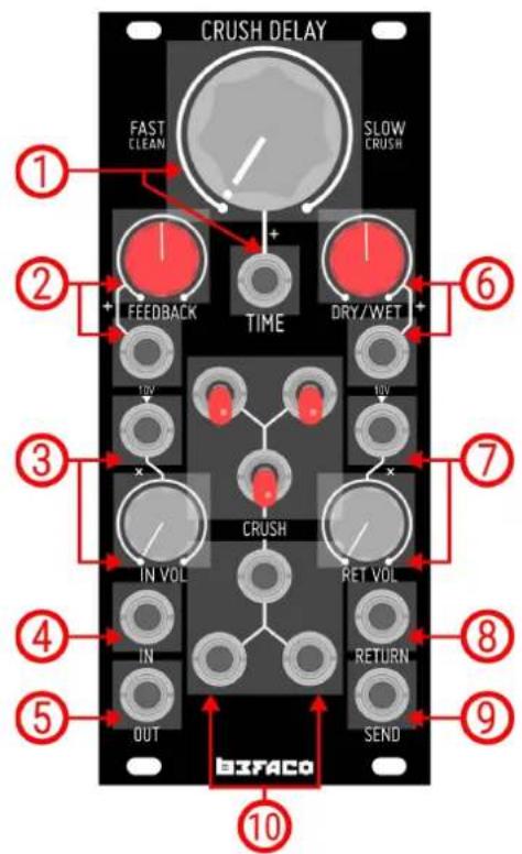
CRUSH DELAY FAST CLEAN SLOW CRUSH 1 2 + + FEEDBACK TIME DRY/WET 6 10V 10V 3 x CRUSH IN VOL RET VOL 4 IN RETURN 5 OUT SEND 8 9 10 BIFACO- Time
Manual and CV control for the delay time. The signal starts to Crush from knob middle position to fully clockwise.
- Feedback
Amount of feedback present in the signal path. It can be set either manually and CV via its dedicated input.
- In Vol
Volume of the main input signal. Its dedicated CV input allows it to act as a regular VCA circuit.
- IN
Main audio input of the module.
- OUT
Main audio output of the module.
- Dry/Wet
Amount of Dry and Wet signals present in the output. It can be set either manually and CV.
- Ret Vol
Volume of the signal present in Return input. Its dedicated CV input allows it to act as a regular VCA circuit.
- Return
Return audio input. Its summed to the main audio input before enters into the delay circuit.
- Send
Outputs the fully Wet signal.
- Crush Section
On/Off switches and gate inputs for the different Crush settings.
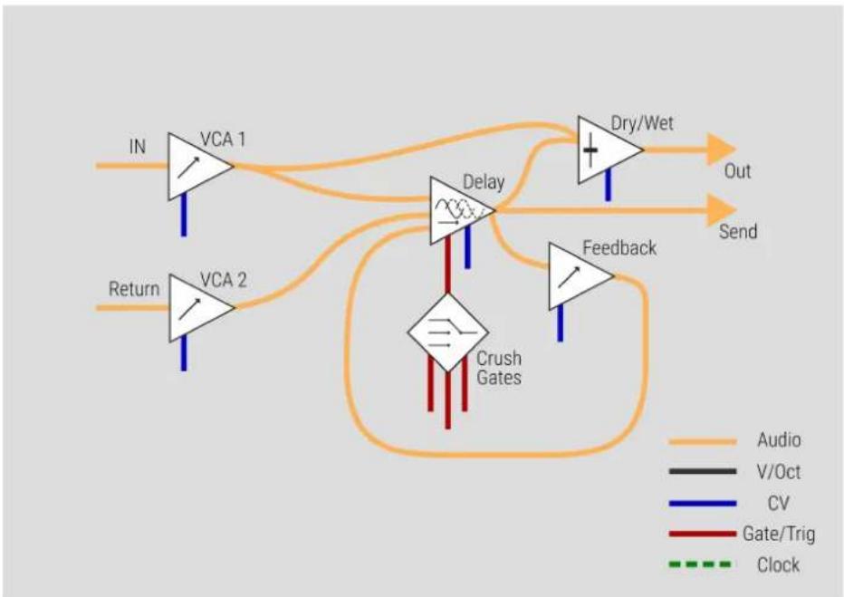
MODULE REFERENCE | BLOCK DIAGRAM
SIGNAL PATH
With a quick look to the block diagram, we can easily understand Crush Delay signal flow.
The module has two inputs (IN and Return) that go to the Delay circuit through a dedicated VCA for each one. The main difference between both inputs is that the signal feeded into IN is going to the Dry/Wet circuit too, not only to the Delay, allowing you to control balance between the original and the processed signal, present at the main output (OUT).
The signal is processed by the Delay circuit, which is affected by the Crush section. It degrades the signal at slow rates in different ways, depending of the position of the three Crush switches or by the presence of gate signals at the Crush inputs.
flowchart
graph TD
    IN["IN"] --> VCA1["VCA 1"]
    IN --> VCA2["VCA 2"]
    VCA1 --> Delay["Delay"]
    VCA2 --> Delay
    Delay --> DryWet["Dry/Wet"]
    DryWet --> Out["Out"]
    DryWet --> Send["Send"]
    Feedback["Feedback"] --> Delay
    Feedback --> Attack["Crush Gates"]
    Attack --> Return["Return"]
    style VCA1 fill:#f9f,stroke:#333
    style VCA2 fill:#f9f,stroke:#333
    style Delay fill:#ccf,stroke:#333
    style Attack fill:#cfc,stroke:#333
    style DryWet fill:#fcc,stroke:#333
    style Feedback fill:#fcc,stroke:#333
    style Attack fill:#ffc,stroke:#333
After being processed, the signal is routed to three different paths. The first one goes into Dry/Wet, where it's mixed with the original input signal (IN) before going to the main output (OUT). The second one is returned to the Delay circuit through another VCA (Feedback), controlling the amount of repetitions of the wet signal. Finally the last one goes directly to the Send output.
FUNCTIONAL BLOCKS
INPUTS

text_image
IN IN VOL ININ
Is the main input circuit of the module. The signal goes through a dedicated VCA to the Delay and Dry/Wet circuits. The IN VOL pot controls the volume of the signal when nothing is patched at its CV Input. This CV Input is normalled to 10V, so with a signal present on it, the IN VOL pot will act as attenuator of that CV signal.
RETURN
Working as second input section of the module, Return has the same internal structure of the IN circuit, the main difference between both is that the signal present at Return input is not routed to the Dry/Wet circuit, only to Delay. As well as IN, Return has a dedicated VCA with manual (RET VOL) and CV controls. The CV input of the VCA is also normalled to 10V, so RET VOL will act as attenuator of any CV signal present on it.
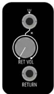
text_image
10V RET VOL RETURNFUNCTIONAL BLOCKS
DELAY CIRCUIT
TIME
Time is the main parameter on the Delay circuit. It sets how much time the incoming signal will be delayed. The unit is modified by special circuit bending techniques (Crush section) that distorts the signal at slowest rates. The module is able to offer 400ms of Clean delay from counter-clockwise position of the Time pot till the middle aprox, and starts to crush from middle to fully-clockwise position.
The dedicated CV input sums the incoming voltage to the current position of the pot, allowing you to control the amount of crush present in the wet signal for example. This input expects a voltage range of +/-10V.
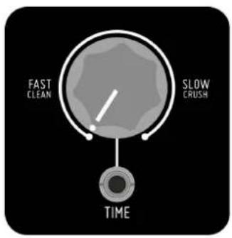
text_image
FAST CLEAN SLOW CRUSH TIME
text_image
+ FEEDBACKFEEDBACK
After being processed by the Delay circuit, the signal pass thru another VCA circuit and returns its way back to the Delay. This process called Feedback is the responsible of create the repetitions that essentially conforms the effect that we mean by Delay.
Using the Feedback pot and its dedicated CV input we can control the amount of those repetitions. As well as in Time section, the CV input sums the incoming voltage to Feedback pot position. +/-10V expected.
DRY/WET
This circuit controls the balance between the original and the processed signal present at the main output (OUT). The dedicated CV input sums the incoming voltage to the current position of the Dry/Wet pot. +/-10V expected.

text_image
DRY/WET +FUNCTIONAL BLOCKS
CRUSH SECTION
The Crush section is the most unique feature of Crush Delay. It is formed by three Crush modifiers designed with circuit bending techniques. Those modifiers affects the Delay circuit changing its behaviour and allowing you to create different tonalities and noise sounds.
Each modifier can be activated manually via its dedicated switch or by feeding a Gate signal on its Gate Input. Gate Input threshold: 3V.
Combining the modifiers you will have a access to a vast palette of noises and textures that can be used in many different ways. From ambient/drone patches to even percussion sounds.
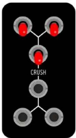
chemical
Diagram of a mechanical or chemical process with three red components connected to a central 'CRUSH' nodeMISCELANEA | SPECS & CREDITS
* Size: 11HP
* Depth: 30mm
* +12v: 130mA
* -12v: 30mA
* Design: Pascual Rocher
* Special thanks to all Befaco Team for their unvaluable help during the development process.